Lumination TM LED Luminaire (IS Series)
|
|
|
- Ralf Peters
- 5 years ago
- Views:
Transcription


1 GE Lighting Installation Guide Lumination TM LED Luminaire (IS Series) There are three types of fixtures: Starter (ISSseries) Continuous (ISCseries) Independent (IS1series) Use Starter Kit in general case. Use Starter SKU if preferred. BEFORE YOU BEGIN Read these instructions completely and carefully. Important notes included below and on page 3. RISK OF ELECTRICSHOCK Turn power off before inspection, installation or removal. Properly ground electricalenclosure. RISK OF ELECTRICSHOCK Follow all NEC and local codes. Use only UL approved wire for input/output connections. Minimum size 18 AWGor 14 AWGfor continuous runs. When using multi-branch wire circuits with a shared neutral, do not operate any circuit with the neutral open. Also ensure all neutral connections are secure before energizing the circuit. An open neutral can cause an overvoltage condition at the luminaire power supply. Save These Instructions Use only in the manner intended by the manufacturer. If you have any questions, contact themanufacturer. Prepare Electrical Wiring Electrical Requirements The LED fixture must be supplied with VAC, 50/60Hz or 347V, 50/60Hz and protected by a max. 20 ampere circuit breaker. Use min. 75 C supply conductor. 347V power should only be supplied to luminaires with voltage code D. Grounding Instructions The grounding and bonding of the overall system shall be done in accordance with National Electric Code (NEC) Article 600 and local codes. imagination at work WARNING/AVERTISSEMENT RISQUES DE DÉCHARGESÉLECTRIQUES Coupez l alimentation avant d inspecter, installer ou déplacer le luminaire. Assurez-vous de correctement mettre à la terre le boîtier d alimentation électrique. RISQUESD INCENDIE Respectez tous les codes NEC et codes locaux. N utilisez que des fils approuvés par UL pour les entrées/sorties de connexion. Taille minimum 18 AWGou 14 AWGpour les rangées continues. Lorsque vous utilisez des circuits câblés à branches multiples avec un neutre commun, ne mettez aucun circuit en service avec le neutre ouvert. Assurez-vous également que tous les raccords neutres soit sécurisés avant de mettre le circuit sous tension. Un neutre ouvert peut causer une condition de surtension à l alimentation du luminaire. Components Supplied: Luminaire 2 MountingBrackets End Caps (2 supplied with IS1 series and ISS series) Note: In general case, with the Starter Kit, the Starter SKU will not be required. Tools and Components Required: T15 torx or phillips #2screwdriver UL Listed conduit connections per NEC/CEC for nominal conduit trade sizes ½ or ¾ UL Listed wire connectors Table of Contents Page AccessoryKits 2 Installation of an Independent Unit (IS1) 3 Installation of a Continuous Row using a Starter Kit 4 Installation of a Continuous Row with Optional BranchCircuit 6 PSU Replacement 10 Light Engine Replacement 11 1
 93022791 - Starter Kit")

 Use if")


 Use to provide mounting")
 Use to suspend luminaire up to 10")
 Use to cover exposed")
2 Accessory Kits (purchasedseparately) Starter Kits Starter Kit (1row) Starter Kit (10rows) Use to connect a continuous row of fixtures to supply leads Mounting Brackets Standard Kit (10brackets) Use if extra brackets arerequired Anti-snaking Kit (10brackets) Use if installation geometry requires a mounting point up to 1 off axis of continuous row Joint Spanning Kit (5 brackets) Use if installation geometry requires a mounting point directly over fixture/fixture junction Suspension Kits Upper Mounting Kit (pack of2) Use to provide mounting anchor in finished ceiling Lower Mounting Kit (pack of 2) Use to suspend luminaire up to 10 below fixed structure or Upper MountingKit Power Feed CanopyKit (pack of 1) Use to cover exposed junction box in pendant mount applications 2


![shall not exceed 15A for lumen codes [42], [52], [84], or [A0]. Maxiumum driver current through connected fixtures shall not exceed 12A for lumen codes [65], [85], [A3], [A7], [A1], [A2], [B1] or[b4].](/docs-images/96/127325556/images/3-2.jpg "IS series luminaires come in two versions: continuous units (ISC series) and independent units (IS1 series).")


3 IMPORTANT - Maximum Length of Electrical Run IS of First Generation Lumen Code Voltage A E,G,S or J B,F or K M,N,P or R U,V,W or X 120V V or 347V Please see technical data sheet for electrical properties to ensure safe installation. Under any circumstance, maximum driver current through connected fixtures shall not exceed 15A for types A, G, J, B, F, K, or E. Maximum drive current through connected fixtures shall not exceed 12A for types M, N, P, R. IS of Second Generation LumenCode [65] [85] [A1][A2] [42] [84] [52][A0] Voltage [A3][A7] [B1][B4] 120V V or347v Maximum driver current through connected fixtures shall not exceed 15A for lumen codes [42], [52], [84], or [A0]. Maxiumum driver current through connected fixtures shall not exceed 12A for lumen codes [65], [85], [A3], [A7], [A1], [A2], [B1] or[b4]. IS series luminaires come in two versions: continuous units (ISC series) and independent units (IS1 series). A continuous electrical run will consist of a number of continuous units up to a maximum current specified above. When installing luminaires use clean gloves in order to avoid fouling the reflective surface. To insure a clean fixture, install the fixture with the plastic bag around the fixture, and then remove plastic bag upon completion of any and all construction related activity. If two additional circuits are included in luminaire, they must be connected in daisy chain to the same circuit breaker as per diagram below and total current not exceeding a maximum of 15A or 12A (per above comment). Circuit #1 Breaker Circuit #2 Daintree Node Identiftcation Label Installation of an Independent Unit (IS1) Choose suspensionmethod Daintree Node identification label installed on luminaire back reflector. Remove package with smaller label. This label is to be used for customer floor plan or records. 1 2 Carefully unpack unit and inspect for defects before installing. Wear work gloves to prevent dirt and oil from being transferred to the luminaire. NOTE: When installing luminaires use clean gloves in order to avoid fouling the reflective surface. Attach mounting bracket to ceiling support structure either directly or using a GE suspension kit according to the suspension kit instructions (see page 2). Maximum distance between suspension points shall not exceedthelengthof theluminaire. 3


.")

 Dimming wires 6")
 wires of theacline to thesimilarly colored")


 to the")


+ (0-10V) Black White Green")

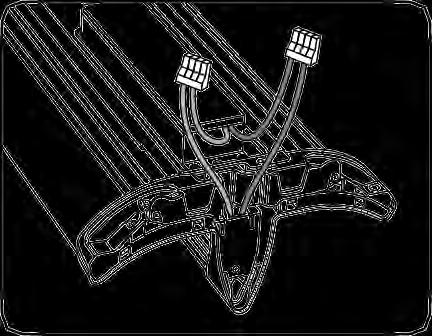
4 ACline 3 Prepare luminaire for installation by loosening the PSU cover screws and removing the cover. 4 For 347V ftxture: Loosen PSU cover 5 Carefully remove appropriate knockout screws and remove two covers. for AC line input wires (inner knockout for ½ conduit, outer knockout for ¾ conduit). Install listed electrical fittings in the knockout holes for wire protection and pass supply conduit through electrical fittings. ACline PSU wires Dimming line (optional) Dimming wires 6 Connect the green (ground), black (line) and white (neutral) wires of theacline to thesimilarly colored wires of the power supply unit using separate UL listed wire nuts. 7 Optional dimmer: Install UL listed electrical fitting and insert dimming control wires through. Connect dimming control wires (grey and violet for 0-10V or violet and violet/white strip for DALI) to the similarly colored fixture wire using separate UL listed wire nuts. 8 Clip luminaire to the previously installed mountingbrackets. Wiring Diagrams DALI Fixture Line Black Neutral White Ground Green DALI Violet/White DALI Violet 0-10V Fixture Line Neutral Ground (0-10V)+ (0-10V) Black White Green Violet Grey 9 Fix the mounting position and secure the suspension by tightening the two screwson both mountingbrackets. 10 Replace power supply cover(s) by sliding over the captive screws and secure by tightening them. Note: When installation iscomplete, all lead wires and connectors shall be totallyenclosed. 4

 Next fixture in the row Direction of continuous row")


+ (0-10V) Black White Green Violet Grey Previously hung unit Newunit 3 4 Toadd a continuous unit to")
5 Installation of a Continuous Row using a Starter Kit Use starter kits as a convenient way to install continuous rows. Starter kits are ordered separately (SKU provides parts for 1 continuous row, SKU provides parts for 10 continuous rows). CAUTION THERE IS A REqUIRED DIRECTION FOR ASSEMBLING A CONTINUOUS ROW. Ceiling First fixturein the row ACline Dimming line (optional) Next fixture in the row Direction of continuous row installation Continuous runs must begin with a first unit that is suspended at both ends. Use provided end-caps from starter kits to begin and terminate the row. For mechanical installation, follow steps 1-6 described earlier in these installinstructions. Connect to power harness in driverenclosure Connect to dimmingharness in driverenclosure Connect to AC line using separateul listed wire nuts Connect to next fixture in continuous row Connect to dimmingline (optional) using separate UL listed wirenuts Connect to next fixture in continuous row 1 Use provided starter power harness as an extension 2 A dimming starter harness is provided to optionally for the first fixture in the row. connect the dimming through wiring to the dimming line. Wiring Diagrams DALI Fixture Line Black Neutral White Ground Green DALI Violet/White DALI Violet 0-10V Fixture Line Neutral Ground (0-10V)+ (0-10V) Black White Green Violet Grey Previously hung unit Newunit 3 4 Toadd a continuous unit to a continuous 5 Remove the PSU cover from the run, first suspend the new unit as it is done previously hung luminaire if present. in steps 9 and 10 for the independent unit. Position the non-power-supply end of the luminaire near the power-supply end of the previously hung luminaire. 5


")

6 Pull out continuous wiring Align tabs withslots Pushdown to engage 6 Pull the continuous wiring out of the luminaire being mounted and slide the bridge of the luminaire down onto the bridge of the already installed luminaire so that the tabs and slots at top and bottom nest into one another. The bridges will engage with a loud click when fully mated. 7 Connect the power and control connectors of the through wiring harness. 8 At the beginning of the row, push the wiring inside the cavity of the bridge. 9 Clip one end-cap at the beginning of the row and one at the end (provided in the starter kits). 10 Replace the PSU cover(s) and secure using the mounting screws. Note: When installation is complete, all lead wires and connectors shall be totally enclosed. 6


.")

7 Installation of a Continuous Row with Optional Branch Circuit CAUTION THERE IS A REqUIRED DIRECTION FOR ASSEMBLING A CONTINUOUS ROW. Ceiling First fixturein the row ACline Dimming line (optional) Next fixture in the row Direction of continuous row installation For mechanical installation, follow steps 1-6 described earlier in these installinstructions. AC from 1st circuit Starter harness 1 Carefully remove appropriate knockout for AC line input wires (inner knockout for ½ conduit, outer knockout for ¾ conduit). Install listed electrical fittings in the knockout holes for wire protection and pass supply conduit through electrical fittings. 2 1st circuit connection: Connect the green (ground), black (line) and white (neutral) wires of the AC line to the similarly colored wires of the starter harness using the provided push-in wire nuts (starter unit) or connect using wire nuts if using a starter kit (see above). 7


 or using wire nuts (starter")

 will be connected to the second")


 from first fixture to")
8 Dimming line (optional) Dimming connections First circuitwires Second circuitwires Brown, Brown/white stripewires 3 Optional dimmer: Install UL listed electrical fitting and insert dimming control wires through. Connect dimming control wires (grey and violet for 0-10V or violet and violet/white stripe for DALI) to the similarly colored fixture wires using the provided push-in wire nuts (starter unit) or using wire nuts (starter kit). 4 2nd circuit connection: Install listed electrical fittings in the second knockout holes for wire protection and pass supply conduit through electrical fittings. The second circuit wires (line and neutral) will be connected to the second luminaire in the continuous run. Leave them unconnected to the brown and brown/white stripe wires fornow. Purple, grey Brown, brown-white Green, black,white Align tabs withslots Pushdown to engage Pull out continuous wiring 5 Pull the continuous wiring out of the next luminaire being mounted and slide the bridge of the luminaire down onto the bridge of the already installed luminaire so that the tabs and slots at top and bottom nest into one another. The bridges will engage with a load click when fully mated. Wiring Diagrams Brown Brown/white stripe DALI 0-10V Fixture Fixture Circuit Line Black Circuit Line #1 Neutral White #1 Neutral Black White Circuit #2 Line Neutral Brown Brown/white Circuit #2 Line Neutral Brown Brown/white Ground Green Ground Green DALI Violet/White 0-10V Violet 6 Connect the power and control connectors of the through wiring harness. Connect AC Circuit #1 (black, white and green harness) from first fixture to AC Circuit #1 from second fixture. Connect AC Circuit # 2 (brown and brown/white stripe harness) from first fixture to AC Circuit #2 from second fixture and connect second circuit supply lines of starter unit. DALI Violet 0-10V Grey(18AWG) 8


 and")

 AC wire using the push-in wire nut.")
 ACwire using thepush-inwire nut.")

 and secure using the mounting")
9 Connecting a Unit to AC Circuit #1 or AC Circuit #2 AC Circuit #2 AC Circuit #1 Black and white wires Dimming PSU 7 Locate the black (line) and white (neutral) wires on the PSU. Pull the wires out of the box to have good access. AC Circuit #1 Connections AC Circuit #2 Connections AC Circuit #2 AC Circuit #1 8A Connect the black (line) and the white (neutral) wires of the PSU to the AC lines similarly colored wires using the push-inwire nuts. 8B Connect the black (line) of the PSU with the brown (line) AC wire using the push-in wire nut. Connect the white (neutral) wire of the PSU with the brown/white (neutral) ACwire using thepush-inwire nut. 9 To terminate a mechanical run take the end cap from the starter luminaire or starter kit and clip down onto the last bridge. 10 Replace the PSU cover(s) and secure using the mounting screws. Note: When installation is complete, all wiring and connectors shall be totally enclosed. 9
 Wire cutter T15 Torx or Phillips #2screwdriver")


.")
 and")

10 PSU Replacement Procedure Tools and Parts Required: New power supply unit (PSU) Wire cutter T15 Torx or Phillips #2screwdriver UL approvedwire connectors (4-pin) 1 Disconnect the luminaire power source. Mounting bracket not shown for clarity AC Dimming DC 2 Loosen 3 screws and remove the PSU cover. 3 Locate the DC (red and blue), AC (green, white and black) and Dimming connections (purple and gray). Do not cut greenac wires Remove oldpsu Other wires hiddenfor clarity 4 Cut the original DC, AC (do not cut the green wire) and Dimmingconnections. 5 Unscrew the old PSU and remove. Install new PSU AC Dimming DC Other wires hiddenfor clarity 6 Install the new PSU using a star washer under each screw. 7 Reconnect the DC, AC, and Dimming wires using UL approved connectors. Reattach the PSU cover. 10


 Heatsink AC wires")


11 Light Engine Replacement Procedure For optical codes A, B, E, F, G, J, K, M, N, P, R, S 1 Disconnect the luminaire power source. Ceiling Move suspension point to avoid cantilever effect. 2. Remove 2 screws on PSU cover. Disconnect wires to adjacent fixtures. 3. Unsnapboth ends. 3 Fixture toreplace 2 Remove fixture from ceiling. DC wires (blue/red) Dimming wires (grey/purple) Heatsink AC wires (black/white/green) 3 Unscrew and remove the PSU cover. 4 Locate AC, DC and dimming wires coming from heatsink and cut or disconnect them (other wires not shown for clarity). Groundwire 5 Remove ground screw and wire. 6 Pull out the thru wiring from the opposite end. Save wiring forlater. 11


 through the new light engine and")
 Bottomhole")


 Light engine 11")
12 Upper bridge Blue/red wiring Lower bridge Light engine New light engine Wires exitbottom hole of bridge 7 Remove 4 screws to detach upper bridge from lower bridge and replaceable light engine. 8 Pull thru wiring (saved from Step 6) through the new light engine and lower bridge. Top hole (blue/red wires) Bottomhole (thruwiring) 9 At PSU side, insert light engine into bottom bridge. Blue/red wiring passes through the top hole. Thru wiring passes through the bottom hole. 10 Reattach the ground wire and screw. Upper bridge Lower bridge DCwires (blue/red) Light engine 11 Reassemble the upper and lower bridge to the fixture with 4 screws. 12 Reconnect DC wires according to color (other wires not shown for clarity). 12
")
 13")

.")


![[42][52][84][A0] Only](/docs-images/96/127325556/images/13-10.jpg "1 With a flathead")


13 AC wires (black/white/green) Dimming wires (grey/purple) 13 Reconnect thru wires according to color (other wires not shown for clarity). 14 Push wires into tray and reattach cover. 15 Make sure no wires are pinched. NOTE: Make sure all wires and connectors and are properly enclosed. How To Replace Light Engine in the Field For LumenCode [42][52][84][A0] Only 1 With a flathead screwdriver, open accessdoor. 2 Disconnect DCpower. 3 With a flathead screwdriver, unsnap clip near the end. Continue unsnapping remaining clips. 4 Remove heatsink. Reverse steps to install the new light engine. 13


14 How To Replace Light Engine in the Field For LumenCode [65][85][A3][A7][A1][A2][B1][B4] Only 1 TURN OFF POWER. Remove PSU cover. 2 Cut blue and red wires from light engine (other wires hidden for clarity). 3 With a flathead screwdriver, open access door. New light engine 4 With a flathead screwdriver, unsnap clip near the end. Continue unsnapping remaining clips. 5 Remove removeable light engine. 6 Take the red and blue wires of the new light engine and fish them through opening. 7 Clip removeable light engine into place. 8 Close the access door. 9 Reconnect blue and red wires from the new light engine (other wires hidden for clarity). Reinstall PSU cover. 14
Lumination TM LED Luminaires Suspended LED Fixture (Series EP14)
") GE Lighting Solutions Installation Guide Lumination TM LED Luminaires Suspended LED Fixture (Series EP14) Features Long life (50,000 hour rated life) 5 year warranty IP30 Dry location rated BEFORE YOU
GE Lighting Solutions Installation Guide Lumination TM LED Luminaires Suspended LED Fixture (Series EP14) Features Long life (50,000 hour rated life) 5 year warranty IP30 Dry location rated BEFORE YOU
Albeo TM LED Luminaire Heavy Industrial High Bay Lighting (ABR1-Series)
") GE Lighting Installation Guide Albeo TM LED Luminaire Heavy Industrial High Bay Lighting (ABR1-Series) Features UL 1598 Suitable for Wet Locations IP66 Rated Ingress Protection BEFORE YOU BEGIN Read these
GE Lighting Installation Guide Albeo TM LED Luminaire Heavy Industrial High Bay Lighting (ABR1-Series) Features UL 1598 Suitable for Wet Locations IP66 Rated Ingress Protection BEFORE YOU BEGIN Read these
Lumination TM LED Luminaires LAL Series - Continuous Run Option
 GE Lighting Installation Guide Lumination TM LED Luminaires LAL Series - Continuous Run Option BEFORE YOU BEGIN Read these instructions completely and carefully. WARNING/AVERTISSEMENT RISK OF ELECTRIC
Lumination TM LED Luminaire RC/LRC/RX/LRX Series - New Construction Frame
 Installation Guide Lumination TM LED Luminaire RC/LRC/RX/LRX Series - New Construction Frame BEFORE YOU BEGIN Read these instructions completely and carefully. RISK OF ELECTRIC SHOCK Turn power off before
INSTALLATION INSTRUCTIONS LIGHTPLANE 3.5. LP3.5 Suspended LED. A nd Avenue, Unit 1. CA P E W alwusa.
 Oakland, INSTALLATION INSTRUCTIONS LIGHTPLANE 3.5 LP3.5 Suspended LED A 1035 22nd Avenue, Unit 1 n CA 94606 P 510.489.2530 E TalkToUs@alwusa.com W alwusa.com Safety & Warnings! 1. Read all instructions.
INSTALLATION INSTRUCTIONS SUPERPLANE 2.5. Suspended. A nd Avenue, Unit 1 Oakland, CA P E W alwusa.
 INSTALLATION INSTRUCTIONS SUPERPLANE 2.5 Suspended A 1035 22nd Avenue, Unit 1 Oakland, CA 94606 P 510.489.2530 E TalkToUs@alwusa.com W alwusa.com SP2.5S - Safety & Warnings! 1. Read all instructions. 2.
Tetra minimax. LED Lighting System. BEFORE YOU BEGIN Read these instructions completely and carefully. Installation Guide
 Installation Guide Volt Tetra minimax LED Lighting System GEMMRD-W, GEMMGL-W, GEMMBL-W BEFORE YOU BEGIN Read these instructions completely and carefully. WARNING/AVERTISSMENT RISK OF ELECTRIC SHOCK Turn
INSTALLATION INSTRUCTIONS MOONRING 1 LP1/MR1
 INSTALLATION INSTRUCTIONS MOONRING 1 LP1/MR1 Suspended, Ceiling LED n A 1035 22nd Avenue, Unit 1 Oakland, CA 94606 P 510.489.2530 E TalkToUs@alwusa.com W alwusa.com Safety & Warnings! 1. Read all instructions.
WARNING/AVERTISSEMENT. Coupez l alimentation électrique à la boîte de fusibles ou au disjoncteur avant servicing or installing product.
 Tetra Contour LS LED Lighting System GEXNLBL-1, GEXNLGL-1, GEXNLRD-1, GEXNL65-1, GEXNL32-1 Installation Guide 24 Volt BEFORE YOU BEGIN Read these instructions completely and carefully. WARNING/AVERTISSEMENT
MOONRING 1.5 MOONRING 3
 INSTALLATION INSTRUCTIONS MOONRING 1.5 MOONRING 3 MR1.5 & MR3 Suspended, Ceiling LED n A 1035 22nd Avenue, Unit 1 Oakland, CA 94606 P 510.489.2530 E TalkToUs@alwusa.com W alwusa.com Safety & Warnings!
Lumination TM LED Luminaire LUR Series
 Installation Guide Lumination TM LED Luminaire LUR Series BEFORE YOU BEGIN Read these instructions completely and carefully. WARNING/AVERTISSEMENT RISK OF FIRE OR ELECTRIC SHOCK Turn power off before inspection,
INSTALLATION INSTRUCTIONS LED RETROFIT ASSEMBLY (LRA) Rev F
 Rev F") SAFETY S IMPORTANT SAFETY INFORMATION SUITABLE FOR DRY OR DAMP LOCATIONS. NOT FOR USE WITH PHASE CUT DIMMERS. Risk of shock. Disconnect power before installation. DANGER CONVIENT AUX EMPLACEMENTS HUMIDES.
SAFETY S IMPORTANT SAFETY INFORMATION SUITABLE FOR DRY OR DAMP LOCATIONS. NOT FOR USE WITH PHASE CUT DIMMERS. Risk of shock. Disconnect power before installation. DANGER CONVIENT AUX EMPLACEMENTS HUMIDES.
READ AND FOLLOW ALL SAFETY INSTRUCTIONS 1. DANGER RISK OF SHOCK DISCONNECT POWER BEFORE INSTALLATION
 UR Series LED Upgrade Kit Includes: 24" Linear Option IMPORTANT SAFEGUARDS When using electrical equipment, basic safety precautions should always be followed including the following: READ AND FOLLOW ALL
IMPORTANT SAFEGUARDS When using electrical equipment, basic safety precautions should always be followed including the following:
 ZR-RK Series LED Retrofit Troffer Kit Includes: ZR22RK and ZR24RK Standard and Emergency Luminaires IMPORTANT SAFEGUARDS When using electrical equipment, basic safety precautions should always be followed
Spun Bay Installation Standard Version (non dimmable), Hook Mount
, Hook Mount") Spun Bay Installation Standard Version (non dimmable), Hook Mount WARNING: Make sure that all power is turned off while installing fixture. Do not turn power on until fixture is completely installed. Turn
Spun Bay Installation Standard Version (non dimmable), Hook Mount WARNING: Make sure that all power is turned off while installing fixture. Do not turn power on until fixture is completely installed. Turn
HBDBM High Bay Series
 HBDBM High Bay Series INSTALLATION INSTRUCTIONS The High Bay Luminaire is ideal for installations with mounting heights over 25 feet. The fixture can be mounted with a hook or pendant with flexible adjustments
Horticulture Batten LED Luminaire
 GE Lighting Installation Guide Horticulture Batten LED Luminaire LED Lighting System BEFORE YOU BEGIN Read these instructions completely and carefully. WARNING/AVERTISSEMENT RISK OF ELECTRIC SHOCK Turn
Wet Rated Batten LED Luminaire
 Installation Guide Wet Rated Batten LED Luminaire LED Lighting System BEFORE YOU BEGIN Read these instructions completely and carefully. WARNING / AVERTISSEMENT RISK OF ELECTRIC SHOCK Turn power off before
High Bay Luminaire Series
 High Bay Luminaire Series INSTALLATION INSTRUCTIONS The High Bay Luminaire is ideal for installations with mounting heights over 25 feet. The fixture can be mounted with a hook or pendant with flexible
SURFACE/CEILING & SUSPENDED MOUNT INSTALLATION
 SURFE/CEILING & SUSPENDED MOUNT INSTALLATION E477827 E477827 APPLICATION NL luminaires are designed for use indoors, outdoors, wet locations, areas containing moisture, dirt, corrosion, vibration and rough
INSTALLATION INSTRUCTION Aether 2 Shallow Recessed Housing
 SAFETY INSTRUCTIONS IMPORTANT: NEVER attempt any work without shutting off the electricity. Read all instructions before installing. System is intended for installation by a qualified electrician in accordance
INSTALLATION INSTRUCTION Aether 3.5 Color Tunable LED Downlight
 SAFETY INSTRUCTION IMPORTANT: NEVER attempt any work without shutting off the electricity. Read all instructions before installing. System is intended for installation by a qualified electrician in accordance
INSTALLATION INSTRUCTIONS
 INDIGO-CLEAN TECHNOLOGY RETROFIT KIT INSTALLATION INSTRUCTIONS 1 IMPORTANT SAFETY INFORMATION Risk of shock. Disconnect power before installation. DANGER- RISQUE DE CHOC- COUPER L ALIMENTATION AVANT L
INSTALLATION INSTRUCTION Oculux 3.5" Architectural Downlight R3CRN-11, R3CSN-11
 . INSTALLATION INSTRUCTION SAFETY INSTRUCTION IMPORTANT: NEVER attempt any work without shutting off the electricity. Read all instructions before installing. System is intended for installation by a qualified
Installation Instructions 4 Gravity Enhanced Color Adjustable
 Installation Instructions 1 of 5 Risk of electrical shock. Disconnect power before servicing or installing luminaire. Risk of injury or damage. will fail if not installed properly. Follow installation
LS1 SERIES IMPORTANT: READ ALL INSTRUCTIONS THOROUGHLY AND CAREFULLY PRIOR TO INSTALLATION OF LINEAR SERIES FIXTURES AND RETAIN FOR FUTURE REFERENCE.
 The LS1 Series of commercial and industrial LED fixtures is designed to be used in utility strip applications using suspension or surface mount installation. The LS1 Series is designed for use in 120 277V,
Power Break II Circuit Breaker Accessories Motor Operator Mechanism
 g GEH 6281E Power Break II Circuit Breaker Accessories Motor Operator Mechanism Introduction The Motor Operator Mechanism, shown in Figure 1, can be installed in 800 4000 A frame Power Break II circuit
LAL SERIES LED LUMINAIRE
 INSTALLATION, OPERATION & MAINTENANCE DATA SHEET LAL SERIES LED LUMINAIRE CAUTION: LAL SERIES LED LUMINAIRE Before installing, make sure you are compliant with area classifications, failure to do so may
Elle Surface Mounting Instructions
 Step 1: Preparation, page 2 Warnings CAUTION risk of fire and this product must be installed in accordance with the applicable installation code by a person familiar with the construction and operation
WARNING / AVERTISSEMENT
 TM Arize LED Lighting System Lynk & Life Installation Guide BEFORE YOU BEGIN Read these instructions completely and carefully. WARNING / AVERTISSEMENT RISK OF ELECTRIC SHOCK RISQUES DE DÉCHARGES ÉLECTRIQUES
OSQ Series IMPORTANT SAFEGUARDS READ AND FOLLOW ALL SAFETY INSTRUCTIONS SAVE THESE INSTRUCTIONS FOR FUTURE REFERENCE. LED Area Light TO INSTALL:
 OSQ Series LED Area Light Direct Pole Mount IMPORTANT SAFEGUARDS When using electrical equipment, basic safety precautions should always be followed including the following: READ AND FOLLOW ALL SAFETY
MAXLITE RKT LED Retrofit Kit
 MAXLITE RKT LED Retrofit Kit Description and Intended Use The RKT LED Retrofit Kit is a high performance LED Fixture upgrade kit designed to replace the original components inside 2 x2 and 2 x4 fluorescent
Installation Instructions MX LED Enhanced Color Adjustable
 Installation Instructions 1 of 5 MX Enhanced Color Adjustable Risk of electrical shock. Disconnect power before servicing or installing luminaire. Risk of injury or damage. will fail if not installed properly.
ECO-T LED RECESSED TROFFER USER MANUAL
 ECO-T LED RECESSED TROFFER USER MANUAL INSTALLATION GUIDE FOR: 2X2: MLRT22D4535 MLRT22D4541 MLRT22D4550 2X4: MLRT24D5535 MLRT24D5541 MLRT24D5550 Thank you for purchasing this MaxLite product. For additional
Elle Surface Mounting Instructions
 Step 1: Preparation, page 2 Warnings CAUTION risk of fire and this product must be installed in accordance with the applicable installation code by a person familiar with the construction and operation
Installation Instruction
 T F W 604.549.9379 604.549.9555 fluxwerx.com Installation Instruction DRIVER ENCLOSURE Ceiling Type Version Grid Battery Pack GRID MOUNT INSTALL OPTIONS OPTION 1: Standard Vertical Grid drivers can be
LED Flat Panel Installation Instructions For 1 x4, 2 x2, and 2 x4 LED Flat Panels (FP Series)
") LED Flat Panel Installation Instructions For 1 x4, 2 x2, and 2 x4 LED Flat Panels (FP Series) PLEASE READ THESE INSTRUCTIONS BEFORE INSTALLATION PLEASE READ THESE INSTRUCTIONS BEFORE INSTALLATION SAFETY
LED Flat Panel Installation Instructions For 1 x4, 2 x2, and 2 x4 LED Flat Panels (FP Series) PLEASE READ THESE INSTRUCTIONS BEFORE INSTALLATION PLEASE READ THESE INSTRUCTIONS BEFORE INSTALLATION SAFETY
LED Garage Light INSTALLATION INSTRUCTIONS. *Model number noted on carton label
 LED Garage Light *Model number noted on carton label INSTALLATION INSTRUCTIONS Model Number / Número de Modelo / Numéro des modèle SGLL 24 PIR (24 LED Garage Light) Actual Dimensions 10 W x 3-1/2 H x 24-1/2
General Installation Instructions LED
 General Installation Instructions LED To reduce the risk of death, personal injury or property damage from fire, electric shock, falling parts, cuts/abrasions and other hazards, please read all warnings
LED IMPORTANT SAFETY INSTRUCTIONS
 LED IMPORTANT SAFETY INSTRUCTIONS READ AND FOLLOW ALL SAFETY INSTRUCTIONS! SAVE THESE INSTRUCTIONS AND DELIVER TO OWNER AFTER INSTALLATION To reduce the risk of death, personal injury or property damage
INSTALLATION INSTRUCTIONS LED Canopy Retrofit Kit
 INSTALLATION INSTRUCTIONS LED Canopy Retrofit Kit TRMUNV065ECxyyZ TRAUNV065ECxyyZ Installation Instructions subject to change without notice. Page 1 of 8 1.0 INSTALLATION WARNINGS 1. 2. 3. 4. 5. 6. "THIS
Cable Cubby 1202 and 1402 Installation Guide
 Cable Cubby 0 and 40 Installation Guide IMPORTANT: Go to www.extron.com for the complete user guide, installation instructions, and specifications. This guide provides instructions for an experienced technician
Retractor SM Installation Guide
 Installation Guide IMPORTANT: Go to www.extron.com for the complete user guide, installation instructions, and specifications. This guide provides basic instructions for an experienced technician to quickly
Cable Cubby 650 UT Installation Guide
 e NT: RTA.com for thtion O P IM tron talla w.ex uide, ins ations. o ww Go t te user g specific nd ple com ctions, a u instr Cable Cubby 650 UT Installation Guide This guide provides instructions for an
poollux Power plx-pw60 & plx-pw100
 poollux Power plx-pw60 & plx-pw100 ETL LISTED Conforms to UL STD 379; Certifi.ed.to.CSA.STD.C22.2.#218.1 5005508 Installation Instructions Read all instructions before attempting to perform installation
INSTALLATION INSTRUCTION
 Volta 4.5 - Downlight Round SAFETY INSTRUCTION IMPORTANT: NEVER attempt any work without shutting off the electricity. Read all instructions before installing. System is intended for installation by a
Strip Fixture URS Light Bar Retrofit Installation Instructions Revised:
 Strip Fixture URS Light Bar Retrofit Installation Instructions Revised: 20180126 These instructions do not purport to cover all details or variations in components nor to provide for every possible contingency
Installation Instructions: Eco Linear High Bay
 Installation Instructions: Eco Linear High Bay Installation Notes & Precautions: Read all precautions, warnings, instructions contained in this document. These instructions can be used to install Eco Linear
I. Pendant Mount Installation
 LED HIGH BAY MAX Luminaires for High Bay Applications HBM SERIES IMPORTANT SAFEGUARDS When using electrical equipment, basic safety precautions should always be followed, including the following: 1 THIS
INSTALLATION INSTRUCTION
 SAFETY INSTRUCTION IMPORTANT: NEVER attempt any work without shutting off the electricity. Read all instructions before installing. System is intended for installation by a qualified electrician in accordance
Fan Relay Board (FRBii) Assembly
 Assembly") Fan Relay Board (FRBii) Assembly Installation, Operation, and Maintenance Instructions PK-FCU030-0, PK-FCU050-0 Part No. 24-10143-1221, Rev. A Issued February 2017 Application Refer to the QuickLIT website
Fan Relay Board (FRBii) Assembly Installation, Operation, and Maintenance Instructions PK-FCU030-0, PK-FCU050-0 Part No. 24-10143-1221, Rev. A Issued February 2017 Application Refer to the QuickLIT website
Specification Grade Contemporary Wall Mount/Technical Installation Data
 AVAILABLE CONFIGURATIONS RECESSED MOUNT SURFACE MOUNT MOUNTING REQUIREMENTS A. Recessed Mount: Minimum 4-Gang Box, 1-5/8 in. Deep (72.8 Cubic Inches) with 4-Gang Box Cover (20.3 Cubic Inches) B. Surface
HP-2 / HP-6 Direct Installation Instructions Overview
 Overview Helpful Video 0-10V Dimming Step 1 Mounting & Suspension Page 2 Step 2 Identification & Preparation Page 3 Step 3 Mounting to Structure Page 4 NOTE Step 4 Page 5 This installation requires proper
Installation Instructions
 Installation Instructions FHEZ10A24 FHEZ17A48 Page 1 of 7 IMPORTANT SAFEGUARDS READ AND FOLLOW ALL SAFETY INSTRUCTIONS. 1. Do not mount near gas or electric heaters. 2. Do not attempt to service the battery.
E E VDC COOLEDGE TILE INTERIOR INSTALLATION INSTRUCTIONS. Caution: Observe precautions for handling electrostatic sensitive devices.
 5 YEAR WARRANTY 5 YEAR WARRANTY COOLEDGE TILE INTERIOR INSTALLATION INSTRUCTIONS E354088 LISTED AC E354088 58VDC E354088 E354088 5 5 YEAR WARRANTY 5 YEAR WARRANTY E354088 Caution: Observe precautions for
Installation Instructions Sero / Qub Pendant RETROFIT CONSTRUCTION- INACCESSIBLE CEILING Mounting Option GP
 WARNINGS: Do not assemble continuous run on the ground and lift into place. Joints will distort and not create a tight fit. Joining hardware will have to be purchased and replaced. Risk of electrical shock
Installation Instructions
 at :: rangehoods. com Call 1-800-667-8721 anywhere in the US and Canada - www.rangehoods.com Installation Instructions ZV950 36" Stainless Steel Vent Hood Monogram. We bring good things to life. GE Monogram
LUNERA VERTICAL E26 LED FLOODLIGHT LED Replacement for E26 Medium Base Floodlights Type B Ballast Bypassed
 Installation Guide LUNERA VERTICAL E26 LED FLOODLIGHT LED Replacement for E26 Medium Base Floodlights Type B Ballast Bypassed Installation Description The LUNERA VERTICAL E26 LED FLOODLIGHT is a line driven
TOYOTA COROLLA ILLUMINATED DOOR SILLS Preparation
 Preparation Part Number: PT942-02140 Kit Contents Item # Quantity Reqd. Description 1 1 Illuminated Scuff plate, Front Right Hand 2 1 Illuminated Scuff plate, Front Left Hand 3 1 Door Scuff plate, Rear
CONTENTS. This Product is Certified by CANADIAN STANDARDS ASSOCIATION and Bears the Mark:
 This Product is Listed by UNDERWRITERS LABORATORIES INC. and Bears the Mark: This Product is Certified by CANADIAN STANDARDS ASSOCIATION and Bears the Mark: SLATER SCD Installation Instructions For Self-Contained
INSTALLATION INSTRUCTION Bollard Light 12V
 Bollard Light 12V 6611/6621/6631/6641/6651 SAFETY INSTRUCTION IMPORTANT: NEVER attempt any work without shutting off the electricity. Read all instructions before installing. System is intended for installation
Installation Instructions: Eco SpunBay LED High Bays
 Installation Instructions: Eco SpunBay LED High Bays Installation Notes & Precautions: Read all precautions, warnings, instructions contained in this document. These instructions can be used to install
Installation Instructions If you have questions, call 800-GE-CARES or visit our website at:
 Installation Instructions If you have questions, call 800-GE-CARES or visit our website at: www.monogram.com 30", 36" and 48" Professional Vent Hoods Models: ZV48T, ZV48S ZV36T, ZV36S ZV30T, ZV30S Monogram.
Captivate Illuminated Mirror Light
 ENGLISH WARNINGS & SAFETY INFORMATION: PLEASE READ CAREFULLY FRANÇAIS MISES EN GARDE ET SÉCURITÉ: SE IL VOUS PLAÎT LIRE ATTENTIVEMENT WARNING: RISK OF FIRE OR ELECTRIC SHOCK. LUMINAIRE WIRING AND ELECTRICAL
GOMINIGO Third Brake Light Pulsar Kit. Installation Instructions
 Page 1 of 8 Mini Cooper Installation Instructions This kit allows the owner of any MINI Cooper or Cooper S to create a blinking effect from the third brake light assembly. The MINI Cooper being hit from
CFP-LED Contractor Select Flat Panel. Installation Instructions
 IMPORTANT SAFETY INSTRUCTIONS To reduce the risk of death, personal injury or property damage from fire, electric shock, falling parts, cuts/abrasions, and other hazards please read all warnings and instructions
LED IMPORTANT SAFETY INSTRUCTIONS
 READ AND FOLLOW ALL SAFETY INSTRUCTIONS! SAVE THESE INSTRUCTIONS AND DELIVER TO OWNER AFTER INSTALLATION To reduce the risk of death, personal injury or property damage from fire, electric shock, falling
1718 W. Fullerton Ave Chicago, IL Tel: Fax:
 206 Edge Lighting. All Rights Reserved. Installation Instructions for Nova Power Suspension Up/Down - Center Feed Glide Up/Down - Center Feed IMPORTANT INFORMATION - This product is suitable for indoor
Installation Instructions
 Installation Instructions If you have questions, call 800.GE.CARES or visit our website at: www.monogram.com ZV950 36" Stainless Steel Vent Hood Safety Information BEFORE YOU BEGIN Read these instructions
ELV1abbccd-e. Color Temperature: 30 = 3000K White 35 = 3500K White 40 = 4000K White 45 = 4500K White 50 = 5000K White
 GE Lighting Immersion TM Elite LED Refrigerated Display Lighting End Mullion Lights for Vertical Cases Installation Guide ELV1abbccd-e Prefix: EL = Elite V = Vertical FD = French Door 1 = Generation Light
Prismpack V, Prismalume V, Large Prismpack, Large Prismalume
 AFTER INSTALLATION DELIVER THIS MANUAL TO OWNER Holophane Company Inc. Field Service Department IMPORTANT SAFETY INSTRUCTIONS -READ THESE INSTRUCTIONS CAREFULLY BEFORE ATTEMPTING TO INSTALL OR MAINTAIN
ULTRA PERFORMANCE LED TUBE INSTALLATION INSTRUCTIONS
 Ultra Performance LED Tube Installation Instructions Page 1 of 7 ULTRA PERFORMANCE LED TUBE INSTALLATION INSTRUCTIONS These instructions do not purport to cover all details or variations in components
Luminaire Support Location Cable Mounting Kit. Non-Power Feed
 INSTALLATION INSTRUCTIONS These installation instructions are used for installing the following luminaires and kits: Luminaire Support Location Cable Mounting Kit OLE4 (suspended) Normal Power Feed Non-Power
* * APPLICABLE MODELS: 2014 > Mazda 3
 PART NUMBER: 0000 8C L48 (DIO) / 0000 89 L84 (PIO) GENUINE ACCESSORIES INSTALLATION INSTRUCTIONS Rev. AAA *550-0700-000* APPLICABLE MODELS: 2014 > Mazda 3 REQUIRED COMPONENTS: ITEM QTY DESCRIPTION Usage
GENUINE ACCESSORIES INSTALLATION INSTRUCTIONS. ITEM QTY DESCRIPTION Usage Chart Service Part Number. 1 1 Mirror Assembly w/ Compass 1
 AUTO PART NUMBER: 0000 8C P4 (DIO)/ 0000 89 P25 (PIO) REQUIRED COMPONENTS: INSTALLATION KIT: 2 SA Harness - 2 Conductor 3 0 Wire Ties 4 Wire Cover 5 A-Pillar Tether Clip (D09W-6862) 6 3 Foam Tape 7 3 Electro-Tap(wire
Lumination LED Luminaires
 Lumination LED Luminaires LUS Series with Replaceable Light Engine Project name Date Type Product Description: GE s Lumination LED fixtures with reveal TriGain technology - LUS Series Suspended fixtures
R. STAHL Schaltgeräte GmbH Geschäftsbereich Leuchten Nordstraße Weimar, Germany
 , INC. ECOLUX 6600 Series 6600/5 Explosion Protected Fluorescent Light Fixtures for Hazardous and Corrosive Applications Please read this entire document before beginning any work. 1. Safety Instructions
INSTALLATION INSTRUCTION W Track Recessed 120V Flangeless
 W Track Recessed 120V Flangeless WT4-RTL, WT8-RTL, WT12-RTL SAFETY INSTRUCTION Read all of these instructions before installing the track system. Turn off power at main switch before installing or modifying
MODELS 2 & 4 Top Conduit Linears
 INSTALLATION AND MAINTENANCE MANUAL SAFESITE AND DUROSITE LED LINEAR FIXTURE Document No: 9100-127-1885-99 Rev E December, 2016 MODELS 2 & 4 Top Conduit Linears These instructions contain important safety
HIGHBAY RAIL 400W INSTALLATION INSTRUCTIONS
 TM INSTALLATION INSTRUCTIONS IMPORTANT READ CAREFULLY BEFORE INSTALLING FIXTURE. RETAIN THESE INSTRUCTIONS FOR FUTURE REFERENCE. Fixtures must be wired in accordance with the National Electrical Code and
TM-11x1 Series Room Temperature Module
 24-10225- 4, Rev. C TM-11x1 Series Installation Instructions Part No. 24-10225-4, Rev. C Issued March 16 Applications The TM-11x1 Series of s are designed for use with the TC-9102 Direct Digital Control
System 350 S350C Temperature Slave Stage Module
 FANs 930, 930.5, 125, 121 Product/Technical Bulletin Issue Date April 8, 2014 System 350 Temperature Slave Stage Module The Temperature Slave Stage Module is used in conjunction with the A350 Temperature
EMERY SKY SUSPENDED LED LUMINAIRE
 EMERY SKY SUSPENDED LED LUMINAIRE IP20 DRY LOCATION 120V- 277V AC SAFETY & WARNINGS 1. READ AND FOLLOW ALL SAFETY INSTRUCTIONS 2. Install in accordance with national and local electrical code regulations.
Asymmetrical Installation Instructions. Components: i2cove Asymmetrical LED Light Fixtures. 12 [305mm] [918mm] 48.
![Asymmetrical Installation Instructions. Components: i2cove Asymmetrical LED Light Fixtures. 12 [305mm] [918mm] 48.](/thumbs/77/74625192.jpg "Asymmetrical Installation Instructions. Components: i2cove Asymmetrical LED Light Fixtures. 12 [305mm] [918mm] 48.") support@i2systems.com www.i2systems.com Electrical Specifications PARAMETER Input Power VALUE 8 Watts* / Ft Input Voltage 120-277V AC, 50/60 Hz Max. Fixture Run Length LED Color (CCT) 8 Watts: 120VAC:
support@i2systems.com www.i2systems.com Electrical Specifications PARAMETER Input Power VALUE 8 Watts* / Ft Input Voltage 120-277V AC, 50/60 Hz Max. Fixture Run Length LED Color (CCT) 8 Watts: 120VAC:
50 AMP TRANSFER RELAY DELAY - DUAL INPUT GENSET
 R 50 AMP TRANSFER RELAY DELAY - DUAL INPUT GENSET Transfer Relay Delay 00-00803-400 Dual Input Genset INDUSTRIAL CONTROL EQUIPMENT TYPE 1 Shore Power Rating: 120/240VAC 60HZ 1 Phase 50A/Pole Generator
Operation/Installation Instructions
 Important Information These instructions contain safety information, read and follow them carefully. Dialight will not accept any responsibility for injury, damage or loss which may occur due to incorrect
Installation Instructions
 at :: rangehoods. com Call 1-800-667-8721 anywhere in the US and Canada - www.rangehoods.com Installation Instructions 30", 36" and 48" Restaurant Style Vent Hoods Models: ZV48R ZV36R ZV30R Monogram. We
Anthony LED Lighting System Retrofit Installation Instructions For Models 101X and 101A
 Anthony LED Lighting System Retrofit Installation Instructions For Models 101X and 101A 99-16999-0000 Table of Contents 1. Removing Fluorescent Lighting... 4 1.1. Detach the lens assembly... 4 1.2. Remove
INSTRUCTION BOOK FOR. Tensioned Dual Masking Electrol
 INSTRUCTION BOOK FOR Tensioned Dual Masking Electrol Important Safety Instructions When using your video equipment, basic safety precautions should always be followed, including the following: 1. Read
INSTRUCTIONS FOR THE RELIANCE Fast/Tran TM ARL0909 & ARL0909R
 INSTRUCTIONS FOR THE RELIANCE Fast/Tran TM ARL0909 & ARL0909R THE RELIANCE Fast/Tran IS NOT FOR "DO-IT-YOURSELF" INSTALLATION. It must be installed by a qualified electrician thoroughly familiar with all
Round or Square Chicago Plenum Hi-lume Wall Wash Housing with LED Lamp for Flanged Trims E3_F_-L_WC-HL 1.0
 Installation Instructions for 90ELED-WHL-FL Round or Square Chicago Plenum Hi-lume Wall Wash Housing with LED Lamp for Flanged Trims E_F_-L_WC-HL.0 LED - ROUND/SQUARE FLANGED GENERAL PRODUCT I NFORMATION:
* * APPLICABLE MODELS: 2016 > CX-3
 PART NUMBER: 0000 8C S01(DIO) / 0000 89 S07(PIO) GENUINE ACCESSORIES INSTALLATION INSTRUCTIONS Rev. AAA *550-0688-000* APPLICABLE MODELS: 2016 > CX-3 REQUIRED COMPONENTS: ITEM QTY DESCRIPTION Usage Chart
Installation Instructions BLTR and 2BLTR Relight Assembly
 UT4540 Rev. B Installation Instructions BLTR and 2BLTR Relight Assembly This Relight assembly was engineered to upgrade most recessed fixtures mounted in T-grid ceiling installations, including most parabolic
MODELS. 2 & 4 Low Profile Linears
 INSTALLATION AND MAINTENANCE MANUAL SAFESITE LED LINEAR FIXTURE Document No: 9100-127-2182-99 Rev D December, 2016 MODELS 2 & 4 Low Profile Linears These instructions contain important safety information,
Verax 75 and Verax VPA Installation Manual
 Verax 75 and Verax VPA Installation Manual JP3 Measurement 4109 Todd Lane Austin TX 78744 512-537-8450 www.jp3measurement.com 1 Table Of Contents: 1. Facilities Requirements page 3 2. Unpacking and Handling
The only lighting product that is designed, approved, and patented to replace the cross members in a suspended grid ceiling system.
 by The only lighting product that is designed, approved, and patented to replace the cross members in a suspended grid ceiling system. JLC-Tech LLC Pembroke, MA - USA 781-826-8162 info@jlc-tech.com www.tbarledsmartlight.com
READ AND FOLLOW ALL SAFETY INSTRUCTIONS! SAVE THESE INSTRUCTIONS AND DELIVER TO OWNER AFTER INSTALLATION
 READ AND FOLLOW ALL SAFETY INSTRUCTIONS! SAVE THESE INSTRUCTIONS AND DELIVER TO OWNER AFTER INSTALLATION To reduce the risk of death, personal injury or property damage from fire, electric shock, falling
LED UFO High Bay with j-box Installation Instruction
 Our new UFO style is the latest in LED technology. Smaller, longer lasting and more efficient. Less than 1 inches in diameter, the new design is more compact without sacrificing performance. The UHB series
* * APPLICABLE MODELS: 2014 > Mazda 6
 PART NUMBER: 0000 8C H02(DIO) / 0000 89 H18(PIO) GENUINE ACCESSORIES INSTALLATION INSTRUCTIONS Rev. AAA *550-0694-000* APPLICABLE MODELS: 2014 > Mazda 6 REQUIRED COMPONENTS: ITEM QTY DESCRIPTION Usage
3/8 Universal Joint Phillips Head Screwdriver
 Magnetic retrieval tool Pliers 1/4 Ratchet Drive T-35 Torx Socket 3/8 Ratchet Drive 5mm Allen Head Socket Torque Wrench 7-3/8 Drive Extension Flat Head Screwdriver 10mm Socket 8mm Socket 3/8 Universal