T-200B SERIES PRECIPITATION GAUGE
|
|
|
- Cornelius Jerome Baldwin
- 5 years ago
- Views:
Transcription

1 GEONOR T-200B SERIES PRECIPITATION GAUGE MANUAL FOR 600-mm, 1000-mm & 1500-mm capacity gauges 1
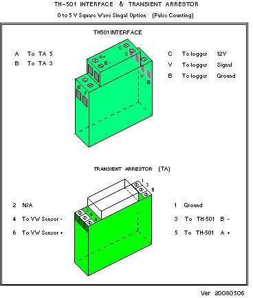
2 TABLE OF CONTENTS 1. INTRODUCTION PRECIPITATION GAUGE Principle of Operation Why is it used Advantages INSTALLATION Foundation considerations Plan height of collection inlet Locate gauge away from structures and objects Pedestal installation Precipitation gauge installation Electrical hookup Antifreeze - as needed Hydraulic Oil to Eliminate Evaporation Loosen Setscrew on transducer Replace gauge cover Install Alter Wind Screen (see Section 4) Hook up data logger and begin readings REFERENCES MOUNTING INSTRUCTIONS FOR WIND SHIELD MAINTENANCE Tools needed Service interval Servicing Check function of transducer Removing and replacing transducer Rust protection maintenance DRAWINGS / DIAGRAMS / FIGUERS Gauge vertical cross section shows parts Connection of TH501 Interface & transient arrestor Concrete foundation block Gauge with 1-m pedestal and Alter windscreen
3 1. INTRODUCTION - PRECIPITATION GAUGE 1.1. Principle of Operation The T-200B Series Precipitation Gauges are weighing bucket precipitation gauges. They are available in 600-mm, 1000-mm and 1500-mm capacity versions. It uses a precision vibrating wire (VW) transducer to weight and determine the precipitation collected. The collection container in the T-200B Series gauge is suspended from three points, each supporting 1/3 of the weight. With this type of set-up there are options available to measure precipitation with up to triple redundancy. With equal load distribution, 1, 2 or 3 VW transducers, form now on referred to as sensors, can be used to measure total precipitation and rate of precipitation. The use of extra sensors provides backup and redundancy in case one transducer stops recording. As long as 1 of the sensors is recording the precipitation rate and total will be recorded. With proper care sensors have been shown to record for more than 30 years without failing. The Sensor was developed in the 1960 s at GEONOR s then parent research foundation, The Norwegian Geotechnical Institute (NGI.) Bakkehøi 1, et al (1985). NGI used the Sensor in the T-200B gauge to measure rain and snow precipitation. NGI developed the gauge due to the need for automatically recording precipitation for avalanche research Why it is used Since its introduction in 1985, based on the results of extensive tests by the World Meteorological Organization (WMO) it was adopted by several Scandinavian meteorological services. Starting in the late 90 s U.S. and Canadian agencies have tested the gauge extensively with good results. Consequently it has seen increasing use in North America Benefits of using Vibrating Wire Transducers The Sensor has certain advantages over other types of load transducers and counting systems used in precipitation gauges: (1) Sensitivity better than 0.1 mm. (2) It has little temperature sensitivity. (3) It has no moving parts. (4) Very low power consumption. (5) The pulse signal can be transmit by cable over 1 km. (6) Data Acquisition Systems can easily log the 0 to 5 V signal with the TH-501 Interface. (7) Exceptional Long-term drift free performance measured by a 27-year test at NGI. 1 See References Section 3. 3
4 2. INSTALLATION IMPORTANT: A solid foundation and rigid pedestal are needed for proper gauge performance. We recommend using a GEONOR pedestal Foundation considerations in soil, on rock, or on a structure Regardless of whether the pedestal is installed in soil, on rock or on a structure, the pedestal must be rigid enough to prevent movements and vibrations due to wind, frost heave, loosening of soil, etc Plan height of collection orifice above anticipated snow depth With the foundation flush with ground, and using the 1-m pedestal the inlet on the; T-200B (600-mm capacity) will be approximately 1.75-m above ground. T-200B-M (1000-mm capacity) will be approximately 1.75-m above ground. T-200B-MD (1500-mm capacity) will be approximately 2.05-m above ground It is recommended to install the gauge so the inlet is at least 50 cm (20 inch) above the anticipated snow depth. For deeper snow a 2.5 m pedestal is available or the concrete foundation can be elevated. (Customized pedestals are available.) 2.3. Locate gauge away from structures and objects For best results, locate the gauge where the wind is least affected by structures. i.e. buildings, cliffs, and trees, etc. A minimum of 45 from the top of the inlet to open sky should be observed Attaching pedestal to foundation. The pedestal will be attached to the foundation with 4 anchor bolts. The bolts should be oriented in a North South & East West cross (see Fig 7.6). Make sure bolts are set vertically. Distance between N - S bolts should be 225 mm and 225 mm between E - W bolts. A wood template can be helpful in positioning the anchor bolts properly (see Fig. 7.6) Anchor bolt size, length & material ⅞, ¾ or 20-mm Ø galvanized or stainless steel threaded anchor bolts at a minimum length of 375 mm (15 inch). Make sure to leave at least 150 mm (6 inch) of exposed thread above foundation surface for to mount pedestal. 4
5 Concrete foundation The concrete foundation block (Fig. 7.6.) must remain steady. As a general guideline, see dimensions in (Fig. 7.6). The size and depth depends mostly on frost depth and the strength of the soil. Other factors may come into play at different location. Movement of the gauge may lead to errors in the data Excavation depth Excavate deep enough to avoid movement from frost heave or dynamic forces caused by wind, etc. As a general guideline excavate 600 to 1000 mm (24 to 40 inch) deep Size of concrete block foundation The height of the block can extend from flush with the ground to any required height depending location. A typical concrete foundation block width is 600 mm (24 inch) square Rock foundation On a competent rock surface, drill holes for anchor bolts (see sec ). Grout the anchor bolts in place at minimum depth of 200 mm. Make sure there is sufficient thread to mount the pedestal,at least 150 mm (6 inch) (see Fig. 7.7.) Pedestal Installation IMPORTANT: A stable pedestal is required for accurate data. If there is movement of the gauge your data may be affect Pedestal details We recommend the T-200B gauge be mounted on a GEONOR pedestal. GEONOR provides galvanized steel pedestals in 1 m and 2.5 m heights. *Custom lengths are available 5
6 Installing pedestal Mount the reaction nut, lock washer and washer on anchor bolt approx 1 above the surface (see Fig 7.7). *Do not let pedestal rest on concrete base. Using the level, adjust the 4 reaction nuts so they are level and add the lock-washers and washers. When mounting pedestal, the 3 taped mounting holes on top of the pedestal should form a triangle pointing south (See photo 2-2). Make adjustments to level gauge and install upper washers, lock-washers, and nuts on anchor bolts. Tighten and check that the pedestal is rigid and level. Make adjustments if necessary. 6


7 2.5. Precipitation Gauge installation Remove gauge cover To remove the cover, release the 3 clamps around the base and lift it straight up to clear the frame. NOTE: Press hook into locking lugs to keep them from catching on base. (See photo 2-1) (Photo 2-1) Placing gauge on pedestal Align support holes in the base of gauge with mounting holes on top of pedestal (See photo 2-3). This places 1 Sensor at the northern point. (Photo 2-2 Pedestal) (Photo 2-3 Gauge frame on Pedestal) 7
8 Insert mounting bolts Insert the 3 M8x1 bolts through the black washers into the support holes in the base and screw into pedestal. Do not tighten bolts leave space to adjust level orientation of gauge. Level the gauge by using the level supplied and adjusting the leveling screw located under the gauge. When the gauge is level tighten the 3 mounting bolts Install transducer/s & support chains IMPORTANT: The Sensor has a setscrew on the side which helps protect it. The screw must be loosened or removed for the sensor to work. If using 1 sensor, install it at the northern support point. Install support chains in the other 2 support points. If this is a 3-sensor unit, install sensors and make notes of each location. Make sure the wires from sensor are on the same side as the hole in the rim. Connect S-hooks at bottom of sensors and chains to support dish through predrilled holes. Place level across support dish. By turning the black knurl nuts on the sensors and chains fine-tune the level of the support dish Install container in support dish Carefully place the container in the support dish making sure it sits snug. Align mark on bucket (black dot) with the location of similar mark at one of the support points. This is to ensure similar installation when the container is removed and replaced. Check level by placing the level on the container and adjusting the black knurl nuts again Electrical hookup Connect Sensor to Transient Arrestor (TA) on rim Line up wire coming from top of the sensor with opening in support rim so wire comes straight up through the rim. *Do not bend wire in more than 3-cm radii and do not clamp the wire to the rim of the gauge without leaving enough slack (see photo 2-4). Connect wire to green transient arrestor box on the support rim, red (+) to terminal 6, and black (-) to terminal 4. Use wire clips or cable ties to keep in place. 8
 2.6.2. Connect wires from Transient Arrestor to Interface (TH501) The wires should be properly shielded and be suitable for the environment to which it will be exposed.")
9 IMPORTANT: Leave enough slack in the wire so it feeds straight up through the hole in the rim and does not cause the sensor to move. (Photo wire from sensor) Connect wires from Transient Arrestor to Interface (TH501) The wires should be properly shielded and be suitable for the environment to which it will be exposed. Geonor can supply any length cable required. Pass cable through the base of the gauge and the strain-relief connector supplied. Strip wires to appropriate length. We suggest removing the jacket once inside the gauge for easier handling, especially if using a multipair cable. Run wires up gauge support through an opening in rim to Transient Arrestor. Connect (+) to terminal 5 and (-) to terminal 3. (See Fig. 7.2.). Repeat for each Sensor. Remove slack and tighten strain-relief connector. The transmission distance between gauge and data collection terminal can be up to 1 km. (3000 ft) Over voltage protection ground If you are using a data logger it is suggested grounding the shielding at the data logger, not at the Transient Arrestor. Do not ground at both ends Add antifreeze as needed When the gauge is operating below 0 C, an antifreeze blend must be added to keep collected precipitation in a liquid state. If the precipitation freezes the sublimation may occur and eventually the container may break. It is important to notice that the capacity of the collected precipitation is decreased when antifreeze is added. The antifreeze becomes a part of the total volume collected. A blend of Propylene glycol 2 and Methanol 2 (40/60) is used by The US Climate Reference Network (USCRN). This blend is used to make the antifreeze and H2O similar in density preventing stratification. Stratification will lead to the formation of ice. Tables in the following sections show the amount of Propylene glycol needed to keep the collected precipitation from freezing at various temperatures. Other antifreeze solutions have been used successfully. 2 Check with local regulations regarding disposal. 9
10 Antifreeze quantities required for below freezing temperatures. Antifreeze, at a 40/60 ratio can be purchased from Greenway Chemical Co. T-200B mm gauge collection container max capacity of 12 liters. T-200B-M mm gauge collection container max capacity of 20 liters. T-200B-MD mm gauge collection container max capacity of 30 liters. Antifreeze Solution Propylene Glycol (40%) / Methanol (60%) Antifreeze as % of total capacity Freezing Point ( F) Freezing Point ( C) Add thin layer of Oil to Eliminate Evaporation To eliminate evaporation it is essential to use oil in both winter and summer. Add 0.4 liters oil. We recommend the Low Pour Hydraulic Oil from Lubriplate Co. Other oils have been used. It must not become viscous in the temperature ranges anticipated. It is recommended to change the oil at least once a year to avoid deterioration, which can result in evaporation of collected precipitation Loosen Setscrew on transducer *If you have not already installed sensor and support chains, go to section before continuing. Unscrew the setscrew at least 4 revolutions to keep it clear of the vibrating wire. It can be removed completely or left in place after loosening. If left in place, wrap the electrical that came with the sensor around the sensor and setscrew again to keep it in place. We recommend keeping the setscrew tight until maintenance has been completed Replace gauge cover Replace gauge cover and snap the 3 clips in place. NOTE: The clips fasten to sections of the base with a lip. Look or feel for theses sections. 10
11 2.11. Install Alter Type Wind Screen (see section 4, p.13) To prevent undesirable effects of wind turbulence around the gauge, a Wind Screen should be installed. The GEONOR pedestal has Wind Screen mounts on the pedestal. Using the Geonor Alter Wind Screen assures a proper installation at the specified, 13-mm height above the top of the gauge orifice. (See Section 4, p. 13) Install the Alter windscreen so the blades are approximately 13-mm above the top of the T-200B inlet Connect data logger or manual read-out unit and begin readings The Sensor is audible when power is supplied. Each transducer is slightly different but the approximate range is from 1000 Hz when empty to 3000 Hz with a full container. To calculate the amount of precipitation in cm from the frequency, use the following formula. Each sensor comes with its own calibration sheet specific for that sensor. Where: P = A (f f0) + B (f f0)² P = precipitation (in cm) f = frequency reading (Hz) A = Calibration constant, given B = Calibration constant, given f0 = frequency with empty bucket at calibration (Hz), given 11
12 3. REFERENCES Bakkehøi, Steinar; Kjell Øien and E. J. Førland (1985) An Automatic Precipitation Gauge based on Vibrating-Wire Strain Gauges, Nordic Hydrology No. 16, pp Tunbridge, Lloyd and Kjell Øien (1988) The advantage of Vibrating Wire Instruments in Geomechanics, 2 nd Intl. Symposium on Field Measurements in Geomechanics, Balkema, Rotterdam, ISBN Also publ. In Norwegian Geotechnical Institute (NGI) internal report April
13 4. INSTRUCTIONS FOR ALTER WINDSCREEN If using a double Alter windscreen, it requires the installation of cement foundations for the 8 outer Alter windscreen posts. A diagram and dimensions can be found on page 17. We suggest installing the pedestal first and use the horizontal sections with the Kee-Klamp to hold 4 of the vertical post in place while cement cures. Important! Do not forget to slide the inner Kee-Klamp on the horizontal section first. INNER ALTER WINDSCREEN PARTS 1. Blades (qty 32) 2. Spacers (qty 24) 3. Ring segments (qty 4) 4. Ring segment connectors (qty 4) 5. Kee-Klamps for ring segments (qty 4) 6. Kee-Klamps, 90 pipe fitting (qty 4) 7. 2-ft galvanized pipe, (thread on one end) (qty 4) 8. 3-ft or 4-ft galvanized pipe, (no thread) (qty 4) OUTER ALTER WINDSCREEN PARTS 1. Blades (qty 64) 2. Spacers (qty 48) 3. Ring Segments (qty 8) 4. Ring Segment connectors (qty 8) 5. Kee-Klamps for ring segments (qty 8) 6. Kee-Klamps, 90 pipe fitting (qty 8) 7. Kee-Klamps, outer alter footings (qty 8) * 8. 4-ft galvanized pipe, threaded on one end (qty 4) 9. 3-ft or 4-ft galvanized pipe, no thread (qty 4) ft galvanized pipe, vertical support of outer Alter, no thread (qty 8) ** * Kee-Klamp footings use 18 x ½ bolts, nuts and lock-washers to mount (see p.18). ** The vertical support may require adjustments in length depending on the final height of the gauge inlet and the surrounding terrain. Standard inlet height is approximately 1.75-m (5.75-ft) above the surface. Double Alter windscreen requires both the Inner and Outer Alter windscreen. 13
14 1. Mark 500-mm from the threaded end on the horizontal pipes for Inner Alter and mark 1000-mm for Outer Alter. 2. Mount connectors for ring segment on vertical sections of pipe. Mark 817- mm below the connector by wrapping tape around the pipe several times. This marks the level of the Kee-Klamp. (See photo 4-1). Connectors for outer Alter can be mounted at a later time. 14
15 3. Insert horizontal tubes into the threaded fittings on the pedestal. Tighten with pipe wrench. 4. Slide the Kee-Klamps on so the inside edge lines up with the 500-mm mark and 1000-mm mark if applicable. 5. Align the clamps vertically and tighten nut with Allen key supplied. Adjustments will to be made later. 15
16 6. Insert vertical pipes for Inner Alter in Kee-Klamp with connector for ring at top. The tape will rests on the Kee-Klamp. 7. Lay ring segments of inner Alter down and attach a ring connector to end of each segment. Slide the blades and spacers on in order shown below. Keep the channels of the blades facing outward. Connect the segments to complete a full circle. (Note: The ring connectors and the ring slot A act as spacers.) 8. Place the ring in the slots of the Kee-Klamp (photo 4-1) on the vertical pipes. (Note: Blades not shown) 16

17 9. Install Kee-Klamps on top of vertical pipes. Photo Make adjustments. 11. Arrange the 8 ring segments for outer Alter and follow steps to install blades, spacers and ring connector like step With 3 or more people you can connect the 8 segments to form the complete the ring and put it in place. If not connect 4 sections to make a half circle and connect the 2 halves in place. 17
18 18
 0-27 mm Container for disposal of anti-freeze mixture (12 liter minimum) Funnel Measuring cylinder, 1 liter Supplied tools")

19 5. MAINTENANCE 5.1. Tools needed Screw driver, 4-mm blade Hammer Adjustable spanner (wrench) 0-27 mm Container for disposal of anti-freeze mixture (12 liter minimum) Funnel Measuring cylinder, 1 liter Supplied tools Siphon Level 5.2. Service interval Service the gauge when the container needs to be emptied. Inspection is recommended 2 times a year. Automatic emptying systems have been used. Please contact us for more information Servicing You may find servicing the gauge easier by removing the windscreen from 3 of the 4 posts as shown below. (Photos 5-1 & 5-2) Disengage the 3 spring fasteners holding gauge cover to the base and remove the housing (see Section ). Tighten the setscrew of the Sensor to avoid damaging the vibrating wire. Antifreeze mixtures are toxic. Do not attempt to suck on tube to start flow. NOTE: If the oil in the container does not need to be replaced there is no need to remove it. Use the siphon pump supplied or something similar to remove liquid from container or remove manually. Remember a full container is very heavy. 19
20 Using the siphon pump supplied, place the shorter end at the bottom of the bucket. Holding the receptacle at a lower level than the bucket pump the siphon until flow starts. Once the flow has started there is no need to pump. Simply wait until you have removed the proper amount. You can empty the bucket by hand. Be careful not to overload the VW load cell or subject it to any shock. Clean bucket and add required anti-freeze mixture and oil. Replace carefully in the weighing dish aligning the black dot on the rim of the bucket with the one on the support rim. ***Loosen the set-screw on transducer*** Replace the gauge cover and lock 3 clamps Checking the function of the transducer Empty bucket check Level the bucket accurately (see Sections & ). Check the frequency with an empty bucket (fo-value) using a datalogger or a GEONOR P-520N portable frequency counter 3. Compare with the f0-value on the calibration certificate for the transducer. If the difference is equal or less than 10 Hz no adjustment is necessary. If the difference exceeds10 Hz a new value for constant A should be calculated. Use the new f0 and the new A in your calculations. Formula for calculating a new constant A with new fo A' = A + 2B(f0' f0) Where A' and f0' are new values, and A, B and f0 are the original calibration values. (See Section or calibration sheet) Check with precipitation in the bucket Fill the container with 1-kg of water. If the water is free of air this equals a volume of 1 liter. (Water from the tap can contain considerable air, which must be taken into account. Boiling for 10 minutes can remove most of the air.) 1 kg (1 liter) of water represents exactly 50 mm of precipitation. Recalibrate the Sensor if it differs by more than 0.5% from the value on the calibration sheet. 3 GEONOR model P-520M portable frequency counter. 20
21 GEONOR offers calibration services Removing and replacing transducer Remove gauge cover Tighten setscrew on VW load cell Lift out container carefully Disconnect electrical leads from the transient arrestor Unhook the S-hook from the support dish Hold the Sensor and remove knurled nut from top of adjustment screw Remove the Sensor from square guide in the support rim. Install a new Sensor in the reverse order (see Section ) IMPORTANT: The support dish must be free to swing in all directions without noticeable resistance. Resistance in the support links can contribute to error especially with low weights in the container. When installing a new or recalibrated Sensor, use the new values for A, B and f0. These are given on the calibration sheet with the Sensor Rust protection maintenance For added protection, apply two layers of a rust preventing coating such as paint, zinc-galvanizing spray or similar on all threaded parts of the pedestal and Wind Screen. 21
22 6. DRAWINGS / DIAGRAMS / FIGURES 6.1. T-200B Gauge vertical cross section shows parts Connection of TH501 Interface & transient arrestor Alter-shield details Concrete foundation block Gauge with 1m pedestal and Alter Windscreen
23 6.1 23

24 6.2 24
25 6.3 25
26 6.4 26
#TL T EA888 GEN 3 FUELING SYSTEM/ INSTALLATION INSTRUCTIONS
 #TL100069 2.0T EA888 GEN 3 FUELING SYSTEM/ INSTALLATION INSTRUCTIONS Notes: These instructions were written for a North American specification MkVII GTI. Other models, like the Golf R, are similar. When
Installation Instructions
 Approx. Install Time 3Hrs 00Min Installation Instructions Vehicle Application Year: 2013-2017 Make: Ram Model: 2500/3500 Diesel Engine: 6.7L Cummins Tools Required 7mm, 8mm, 10mm,& 13mm Wrench & Socket
Installation Instructions Table of Contents
 Installation Instructions Table of Contents Pre- Installation of Garage Storage Lift 2 Layout the Garage Storage Lift 3 Installing the strut Channels 3 Install the Drive Assembly 5 Install the Drive Shaft
CS Fiber Optic Splice Case. Instruction
 3 2179-CS Fiber Optic Splice Case Instruction 2179-CS Fiber Optic Splice Case Description 1.0 General 1.1 The 3M 2179-CS Fiber Optic Splice Cases are closures that can be used in buried, underground, aerial,
Sherco Setup and Lubrication Guide
 Sherco Setup and This guide is designed to provide the Sherco owner with instructions on how to: Set up a new bike Clean and re-oil the air filter Change the transmission oil Change the fork oil Repack
HYDRAULICS. TX420 & & lower. Hydraulic Tandem Pump Removal. 4. Remove the LH side panel (Fig. 0388).
.") TX420 & 425 240000299 & lower 4. Remove the LH side panel (Fig. 0388). Hydraulic Tandem Pump Removal Note: Cleanliness is a key factor in a successful repair of any hydraulic system. Thoroughly clean all
TX420 & 425 240000299 & lower 4. Remove the LH side panel (Fig. 0388). Hydraulic Tandem Pump Removal Note: Cleanliness is a key factor in a successful repair of any hydraulic system. Thoroughly clean all
Hornby Railroad Crosti 9F EM Finescale Conversion.
 Hornby Railroad Crosti 9F EM Finescale Conversion. Before you start, it is a good idea to have some small containers or snap top poly bags to put screws and components in for safe keeping...much better
METEOROLOGICAL INSTRUMENTS
 METEOROLOGICAL INSTRUMENTS INSTRUCTIONS PRECIPITATION GAUGE MODEL 50202 / 50203 R.M. YOUNG COMPANY 2801 AERO PARK DRIVE, TRAVERSE CITY, MICHIGAN 49686, USA TEL: (231) 946-3980 FAX: (231) 946-4772 WEB:
RST INSTRUMENTS LTD.
 RST INSTRUMENTS LTD. Vibrating Wire Crackmeter VWCM Instruction Manual Copyright 2017 Ltd. All Rights Reserved. Ltd. 11545 Kingston St., Maple Ridge, B.C. Canada V2X 0Z5 Tel: (604) 540-1100 Fax: (604)
MICROGUARD 500 EXTENSION REEL TRAINING MANUAL. Greer Company. Greer Company Crane Systems 1 OF18
 MICROGUARD 500 EXTENSION REEL TRAINING MANUAL 1 OF18 TABLE OF CONTENTS MICROGUARD 500 SERIES EXTENSION REEL TRAINING MANUAL EXTENSION REEL OVERVIEW...3 REEL-OFF CABLE LAYERING...3 CHECKING THE REEL-OFF
INSTALLATION INSTRUCTIONS
 INSTALLATION INSTRUCTIONS PERFORMANCE AT THE WHEELS KIT W120-22, W120-23 1964 1/2-69 MUSTANG Thank you for choosing STAINLESS STEEL BRAKES CORPORATION for your braking needs. Pleases take the time to read
Vehicle Cooling System
 Engine coolant does more than prevent freezing and boiling of the engine cooling system; coolant also lubricates the water pump and provides corrosion protection for aluminum radiators and engine components.
Installation Manual. For. Trident Boat Lifts
 Installation Manual For Trident Boat Lifts Page 2 Safety Precautions 1. Your boat lift is a heavy duty piece of equipment. It is important that all persons that may operate this unit have read and understood
Exhaust Heat Shield Instructions ND
 Exhaust Heat Shield Instructions ND 2016 + Thank you for purchasing the Track Dog Racing Exhaust Heat Shield for the 2016 to Present Mazda MX-5. Our TDR Heat Shield is designed to help maintain lower temperatures
2013 RT / 2014RT / 2015 RT - Shock Spring Adjuster Installation Instructions
 2013 RT / 2014RT / 2015 RT - Shock Spring Adjuster Installation Instructions Billet Aluminum Adjusters (2) Shock Spring Compressors (Optional) Spanner Wrench (1) BajaRon Decals Not Shown (4) Adjuster Scuff
Method. Remote solenoids. QuickInstall Guide
 Remote solenoids Where remote solenoids are specified a single supply pipe is taken from the pump, or tap supply and connected to a single entry point on the remote solenoid manifold. From each solenoid
INSTALLATION MANUAL. Thunderstone Manufacturing LLC 3400 West O Street Lincoln, NE (Fax)
") INSTALLATION MANUAL August 7 th 2018 43 /48 /50 2011 and Older Timpte STD/Split 36 Style Hopper Trailers with Roller Bearing Doors Kit #101533 for 96w & Kit #101534 for 102w Thunderstone Manufacturing
INSTALLATION MANUAL August 7 th 2018 43 /48 /50 2011 and Older Timpte STD/Split 36 Style Hopper Trailers with Roller Bearing Doors Kit #101533 for 96w & Kit #101534 for 102w Thunderstone Manufacturing
3 Axles and brakes. 3.1 Function and construction of the axles Construction Function
 3 Axles and brakes 3.1 Function and construction of the axles 3.1.1 Function Each wheel has an independent suspension system in the axle body (1), so that individual wheel suspension is provided. The swinging
Read this entire manual before operation begins.
 Read this entire manual before operation begins. Record below the following information which is located on the serial number data plate. Serial No. Model No. Date of Installation Contents Specifications.............
Automatic Roof Hatch Opener
 Automatic Roof Hatch Opener Installation Guide REQUIRED TOOLS (These tools are required to complete the installation) Cordless Drill 1/8 1/4 Drill Bits 1/8 Pin Punch #2 Philips Bit Rachet Sharpie Hammer
9'8" x 9'8" (8,8 m2)
") 9'8" x 9'8" (8,8 m) 007-CH 007 - CH GB May we congratulate you on your new greenhouse US Dear DER Customer! CUSTOMER The Congratulations assembly of on your purchasing new house your new requires greenhouse.
9'8" x 9'8" (8,8 m) 007-CH 007 - CH GB May we congratulate you on your new greenhouse US Dear DER Customer! CUSTOMER The Congratulations assembly of on your purchasing new house your new requires greenhouse.
Detailed Assembly Instructions. ATS Evacuated Tube - Solar Panel Units ATS10 / ATS20 / ATS30
 Detailed Assembly Instructions ATS Evacuated Tube - Solar Panel Units ATS10 / ATS20 / ATS30 Release: 2/2012 1 ATS-10, ATS-20, and ATS-30 tube collectors are all setup using a similar method. Carefully
A B C D E F. Tools Required (supplied by others)
") Page 1 of 17 Parts List Below Deck Automatic Retractable Security Cover Kit (1) Tube End Bearing Plate (A) (1) Rope Reel and Cover Drum Motor Assembly (B) (1) Cover Drum (1) Pulley Support Channel (2)
Page 1 of 17 Parts List Below Deck Automatic Retractable Security Cover Kit (1) Tube End Bearing Plate (A) (1) Rope Reel and Cover Drum Motor Assembly (B) (1) Cover Drum (1) Pulley Support Channel (2)
Replacing MK4 Golf/Jetta radiator mounts in-car
 Replacing MK4 Golf/Jetta radiator mounts in-car This is a guide to replacing the radiator mounts in a MK4 Golf/Jetta. This involves moving the core support to the service position which allows you to do
The H-MAC Heavy Metal Articulating Chassis Construction Guide
 The H-MAC Heavy Metal Articulating Chassis Construction Guide The Heavy Metal Chassis is constructed with two identical drive modules built using 10 mechanical sub-assemblies. The drive modules are integrated
AUTO REWIND AIR HOSE REEL
 Model #s 46845, 46848 AUTO REWIND AIR HOSE REEL OPERATOR S MANUAL STORE THIS MANUAL IN A SAFE PLACE FOR FUTURE REFERENCE!? NEED HELP? Save time, contact us first. 888-648-8665 support@tekton.com WARNING:
JEEVES. JEEVES Installation Manual. Installation Manual The Easiest Do-It-Yourself Dumbwaiter on the Market
 1 888-323-8755 www.nwlifts.com JEEVES Installation Manual The Easiest Do-It-Yourself Dumbwaiter on the Market This manual will cover the installation procedure step-by-step. The installation of this dumbwaiter
920 Remote Control Switches
 920 Remote Control Switches REMOTE CONTROL SWITCHES Service Bulletin This service bulletin for ASCO 920 Remote Control Switches explains how to replace the main s, operator coil, control s, and how to
BELT DRIVE SYSTEM TROUBLESHOOTING CHART CAUSES CORRECTIVE ACTION ENGINE RUNS BUT PADDLES DO NOT TURN
 ELT DRIVE SYSTEM TROULESHOOTING HRT USES ORRETIVE TION ENGINE RUNS UT PDDLES DO NOT TURN elt jumps off the drive pulleys. Inspect the belt for damage. Replace belt if needed. heck belt alignment. Idler
RST INSTRUMENTS LTD.
 RST INSTRUMENTS LTD. MEMS In-Place Inclinometer System Instruction Manual Copyright 2018 Ltd. All Rights Reserved. Ltd. 11545 Kingston St., Maple Ridge, B.C. Canada V2X 0Z5 Tel: (604) 540-1100 Fax: (604)
INSTALLATION INSTRUCTIONS
 INSTALLATION INSTRUCTIONS 2102 LOWERING SPINDLE ASSEMBLY 1998-UP CHEVROLET / GMC BLAZER / X-TREME / JIMMY / ENVOY 2 Wheel Drive Congratulations! You were selective enough to choose a BELLTECH PRODUCT.
INSTALLATION INSTRUCTIONS FORD F-150 2WD & 4WD RETAINS FACTORY TOW HOOKS PART #P3063
 INSTALLATION INSTRUCTIONS FORD F-150 2WD & 4WD RETAINS FACTORY TOW HOOKS PART #P3063 PARTS LIST: 1 Grille Guard 2 10-1.5mm Nylon Lock Nuts 1 Driver/Left Frame Mounting Bracket 4 12mm Plastic Washers 1
Installation Instructions
 Roller & Roman Shades Lifting Systems Cassette and Sure-Lift EZ Lift Cordless EZ Pull Standard and Cassette R-Series Clutch SL-Series Clutch Spring Roller Fascias and Valances 3, 4 Flat and 4 Curved Fascia
Side Dump Tarp System Driver or Passenger Stowing Non-Sealed applications
 Roll Rite, LLC and its entire staff would like to not only Thank You but congratulate you on your purchase of one of what we feel to be the finest line of tarping systems in the industry. Side Dump Tarp
WARNING. When installed in accordance with these instructions, the front protection bar does not affect operation of the SRS airbag.
 Part Number: 343870 F/Kit 17557 Product Deluxe Combination Winch and Non Winch Bull Bar Description: Suited to Nissan XTERRA 05ON USA Only vehicle/s: WARNING REGARDING VEHICLES EQUIPPED WITH SRS AIRBAG;
Suzuki Samurai to Toyota Front Spring Swap Kit, with Missing Link Shackles (SKU#SSP-TSFM) Installation Instructions
 Installation Instructions") Suzuki Samurai to Toyota Front Spring Swap Kit, with Missing Link Shackles (SKU#SSP-TSFM) Installation Instructions CAUTION: Safety glasses should be worn at all times when working with vehicles and related
Suzuki Samurai to Toyota Front Spring Swap Kit, with Missing Link Shackles (SKU#SSP-TSFM) Installation Instructions CAUTION: Safety glasses should be worn at all times when working with vehicles and related
How to build a Hydraulic Ram Pump By Seth Johnson Land To House Version 1.1
 Seth Johnson How to build a Hydraulic Ram Pump By Seth Johnson Land To House Version 1.1 History: A man named John Whitehurst first created the Hydraulic Ram Pump in 1772. That means that this ingenious
VIBRATING WIRE DISPLACEMENT TRANSDUCERS. JM Series. Roctest Limited, All rights reserved.
 INSTRUCTION MANUAL VIBRATING WIRE DISPLACEMENT TRANSDUCERS Series Roctest Limited, 2014. All rights reserved. This product should be installed and operated only by qualified personnel. Its misuse is potentially
AmTryke Adult Recumbent Model HP1000 #50-HC-1000
 AmTryke Adult Recumbent Model HP1000 #50-HC-1000 TOOLS Needed for Assembly 5 mm Allen Wrench 8 mm Socket or Wrench 10 mm Socket or Wrench 14 mm Socket or Wrench 15 mm Socket or Wrench 22 mm Socket or Adjustable
Torqueflite Manual/Automatic Valve Body
 TCI 122400 Torqueflite Manual/Automatic Valve Body This valve body can be installed in a few hours by carefully following directions. Read all instructions first to familiarize yourself with the parts
2177 MOISTURE TESTER OPERATION INSTRUCTIONS VERSION 1.2
 2177 MOISTURE TESTER OPERATION INSTRUCTIONS VERSION 1.2 Contents Page 2 Contents 1.0 COMPONENT LIST... 3 2.0 INSTALLATION... 4 2.1 Installation of the Moisture Sensor... 4 2.2 Installation of the Display
LK Shunt Cabinet VS2, Shunt Cabinet VS2 Prefab
 LK Shunt Cabinet VS2, Shunt Cabinet VS2 Prefab Design LK Shunt Cabinet VS2 The LK Shunt Cabinet VS2 is designed to be used when you wish to hide the LK Manifold RF and LK Manifold Shunt VS2. The cabinet
Suzuki GS1000G fork seal replacement
 Suzuki GS1000G fork seal replacement Before you start you require: 1) To read workshop service manual for your model 2) Socket allen key M8 3) Torque wrench 4) Special tool to hold inner, make your own,
RoughDeck TM FXB Flexure Base Floor Scale. Installation/Operation Manual
 RoughDeck TM FXB Flexure Base Floor Scale Installation/Operation Manual SM 32958 13 Contents 1. Introduction... 1 1.1 Scale Components... 1 1.2 Operating Requirements... 2 1.3 How Flexure Levers Work...
DEFENDER SERIES. 5 Gallon, Double Walled, Field Replaceable Spill Container Model Series INSTALLATION, OPERATION, & MAINTENANCE
 DEFENDER SERIES 5 Gallon, Double Walled, Field Replaceable Spill Container Model 705-550 Series INSTALLATION, OPERATION, & MAINTENANCE Franklin Fueling Systems 3760 Marsh Rd. Madison, WI 53718 USA Tel:
Installation Instructions LamboStyleDoors (The instruction are to be used as a reference. Please repeat for both doors)
") Installation Instructions LamboStyleDoors (The instruction are to be used as a reference. Please repeat for both doors) Mercedes C-Class Sport coupé type W203 Part number 500 25 009 Pre installation check
Installation Instructions LamboStyleDoors (The instruction are to be used as a reference. Please repeat for both doors) Mercedes C-Class Sport coupé type W203 Part number 500 25 009 Pre installation check
CONTENTS. Product Features and Specifications Installation Requirement Installation Exploded View Operation Instruction...
 1 CONTENTS Product Features and Specifications... 3 Installation Requirement... 5 Installation... 6 Exploded View... 20 Test... 22 Operation Instruction... 25 Maintenance... 26 Trouble Shooting... 27 Parts
Installation Instructions LamboStyleDoors (The instruction are to be used as a reference. Please repeat for both doors)
") Installation Instructions LamboStyleDoors (The instruction are to be used as a reference. Please repeat for both doors) Pre installation check list: - Double check vehicles data with TUV certificate -
Installation Instructions LamboStyleDoors (The instruction are to be used as a reference. Please repeat for both doors) Pre installation check list: - Double check vehicles data with TUV certificate -
s_enn Exterior Stainless Steel Shading System by Draper
 Installation Instructions s_enn Exterior Stainless Steel Shading System by Draper Caution 1 Never push the bottom rail of the system up by hand. This can cause irreparable damage. Access equipment must
accqpulse Velocity Profiler Sensor Installation Guide
 accqpulse Velocity Profiler Sensor Installation Guide Instruction Sheet #69-7403-012 Released May 2016 Overview This instruction guide is for the installation of the accqpulse shallow water and deep water
The Sands Mechanical Museum
 The Sands Mechanical Museum How to Change Your Oil It is more difficult to change the oil in a Lotus Elise because the oil plug and filter are difficult to access. They are located behind an access panel.
FS II - Mounting Instruction. 1 General 2. 2 Pile driving (Ramming) 3. 3 Mounting individual assemblies 4. 4 Components list 5
 3. 3 Mounting individual assemblies 4. 4 Components list 5") FS II Mounting Instruction CONTENTS Page 1 General 2 2 Pile driving (Ramming) 3 3 Mounting individual assemblies 4 4 Components list 5 5 Torque specifications 9 6 Module mounting 9 7 Cable mounting 10
FS II Mounting Instruction CONTENTS Page 1 General 2 2 Pile driving (Ramming) 3 3 Mounting individual assemblies 4 4 Components list 5 5 Torque specifications 9 6 Module mounting 9 7 Cable mounting 10
First, check and record the camber and caster readings, they will be adjusted later.
 First, check and record the camber and caster readings, they will be adjusted later. The caliper-mounting bosses are machined perpendicular to the spindle so they are an excellent place for the level.
Alignment Comparison Report (May 9, 2002) PARK BRIDGE TO BRAKE CHECK (10 Mile Bridge) TRANS CANADA HIGHWAY (CCR)
 PARK BRIDGE TO BRAKE CHECK (10 Mile Bridge) TRANS CANADA HIGHWAY (CCR)") Alignment Comparison Report (May 9, 2002) PARK BRIDGE TO BRAKE CHECK (10 Mile Bridge) TRANS CANADA HIGHWAY (CCR) INTRODUCTION The Ministry of Transportation (MoT), Region 2, Highway Engineering staff were
Alignment Comparison Report (May 9, 2002) PARK BRIDGE TO BRAKE CHECK (10 Mile Bridge) TRANS CANADA HIGHWAY (CCR) INTRODUCTION The Ministry of Transportation (MoT), Region 2, Highway Engineering staff were
Z1 Motorsports 370Z/G37 Oil Cooler Kit Installation Manual
 Z1 Motorsports 2877 Carrollton Villa Rica Hwy Carrollton GA 30116 770.838.7777 Z1 Motorsports 370Z/G37 Oil Cooler Kit Installation Manual For 19, 25 and 34 Row Oil Cooler Kits Parts Included: 1 SETRAB
JEEP JK 4 LONGARM. Tools Needed: Thank you for choosing Rough Country for your suspension needs.
 921786000 Thank you for choosing Rough Country for your suspension needs. JEEP JK 4 LONGARM Rough Country recommends a certified technician install this system. In addition to these instructions, professional
INSTALLATION INSTRUCTIONS
 INSTALLATION INSTRUCTIONS PERFORMANCE AT THE WHEELS KITS W156-6 & W156-7 1965-74 MOPAR B & E BODY Thank you for choosing STAINLESS STEEL BRAKES CORPORATION for your braking needs. Pleases take the time
RS-110 Rainfall Sensor Installation Guide
 RS-110 Rainfall Sensor Installation Guide for XR440 and XR5 Data Loggers September 2015 Revision 1.1 1 Disclaimer The following warranty and liability disclaimer apply to this product. PACE SCIENTIFIC
MODEL NUMBER: MEDIUM DUTY ONBOARD AIR SYSTEM
 MODEL NUMBER: 10003 MEDIUM DUTY ONBOARD AIR SYSTEM IMPORTANT: It is essential that you and any other operator of this product read and understand the contents of this manual before installing and using
2013-UP 3500 Dodge 5 Lift Kit SRW
 92369200 2013-UP 3500 Dodge 5 Lift Kit SRW Thank you for choosing Rough Country Suspension for your Off Road needs. Rough Country recommends a certified technician installs this system. In addition to
Table of Contents WARN INDUSTRIES PAGE A1
 INSTALLATION INSTRUCTIONS AND OPERATORS GUIDE ProVantage Bucket Conversion Kit Part Number: 84133 (50 ), 83133 (54 ) and 85133 (60 ) Application: Front Mount Plow* * Not recommended for use with Center
SBS Range Rain Gauge User Manual
 SBS Range Rain Gauge User Manual PUBLISHED BY Environmental Measurements Limited (EML) 7 Jupiter Court Orion Business Park North Shields NE29 7SE United Kingdom Visit our internet pages at http://www.emltd.net
Overload Warning System DS 50
 Overload Warning System DS 50 Grove - FMTV Trouble Shooting Manual Level 1 - Basics - 1 Table of contents Troubleshooting Manual PAT Overload Warning system DS 50 Level 1 -Basics- Item Content Page 1.
Section 13. Tail Rotor Drive. RotorWay International A600 TALON Construction Manual. Section 13. Page A
 RotorWay International Page A Tail Rotor Drive Procedures covered in this section: Install driveshafts and gearboxes; install drive belt and tensioner; fabricate and install tail rotor pitch actuator arms;
Assembly Manual. 1/10th Formula 1 Car
 Assembly Manual 1/10th Formula 1 Car Center Pivot Bag 1 3374 - Center Pivot Socket 40194 - Hard Anodized Alum Pivot ball 3254-2-56 *Note - Sometimes it is helpful to slightly over-tighten the top clamp
Installation instructions for Camaro/Firebird and Nova* Windshield Wiper Systems
 Installation instructions for 1967-69 Camaro/Firebird and 1968-74 Nova* Windshield Wiper Systems The Raingear 1967-69 Camaro/Firebird and 1964-74 Nova wiper system is designed for ease of installation
COLD AIR INTAKE INSTALLATION INSTRUCTIONS
 COLD AIR INTAKE INSTALLATION INSTRUCTIONS # D760-0030 Fits: 2007-10 135i (E82, E88; with N54 engine) 2007-08 335i/xi (E90) 2007-10 335i (E92, E93; with N54 engine) Congratulations for being selective enough
SLiC Aerial Terminal and Spiral End Seal for use with AMP* Quiet Front Terminal Blocks
 SLiC Aerial Terminal and Spiral End Seal for use with AMP* Quiet Front Terminal Blocks Instructions June 2002 78-8130-2161-1-B 1 Contents: 1.0 General... 3 2.0 Kit Contents... 3 3.0 Cable Preparation...
WARNING: Only perform this installation if you are experienced, fully equipped mechanic.
 DYNATRAC V3.2 2005-Present Ford Super Duty 250/350-4x4, Front Axle, Free Spin Conversion Kit Some of the less common tools, which will be required: 6 point Spanner socket (OTC #7090-A or equivalent). These
Mi c r o Er a s e r. Conveyor Belt Cleaning System. INSTALLATION GUIDE LIB-CP-MEA Rev. 5
 INSTALLATION GUIDE LIB-CP-MEA-03-01 Rev. 5 Mi c r o Er a s e r Conveyor Belt Cleaning System Patent Pending 1110 Wright Street Marquette, MI 49855 Phone: 1-800-991-2746 Fax: 906-226-9779 www.argonics.com
1.1 Quad Valve and Tri-Valve. Contents WATER DUMP BODY O-RING EXHAUST VALVE QUAD VALVE TIE WRAP EXHAUST MAIN BODY O-RING
 Quad Valve and Tri-Valve Exhaust Assembly on Fiberglass Helmets Quad Valve and Tri-Valve Exhaust Contents QUAD-1 QUAD-2 QUAD-2 QUAD-2 QUAD-6 QUAD-7 1.1 Quad Valve and Tri- Valve Exhaust Assembly on Fiberglass
VW Surface-Mount Strain Gauge
 VW Surface-Mount Strain Gauge 52650399 Copyright 2003 Slope Indicator Company. All Rights Reserved. This equipment should be installed, maintained, and operated by technically qualified personnel. Any
INSTALLATION INSTRUCTIONS
 INSTALLATION INSTRUCTIONS INSTALLATION INSTRUCTIONS THESE INSTRUCTIONS COVER THE INSTALLATION OF THE FOLLOWING REAR DOORS WITH OUTSIDE CABLES AND MAXIMUM SECURITY LOCK: 3/4" and 1" DryFreight TODCOLD Insulated
Read this entire manual before operation begins.
 Read this entire manual before operation begins. Record below the following information which is located on the serial number data plate. Serial No. Model No. Date of Installation Contents Specifications.............
STORM Guardian. Operator s Handbook
 STORM Guardian Operator s Handbook COPYRIGHT The copyright in this document which contains proprietary information is vested in CASELLA. The contents of this document must not be used for purposes other
Personal Protection Equipment (PPE) Safety Glasses Protect eyes Welding Mask Protect eyes and face
 Safety Glasses Protect eyes Welding Mask Protect eyes and face") Table of Contents: Title Page... 1 Introduction... 3 Before Construction... 3 Equipment Needed... 3 Drawings... 4 Construction... 5 1. Cut Sheet Drawings... 5 2. Base... 5 3. Combustion Chamber... 12 4.
Table of Contents: Title Page... 1 Introduction... 3 Before Construction... 3 Equipment Needed... 3 Drawings... 4 Construction... 5 1. Cut Sheet Drawings... 5 2. Base... 5 3. Combustion Chamber... 12 4.
INSTALLATION INSTRUCTIONS
 INSTALLATION INSTRUCTIONS 6525 REAR AXLE FLIP & HANGER KIT 5 OR 6 INCH LOWERING 14&UP CHEVROLET SILVERADO / GMC SIERRA 1500 Thank you for being selective enough to choose our high quality BELLTECH PRODUCT.
Maintenance Information
 Form 16575334 Edition 1 April 2005 Electric Screwdrivers EL, EP and ET 34V DC Series Maintenance Information Save These Instructions WARNING Maintenance procedures have the potential for severe shock hazard
INSTALLATION INSTRUCTIONS
 INSTALLATION INSTRUCTIONS REAR CONVERSION KIT A111-2 (FORD 8" & 9" SMALL BEARING) & REAR CONVERSION KIT A111-3 (FORD 9 TORINO) Thank you for choosing STAINLESS STEEL BRAKES CORPORATION for your braking
AmTryke Adult Recumbent Model JT2000 #50-FC-2000
 AmTryke Adult Recumbent Model JT2000 #50-FC-2000 TOOLS Needed for Assembly 5 mm Allen Wrench 8 mm Socket or Wrench 10 mm Socket or Wrench 14 mm Socket or Wrench 15 mm Socket or Wrench 22 mm Socket or Adjustable
TABLE OF CONTENTS. Contents CONTENTS... PAGE. Jan 2006 COPYRIGHT. Tipping Bucket Rain Gauges User Manual. Tipping Bucket Rain Gauges User Manual
 Jan 2006 Contents TABLE OF CONTENTS CONTENTS................ PAGE 1. INTRODUCTION........................... 3 Tipping Bucket, Heated Tipping Bucket Rain Gauges & Rain Gauge That Meets The Requirements
CALIFORNIA TRIMMER MOWER MAINTENANCE MANUAL
 CALIFORNIA TRIMMER MOWER MAINTENANCE MANUAL 2 Table of Contents Section 1: General Information Page Handle Assembly Instructions 4 Maintenance All Models 6 Oil Change Procedures All Models 9 Height Adjustment
Written By: David Hodson
 2008-Present Scion xb Oil Change Second generation Scion xb oil change. Written By: David Hodson ifixit CC BY-NC-SA www.ifixit.com Page 1 of 19 INTRODUCTION Change the oil in your 2008 or newer Scion xb
Installation Instructions LamboStyleDoors (The instruction are to be used as a reference. Please repeat for both doors)
") Installation Instructions LamboStyleDoors (The instruction are to be used as a reference. Please repeat for both doors) Hyundai enesis Coupé type BK38 Part number 500 66 002 Pre installation check list:
Installation Instructions LamboStyleDoors (The instruction are to be used as a reference. Please repeat for both doors) Hyundai enesis Coupé type BK38 Part number 500 66 002 Pre installation check list:
RAMPAGE POWER LIFT RAMP
 RAMPAGE POWER LIFT RAMP INSTALLATION AND OPERATING INSTRUCTIONS (3/10/07) The Rampage Power Lift Ramp is the fast, easy, and safe way to load a motorcycle into a truck. One person can load or unload a
Installation Instructions LamboStyleDoors
 Installation Instructions LamboStyleDoors (The instruction refers only to one side of the car, but is valid for both sides) Preparations: (Dismantling according to the regulation of the car manufacturer)
INSTALLATION INSTRUCTIONS FORD F-150 2WD & 4WD RETAINS FACTORY TOW HOOKS PART #P3063
 INSTALLATION INSTRUCTIONS FORD F-150 2WD & 4WD RETAINS FACTORY TOW HOOKS PART #P3063 PARTS LIST: 1 Grille Guard 2 10-1.5mm Nylon Lock Nuts 1 Driver/Left Frame Mounting Bracket 4 12mm Plastic Washers 1
BEST MANAGEMENT PRODUCTS, INC. The SNOUT INSTALLATION INSTRUCTIONS U.S. Patent # Canadian Patent #
 PRODUCT NAME The SNOUT Oil-Water-Debris Separator U. S. Patent # 6126817 Canadian Patent # 2285146 MANUFACTURER Best Management Products, Inc. 53 Mt. Archer Rd. Lyme CT 06371 Phone: (800) 504-8008 Fax:
ARG100 Rain Gauge User Manual
 ARG100 Rain Gauge User Manual UM-780-001-ARG100 V1.00 PUBLISHED BY Environmental Measurements Limited (EML) 7 Jupiter Court Orion Business Park North Shields NE29 7SE United Kingdom Visit our internet
CONTENTS. This Product is Certified by CANADIAN STANDARDS ASSOCIATION and Bears the Mark:
 This Product is Listed by UNDERWRITERS LABORATORIES INC. and Bears the Mark: This Product is Certified by CANADIAN STANDARDS ASSOCIATION and Bears the Mark: SLATER SCD Installation Instructions For Self-Contained
INSTALLATION INSTRUCTIONS
 INSTALLATION INSTRUCTIONS DISC BRAKE CONVERSION KITS A121-1, A121-2, A121-3, A121-4 1967-69 Ford & Mercury Thank you for choosing STAINLESS STEEL BRAKES CORPORATION for your braking needs. Pleases take
WirelessONE. Kit INSTALLATION GUIDE. Key Fob Activated Compressor System
 Kit 25870 Key Fob Activated Compressor System MN-751 (041202) ECR 7260 INSTALLATION GUIDE For maximum effectiveness and safety, please read these instructions completely before proceeding with installation.
Tools Needed: Class 8.8 Class MM 55ft/lbs 75ft/lbs 14MM 85ft/lbs 120ft/lbs 16MM 130ft/lbs 165ft/lbs 18MM 170ft/lbs 240ft/lbs
 921788000 JEEP JK 6 LONGARM Rough Country recommends a certified technician install this system. In addition to these instructions, professional knowledge of disassemble/reassembly procedures as well as
Assembly instructions A B. A (mm) B (mm) C (mm) A A A A Walk-in Greenhouse
 B (mm) C (mm) A A A A Walk-in Greenhouse") ssembly instructions C MODEL (mm) (mm) C (mm) 907 34 90 950 689 4 9 3666 94 438 Walk-in Greenhouse Statement Dear Customer! May we congratulate you on your new Greenhouse. We feel sure that by following
ssembly instructions C MODEL (mm) (mm) C (mm) 907 34 90 950 689 4 9 3666 94 438 Walk-in Greenhouse Statement Dear Customer! May we congratulate you on your new Greenhouse. We feel sure that by following
NM-NP Pajero Rhino Heavy Duty - Two Bar Trackmount System
 NM-NP Pajero Rhino Heavy Duty - Two Bar Trackmount System Parts List Important: Please read these instructions carefully prior to installation. Please refer to your fitting instruction to ensure that the
Installation Instructions
 DODGE 20K Industry Standard Rail Custom Mounting Kit #2742 Gross Trailer Weight (Maximum)...20,000 lbs. Vertical Load Weight (Max. Pin Weight)...5,000 lbs. SYSTEM TOW CAPACITY Please note, in order to
CAT pin grabber quick change modifications.
 1 CAT pin grabber quick change modifications. Remove bucket from quick-change coupler Remove quick-change coupler and grind area shown here. Use gray plastic gage furnished with QC thumbs to determine
FULL BORE PERFORMANCE EXHAUST MANIFOLDS F-150 ECOBOOST 3.5L
 2018-01-15 FORD F150 ECOBOOST 3.5L FULL BORE PERFORMANCE MANIFOLD SET (PART #500101X) 1 FULL BORE PERFORMANCE EXHAUST MANIFOLDS F-150 ECOBOOST 3.5L INSTALLATION INSTRUCTIONS 2011-2012 FORD F150 3.5L ECOBOOST
 www.odometergears.com Mercedes-Benz Mechanical Odometer Repair This how to can be used for all mechanical repairs as the only difference will be the removal of the instrument cluster. http://www.dieselgiant.com/repairyourodometer.htm
Thank you for purchasing the Dezod Motorsports Return Fuel System for your Scion tc.
 Thank you for purchasing the Dezod Motorsports Return Fuel System for your Scion tc. We took much pride in putting together a fuel system that would deliver a maximum amount of fuel as simply as possible