Thank you for purchasing the Dezod Motorsports Return Fuel System for your Scion tc.
|
|
|
- Shannon York
- 5 years ago
- Views:
Transcription
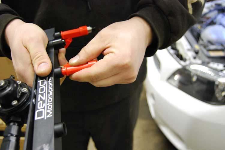
1 Thank you for purchasing the Dezod Motorsports Return Fuel System for your Scion tc. We took much pride in putting together a fuel system that would deliver a maximum amount of fuel as simply as possible with keeping value and ease of installation in mind. Enclosed in this installation manual you will find a comprehensive step by step set of instructions that shows you exactly what to do when performing an install with this kit. Ease of installation with minimal hassle was our goal when designing the system. We hope that this is helpful and that we have succeeded in helping you meet your fuel system needs. Included Parts: 1. Fuel rail and regulator assembly (shipped assembled), Modified Fuel Sending Unit, Aeromotive 100 Micron Fuel Filter, 152 Return line from regulator to tank, 72 Feed line from tank to filter, 65 feed line from filter to rail
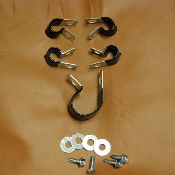
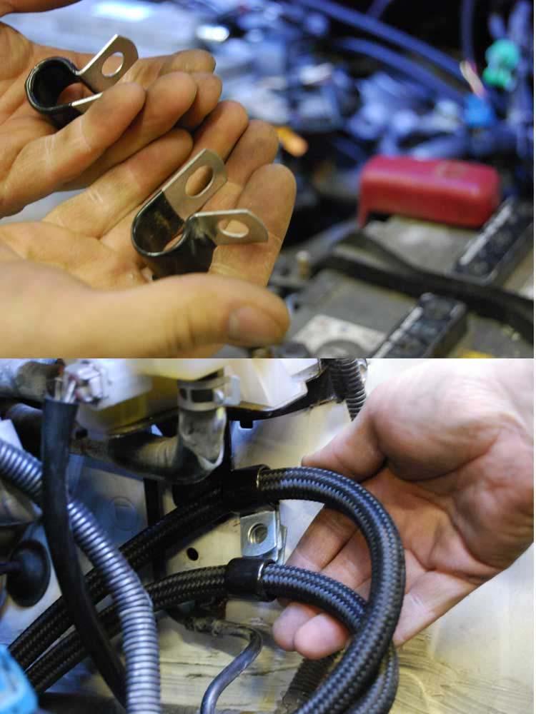
 ½ clamp for the fuel lines (3) self taping screws for mounting of the clamps (1) 6mm x 1.")
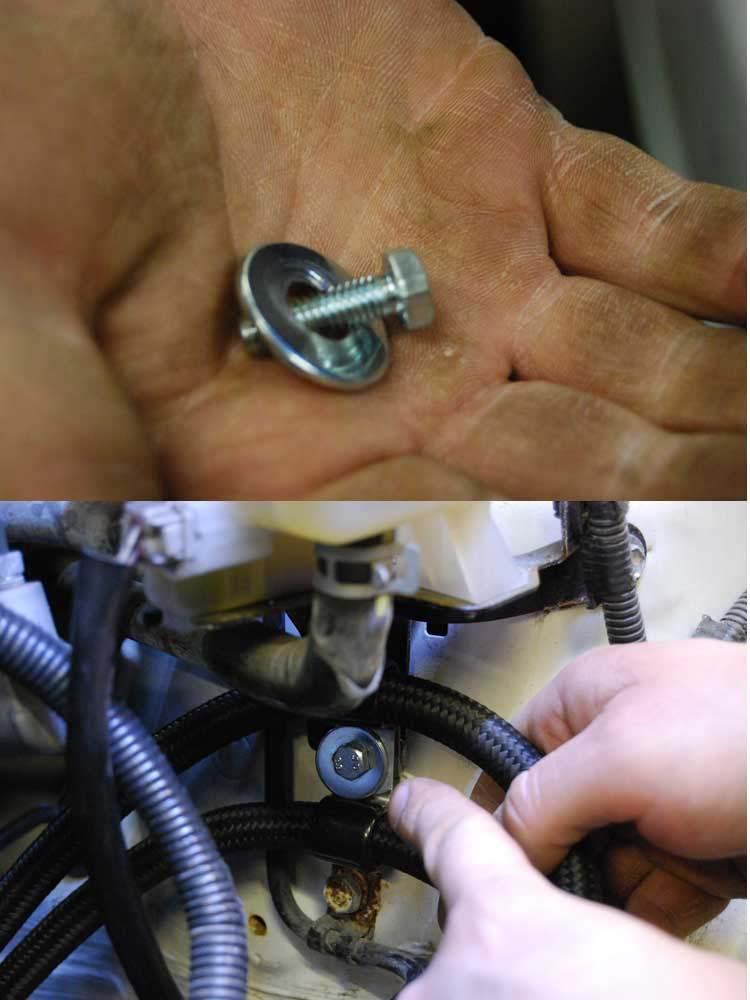
2 2. Installation hardware: (1) 1.25 clamp for the fuel filter (4) ½ clamp for the fuel lines (3) self taping screws for mounting of the clamps (1) 6mm x 1.0 bolt for mounting of clamps under hood (4) 5/16 washers for use with the self taping screws and bolt.
3
4 Tools needed (approximately): I have made a list of what you need if you were to follow this exactly. 1. 3/8 drive ratchet 2. 12mm 3/8 drive deep well socket 3. 14mm 3/8 drive socket 4. 3/8 drive extension 5. 8mm ¼ socket 6. ¼ ratchet 7. ¼ drive extension 8. large flat blade screwdriver 9. 10mm combination wrench 10. 3/32 hex key 11. 3/8 combination wrench 12. 3/8 ¼ drive socket 13. ¼ drive drill adapter 14. small flat blade screwdriver 15. cut off wheel or dremel with cut off wheel attachment. 16. pliers of some sort (I used long needle nose for most) 17. tape 18. loc-tite thread adhesive an aluminum wrench or adjustable wrench 20. black sharpie 21. Drill, cordless makes life easier 22. Shop towels or rags. 23. Jack 24. Jack stands Pre-cautions: 1. You are dealing with gasoline and it is flammable as you know. Disconnect the battery before performing any service regarding fuel. 2. NO SMOKING during this procedure. 3. When removing fuel related components it is important to de-pressurize the fuel system before servicing. There is no fuel test port to depressurize with this setup, so the best way to do so is to disconnect the large connector that powers the fuel pump, and start the car and let it run until it stalls. Then crank the engine times to make sure all the pressure is released. 4. Even after fuel pressure is released there will still be residual fuel left in the lines due to their construction. Make sure to use rags to catch any fuel that is spilled and make sure to dispose of those rags in the proper manner as they can catch fire and cause damage/and or death.
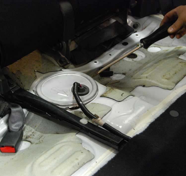
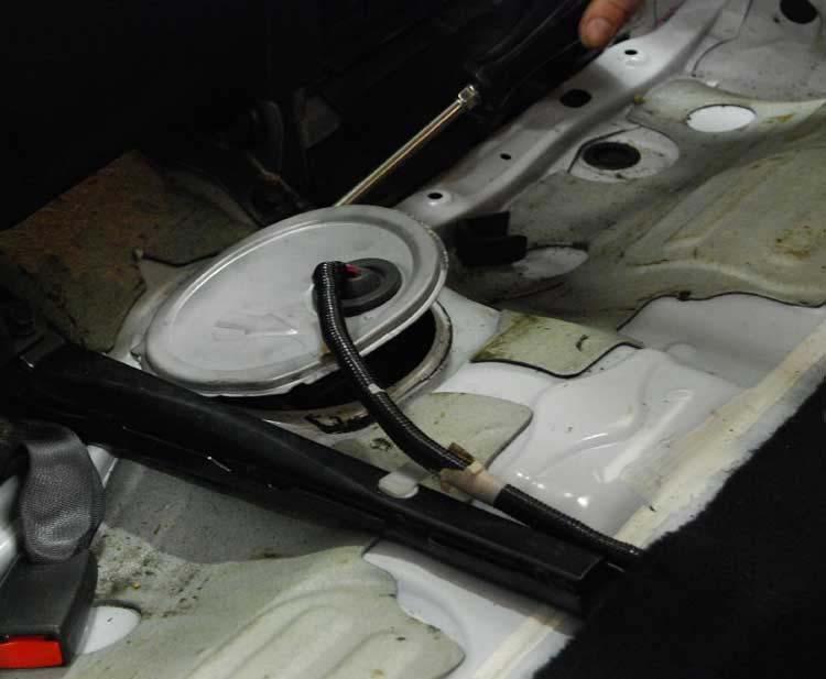
5 5. You will be cutting the sending unit cover, use eye protection for any part of this procedure. 6. General common sense will aid you in the install of this product. 7. THE MOST HELPFUL HINT I CAN OFFER IS TO RUN THE TANK TO NEAR EMPTY BEFORE DOING THIS INSTALL. IT WILL MAKE YOUR LIFE MUCH EASIER. Procedure: 1. Disconnect the battery negative terminal. 2. Remove the back seat 3. Here you can see the fuel pump sending unit cover. 4. Use a large flat blade screwdriver to gently pry this cover up. It is held down with strip caulk so it will pull up
6
7


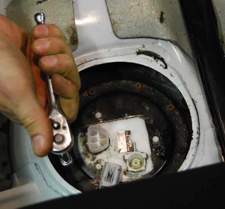
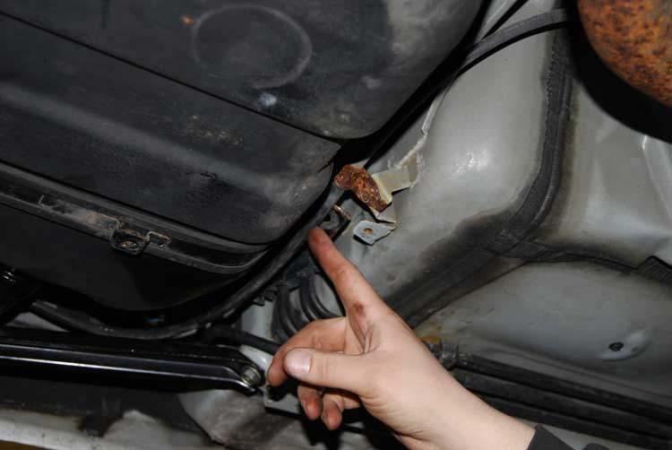
8 5. Next disconnect the two connectors seen here. The large one is for the fuel pump and float. 6. Here you see the sending unit. Note that the sending unit hold down has already been modified. This is the only thing you need to modify when installing this fuel system. It takes about 5 minutes and if you put the car back to stock you can still reuse this so no fear there. The black line with the yellow clip attached to it is the stock fuel feed line.


9 7. Use a small flat blade screwdriver to remove the yellow clip holding the fuel line in place. At this time you should have already de-pressurized the fuel system.


10 8. Using a shop rag to cover the fuel line, gently pull up on the line and move it to the side. Use a shop rag to soak up any residual fuel and dispose of properly.

11 9. Using a ¼ ratchet, extension and 8mm socket remove the bolts retaining the sending unit hold down. When you remove the connector that is on the bracket there is one bolt underneath it that needs to be removed as well. a. Important: before removing the hold down use a rag or shop air to remove debris from this area to keep any from getting into the fuel tank.
12


13 10. Once the bolts are removed and the area has been cleaned remove the sending unit hold down.

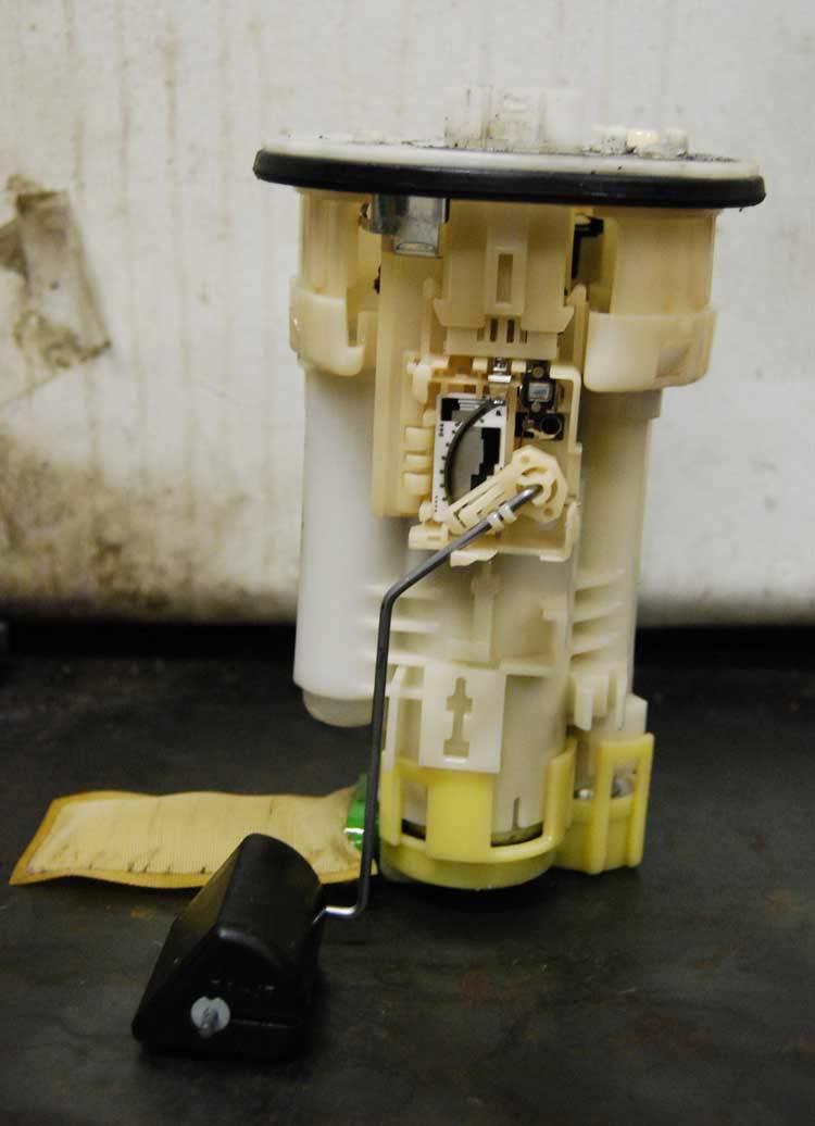
14 11. Remove the sending unit, hold it in place and allow excess fuel to drain. The float has a tendency to get stuck on the way out make sure not to rip up on it. Hold a rag under the sending unit to keep fuel from getting on the interior upholstery.


15 12. Here is a shot of the stock sending unit next to the modified unit. We ship our sending unit with the float that came with it. At this time you may chose to use

16 yours or just install the unit with ours. That is up to you. Just know that we have provided one for you.
17

18 13. This is the sending unit hold down. We only had one, and we already modified it when we built the prototype for this fuel system. All you need to do is modify yours to match ours. You re going to remove what looks like a triangle shape out of the hold down. You will make two cuts. The short cut is 1.5 approximately and the long cut is approximately Test fit it on the sending unit to make sure it clears the nylon washers. Modify until it does. Spray it with a quick blast of black spray paint to prevent any rust from forming.

19 14. Install your new sending unit. We are using our prototype for mock up purposes. Make sure you install your rubber gasket from your stock sending unit. This is important and needs to be in there.

20 15. Note that the orientation on the production pieces will be different than this. However for this pictures purpose we show you the two dowels that stick up from the sending unit. These are still used to properly locate the sending unit and bolt it in its correct orientation.

21 16. Place the modified sending unit hold down in place on its dowels. Using your ¼ ratchet tighten the bolts down starting at the one that goes under the connector on the bracket. Tighten them down in a cris-cross manner. Do not over tighten the bolts as they will strip or snap. Torque spec is 53 in/lbs.

22 17. Here is the finished product for now. Next we move to under the hood.

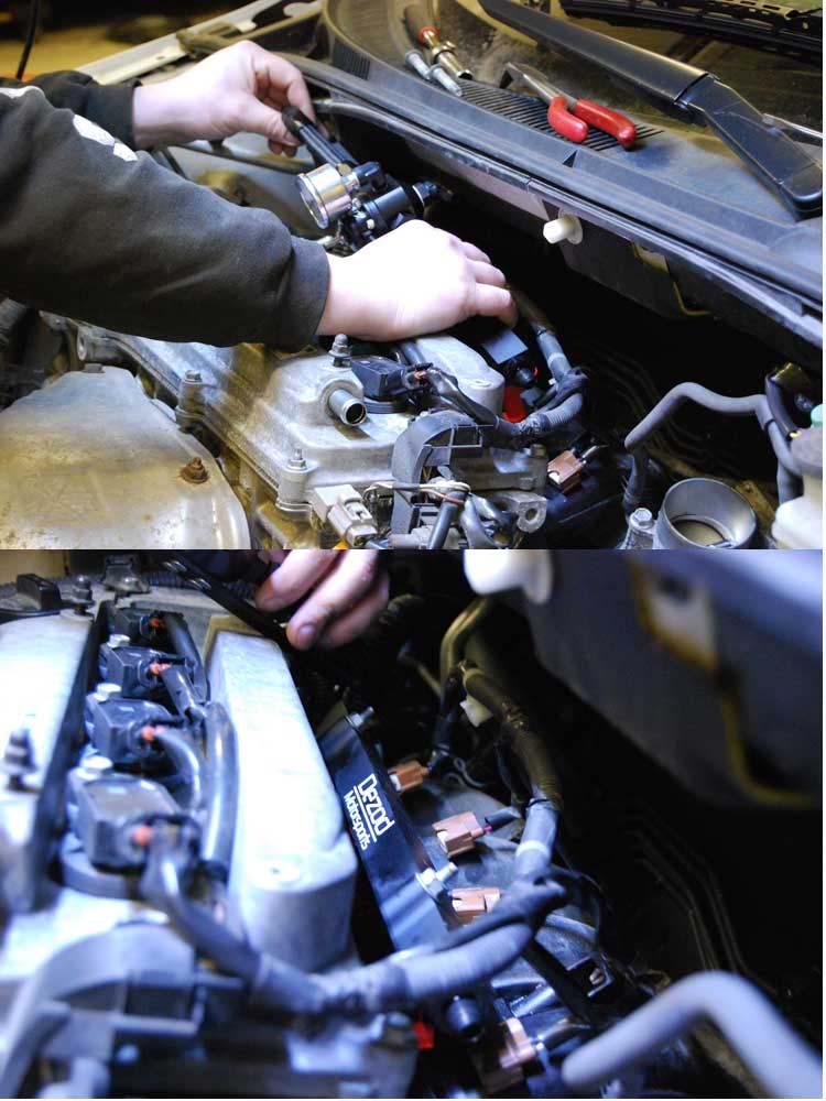
23 18. Under the hood we first start by removing your stock air box or intercooler pipe depending if you are NA or Turbo. Once you have done this remove the wiring harness from the fuel rail hold down bolts.

24 19. Using a pair of pliers, squeeze the clamp on the PCV hose, disconnect it form the valve and move it aside.

25 20. Disconnect the electrical connectors from your fuel injectors.


26 21. What you see here is a safety clamp for the fuel feed hose to the rail. Using a small flat blade screwdriver pry this off. 22. Using a rag to catch the residual fuel, disconnect the fuel hose and remove it. There is a yellow quick disconnect you need to push to dislodge the fuel line.

27 23. Use a 3/8 drive ratchet and a 12mm deep well socket and remove the two bolts holding the fuel rail in place.

28 24. Pull up on the fuel rail to dislodge the injectors from their lower seals. Caution these may come out with the injectors or they may just pop out and fall onto the intake manifold. Either way pay attention as you will need these when re-installing injectors. Also remove the stock fuel rail spacers. We have

29 supplied spacers to go with our fuel rail and these will take the place of the stock ones. When removing the rail it will come out with the pulse damper and fuel hose attached. Let the fuel drain and store it aside with your other removed stock parts for use if and when returning to stock.

30 25. Here is the new rail and regulator assembly. We assemble it so that the orientation is exactly how we intended it to be. Please do not alter this. The space is tight on this head and we have assembled this in house to assure that there is no physical interferences when installing this product. As you can see the delrin spacers are attached to this rail. We recommend installing them on the rail and then installing it in the head.

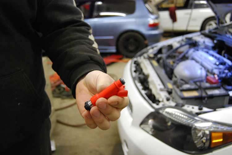
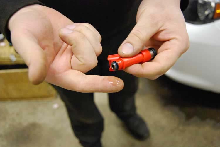
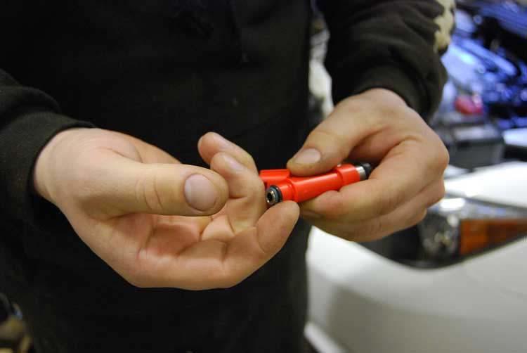
31 26. Take your injectors (850cc injector shown here, not included, sold separately) using a dab of clean engine oil on your finger lube the injector upper O-rings. Install the lubed injectors into the rail with a twisting motion. Doing this prevents tearing an O-ring. The injector bosses are radius to prevent this but better safe than sorry. ;)
32
33


34 27. Don t forget to make sure that the lower injector seals are in the head. Put them in the head first before installing the injectors. Lubing the lower section of the injector can aid in installation but use a very small amount if you do. 28. Install the fuel rail as shown. Make sure that the injectors are started and use hand pressure to seat them in their lower seals. Let the regulator hang to one side and install both the bolts. Tighten the bolts to 15ft/lbs maximum. If you are not using a torque wrench then tighten to snug and a ¼ to ½ turn. The main thing here is that the injectors are retained, snug, the injectors can rotate slightly and the spacers aren t split in half :P
35


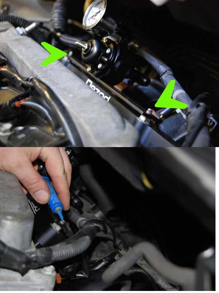
36 29. Install the regulator on the studs of the fuel rail bolts. Add a dab of loc-tite to the studs and install the 6mm x 1.0 nuts we supply.
37

38 30. Oh look, it s installed.

.")
39 31. Re-install the PCV hose. 32. Jack the car up on 4 jack stands for the easiest method of doing this next phase (if you have access to a lift that would make life easier). Using a 14mm socket remove the spring bolts from the rear section of the exhaust. Let exhaust hang.


40 33. Using a 10mm socket remove the bolts holding the exhaust shield to the chassis. Remove the shield.

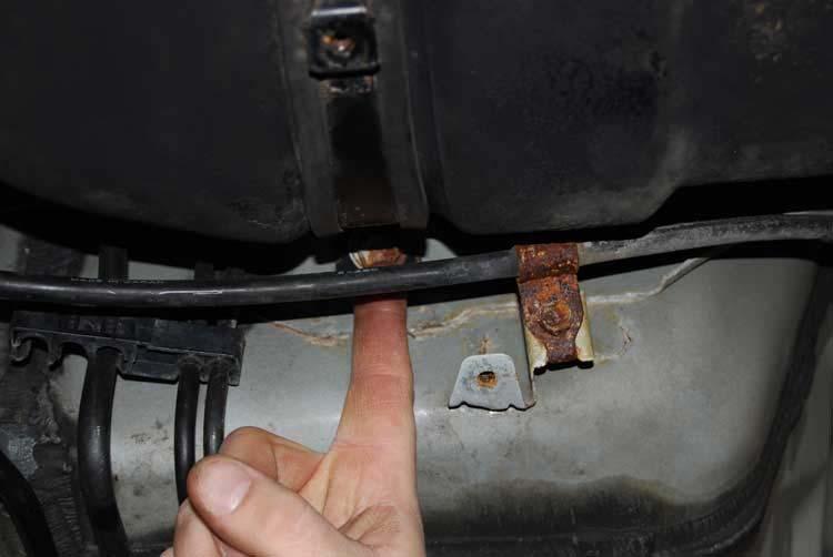
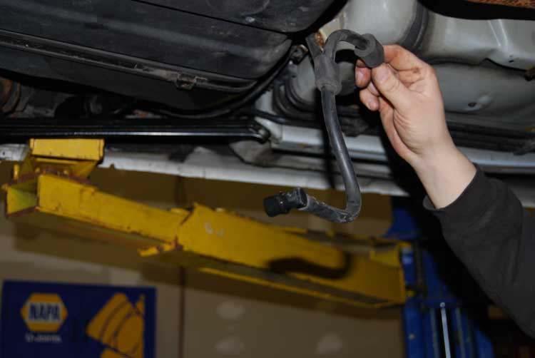
41 34. Using a 14mm remove this brace. It is located on the right side of the fuel tank. This supports the vapor canister and needs to be removed to facilitate lowering the fuel tank. 35. Using a small flat blade screwdriver un-clip the fuel feed hose from the tank to the main fuel line. Disconnect the line and use a rag to soak up residual fuel. Disconnect the line from its plastic guide on the fuel tank. (Let hang for the time being.)


42 36. These are the bolts to the fuel tank straps. Use a 14mm socket to remove them. If the tank is near empty like recommended in the precautions section of this manual

43 then the tank will not be a problem. Remove the bolts, lower the straps and let them hang slightly on the emergency brake cables. This will support the tank and will allow you to reach up to remove the stock fuel feed hose. Save this hose with the rest of your OEM parts for use later if you want to convert back to stock.
44
45

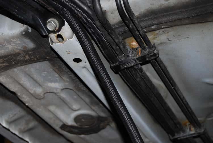
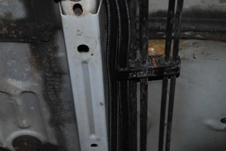
46 37. Pry down the plastic retainers that support the fuel and brake lines from the underside of the floor boards. I like to take advantage of what the factory has supplied as much as possible when it comes to routing hoses. So we are going to use the factory retainers to hold our return line for us. Move the factory feed line one space the right in the retainers. This will allow for a spare spot that we will run our return line.

47 38. Tape up the ends of the lines to prevent debris from getting inside when routing them through tight areas.

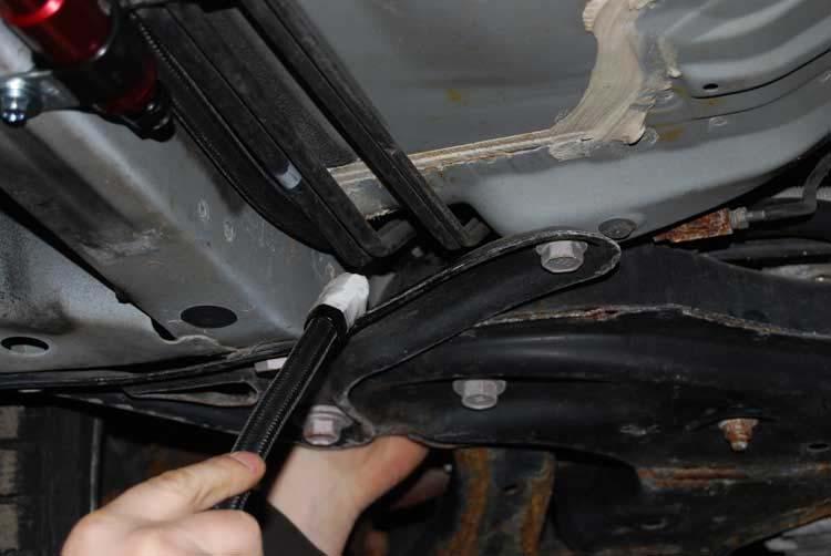
48 39. Route the return line through this area in the tank. Use this area and this area only. The body is very tight to the tank and if you use a different route you run the risk of pinching a fuel line. This is the area where the stock fuel feed hose routed.

49 40. Remove the tape from your hose; install it on the return side fitting. The return side fitting is the one that is closest to the passenger side.


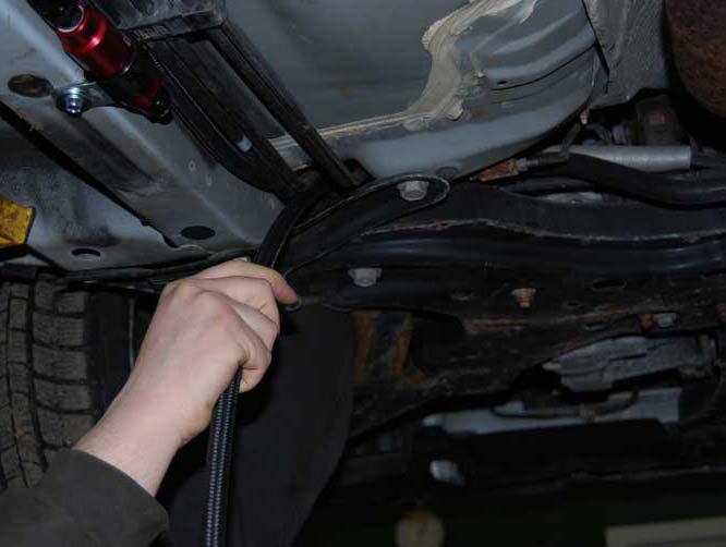
50 41. Route your return hose following the path that the stock fuel feed hose took. Push the hose into the clip where the stock fuel feed hose resided. Swoop it down near

51 the floor following the route of the factory line and install it in the space we made by moving the lines over in the fuel line retainers. You want the most slack back here near the fuel tank. Remember: Nice smooth radius bends.


52 42. Route the fuel hose through the retainers and push it into each retainer. Push the retainers back up onto the underside of the floor boards. With tape on the end of

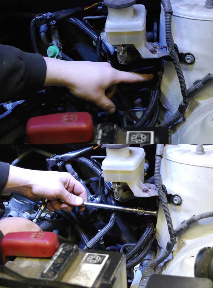
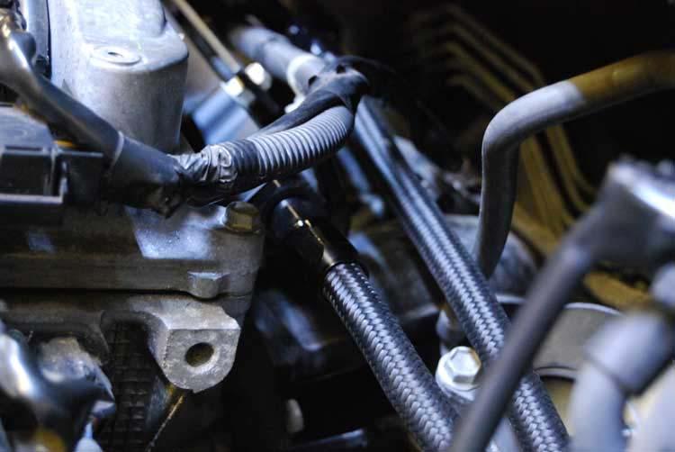
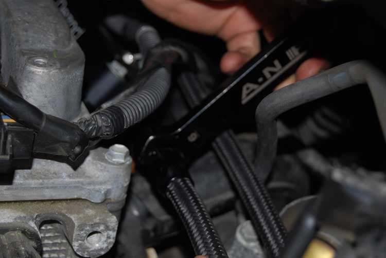
53 the hose route the other end of the return line up through the front subframe following the stock lines. You will run your line under the stock lines. 43. Route your return fuel line close to the drivers side of the engine bay. Install the line on the regulator outlet and tighten using a -6an wrench or adjustable wrench.
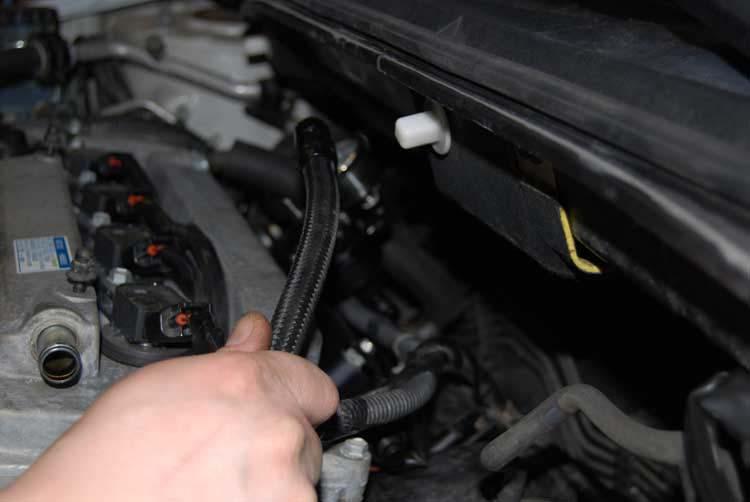
54

55 44. At the back of the car again. Tape the ends of the line that is going to go from the tank to the filter. Route the line up to the sending unit following the return line and the factory routing. You can use zip ties if you want to try to keep them together. I did not find it necessary.

56 45. Remove the tape, connect your line to the sending unit feed port. The feed port is the one closest to the drivers side. Here you se the orientation is different than in the earlier pictures. We decided to change this because of the line we were using. The black racing hose lines are lighter than stainless braided (there is a stainless inner braid), however it does not like to hold a curve as much due to it being more flexible. So we pointed the feed port to allow for a more direct routing. Note: The lines still follow the factory path.

57 46. Route your feed line closely following the return line. It fits snug up on top of the retainers and is held in place by the bulk of the retainer until you get to the filter where you will be installing clamps.
58

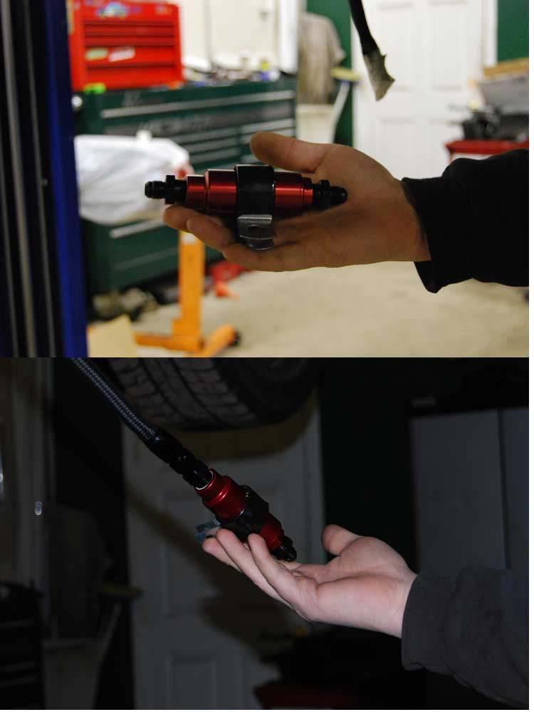
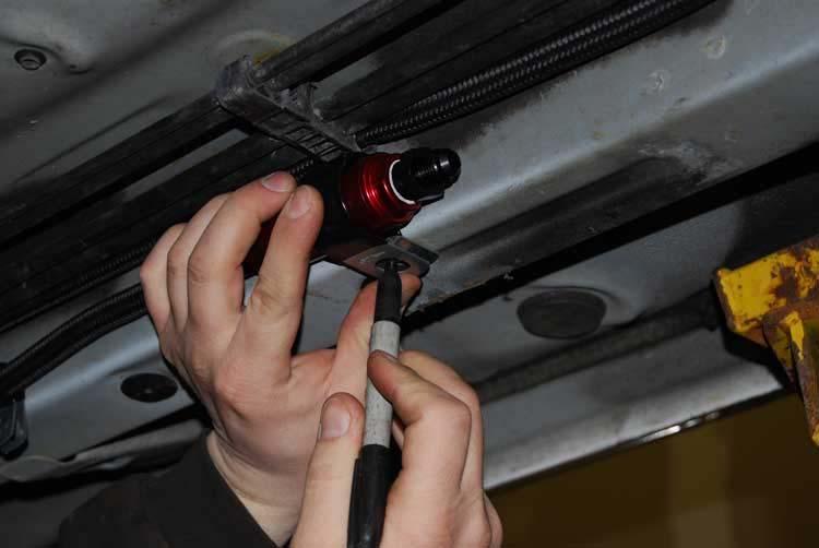
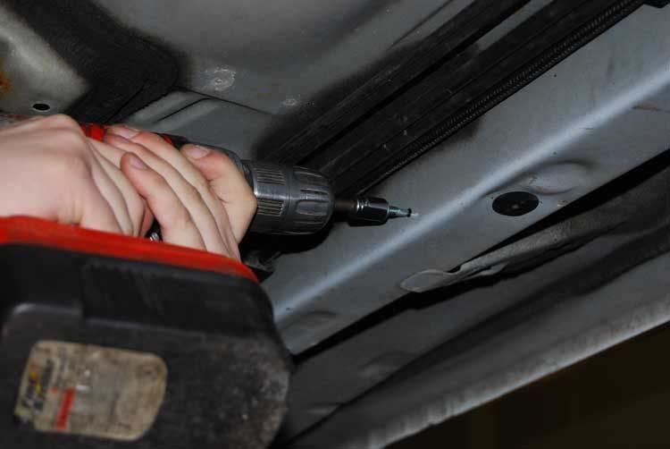
59 47. Here we have the filter we are using. Install the clamp on it, remove the tape from the ends of the fittings and loosely install the line on the fitting. Hold the filter up and mark where you want the hole to be when you mount the filter. Use the self taping screw to drill and tap a hole. Do the same for the lines before the filter. You will install two clamps pre filter. You will not be installing any clamps after the filter under the car as it is not necessary. The next clamps will be under hood. Install the filter in place. The filter has an arrow on it labeling the direction of flow. (take note to that direction and install it the proper way)
60
61
62

63 48. Route the hose from the filter to the rail up through the front sub frame following the return line we previously routed.
64

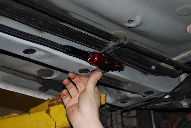
65 49. Remove the tape and connect the line to the filter. Tighten both fittings on the filter using a -6an wrench or adjustable wrench.

66 50. Use a 10mm socket and extension to remove the 6mm x 1.0 bolt from the shock tower. Use the clamps supplied and arrange them on the lines as shown. Interlocking both clamps so that the clamp haves layer on each other. Install the 6mmx 1.0 bolt and 5/16 washer we supplied in the kit to bolt these to the shock tower.
67
68
69


70 51. Remove the tape from the fitting and connect the line to the feed port on the rail. Tighten using a -6an wrench or adjustable wrench.
71

72 52. Connect a manifold vacuum source to the regulator, and use a zip tie to secure the line. Set your fuel pressure by adjusting the center bolt on the regulator with a 3/32 hex key. Once the desired fuel pressure is set lock down the nut using a 3/8 combination wrench.

73 53. Connect the connectors for the sending unit and the emissions sensors.

74 54. Prime the fuel system and check for leaks. If no leaks are found press the cover down and reinstall your back seat. Start the engine and set the fuel pressure to 43.5 psi. This is the standard pressure that all fuel injectors are tested to. This is

75 the base fuel pressure you will be running. Adjust to your specific needs accordingly if you desire a higher or lower base. Important note! The float is a card resistor which is very sensitive so the ECU buffers the signal to keep the gauge from bouncing around. What does this mean? It means that when you first start the car it will take a minute or two for the level on the gauge to return to normal so don t panic. If it does not come back after 15 minutes then the float is faulty and you should install yours from your stock sending unit. 55. Once you have the car started, fuel pressure dialed in and you are certain there are no leaks go ahead and reinstall the gas tank straps, bracket that supports the vapor canister, exhaust shield and exhaust section. Congratulations on completing your fuel system install we hope it was a simple endeavor. Drive safely.
IAG Air / Oil Separator (AOS) For STi
 For STi") IAG Air / Oil Separator (AOS) For 2008-14 STi Part# IAG-ENG-7000 Tools Required: Ratchet, torque wrench, extensions, needle nose pliers, hose cutter, snips/scissors Sockets: 10mm, 12mm 13mm Wrenches: 10mm,
IAG Air / Oil Separator (AOS) For 2008-14 STi Part# IAG-ENG-7000 Tools Required: Ratchet, torque wrench, extensions, needle nose pliers, hose cutter, snips/scissors Sockets: 10mm, 12mm 13mm Wrenches: 10mm,
IAG Street Series Air / Oil Separator (AOS) For 2017 WRX
 For 2017 WRX") P IAG Street Series Air / Oil Separator (AOS) For 2017 WRX Part# IAG-ENG-7152 Tools Required: Ratchet, torque wrench, extensions, needle nose pliers, hose cutter, snips/scissors, flathead screwdriver,
P IAG Street Series Air / Oil Separator (AOS) For 2017 WRX Part# IAG-ENG-7152 Tools Required: Ratchet, torque wrench, extensions, needle nose pliers, hose cutter, snips/scissors, flathead screwdriver,
Slingshot Rotrex Supercharger Kit
 Slingshot Rotrex Supercharger Kit This supercharger kit improves on the Slingshot by forcing more dense air into the engine and creating more power. Installation time of the supercharger depends on you
Wrenches: ⅞, 8mm, 10mm, 13mm, 19mm P. allen, Other: Electrical Tape
 IAG Street Series Air / Oil Separator (AOS) For 2008-14 STI Part# IAG-ENG-7100 Tools Required: Ratchet, torque wrench, extensions, needle nose pliers, hose cutter, snips/scissors, flat head screw driver,
Procharger Stage II Intercooled Supercharger System (11-14 GT)
") Procharger Stage II Intercooled Supercharger System (11-14 GT) Installation Time: Approximately one day. Installed on 2012 Mustang GT 5.0/Manual Required Tools 3/8 Socket Set (Standard and Metric) 1/2
Procharger Stage II Intercooled Supercharger System (11-14 GT) Installation Time: Approximately one day. Installed on 2012 Mustang GT 5.0/Manual Required Tools 3/8 Socket Set (Standard and Metric) 1/2
IAG Street Series Air / Oil Separator (AOS) For WRX & WRX STI
 For WRX & WRX STI") IAG Street Series Air / Oil Separator (AOS) For 2006-07 WRX & 2004-07 WRX STI Part# IAG-ENG-7100 Tools Required: Ratchet, torque wrench, extensions, needle nose pliers, hose cutter, snips/scissors, flat
IAG Street Series Air / Oil Separator (AOS) For 2006-07 WRX & 2004-07 WRX STI Part# IAG-ENG-7100 Tools Required: Ratchet, torque wrench, extensions, needle nose pliers, hose cutter, snips/scissors, flat
IAG Street Series Air / Oil Separator (AOS) For WRX
 For WRX") P IAG Street Series Air / Oil Separator (AOS) For 2015-16 WRX Part# IAG-ENG-7152 Tools Required: Ratchet, torque wrench, extensions, needle nose pliers, hose cutter, snips/scissors, flat head screw driver,
P IAG Street Series Air / Oil Separator (AOS) For 2015-16 WRX Part# IAG-ENG-7152 Tools Required: Ratchet, torque wrench, extensions, needle nose pliers, hose cutter, snips/scissors, flat head screw driver,
8 Zip Tie Zip Tie 1 Union Fitting 1 ½ ½ Union Reducer Fitting Union 1 5/8 ½ (For Plastic Intake Manifold Vehicles)
") P IAG Street Series Air / Oil Separator (AOS) For 2017 STI Part# IAG-ENG-7151 Tools Required: Ratchet, torque wrench, extensions, needle nose pliers, hose cutter, snips/scissors, flat head screw driver,
P IAG Street Series Air / Oil Separator (AOS) For 2017 STI Part# IAG-ENG-7151 Tools Required: Ratchet, torque wrench, extensions, needle nose pliers, hose cutter, snips/scissors, flat head screw driver,
INSTALLATION INSTRUCTIONS Dual Catch Can Kit Subaru Turbo and STi Document# Support:
 INSTALLATION INSTRUCTIONS Dual Catch Can Kit 02-14 Subaru Turbo and 2015+ STi Document# 19-0099 Support: info@radiumauto.com This document covers the installation of a Radium dual catch can kit for the
IAG Street Series Air / Oil Separator (AOS) For WRX & WRX STI
 For WRX & WRX STI") IAG Street Series Air / Oil Separator (AOS) For 2006-07 WRX & 2004-07 WRX STI Part# IAG-ENG-7150 Tools Required: Ratchet, torque wrench, extensions, needle nose pliers, hose cutter, snips/scissors, flat
IAG Street Series Air / Oil Separator (AOS) For 2006-07 WRX & 2004-07 WRX STI Part# IAG-ENG-7150 Tools Required: Ratchet, torque wrench, extensions, needle nose pliers, hose cutter, snips/scissors, flat
IAG Competition Series Air / Oil Separator (AOS) For 2017 STI
 For 2017 STI") P IAG Competition Series Air / Oil Separator (AOS) For 2017 STI Part# IAG-ENG-7251 Tools Required: Ratchet, torque wrench, extensions, needle nose pliers, hose cutter, snips/scissors, flat head screw driver,
P IAG Competition Series Air / Oil Separator (AOS) For 2017 STI Part# IAG-ENG-7251 Tools Required: Ratchet, torque wrench, extensions, needle nose pliers, hose cutter, snips/scissors, flat head screw driver,
IAG Street Series Air / Oil Separator (AOS) For WRX & WRX STI
 For WRX & WRX STI") IAG Street Series Air / Oil Separator (AOS) For 2006-07 WRX & 2004-07 WRX STI Part# IAG-ENG-7150 Tools Required: Ratchet, torque wrench, extensions, needle nose pliers, hose cutter, snips/scissors, flat
IAG Street Series Air / Oil Separator (AOS) For 2006-07 WRX & 2004-07 WRX STI Part# IAG-ENG-7150 Tools Required: Ratchet, torque wrench, extensions, needle nose pliers, hose cutter, snips/scissors, flat
IAG Competition Series Air / Oil Separator (AOS) For WRX
 For WRX") P IAG Competition Series Air / Oil Separator (AOS) For 2015-16 WRX Part# IAG-ENG-7252 Tools Required: Ratchet, torque wrench, extensions, needle nose pliers, hose cutter, snips/scissors, flat head screw
P IAG Competition Series Air / Oil Separator (AOS) For 2015-16 WRX Part# IAG-ENG-7252 Tools Required: Ratchet, torque wrench, extensions, needle nose pliers, hose cutter, snips/scissors, flat head screw
#TL T EA888 GEN 3 FUELING SYSTEM/ INSTALLATION INSTRUCTIONS
 #TL100069 2.0T EA888 GEN 3 FUELING SYSTEM/ INSTALLATION INSTRUCTIONS Notes: These instructions were written for a North American specification MkVII GTI. Other models, like the Golf R, are similar. When
Ford Racing Performance Improvement Intake Manifold (96-04 GT) Time Necessary: Approximately 4 hours
 Time Necessary: Approximately 4 hours") Ford Racing Performance Improvement Intake Manifold (96-04 GT) Time Necessary: Approximately 4 hours Tools Required: Ratchet and socket set Torque wrench Large adjustable wrench Needle nose pliers A dozen
Ford Racing Performance Improvement Intake Manifold (96-04 GT) Time Necessary: Approximately 4 hours Tools Required: Ratchet and socket set Torque wrench Large adjustable wrench Needle nose pliers A dozen
These instructions were written for reference only and the use of a factory service manual is recommended.
 Introducing the CorkSport High Pressure Fuel Line designed for the MZR DISI. This fuel line is designed to replace the OEM fuel line which are prone to failure at the brazed connection at the rail. The
2017+ L5P Duramax 3 ½ Down Pipe & EGR Fix Kit
 2017+ L5P Duramax 3 ½ Down Pipe & EGR Fix Kit Covers installation of PN s: WCF100630, WCF100829 Note: This Kit is for off road competition use only! Off Road Competition Use Tuning & Exhaust System is
Parts List See cover Page
 Thank you for purchasing the CorkSport Front Mount Intercooler Kit for the 2010-2013 Mazdaspeed 3. Keep your BAT s under check with the CorkSport FMIC Kit with the small or large intercooler. Please let
These instructions were written for reference only and the use of a factory service manual is recommended.
 Introducing the CorkSport High Pressure Fuel Line designed for the MZR DISI. This fuel line is designed to replace the OEM fuel line which are prone to failure at the brazed connection at the rail. The
IAG Street Series Air / Oil Separator (AOS) For WRX
 For WRX") IAG Street Series Air / Oil Separator (AOS) For 2008-14 WRX Part# IAG-ENG-7100 Tools Required: Ratchet, extensions, needle nose pliers, hose cutter, snips/scissors, flat head screw driver, hose clamping
IAG Street Series Air / Oil Separator (AOS) For 2008-14 WRX Part# IAG-ENG-7100 Tools Required: Ratchet, extensions, needle nose pliers, hose cutter, snips/scissors, flat head screw driver, hose clamping
08-18 STI Flex Fuel Bluetooth Mk2 Kit Install Instructions For Cobb Tuning Access Port
 For Cobb Tuning Access Port Delicious Tuning 1948 Don Lee Place Suite #7 Escondido, CA 92029 408-480-0995 Rough Draft BJP Rev: 2.0 Date: 2/1/17 FFBT parts: (1) Ethanol Content Analyzer Module (1) Ethanol
3 October 2016 PN# V Dodge Twin Turbo Kit (I-00274) ½ D o d g e 2 4 v I S B
 ½ D o d g e 2 4 v I S B") 3 October 2016 PN#1045320 24V Dodge Twin Turbo Kit (I-00274) 1 DOWNLOAD ENHANCED INSTALL MANUALS AT dieselperformance.com BD Twin Turbo Kit 1998½- 2 0 0 2 D o d g e 2 4 v I S B Part# 1045320 PLEASE READ
3 October 2016 PN#1045320 24V Dodge Twin Turbo Kit (I-00274) 1 DOWNLOAD ENHANCED INSTALL MANUALS AT dieselperformance.com BD Twin Turbo Kit 1998½- 2 0 0 2 D o d g e 2 4 v I S B Part# 1045320 PLEASE READ
05-08 GT. Hellion Power Systems Mustang Kit Instructions
 Hellion Power Systems 05-08 Mustang Kit Instructions 1. Disconnect Battery 2. Drain Radiator, keep fluid for re-installation. 3. Remove air box and inlethoses. 6. Next, underneath, punch oil pan for turbo
Z1 Motorsports 370Z/G37 Oil Cooler Kit Installation Manual
 Z1 Motorsports 2877 Carrollton Villa Rica Hwy Carrollton GA 30116 770.838.7777 Z1 Motorsports 370Z/G37 Oil Cooler Kit Installation Manual For 19, 25 and 34 Row Oil Cooler Kits Parts Included: 1 SETRAB
RHINO SUSPENSION SYSTEM INSTALLATION INSTRUCTIONS
 PARTS INCLUDED: 2 FRONT UPPER A-ARMS 2 FRONT LOWER A-ARMS 2 UNI-BALL JOINTS 2 UNI-BALL JOINT STUDS 2 UNI-BALL JOINT CAPS 2 RETAINING RINGS 1 FRONT SHOCK ASSEM. 2 DELRON STEERING STOPS 2 SHOCK MOUNT SPACERS
List of parts needed below. Tools needed
 1 BMW 645 Coolant leak repair (Cap with Seal Repair and Expanding Coolant Pipe Installation w Pics) By Michael R. Brown (Estimated time to complete the job is 6-8 hrs) List of parts needed below. BMW PART
MAZDASPEED3 Intercooler Instructions
 MAZDASPEED3 Intercooler Instructions Congratulations on your purchase of the COBB Tuning Front Mount Intercooler System for your 2007-2009 Mazdaspeed3. The following instructions should assist you through
BEFORE BEGINNING INSTALLATION
 COMPLETE CHASSIS FUEL LINE KITS For 1996-2000 Honda Civic Equipped with B-Series Engine INSTALLATION INSTRUCTIONS PLEASE study these instructions carefully before beginning this installation. Most installations
SLP Camaro ZL1 STAGE 3 (650 HP)
") SLP - 2012 Camaro ZL1 STAGE 3 (650 HP) PART #26002 PACKING LIST Before installation, use this check list to make sure all necessary parts have been included. ITEM QTY CHECK PART NUMBER DESCRIPTION 1. 1
SLP - 2012 Camaro ZL1 STAGE 3 (650 HP) PART #26002 PACKING LIST Before installation, use this check list to make sure all necessary parts have been included. ITEM QTY CHECK PART NUMBER DESCRIPTION 1. 1
SKID MARK GARAGE. Axillary Fuel Supply
 1 SKID MARK GARAGE Axillary Fuel Supply *Disclaimer: Our Axillary Fuel kits are designed to fit most late model GM vehicles with minimum modifications. While not quite a universal kit for all, it has been
Page1. ISF Stainless Steel Headers // Part# HDR-004
 Congratulations on the purchase of your ISF Stainless Steel Headers and thank you for choosing Sikky Manufacturing. This installation manual is intended to guide you through the removal of the factory
DrVanos.com Stage II Installation Instructions. Tool rental is available with the purchase of a vanos kit *See website for more info*
 DrVanos.com Stage II Installation Instructions Special Tools Needed: Camshaft locking tool TDC Crank pin Sprocket turning tool Tool rental is available with the purchase of a vanos kit *See website for
INSTALLATION INSTRUCTIONS
 INSTALLATION INSTRUCTIONS FUEL PUMP HANGER MITSUBISHI LANCER EVOLUTION X Support: info@radiumauto.com Document# 19-0116 WARNING: DO NOT EXPOSE WORK AREA TO ANY SPARKS OR FIRE. DO NOT SMOKE WHILE WORKING
Intake Manifold Spacers. For the Porsche 928
 The following photos and instructions are to install the 928 Motorsports, LLC. Intake Manifold Spacers For the 1987-1995 Porsche 928 Questions? Call our toll free number 877-FOR-928M or send an e-mail
Air Oil Separator for WRX
 Air Oil Separator for 2015+ WRX 2018-06-05 Thank you for purchasing this PERRIN product for your car! Installation of this product should only be performed by persons experienced with installation of aftermarket
The M7 Direct Flow Intercooler (DFIC) Installation Guide
 Installation Guide") The M7 Direct Flow Intercooler (DFIC) Installation Guide This information is meant only as a guide. The author of this information,, or any M7 Tuning employees assumes no liabilities for any outcomes resulting
The M7 Direct Flow Intercooler (DFIC) Installation Guide This information is meant only as a guide. The author of this information,, or any M7 Tuning employees assumes no liabilities for any outcomes resulting
FULL LENGTH HEADERS/ CATTED HEAD PIPES
 INSTALLATION INSTRUCTIONS INS232 2016-2018 CAMARO 6.2L V8 FULL LENGTH HEADERS/ CATTED HEAD PIPES Part #4044 and 40440 Special Tools required: 10mm, 12mm, 13mm, 15mm Socket and Wrenches, Pliers, Saw, Welder
Shotgun Single Barrel HPFP install guide
 Shotgun Single Barrel HPFP install guide Thank you for your purchase of the VTT Shotgun Single Barrel HPFP upgrade! First thing to do when you open your box is to make sure all parts are in their respective
BBK LONG TUBE HEADERS (99-04 GT, Mach 1, Bullitt)
") BBK LONG TUBE HEADERS (99-04 GT, Mach 1, Bullitt) Install Time: Approx. 8-10 hrs Parts Needed: BBK Long Tube Headers Shorty mid pipe X/H O2 wiring harness extensions Hi-temp thread locker Tools Required:
BBK LONG TUBE HEADERS (99-04 GT, Mach 1, Bullitt) Install Time: Approx. 8-10 hrs Parts Needed: BBK Long Tube Headers Shorty mid pipe X/H O2 wiring harness extensions Hi-temp thread locker Tools Required:
Chevy Sonic 1.4L Intake Manifold
 Chevy Sonic 1.4L Intake Manifold Install Time: 3 hours In the Box: (1) Racer X Intake manifold (6) M8x1.25 bolts (4) M6x1 bolts (2) 1/8 NPT plugs (1) 3/8 NPT plug (1) 1/4 NPT 90 degree barb (4) Small O-rings
INSTALLATION INSTRUCTIONS
 INSTALLATION INSTRUCTIONS FUEL SURGE TANK INSTALLATION KIT 1999-2006 BMW E46 COUPE Document# 19-0056 Support: info@radiumauto.com Note: This kit was designed for a standard single pump Radium Engineering
Subaru WRX Performance Charge-Pipe System, 2015+
 PARTS LIST AND PARTS LIST 1PC BAR-AND-PLATE INTERCOOLER 1PC INTERCOOLER MOUNTING BRACKET 1PC CHARGE-PIPE ASSEMBLY 1PC AIR DIVERTER WITH ATTACHED RUBBER GASKETS 1PC CHARGE-PIPE-TO-INTERCOOLER HOSE INSTALLATION
Instant Chat off the main page of Or simply call our tech team at
 Subaru WRX/STI Air Oil Separator for Front Mounted Intercooler Setups 2013-02- 22 Thank you for purchasing this PERRIN product for your car! Installation of this product should only be performed by persons
97-04 CHEVROLET CORVETTE C5
 97-04 CHEVROLET CORVETTE C5 IMPORTANT! WARRANTY AND INSTALLATION INSTRUCTIONS Please Forward All Information to Consumer Be sure to review the enclosed instructions prior to beginning the installation
What s in your new header system kit?
 !"#$% "#$%& ' "())' **+ Congratulations on your purchase of the Dynatech / SuperMaXX system for the Dodge Magnum / Chrysler 300C. We believe, and think you will agree that this system is second to none
Single Barrel Shotgun HPFP Install Guide
 Single Barrel Shotgun HPFP Install Guide Thank you for purchasing the VTT Single Barrel Shotgun HPFP upgrade kit! PLEASE READ THE ENTIRE GUIDE BEFORE BEGINNING INSTALLATION! The first thing you should
Low Range HD 2 Inch Body Lift Kit (Sidekick, GV, Vitara, Tracker, X90) SKU# KSP-BL2
 SKU# KSP-BL2") Low Range HD 2 Inch Body Lift Kit (Sidekick, GV, Vitara, Tracker, X90) SKU# KSP-BL2 Installation Instructions Background: These instructions are designed for installing the 2 body lift. They can also be
Low Range HD 2 Inch Body Lift Kit (Sidekick, GV, Vitara, Tracker, X90) SKU# KSP-BL2 Installation Instructions Background: These instructions are designed for installing the 2 body lift. They can also be
INSTALLATION INSTRUCTIONS BILLET FUEL RAIL KIT
 INSTALLATION INSTRUCTIONS BILLET FUEL RAIL KIT MITSUBISHI LANCER EVOLUTION X Document# 19-0067 Support: info@radiumauto.com WARNING: DON'T SMOKE OR WORK WITH OPEN SPARKS WHILE WORKING ON THE FUEL SYSTEM
INSTALL MANUAL D o d g e 1 2 v 6 B T A PLEASE READ ALL INSTRUCTIONS BEFORE INSTALLATION.
 PN#1045310 12V Dodge Twin Turbo Kit (I-00273) 1 INSTALL MANUAL BD Twin Turbo Kit 1994-1 9 9 8 D o d g e 1 2 v 6 B T A Part# 1045310 PLEASE READ ALL INSTRUCTIONS BEFORE INSTALLATION. * Picture as shown
All cores due 30 days after invoice date - no credit after 60 days.
 NO WARRANTY STATEMENT High performance parts & products no warranty policy: The purchaser understands and recognizes that high performance diesel products and services sold by INDUSTRIAL INJECTION SERVICE.
VRSC-DX Truck-Lite LED Headlight Installation Instructions
 VRSC-DX Truck-Lite LED Headlight Installation Instructions The following Instructions are for installing a 7 Truck-Lite LED headlight into a Harley Davidson VRSC-DX Night Rod Special fairing. Other 7 headlights
Z1 Motorsports 350Z / G35 Oil Cooler Kit Installation Manual
 Z1 Motorsports 2877 Carrollton Villa Rica Hwy Carrollton GA 30116 770.838.7777 Z1 Motorsports 350Z / G35 Oil Cooler Kit Installation Manual For 19, 25 and 34 Row Oil Cooler Kits Parts Included: 1 Aluminum
INSTALLATION INSTRUCTIONS
 INSTALLATION INSTRUCTIONS FUEL SURGE TANK INSTALLATION KIT 1999-2006 BMW E46 COUPE Document# 19-0056 Support: info@radiumauto.com Note: This kit wasn t designed for a FST-R, but can be accomplished. 1.
INSTALLATION INSTRUCTIONS FUEL SURGE TANK KIT
 INSTALLATION INSTRUCTIONS FUEL SURGE TANK KIT BMW E46 3-Series, Excl Convertible Document: 19-0056 Support: info@radiumauto.com Relieve fuel pressure in vehicle before beginingthe installation. Disconnect
Installation Instructions
 Suzuki Samurai 1 Inch and 2 Inch Body Lift Kit (SKU# SSP-BL) Installation Instructions Background: These instructions are designed for installing the 2 body lift. Our approach is to raise the entire body
LML 3 Y-Bridge Kit or High Flow Intake Bundle Package
 2011-2016 LML 3 Y-Bridge Kit or High Flow Intake Bundle Package Covers installation of PN s: WCF100607, WCF100691, WCF100716, & WCF100353 Note: This Kit is for off road competition use only! Overview-
WRX/STI Engine Oil Cooler
 2002-14 WRX/STI Engine Oil Cooler 2014-04-21 Thank you for purchasing this PERRIN product for your car! Installation of this product should only be performed by persons experienced with installation of
INSTALLATION INSTRUCTIONS
 INSTALLATION INSTRUCTIONS FST KIT FOR PORT INJECTION 2013+ FORD FOCUS ECOBOOST Document: 19-0168 Support: info@radiumauto.com Working under the vehicle is required. This installation is best performed
Instant Chat off the main page of Or simply call our tech team at
 02-07 WRX/STI Air Oil Separator for Top Mounted Intercooler Setups 2013-02- 27 Thank you for purchasing this PERRIN product for your car! Installation of this product should only be performed by persons
4. Remove (4) 10mm and (1) 7mm bolt that holds fascia at front corners, on each side
 10mm and (1) 7mm bolt that holds fascia at front corners, on each side") 2010 Camaro LS3 1. Disconnect battery ground 2. Remove front wheels 3. Remove (5) push pins and (5) #20 torx screws on inner front wheel well liners and remove liners on each side 4. Remove (4) 10mm and
2010 Camaro LS3 1. Disconnect battery ground 2. Remove front wheels 3. Remove (5) push pins and (5) #20 torx screws on inner front wheel well liners and remove liners on each side 4. Remove (4) 10mm and
TOP FEED FUEL RAIL KIT for WRX
 TOP FEED FUEL RAIL KIT for 2002-14 WRX Thank you for purchasing this PERRIN product for your car! Installation of this product should only be performed by persons experienced with installation of aftermarket
INSTALLATION INSTRUCTIONS FUEL RAIL
 INSTALLATION INSTRUCTIONS FUEL RAIL MITSUBISHI EVO X Document# 19-0067 Support: info@radiumauto.com WARNING: DON'T SMOKE OR WORK WITH OPEN SPARKS WHILE WORKING ON THE FUEL SYSTEM PREPARING THE VEHICLE:
INSTALLATION INSTRUCTIONS
 INSTALLATION INSTRUCTIONS Part# 22-7810 Add On Kit for Your ADS System Contents: Complete Install Kit for Your ARB CKMTA12V Compressor For the most up-to-date instructions please visit www.updownair.com
 Special Tools Needed: DrVanos.com Stage I Installation Instructions Camshaft locking tool TDC Crank pin Sprocket turning tool Tool rental is available with the purchase of a vanos kit *See website for
2015 Mustang Lightbar (All Models) CDC#
 CDC#") 2015 Mustang Lightbar (All Models) CDC# 1511-7000-01 Components: 1 CDC Lightbar Note: READ instructions before starting installation!!! CDC Part# Driver side bracket 0511-6001-05 Passenger side bracket
2015 Mustang Lightbar (All Models) CDC# 1511-7000-01 Components: 1 CDC Lightbar Note: READ instructions before starting installation!!! CDC Part# Driver side bracket 0511-6001-05 Passenger side bracket
Installation Instructions for Chevrolet C5 Corvette Lingenfelter High Flow Fuel Pump Module
 Installation Instructions for 1997-2003 Chevrolet C5 Corvette Lingenfelter High Flow Fuel Pump Module PN: L710650197 Lingenfelter Performance Engineering 1557 Winchester Road Decatur, IN 46733 (260) 724-2552
INSTALLATION INSTRUCTIONS AOS-R (Air Oil Separator-Return) Turbo Subaru and STi Document# Support:
 Turbo Subaru and STi Document# Support:") INSTALLATION INSTRUCTIONS AOS-R (Air Oil Separator-Return) 02-14 Turbo Subaru and 2015+ STi Document# 19-0102 Support: info@radiumauto.com These instructions are based on a vehicle with an OEM turbocharger
INSTALLATION INSTRUCTIONS AOS-R (Air Oil Separator-Return) 02-14 Turbo Subaru and 2015+ STi Document# 19-0102 Support: info@radiumauto.com These instructions are based on a vehicle with an OEM turbocharger
Performance Inlet Manifold
 Performance Inlet Manifold Tools needed (some tools not required on some models): 13mm Combination Wrench Flat Blade Screwdriver T30 Torx Driver T25 Torx Driver 10mm Combination Wrench and/or Socket with
FUEL SYSTEM PRECAUTION FU 1
 2GR-FE EL EL SYSTEM EL SYSTEM PRECAUTION 1 1. EXPRESSIONS OF IGNITION SWITCH (a) The type of the ignition switch used on this model differs according to the specifications of the vehicle. The expressions
MAX FLOW FUEL KIT KIA FORTE SX HYUNDAI VELOSTER TURBO INSTALLATION INSTRUCTIONS
 MAX FLOW FUEL KIT KIA FORTE SX 2014+ HYUNDAI VELOSTER TURBO INSTALLATION INSTRUCTIONS Installation: Tools needed: 1/4 or 3/8 drive ratchet Different length extensions 8mm socket / 10mm socket / 12mm socket
Industrial Injections Compound Turbo Installation For 6.7L Scorpion
 Industrial Injections Compound Turbo Installation For 6.7L Scorpion Step 1: Whenever you are doing an installation the first thing you should do is unhook the batteries to avoid arcing. You will need an
Ford 6.7 EGR Delete Kit
 Fits: 2011 12 Powerstroke 6.7L Read instructions thoroughly before proceeding! ***This kit may void factory warranty please check with manufacturer.*** ***This kit is intended for off road use only.***
Installation Guide for Rough Country 30 in. Chrome Series LED Light Bar w/ Hood Mounting Brackets
 Installation Guide for Rough Country 30 in. Chrome Series LED Light Bar w/ Hood Mounting Brackets Installation Time: 1 Hour Tools Required Trim removal tool (plastic or wood to prevent scratches on the
INSTALLATION INSTRUCTIONS
 INSTALLATION INSTRUCTIONS FUEL PUMP HANGER FORD MUSTANG: 2011+ S197 AND S550 Support: info@radiumauto.com Document# 19-0161 WARNING: DO NOT EXPOSE WORK AREA TO ANY SPARKS OR FIRE. DO NOT SMOKE WHILE WORKING
Slave Cylinder Weep Hole Drilling Procedure
 Slave Cylinder Weep Hole Drilling Procedure Tools Required: T20 Torx Driver T25 Torx Driver T25 Torx Bit with ¼ Ratchet Wrench 4mm Hex Key (Allen wrench) 5mm Hex Key 6mm Hex Key 8mm Hex Key 12mm Hex Key
Ford Racing BOSS 302 Engine Oil Cooler (11-14 GT)
") Tools needed: 14mm hex socket 7mm socket/wrench 8mm socket/wrench Ford Racing BOSS 302 Engine Oil Cooler (11-14 GT) 10mm socket (for airbox removal) ¾ inch or 19mm wrench Torque wrench Appropriate ratchets
Tools needed: 14mm hex socket 7mm socket/wrench 8mm socket/wrench Ford Racing BOSS 302 Engine Oil Cooler (11-14 GT) 10mm socket (for airbox removal) ¾ inch or 19mm wrench Torque wrench Appropriate ratchets
Pypes Polished Shorty Headers (05-10 V6):
:") Pypes Polished Shorty Headers (05-10 V6): Introduction: The kit comes complete with replacement hardware and gaskets and can be easily done in your driveway. The hardware supplied for install includes
Pypes Polished Shorty Headers (05-10 V6): Introduction: The kit comes complete with replacement hardware and gaskets and can be easily done in your driveway. The hardware supplied for install includes
STEP 1 STEP 2. Disconnect the negative terminal from both batteries.
 TROUBLESHOOTING: Please read and understand all installation instructions before proceeding with the installation. If you have questions during the installation of this product, please email H&S Motorsports
Airaid Poweraid Throttle Body Spacer (11-13 V6):
:") Install Time: Less than 1 hour Required Tools: Flat blade screw driver ratchet 8mm socket 10mm socket Needle nose pliers or Channel locks Razor blade 2 small cable ties or electrical tape Airaid Poweraid
Install Time: Less than 1 hour Required Tools: Flat blade screw driver ratchet 8mm socket 10mm socket Needle nose pliers or Channel locks Razor blade 2 small cable ties or electrical tape Airaid Poweraid
AEROMOTIVE Part # & ½ L DOHC Return Style Fuel System Kit INSTALLATION INSTRUCTIONS
 AEROMOTIVE Part # 17145 & 17146 98 ½-04 4.6L DOHC Return Style Fuel System Kit INSTALLATION INSTRUCTIONS CAUTION: Installation of this product requires detailed knowledge of automotive systems and repair
Flex Fuel Bluetooth Kit WRX install instructions
 Delicious Tuning 1948 Don Lee Place Suite #7 Escondido, CA 92029 408-480-0995 BJP Rev: 1.0 Date: 10/1/15 FFBT parts: (1) Ethanol Content Analyzer Module (1) Ethanol Content Analyzer Sensor (1) Sensor Bracket
AEROMOTIVE Part # and F-Body Fuel System Kit INSTALLATION INSTRUCTIONS
 AEROMOTIVE Part # 17101 and 17102 93-97 F-Body Fuel System Kit INSTALLATION INSTRUCTIONS CAUTION: Installation of this product requires detailed knowledge of automotive systems and repair procedures. We
INSTALLATION INSTRUCTIONS CATCH CAN KIT
 INSTALLATION INSTRUCTIONS CATCH CAN KIT FORD FIESTA ST Document: 19-0175 Support: info@radiumauto.com STEPS 1-14 COVER THE PCV SIDE CATCH CAN KIT (P/N: 20-0377) STEPS 15-35 COVER THE CRANKCASE CATCH CAN
Included parts: 1 - BorgWarner SX-E Turbocharger 1 - SX-E 90-Degree Compressor Outlet Elbow 1 - HSM Cast Exhaust Manifold 1 - HSM Downpipe
 TROUBLESHOOTING: Please read and understand all installation instructions before proceeding with the installation. If you have questions during the installation of this product, please email H&S Motorsports
AEROMOTIVE Part # Subaru STI Fuel Rail Kit INSTALLATION INSTRUCTIONS
 AEROMOTIVE Part # 14137 04-06 Subaru STI Fuel Rail Kit INSTALLATION INSTRUCTIONS CAUTION: Installation of this product requires detailed knowledge of automotive systems and repair procedures. We recommend
Instant Chat off the main page of Or simply call our tech team at
 FRONT MOUNT INTERCOOLER 2015+ WRX 2017-07-07 Thank you for purchasing this PERRIN product for your car! Installation of this product should only be performed by persons experienced with installation of
OIL COOLER KIT INSTALLATION INSTRUCTIONS PART NUMBER D
 OIL COOLER KIT INSTALLATION INSTRUCTIONS PART NUMBER D570-0904 APPLICATION: 2011-2012 E90 335i/xi (N55 engine) with BMW standard bumper and with stock oil cooler Congratulations for being selective enough
Included: 2. Intake Block Off Plates 1. Exhaust Block Off Plate 1. Coolant Hose - Reroutes the EGR Cooler Coolant 12. Pieces of mounting hardware -
 Included: 2. Intake Block Off Plates 1. Exhaust Block Off Plate 1. Coolant Hose - Reroutes the EGR Cooler Coolant 12. Pieces of mounting hardware - Nuts, Bolts, & Washers 2. Hose Clamps 1. Support Bracket
Ford Racing Hot Rod Performance Camshafts (05-10 GT)
") Time Necessary: 8 hours Tools Required: Ford Racing Hot Rod Performance Camshafts (05-10 GT) 10mm deep socket 11mm socket 8 mm deep socket 15 mm deep socket 18 mm deep socket Universal Joint socket (articulated
Time Necessary: 8 hours Tools Required: Ford Racing Hot Rod Performance Camshafts (05-10 GT) 10mm deep socket 11mm socket 8 mm deep socket 15 mm deep socket 18 mm deep socket Universal Joint socket (articulated
Installation Manual TWM Performance Short Shifter Cobalt SS/SC, SS/TC, HHR SS, Ion Redline and Saab 9-3
 Page 1 Installation Manual TWM Performance Short Shifter Cobalt SS/SC, SS/TC, HHR SS, Ion Redline and Saab 9-3 Please Note: It is preferable to park on a flat surface, as you will have to engage and disengage
COBB Fuel Pressure Regulator Kit
 315100 COBB Fuel Pressure Regulator Kit 2008+ Subaru STI Congratulations on your purchase of the COBB Tuning Fuel Pressure Regulator Kit for your 2008+ Subaru STI. The following instructions will assist
CHEVROLET TAHOE/DENALI/AVALANCHE/YUKON/ SILVERADO/SIERRA 2007+
 CHEVROLET TAHOE/DENALI/AVALANCHE/YUKON/ SILVERADO/SIERRA 2007+ INSTALLATION INTRODUCTION 1. REMOVING THE FENDER AND DOORS FROM THE A-PILLAR AND DISCONNECTING THE WIRE HARNESS @ THE DOOR JAM 2. REMOVING
Do not have any open flame or heat sources close to the installation
 March 6, 2017 IS# 791 Page 1 of 16 Thank you for purchasing a Transfer Flow, Inc. 50-gallon replacement fuel system for your 2011-16 Ford diesel short bed pickup. This system will fit any 2x4 or 4x4 crew
GM G-BODY LSD INSTALLATION
 GM G-BODY 1979-1987 LSD INSTALLATION INSTALLATION INTRODUCTION 1. REMOVING THE FENDER AND DOORS FROM THE A-PILLAR AND DISCONNECTING THE WIRE HARNESS @ THE DOOR JAM 2. REMOVING THE EXISTING DOOR HINGES
INSTALLATION INSTRUCTIONS
 INSTALLATION INSTRUCTIONS Part# 22-2719 Complete Mounting System for Dual Viair Compressors For the most up-to-date instructions please visit www.updownair.com www.updownair.com 833-226-4863 I M P O R
99-04 GT. Hellion Power Systems Mustang GT Kit Instructions
 Hellion Power Systems 99-04 Mustang GT Kit Instructions Part 1 Hellion recommends that the front suspension system be installed either by trained professionals or by 5.Remove rack bolts K-Member Installation
AEROMOTIVE Part # Mustang 5.0L Fuel System Kit INSTALLATION INSTRUCTIONS
 AEROMOTIVE Part # 17103 83-93 Mustang 5.0L Fuel System Kit INSTALLATION INSTRUCTIONS CAUTION: Installation of this product requires detailed knowledge of automotive systems and repair procedures. We recommend
Installation Instructions
 Preparing your vehicle to install your brake system upgrade 1. Rack the vehicle. 2. If you don t have a rack, then you must take extra safety precautions. 3. Choose a firmly packed and level ground to
INSTALLATION INSTRUCTIONS
 1. Note: It is recommended this install be done with a minimal amount of fuel in the tank. This will reduce fuel spills and make installation easier and safer. Draining the tank is recommended. INSTALLATION
M-9424-M50CJ INTAKE MANIFOLD INSTALLATION INSTRUCTIONS
 Please visit www.fordracingparts.com for the most current instruction information!!! PLEASE READ ALL OF THE FOLLOWING INSTRUCTIONS CAREFULLY PRIOR TO INSTALLATION. AT ANY TIME YOU DO NOT UNDERSTAND THE