Installation Manual. For. Trident Boat Lifts
|
|
|
- Edmund Burke
- 5 years ago
- Views:
Transcription

1 Installation Manual For Trident Boat Lifts
2 Page 2 Safety Precautions 1. Your boat lift is a heavy duty piece of equipment. It is important that all persons that may operate this unit have read and understood the owner s manual. Given the inherent dangers of heavy machinery, your boat lift deserves respect, and good judgment is required in its operation. Before allowing others to operate the unit be certain that they understand the proper operating procedures. Do not allow children to operate the lift. 2. This product is for lifting unoccupied boats. Do not ride in your boat or on the lift during operation. Always attend the controls when operating the lift, and watch carefully to have others stand clear. Keep hands, feet, and clothing away from all moving parts. 3. Your lift is operated by electricity, therefore, additional care must be taken. It must be wired by a licensed electrician, and it must be installed with an approved ground fault interruption device. If you observe severed or damaged wiring, it must be repaired immediately by an electrician. When properly installed and maintained, electrical devices such as this lift are completely safe. However, any electrical device used in and around a water environment must be treated with great respect to prevent accidental electrocution. All electrical maintenance and service to this lift must be done by a licensed electrician. 4. While operating your lift, routinely look at all cables for fraying, damaged ends, or loose strands. A damaged cable must be replaced immediately. Make sure that all pulleys are turning properly. Routinely look over cables to make sure that they are winding properly. Look for signs of extreme wear and unusual corrosion, as well as, exposed or damaged electrical wires. If you find any of the above, have the problem repaired immediately. 5. Do not work on your boat or lift while the boat is hoisted. When working on your lift, keep your hands, feet, and clothing away from all moving parts. Exercise great care if chains or gearing are exposed. Never work underneath a raised lift, and do not walk or stand on a raised lift. Always disconnect electrical power when working on any part of the lift. 6. Be careful not to exceed the rated capacity of the lift. To determine the total weight of your equipment to be lifted, study the boat manufacturer's literature to determine its weight. Be sure to add enough extra weight to compensate for your added accessories, including water and fuel. Gasoline weighs about 6 lbs. per gallon and water weighs about 8 lbs. per gallon. 7. If you plan to leave your lifted boat unattended for several weeks, it is important that you remove the drain plug in the boat to prevent it from filling with rain water. Accumulated rain, snow or other water in your boat can rapidly become heavy enough to exceed the capacity of a lift, causing personal injury or damage to the boat and lift.
3 Page 3 Welcome, and congratulations on your purchase of an Imm Quality Boat Lift! At Imm Quality Boat Lifts, we take pride in making the most advanced, most durable, easy to use and low maintenance boat lifts on the market today. The installation of this lift is simplified by its lightweight aluminum construction and by extensive factory assembly. Only Imm Quality takes the extra time to pre-wind the cable on the winders, attach the drives, motors and covers, and pre-assemble the mounting brackets, bunk brackets and guide post assembly. We do all this as an added service to make life easier for our valuable customers. In the following pages, we will take you step-by-step through the entire installation process. We urge you to read this manual before attempting installation. If you have any questions, please contact us at and ask for technical support. Required Tools for Installation Chain Saw 10 Level 2 Level 9/16 and ½ Open End Box Wrenches (2 each) 7/16 and ¾ Open End Box Wrenches Phillips screwdriver Flat head screwdriver ½ Drive Ratchet 9/16, ½ and ¾ Deep Well Sockets PVC Pipe Cutter Electricians Pliers Claw Hammer Cable Cutter 3/8 Battery Operated Drill 3/16 and ½ Drill Bits 36 Industrial Extension Ladder in two 18 Sections 2 x8 x16 Scaffold Boards (2) and 1 x6 x16 Scaffold Boards (4) Water Level
4 Page 4 Parts List 1. Pile Mount Channel 2. Cable Beam, Short 3. Pile 4. Cradle Beam Connector 5. Bunk & Cover Assembly 6. Slotted Bunk Brackets 7. Cable Spreader Tube 8. Aluminum Cradle Beam 9. Guide Post Assembly 10. Pile Mount Strap 11. Cable Beam, Long 12. Powerhead
5 Page 5 Before you begin The pilings are the foundation of the boat lift and must be able to carry the combined load of the lift and the fully loaded boat. Local and National building code and common practice varies from area to area. Consult with our technical service department or your local marine contractor for appropriate guidelines. Please note, the Trident s short cable beam puts side loads on the pile. It is the contractor s / installer s responsibility to determine and construct suitable support structure and bracing for our Trident lifts. We have included charts of typical pile spacing for your convenience. Trident 3 Pile Lifts
6 Page 6 Boat Positioning Position the boat so that its center of gravity is centered on the cradle and bunks. Because the motors are generally located in the stern of the boat, the approximate location of the center of gravity is 1/3 the total length of the boat forward from the stern. Please consult with your boat manufacturer to determine the precise location of the center of gravity. Boats that are improperly positioned on the lift can overload one cradle beam or even a single corner. Overloading the lift in this way may result in damage to the lift, catastrophic failure of the lift and / or damage to the boat. Failures of the lift due to improper boat positioning are not covered by the warranty.
7 Page 7 Travel Specifications The Upper Position is the distance between the bottom of the winder and the cradle beam with a full winder and the remaining cable routed through all pulleys and the wedge lock. This distance can easily be lessened by pulling more cable through the wedge lock. Note, do not make this distance less than two feet with your cable adjustments. The lift Travel is determined by the size of the winder and represents the length of cable in a full wrapped winder. The relative vertical position of this fixed travel can be adjusted by changing the length of the cables. Larger custom winders can be ordered when increased Travel is required. When determining the Travel requirements for your lift, you need to consider the height of the piles, mean high tide, mean low tide and the draft of the boat. At high tide, the upper position needs to be such that the cradles are out of the water. At low tide, the Travel needs to be large enough that the cradles can lower below the boat s draft allowing the boat to float off the lift. To get the keel of the boat to align with the deck height, the bottom of the winder must be at least 2 feet above the deck.
 side with (2) 1 x6 x16 scaffold boards on top of the ladder section as shown above.")
8 Page 8 Preparing Piles for Installation To scaffold the pilings, nail a 2 x8 x16 board across 2 piles, approximately four feet below the top of the piles. Repeat with remaining pile (see figure 1). Place an 18 section of extension ladder across the boards at the wide (open) side with (2) 1 x6 x16 scaffold boards on top of the ladder section as shown above. Scaffold boards may be nailed to the cross members at the closed (short) end. Measure the desired height of the pilings above the surface of the water and mark all (3) pilings at the same height. Note: if all (3) pilings are cut to the same height, the height of the short cable beam will be lower than the long cable beam due to their different mounting methods. Cut all pilings to the measured mark. Level all piling tops to assure solid seating of the cable beams.
.")
9 Page 9 Mounting the Short Cable Beam to the Pile The pile mount channel comes separate from the fully assembled short cable beam. The pile mount channel comes with a support angle bolted on. You may rest this support angle on top of the pile to make installation easier (as shown in figure on left). If you intend to mount the powerhead in the middle of the pile, you may simply remove the support angle. It may be necessary to notch, flatten or groove the pile to allow for a snug fit of the pile mount channel. An angle grinder can easily accomplish this. Make sure to use pile wrap between the pile and pile mount channel. The pile mount channel should be oriented towards the slip side. With the pile mount channel flush to the pile, mark the location for the thru bolts. Drill two pilot holes that correspond to the holes in the mounting channel. Secure the pile mount channel with the 5/8 or larger stainless steel thru bolts and locking hardware (contractor supplied). Make sure to use a backup plate to prevent the pile from splitting when the hardware is tightened. The cable beams are directional. Make sure to install the short cable beam as shown in the figure above (if facing the pile mount channel, the powerhead will be towards the right). Bolt the short cable beam to the pile mount channel using the provided stainless steel bolts and hardware. Make sure all hardware is tight.
10 Page 10 Mounting the Long Cable Beam The universal piling mounts are pre-assembled on all our lifts. The Trident lift powerheads are directional. Please orient the long cable beam so that its powerhead is on the same side as the powerhead on the short cable beam (as shown in the figure on page 4). The pile mount straps come folded up, parallel with the cable beam for shipping. Loosen the nuts (1) at the end of the threaded shaft (2), then swing the pile mount straps (3) down so they are perpendicular to the cable beam. Position the beam on top of the pilings, making sure the insulator pad is between the cable beam and pile. Aluminum reacts with the chemicals in pressure treated piles and the insulator pad is essential to protecting the cable beam. Remove the lag screws (4) and hardware that comes attached to each pile mount strap. With the pile mount strap (3) flush to the pile, mark the location for the lag screws. Drill two 3/16 x 4-1/2 deep pilot holes at each pile that correspond to the holes on the pile mount strap. Secure with the 3/8 stainless steel lag screws and hardware. Tighten all the hardware on the universal piling mount.
11 Page 11 Cable Installation 7,000 lb Trident On the short cable beam, the cable is one continuous loop. Loosen the pulley hardware and remove the pulley. Place the cable in the groove of the pulley, then re-install the pulley and tighten the hardware. On the long cable beam, thread the cable down to the wedge lock on the end of the cradle beam. Feed the cable down the center of the lock, loop around the wedge and return up through the lock. Leave about 12 of free cable tail. Repeat for the second winder. 10,000 lb Trident On the short cable beam, the cable is one continuous loop. Loosen the pulley hardware and remove all three pulleys. Thread the cable and make the loops as shown in figure above. Place the cable in the groove of the pulleys, then re-install the pulleys and tighten the hardware. On the long cable beam, thread the loose end of the cable down to the pulley on the end of the cradle beam. Thread the cable through the pulley and then back up towards the cable beam. Feed the cable up to the wedge lock located inside the cable beam. Feed the cable up the center of the lock, loop around the wedge and return down through the lock. Leave about 12 of free cable tail. Repeat for the second winder. NOTE: Do not let cables overlay each other. ADJUST and LEVEL with WEDGELOCKS Level cradle beams by adjusting cable length using wedge lock. Adjustments are made by loosening wedge and pushing the cable through. Fasten clamp to cable tail. DO NOT clamp tail and cable together. Wire tie the free cable tail to load cable. Trim excess cable leaving a minimum 6 of free cable.
12 Page 12 Cradle and Aluminum Bunk Assembly The cradle beam connector comes loosely attached to a single cradle beam. Align the predrilled holes in the second cradle beam with the available holes on the cradle beam connector. Loosely bolt together the cradle beam and connector with ½ x 1-1/2 bolts and secure with flat washers, lock washers and nuts (as shown in detail B). Place the cradle spreader tube on top of the other ends of the cradle beams. Drill ½ diameter holes through the spreader tube and cradle beam flange. Attach the spreader tube to the cradle beams with ½ x 1-1/2 bolts and secure with flat washers, lock washers and nuts (as shown in detail A). Place the bunk brackets on top of the cradle beams with the backing plates below the cradle beams, two sets per beam. The slotted holes in the brackets and backing plates allow the assembly to easily slide along the beams. Loosely connect the bracket to the backing plates with ½ x 8-1/2 (7K lift) or ½ x 10-1/2 (10K lift) bolts so that the bolts straddle the beams. Place the aluminum bunks over the brackets and position them so that they are parallel, have equal overhangs and are the proper distance apart. Drill through the bunks so that the holes align with the predrilled holes in the brackets. Attach with ½ x 4 bolts, flat washers and whiz nuts. When the cradles and bunks are positioned properly, tighten all hardware.
13 Page 13 GUIDE POST ASSEMBLY The guide post brackets come pre-installed on the cradle beams. The brackets may be repositioned by loosening the nuts on the clamps and sliding along the cradle I-beam. Install guide post pipe insert into the brackets and slide PVC protective sleeve over the pipe. With boat positioned on the lift, make final adjustments to the fit of the guide posts and then tighten bracket hardware.
14 Page 14 Boat Lift Electrical Requirements Having the proper electrical service to the boat lift is critical to the performance of the lift. Inadequate electrical service could result in damage to the motor and / or the lift controls. When at all possible, the boat lift should have dedicated electrical service to prevent circuit overloading and to minimize interference by other devices on the circuit. Consult the following chart as minimum guidelines for properly sized circuit breaker and wire size based on horsepower and number of motors. Minimum Breaker and 75C Copper Wire Size (AWG) for Single-Phase A.C. Motors # and Motor Amps to run Breaker Size 50 Feet 100 feet 200 feet 300 feet 400 feet H.P. 115V 230V 115V 230V 115V 230V 115V 230V 115V 230V 115V 230V 115V 230V (2) 3/4 H.P A 15 A #8 #14 #6 #12 #3 #8 #2 #6 #1 #6 Important Notes: Please use current motor label to confirm specifications in above chart. For Aluminum wire, increase by 1 wire size, minimum. The wiring recommendations and diagrams referred to are not meant to supersede any national or local codes. Read all instructions and wiring diagrams before connecting or changing wires. The appropriate instructions and wiring diagrams are enclosed in the control box. Imm Quality Boat Lifts recommends that all electrical work be performed by a licensed electrical contractor. Wiring procedures other than those presented by Imm Quality Boat Lifts will void the product warranty.

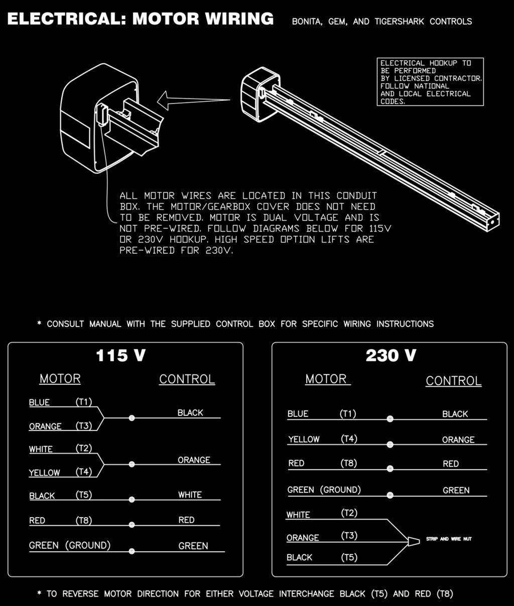
15 Page 15
16 Page 16 Imm Quality Boat Lifts Contact Information Phone: (239) Toll Free: Fax: (239) Website: iqboatlifts.com Sales: General Inquiries:
Installation Manual. For. Hi-Speed Alumavator / Platinum Vertical Boat Lifts
 Installation Manual For Hi-Speed Alumavator / Platinum Vertical Boat Lifts Page 2 Safety Precautions 1. Your boat lift is a heavy duty piece of equipment. It is important that all persons that may operate
Installation Manual. For. Alumavator / Platinum Boathouse Lifts
 Installation Manual For Alumavator / Platinum Boathouse Lifts Page 2 Safety Precautions 1. Your boat lift is a heavy duty piece of equipment. It is important that all persons that may operate this unit
Installation Manual. For. Alumavator and Platinum. Vertical Installation. Elevator Boat Lifts
 Installation Manual For Alumavator and Platinum Vertical Installation Elevator Boat Lifts Page 2 Safety Precautions 1. Your boat lift is a heavy duty piece of equipment. It is important that all persons
Installation Manual. For. PWC 3000 Boat Lifts
 Installation Manual For PWC 3000 Boat Lifts Page 2 Safety Precautions 1. Your boat lift is a heavy duty piece of equipment. It is important that all persons that may operate this unit have read and understood
Installation Manual. For. High Speed Alumavator and Platinum. 10 and 23 Degree. Elevator Boat Lifts
 Installation Manual For High Speed Alumavator and Platinum 10 and 23 Degree Elevator Boat Lifts Page 2 Safety Precautions 1. Your boat lift is a heavy duty piece of equipment. It is important that all
vertical cradle lifts installation instructions
 vertical cradle lifts installation instructions models 7,000 lb. thru 45,000 lb. important: read this manual before beginning installation of cradle lift. 5560 Ulmerton Road Clearwater, Florida 33760 1.800.878.5560
A B C D E F. Tools Required (supplied by others)
") Page 1 of 17 Parts List Below Deck Automatic Retractable Security Cover Kit (1) Tube End Bearing Plate (A) (1) Rope Reel and Cover Drum Motor Assembly (B) (1) Cover Drum (1) Pulley Support Channel (2)
Page 1 of 17 Parts List Below Deck Automatic Retractable Security Cover Kit (1) Tube End Bearing Plate (A) (1) Rope Reel and Cover Drum Motor Assembly (B) (1) Cover Drum (1) Pulley Support Channel (2)
A B C D E F. b.tools Required (supplied by others) 3/16" Drill Bit 3/8" Wrench Phillips Head Screwdriver
 3/16 Drill Bit 3/8 Wrench Phillips Head Screwdriver") Page 1 of 13 5E.1 Parts List a. Below Deck Automatic Retractable Security Cover Kit (1) Tube End Bearing Plate (A) (1) Rope Reel with Motor Attached (B) (1) Rope Reel Cover (C) (1) Cover Drum (1) Cover
Page 1 of 13 5E.1 Parts List a. Below Deck Automatic Retractable Security Cover Kit (1) Tube End Bearing Plate (A) (1) Rope Reel with Motor Attached (B) (1) Rope Reel Cover (C) (1) Cover Drum (1) Cover
PW Cantilever Lift: Part Number: Instructions and Safety Tips 1200 Ibs Capacity
 www.shoremaster.com 1200 PW Cantilever Lift: Part Number:1017507 Instructions and Safety Tips 1200 Ibs Capacity 1. 2. 3. 4. 5. CAUTION - PUT SAFETY FIRST Before attempting to install or operate this hoist,
Installation Instructions Table of Contents
 Installation Instructions Table of Contents Pre- Installation of Garage Storage Lift 2 Layout the Garage Storage Lift 3 Installing the strut Channels 3 Install the Drive Assembly 5 Install the Drive Shaft
Pontoon Assembly Instructions and manual. Read before using hoist.
 Page 1 Pontoon Assembly Instructions and manual. Read before using hoist. For Models 32BL18, 32BL22, 32BL25 and 42BL28 R Model 32BL22 Shown Proudly Made in Michigan By NuCraft Metal Products 402 Southline
Boat Hoist USA. General information and guides for installing a hoist lift system onto an existing overhead structure.
 Boat Hoist USA General information and guides for installing a hoist lift system onto an existing overhead structure. Structures built on the water vary depending on the geographic location. Below represent
INSTALLATION INSTRUCTIONS
 INSTALLATION INSTRUCTIONS FIX MARINE SUPPLY (866) 998-3625 1,5OO Lb. Capacity Special Notes: Improper installation-assembly, or overloading PWC lift beyond rated capacity will void manufacturer s warranty.
Aluminum Boat House Lift 8K and 4K Side mount INSTALLATION MANUAL
 Aluminum Boat House Lift 8K and 4K Side mount INSTALLATION MANUAL Made in the USA! Beltless Drives! All Aluminum! No Weld Cradles! BH-USA - Longview Texas 800-259-8175 Fax (903) 758-3646 www.bh-usa.com
Installation Instructions. Attention Dealers: Please give this owners manual to the customer when the product is delivered.
 Serving the Truck & Trailer Industry Since 1944 Attention Dealers: Please give this owners manual to the customer when the product is delivered. Call 800-535-9545 www.aeroindustries.com Indianapolis, IN
Midwest Industries, Inc. Ida Grove, IA Page 1
 SSV40108HAC - Hydraulic Hoist with 120 Volt Pump SSV40108HDAC - Hydraulic Hoist, Deep Water, with 120 Volt Pump SSV40108HDC - Hydraulic Hoist with 12 Volt Pump SSV40108HDDC - Hydraulic Hoist, Deep Water,
Rotating PWC Lift Installation Guide
 Rotating PWC Lift Installation Guide 800 259 8715 www.boathoistusastore.com BHUSA PWC Lift Installation Guidelines by Boat Hoist USA Check all parts on the packing list to ensure you have all the parts
Siderolling Tarp Systems Under 9 6 Wide
 Load Loc Select Maximizer Grain Carts Grain Bagger Siderolling Tarp Systems Under 9 6 Wide CRANK STYLE INSTALLATION INSTRUCTIONS MICHEL S INDUSTRIES, LTD. P.O. BOX 119 ST. GREGOR, SK. S0K 3X0 PH:306.366.2184
INSTALLATION INSTRUCTIONS
 INSTALLATION INSTRUCTIONS Thank you for purchasing an AUTOLOCK Electric Tarp. ACI proudly manufactured this product using superior quality materials and workmanship. With proper care, your tarp will provide
LPE C5 Battery Relocation Kit
 LPE C5 Battery Relocation Kit The LPE C5 Corvette battery relocation kit improves vehicle weight distribution by moving weight to the rear of the vehicle. The improved weight distribution increases traction
DC Series Installation Manual (# )
") DC Series Installation Manual (# 101630) Page 1 of 33 In this booklet you will find: TOWER INSTALLATION... 3 U-Bolt Style mount... 4 Side Frame Style mount... 4 PIVOT INSTALLATION... 5 External Pivot Installation:
DC Series Installation Manual (# 101630) Page 1 of 33 In this booklet you will find: TOWER INSTALLATION... 3 U-Bolt Style mount... 4 Side Frame Style mount... 4 PIVOT INSTALLATION... 5 External Pivot Installation:
Easy Cover. Installation Instructions. Attention Dealers: Please give this owners manual to the customer when the product is delivered.
 Serving the Truck & Trailer Industry Since 944 Easy Cover Attention Dealers: Please give this owners manual to the customer when the product is delivered. Call 00-3-94 www.aeroindustries.com Indianapolis,
INSTALLATION MANUAL FOR PILOT WORKSTATION
 INSTALLATION MANUAL FOR PILOT WORKSTATION Weight Capacity: 5-25 lbs. Monitor Weight: 5-20 lbs. 6011180 Rev. B Contents Tools Required / Supplied Part Kits / Warnings/Disclaimer...2 Possible Base Mounting
Installation Instructions
 Installation Instructions ELECTRIC CONVERSION KIT 3 ALUMINUM ROLL TUBE IMPORTANT: This Electric Conversion Kit has been designed for systems with a 3 aluminum roll tube. It is assumed that the tarping
How to Install a Garage Door Opener
 How to Install a Garage Door Opener While installing a garage door opener is a relatively straightforward project, the installation process is too detailed - and too manufacturer-specific - to be covered
SUT-250-S (These instructions are used for SUT-250-SCLC also)
") SUT-250-S (These instructions are used for SUT-250-SCLC also) Torque wrench, carpenters square, wire cutters, Phillips screwdriver, 7/16, 9/16, and 3/4 combination wrenches, ratchet, 9/16, 3/4, 13/16,
SUT-250-S (These instructions are used for SUT-250-SCLC also) Torque wrench, carpenters square, wire cutters, Phillips screwdriver, 7/16, 9/16, and 3/4 combination wrenches, ratchet, 9/16, 3/4, 13/16,
ES-6500V ES-6500P ES-6500W 915 W.
 INSTALLATION MANUAL E-Series MODELS ES-6500V ES-6500P ES-6500W R HydroHoist Marine Group, Inc. 915 W. Blue Starr Dr. Claremore, OK 74017 1-800-825-3379 Pub. May, 2014 Publication May 2014 HydroHoist Marine
KWSL2000RM ! CAUTION!! READ AND UNDERSTAND THIS MANUAL BEFORE INSTALLATION AND OPERATION OF THIS PRODUCT. DO NOT RETURN THIS PRODUCT TO SELLER.
 Assembly & Operating Instructions KWSL2000RM 2000 Lb. 12VDC Electric Winch! CAUTION!! READ AND UNDERSTAND THIS MANUAL BEFORE INSTALLATION AND OPERATION OF THIS PRODUCT. DO NOT RETURN THIS PRODUCT TO SELLER.
TABLE OF CONTENTS 3-7. Exploded View Assembly Cable Location and Adjustment Installation and Operation
 www.shoremaster.com DVS Vertical Lift (Double V Side): Frame ssembly Instructions. Models: 0DVS ft Wide, 00lb Capacity Part #: 07 009DVS 9ft Wide, 000lb Capacity Part #: 0070 00DVS 0ft Wide, 000lb Capacity
Important Information
 Boat Lift Boss Installation Instructions For Metal Craft Lifts (Kit 3005.7204) Important Information Before installation, read and understand all instructions and warnings. All 120 Volt units MUST have
C C30120 Canopy Instructions
 C17100 - C30120 Canopy Instructions Assembly Instructions Parts & Hardware List CAUTION: Please read this manual thoroughly before attempting to operate you canopy. Please be sure you understand and follow
CAUTION - PUT SAFETY FIRST
 www.shoremaster.com DVS Vertical Lift (Double V Side): Frame ssembly Instructions. Models: 00DVS 0ft Wide Pontoon, 000 Capacity Part #: 0 0(with Pontoon Guide/Cradles) 00DVS 0ft Wide, 000lb Capacity Part
FARM MODEL INSTALLATION INSTRUCTIONS
 REAR ATTACHMENT ELECTRIC CONVERSION FARM MODEL INSTALLATION INSTRUCTIONS This page intentionally left blank MICHEL S INDUSTRIES, LTD. p.o. Box 119 St. GREGOR,SK PH: 306.366.2184 em: SALES@MICHELS.CA 1
Installation Instructions
 Installation Instructions TrailView Soft Top Important Safety Information For proper installation and best possible fit, please read all instructions BEFORE you begin. Periodically check all components
WATER PUMP INSTALLATION INSTRUCTIONS WEIAND WATER PUMPS ACTION PLUS & TEAM G APPLICATIONS FOR SMALL BLOCK & BIG BLOCK CHEVROLETS
 WATER PUMP INSTALLATION INSTRUCTIONS WEIAND WATER PUMPS ACTION PLUS & TEAM G APPLICATIONS FOR SMALL BLOCK & BIG BLOCK CHEVROLETS APPLICATIONS: Weiand Action Plus aluminum water pumps are designed for street/performance
Adjustable Light Kits E-Z-Go TXT All Models Installation Instructions
 Adjustable Light Kits E-Z-Go TXT All Models 1996-2013 Installation Instructions Caution: Please read through the instructions carefully. Before starting this project, remove the system s positive and negative
MASTERsine Inverter PXA Series Installation Guide
 Backup Power System Expert TM MASTERsine Inverter PXA Series Installation Guide Important Safety Instructions IMPORTANT: Read and save this Installation Guide for future reference. This chapter contains
OPERATOR S MANUAL. 20-bu 3-Point Hitch Material Collection System. LP65048 Supplier ST /07/2017 English. North American Edition Printed in USA
 OPERATOR S MANUAL 20-bu 3-Point Hitch Material Collection System LP65048 Supplier ST48289 11/07/2017 English North American Edition Printed in USA Introduction Using Your Operator s Manual Read this entire
Pontoon Assembly Manual Read before using hoist
 Page 1 Pontoon Assembly Manual Read before using hoist For Models 32BL18, 32BL22, 32BL25 and 42BL28 R Model 42BL25 Shown Proudly Made in Michigan By NuCraft Metal Products 402 Southline Rd. Roscommon,
INSTALLATION MANUAL. UltraLift UL2. MODELS UL2 through UL W. Blue Starr Dr. Claremore, OK (918) Pub.
 Pub.") INSTALLATION MANUAL UltraLift UL2 MODELS 10000 UL2 through 32000 UL2 915 W. Blue Starr Dr. Claremore, OK 74017 (918)341-6811 Pub. :4/27/17 HydroHoist Marine Group HydroHoist Marine Group Product Installation
INSTALLATION MANUAL UltraLift UL2 MODELS 10000 UL2 through 32000 UL2 915 W. Blue Starr Dr. Claremore, OK 74017 (918)341-6811 Pub. :4/27/17 HydroHoist Marine Group HydroHoist Marine Group Product Installation
Installation Instructions COMPETITION/PLUS SHIFTER Ford Mustang MT82 6-Speed Manual Transmission Catalog#
 Installation Instructions COMPETITION/PLUS SHIFTER 2015-2017 Ford Mustang MT82 6-Speed Manual Transmission Catalog# 3916037 Rev. 00 WORK SAFELY! For maximum safety, perform this installation on a clean,
AL625 & AL625HD INSTALLATION & OWNER S MANUAL
 AL625 & AL625HD INSTALLATION & OWNER S MANUAL These instructions are provided to assist you in the installation of the AL625. If you require further assistance, our trained staff is ready to provide you
4' x 10' Assembly Instructions. We re Here To Help! Call Toll Free Section Roll In Dock Shown
 4' x 10' Assembly Instructions TM 4 Section Roll In Dock Shown We re Here To Help! Call Toll Free 1-888-752-9782 Customer Service: Monday - Friday, 8:00 A.M. to 5:00 P.M. C.S.T. TABLE OF CONTENTS - ALUMINUM
Section 13. Tail Rotor Drive. RotorWay International A600 TALON Construction Manual. Section 13. Page A
 RotorWay International Page A Tail Rotor Drive Procedures covered in this section: Install driveshafts and gearboxes; install drive belt and tensioner; fabricate and install tail rotor pitch actuator arms;
Installation Instructions I - Sheet Number I-TVR-01 Rev. A
 Installation Instructions I - Sheet Number I-TVR-01 Rev. A TrailView Soft Top For proper installation and best possible fit, please read all instructions BEFORE you begin. For technical assistance or to
Adult Car Plans. A comprehensive guide to help you build an official Soap Box Derby Adult Car
 Adult Car Plans A comprehensive guide to help you build an official Soap Box Derby Adult Car 1 Table Of Contents Introduction...Page 3 Adult Car Floorboard...Page 4 Step One Steering Stop Installation...Page
INSTALLATION INSTRUCTIONS
 INSTALLATION INSTRUCTIONS ----1075 North Ave. Sanger, CA 93657-3539 toll free: 800-445-3767 web: www.belltechcorp.com---- 5052 AIR JACK 94-99 DODGE ½ TON RAM C-1500 Congratulations! You were selective
HP BladeSystem c7000 Carrier-Grade Options Installation Guide
 HP BladeSystem c7000 Carrier-Grade Options Installation Guide Part Number 5991-8062 September 2009 (Second Edition) Copyright 2009 Hewlett-Packard Development Company, L.P. The information contained herein
SUT-450-I ASSEMBLY REQUIREMENTS
 SUT-450-I Torque wrench, carpenters square, wire cutters, Phillips screwdriver, 7/16, 9/16, and 3/4 combination wrenches, ratchet, 9/16,3/4,13/16, and 7/8 sockets. ASSEMBLY REQUIREMENTS *Torque all T-bolt
INSTALLATION INSTRUCTIONS
 270 INSTALLATION INSTRUCTIONS 5-6 ! IMPORTANT PLEASE DON T HURT YOURSELF, YOUR KIT OR YOUR VEHICLE. TAKE A MINUTE TO READ THIS IMPORTANT INFORMATION. This kit is to be used on a pickup truck only, and
INSTALLATION MANUAL. UL2 Front Mount MODELS 4400 FM 6600 FM
 INSTALLATION MANUAL UL2 Front Mount MODELS 4400 FM 6600 FM R HydroHoist Boat Lifts HydroHoist Marine Group P.O. Box 1286 Claremore, OK USA 74018 1-800-825-3379 www.boatlift.com Pub. 10/14/08 HydroHoist
LIGHT DUTY ROLL UP DOOR
 1-800-225-6729 LIGHT DUTY ROLL UP DOOR CAUTION Use proper lifting equipment and correct lifting procedures to avoid damage or injury. MODEL 150C installation guide A rolling door is a large heavy object
BL400 Bed Lift. Warning! This bed lift is a very powerful tool and if used improperly could result in serious injury or death.
 BL400 Bed Lift Warning! This bed lift is a very powerful tool and if used improperly could result in serious injury or death. Be aware that this bed will raise and also lower with crushing force, and has
Easy Cover. Installation Instructions. Attention Dealers: Please give this owners manual to the customer when the product is delivered.
 Serving the Truck & Trailer Industry Since 1944 Model 9 10 Spring Flange Mount Easy Cover Attention Dealers: Please give this owners manual to the customer when the product is delivered. Call 800-3-94
MIC210 Electric Farm Conversion Instructions
 MIC210 Electric Farm Conversion Instructions Note: Apply the supplied Dielectric Lubricant to all wire connections when each wire is hooked up. The Dielectric Lubricant will help to prevent corrosion.
L/6.7L DODGE CUMMINS
 6/15/2016 #1050310D 2005-09 5.9/6.7 Dodge Cummins FlowMAX Lift Pump Kit (I-00170) - 1-2005-09 5.9L/6.7L DODGE CUMMINS BD FLOWMAX LIFT PUMP KIT Installation Instructions P/N # 1050310D PLEASE READ ALL INSTRUCTIONS
Materials List: Tools List:
 Materials List: Anchor assembly Automated power supply Automated power supply hardware packet Automation bracket assembly Automation bracket assembly hardware packet Automation winch assembly Cable Cable
JEEVES. JEEVES Installation Manual. Installation Manual The Easiest Do-It-Yourself Dumbwaiter on the Market
 1 888-323-8755 www.nwlifts.com JEEVES Installation Manual The Easiest Do-It-Yourself Dumbwaiter on the Market This manual will cover the installation procedure step-by-step. The installation of this dumbwaiter
Chain/Belt Drive Models PRE-INSTALLATION CONSIDERATIONS
 38968503545. 08/2017 ASSEMBLY/INSTALLATION Chain/Belt Drive Models PRE-INSTALLATION CONSIDERATIONS This opener includes parts and supplies needed for installation in most garages and on most garage doors.
INSTALLATION INSTRUCTIONS
 INSTALLATION INSTRUCTIONS "Elevate your storage needs to a Higher Level" MODEL # ASL-500 Aladdin Storage Lift, LLC. Aladdin 61 Shields StorageRoad Lift, LLC. Huntsville, AL 35811 Phone (256) 429-9700 Fax
INSTALLATION MANUAL SHALLOW WATER. HydroHoist Boat Lifts HydroHoist Marine Group P.O. Box 1286 Claremore, OK USA
 INSTALLATION MANUAL SHALLOW WATER MODEL 5000 R HydroHoist Boat Lifts HydroHoist Marine Group P.O. Box 1286 Claremore, OK USA 74018 1-800-825-3379 www.boatlift.com Pub. 01/12/09 Publication 01/12/09 HydroHoist
N. 15th Street, Middlesboro, KY TARP-N-GO SYSTEMS INSTALLATION INSTRUCTIONS
 1-800-248-7717 1002 N. 15th Street, Middlesboro, KY 40965 TARP-N-GO SYSTEMS INSTALLATION INSTRUCTIONS Congratulations on your purchase of a Mountain Tarp Tarp-N-Go tarping system. With tarping systems
Trackstar Motorized Folding Shade Installation Instructions
 Trackstar Motorized Folding Shade Installation Instructions Thank you for purchasing your new Trackstar folding shade. It has been custom-made from the highest quality materials to the dimensions you specified.
INSTRUCTIONS 360 Y-DROP
 INSTRUCTIONS 60 Y-DROP 60 Y-DROP REGISTRATION Please visit productregistration.60yieldcenter.com to complete the product registration for your 60 Y-DROP so we can better support our products from day one
BEAMER MODEL VDC Spotlight with joystick control panel MODEL VDC Spot/flood light with joystick control panel
 formerly a marinco.com product 502-2 installation & 503-2 instructions 502-2 24 VDC Spotlight with joystick control panel 502-3 24 VDC Spot/flood light with joystick control panel BEAMER MODEL 502-2 24
INSTRUCTIONS 360 Y-DROP
 INSTRUCTIONS 60 Y-DROP 60 Y-DROP REGISTRATION Please visit productregistration.60yieldcenter.com to complete the product registration for your 60 Y-DROP so we can better support our products from day one
Van Rack Installation Manual Dodge ProMaster
 1.888.772.8400 Big to small... We do it all Van Rack Installation Manual Dodge ProMaster Thank you for your purchase of an Unruh Fab Van rack. We have designed and built this rack so that you can easily
VHM-P (Non-Locking) and VHM-PL (Locking) Variable Height Arm with Slide-In Mounting Plate
 and VHM-PL (Locking) Variable Height Arm with Slide-In Mounting Plate") 3875 Cypress Drive Petaluma, CA 94954 800.228.2555 +1.707.773.1100 Fax 707.773.1180 www.gcx.com VHM-P (Non-Locking) and VHM-PL (Locking) Variable Height Arm with Slide-In Mounting Plate (Refer to qualified
3875 Cypress Drive Petaluma, CA 94954 800.228.2555 +1.707.773.1100 Fax 707.773.1180 www.gcx.com VHM-P (Non-Locking) and VHM-PL (Locking) Variable Height Arm with Slide-In Mounting Plate (Refer to qualified
Model 377, 379, 386, 388, Sleeper no window
 Installation Manual Model 377, 379, 386, 388, 389 63 Sleeper no window 2390 Blackhawk Road P.O. Box 6007 Rockford, IL 61125 www.nitesystem.com 1-866-204-8570 NITE Plus Installation Procedures 1-2 Table
**DO NOT EXCEED RECOMMENDED VEHICLE TOWING WEIGHT!** FORD F-250, F-350
 6065 SUBKIT 7/7/0 **DO NOT EXCEED RECOMMENDED VEHICLE TOWING WEIGHT!** FORD F-50, F-50 PAGE OF WARNING!! BRAKE, FUEL, AND ELECTRICAL LINES MAY NEED TO BE LOOSENED OR REPOSITIONED TO PROVIDE CLEARANCE FOR
Ram 1500 Crew Cab A Ram 2500/3500 Crew Cab A
 I N S T A L L A T I O N G U I D E APPLICATION AMP Part # Ram 1500 Crew Cab 2013-2015 77138-01A Ram 2500/3500 Crew Cab 2013-2015 77138-01A Note:The application works only on the Crew Cab model Vehicles.
INSTALLATION MANUAL. Melink Corporation (513) Revision
 Revision") INSTALLATION MANUAL Revision 130711 Table of Contents Step Installation Contractor Page 1 Install System Controller Electrical 4 2 Install Variable Frequency Drive Electrical 6 3 Install Touchpad Mechanical
INSTALLATION MANUAL Revision 130711 Table of Contents Step Installation Contractor Page 1 Install System Controller Electrical 4 2 Install Variable Frequency Drive Electrical 6 3 Install Touchpad Mechanical
3875 Cypress Drive Petaluma, CA Fax
 3875 Cypress Drive Petaluma, CA 94954 800.228.2555 +1.707.773.1100 Fax 707.773.1180 www.gcx.com VHM-P (Non-Locking) Variable Height Arm with Fixed Angle Front End for Flat Panel / Keyboard Bracket (L Brackets
**DO NOT EXCEED RECOMMENDED VEHICLE TOWING WEIGHT!** FORD F-250, F-350
 60647 SUBKIT 7/3/204 **DO NOT EXCEED RECOMMENDED VEHICLE TOWING WEIGHT!** FORD F-250, F-350 PAGE OF 4 WARNING!! BRAKE, FUEL, AND ELECTRICAL LINES MAY NEED TO BE LOOSENED OR REPOSITIONED TO PROVIDE CLEARANCE
Kit No Please read these instructions completely before proceeding with installation. Air Spring Kit Parts List. Bracket Attaching Hardware
 Kit No. 59532 MN-572 (021108) ECR 7136 Please read these instructions completely before proceeding with installation Air Spring Kit Parts List A Item Description Quantity A Air Sleeves 2 B Upper Brackets
Combine Cover Manual
 Combine Cover Manual Installation Instructions Page 27 Operating Instructions Page 8 Warranty Page 8 Trouble Shooting Page 9 11 For Model s: Case I.H. 2388, 2188, 1688 and 1680 With a MAURER Hopper Extension
Page 1. File: Motolight caliper one-piece Date: 8/14/2006
 Page 1 Caliper Mount Installation One-piece mounting brackets You should allow about two to three hours for installation. We suggest you use a well-lighted space for installation. PLEASE READ ALL THE INSTRUCTIONS.
LINE PULLER. Installation Maintenance Use and Safety
 The Way To Fish LINE PULLER Installation Maintenance Use and Safety CAUTION! Read through this entire booklet before operating your Scotty Line Puller. Improper use may damage your Line Puller and void
LGT-312L E-Z-Go TXT Light Bar Bumper Kit Installation Instructions
 LGT-312L E-Z-Go TXT 2014+ Light Bar Bumper Kit Installation Instructions Caution: Please read through the instructions carefully. Before starting this project, remove the system s positive and negative
**DO NOT EXCEED RECOMMENDED VEHICLE TOWING WEIGHT!**
 60660 SUBKIT 7/8/0 **DO NOT EXCEED RECOMMENDED VEHICLE TOWING WEIGHT!** DODGE 500 / 3500 SHORT AND LONG BED PAGE OF 5 WARNING!! BRAKE, FUEL, AND ELECTRICAL LINES MAY NEED TO BE LOOSENED OR REPOSITIONED
Top Down Rollstar Shade Installation Instructions
 Top Down Rollstar Shade Installation Instructions Thank you for purchasing your new Rollstar shade. It has been custom-made from the highest quality materials to the dimensions you specified. With proper
Installationn Instruction Manual
 Table of Contents Supplied Kit Parts.Page 2 Required Tool List Page 2 Step by Step Installation Instructions Pages 3-6 Battery Requirements.Page 6 Operation Page 7 Maintenance Page 7 Wiring Diagrams..Page
Please visit for the latest version of these installation instructions.
 Please visit www.blueox.com for the latest version of these installation instructions. BX2338 2012-17 Hyundai Accent GLS/SE (Includes Foglights) Attachment Tab Height: 14 Serial Number Attachment Tab Width:
PLEASE READ THIS INSTRUCTIONS CAREFULLY, BEFORE YOU START INSTALLATION
 INSTALLATION INSTRUCTIONS PART NUMBER: L0SXC000 DESCRIPTION: 09 ASCENT TRAILER HITCH PLEASE READ THIS INSTRUCTIONS CAREFULLY, BEFORE YOU START INSTALLATION SAFETY PRECAUTION: When installing Trailer Hitch,
INSTALLATION INSTRUCTIONS
 2705 INSTALLATION INSTRUCTIONS 5-6 ! IMPORTANT PLEASE DON T HURT YOURSELF, YOUR KIT OR YOUR VEHICLE. TAKE A MINUTE TO READ THIS IMPORTANT INFORMATION. This kit is to be used on a pickup truck only, and
Center Drive Tube. Gussets
 O P E R A T O R S M A N U A L EZ-GLIDE SYSTEM ALUMINUM DROP DOWN LADDER RACK Read and understand all WARNINGS, DANGERS, NOTICES and instructions before assembly and installation. WARNING MODEL 251-3-02,
Van Rack Installation Manual Ford Transit Connect
 1.888.772.8400 Big to small... We do it all Van Rack Installation Manual Ford Transit Connect Thank you for your purchase of an Unruh Fab Van rack. We have designed and built this rack so that you can
Southwest Windpower Instruction Sheet AIR-X Circuit Replacement Kit
 Southwest Windpower Instruction Sheet AIR-X Circuit Replacement Kit Tools Required 5 / 32 Hex key 5 / 16 Hex key 7 / 64 Hex key Standard screwdriver Pair of external snap ring pliers Rubber mallet Hammer
General Front Windshield
 General Front Windshield **WATCH OUR INSTALL VIDEO ALONG WITH INSTALL SHEET. 8-5/16-18x1 Black Carriage Bolts 8-5/16 Black Nylock Nuts 2-5/16x1-1/4 Stainless Steel Socket Head Screws 2-Rubber Grommets
The Motor Ladder. Installation Instructions
 The Motor Ladder Installation Instructions Receiving The Ladder is delivered by common carrier (truck line). Check carefully on delivery that all items are received and that the ladder is free of any damage.
JK HD Skid Plate for Rear Falcon Shocks
 1 JK HD Skid Plate for Rear Falcon Shocks Kit # 36-07-01-300 Important Notes: Prior to beginning this or any installation read these instructions to familiarize yourself with the required steps and evaluate
B5 A4 1.8t Front Mount Intercooler Install Instructions
 B5 A4 1.8t Front Mount Intercooler Install Instructions Only work underneath your vehicle after properly supporting it with adequate jack stands on a flat surface. NEVER work under a vehicle only supported
INSTALLATION INSTRUCTIONS
 AUTOMOTIVE PRODUCTS, INC. INSTALLATION INSTRUCTIONS ULTIMATE BULL BAR APPLICATION: 2017 Ford F-250/350 PART NUMBER: 32-3900, 32-3905, 32-3900L, 32-3905L ITEM QUANTITY DESCRIPTION TOOLS NEEDED 1 1 ULTIMATE
RollSeal 1733 County Road 68 Bremen, Alabama Part No Rev Owner s Manual RS-Divider Curtain
 1. 2. 7 3. 4. RollSeal 1733 County Road 68 Bremen, Alabama 35033 256-287-7000 Part No 4801-5176 Rev 12-11-17 Owner s Manual RS-Divider Curtain Table of Contents 1 Warnings (Avertissements)... 3 2 Limited
Deuce/Ace Installation Instructions
 HARDWARE KIT: Upper Mounting Plate: 2-7/16" (11mm) X 3.5" bolts 2-7/16" flange nuts 2-2" spacers 2-7/16" trim cap mounting washers 2 - plastic trim caps TOOLS NEEDED: safety glasses wrenches 16mm or 5/8"
Model 3050 Installation Instructions. Model 3050 Electric Wall Installation Procedure
 Model 3050 Electric Wall Installation Procedure Effective August 2017 Special tools needed: Bondus type hex ball point tip Allen 7/32 Roller Chain tensioner Roller Chain breaker 1 7/8 open end wrench 15/16
F I R S T! Assembly* 4 Battery systems pull toward you, or 8 battery systems Lift up, both sides with a. Fig. B. *performed by licensed electrician
 All electrical work must be done in accordance with local, national and/or international electrical codes. Before installing or using this device, read all instructions and cautionary marking located (in
L DODGE CUMMINS BD FLOWMAX LIFT PUMP KIT
 6/15/2016 #1050311D 2010-12 6.7 Dodge Cummins FlowMAX Lift Pump Kit (I-00329) - 1-2010-12 6.7L DODGE CUMMINS BD FLOWMAX LIFT PUMP KIT Installation Instructions P/N # 1050311D PLEASE READ ALL INSTRUCTIONS
Installation Instructions INDY SHIFTER Fits: Mustang Fastback & Convertible with MT-82 Transmission Catalog #
 Installation Instructions INDY SHIFTER Fits: 2015-2018 Mustang Fastback & Convertible with MT-82 Transmission Catalog # 3916036 Watch our installation video on YouTube WORK SAFELY! For maximum safety,
Electric Vehicle Charging Station
 EVoReel Electric Vehicle Charging Station INSTALLATION GUIDE AND USER MANUAL Model: Dual Output Pedestal Mount 30A EVoReel EVSE Model Numbers: With Basic EVSE: EV072-400-002A; With Intelligent ievse: EV072-410-002A;