PARTS-WIRING TECHNICAL MANUAL MSHA PERMISSABLE CONTROLS CB-801 CB-8218
|
|
|
- Godwin Harrell
- 5 years ago
- Views:
Transcription


1 PARTS-WIRING TECHNICAL MANUAL MSHA PERMISSABLE CONTROLS CB-80 CB-88
2 TABLE OF CONTENTS TABLE OF CONTENTS... SAFETY WARNING!... 3 EXPLOSION PROOF ELECTRICAL EQUIPMENT - HAZARD WARNINGS... 4 STANCOR PERMISSIBLE CONTROLS DESCRIPTION... 5 MANUAL CONTROLS... 5 AUTOMATIC CONTROLS (FLOATS)... 5 AUTOMATIC CONTROLS (FLOATLESS)... 5 Important: Notice... 5 SERVICING THE MSHA MANUAL AND AUTOMATIC CONTROL... 6 Model CB-80 Service/Inspection... 6 Model CB-88 Service/Inspection... 6 Trouble Shooting... 7 Model CB-88 Floatless Service/Inspection WIRING DIAGRAM... 8 STANCOR MODEL CB-80 PARTS LIST... 9 STANCOR MODEL CB-80 EXPLODED VIEW... 0 CB-80 DIMENSIONS... CB-88 DIMENSIONS LAYOUT DRAWING WIRING DIAGRAM WIRING DIAGRAM(Alternate I/S Relay) FLOATLESS WIRING DIAGRAM... 6 STANCOR MODEL CB-88 PARTS VIEW... 7 STANCOR MODEL CB-88 PARTS LIST... 8 STANCOR MODEL CB-88 PARTS LIST (Cont.)... 9
3 SAFETY WARNING! Make sure the power is disconnected (locked off and tagged) before making the installation. Installation of Stancor Portable Permissible Controls should only be performed by a qualified electrician in accordance with the NEC, local Electrical Codes and MSHA regulations. The control should be securely mounted in an upright position, away from mud, water and dirt. Before connecting the power, verify that the supply voltage, phase and frequency matches with the volts, phase and Hz, shown on the control and pump data plates. Connect the pump cable and power leads as indicated on the wiring diagram, or see the corresponding wiring diagram in this manual. Prior to energizing the control, check all wiring connections to insure they are tight. Check and tighten all cover bolts. Check all cable entries for fit and tightness. ALWAYS DISCONNECT THE POWER SUPPLY TO THE CONTROL PRIOR TO UNSCREWING THE COVER BOLTS. NO CHANGES/MODIFICATIONS MAY BE MADE TO ANY MSHA APPROVED COMPONENTS WITHOUT PRIOR AUTHORIZATION FROM MSHA
4 EXPLOSION PROOF ELECTRICAL EQUIPMENT - HAZARD WARNINGS Caution Statement (Required by 30CFR PART 8) To retain permissibility of this equipment the following conditions shall be satisfied:. General Safety. Frequent inspection shall be made. All electrical parts, including the portable cable and wiring, shall be kept in a safe condition. There shall be no opening into the casings of the electrical parts. A permissible distribution box shall be used for connection to the power circuit unless connection is made in fresh intake air. The machine frame shall be effectively grounded. The operating voltage should match the voltage rating of the motor(s).. Servicing. Explosion-proof enclosures shall be restored to the state of original safety with respect to all flame arresting paths, lead entrances, etc. following disassembly for repair or rebuilding, whether by the owner or an independent shop. 3. Fasteners. All bolts, nuts, screws and other means of fastening, and also threaded covers, shall be in place, properly tightened and secured. 4. Renewals and Repairs. Inspections, repairs or renewals of electrical parts shall not be made unless the portable cable is disconnected from the circuit furnishing power, and the cable shall not be connected again until all parts are properly reassembled. Special care shall be taken in making renewals or repairs. Leave no parts off. Use replacement parts furnished by the manufacturer. When any lead entrance is disturbed, the original leads or exact duplicates thereof shall be used and stuffing boxes shall be repacked in the approved manner. 5. Cable Requirements. A flame resistant portable cable bearing a MSHA assigned identification number, adequately protected by an automatic circuit interrupting device shall be used. Special care shall be taken in handling the cable to guard against mechanical injury and wear Splices in portable cables shall be made in a workmanlike manner, mechanically strong, and well insulated. Not more than one temporary splice is permitted in a portable cable regardless of length. Connections and wiring to the outby end of the cable shall be in accordance with recognized standards of safety. "DO NOT CHANGE WlTHOUT PRIOR APPROVAL OF M.S.H.A". TITLE CAUTION STATEMEMT DRWG.NO. CB8344 DATE I 4/7/95
5 STANCOR PERMISSIBLE CONTROLS DESCRIPTION MANUAL CONTROLS At the present time Stancor supplies one version, of Permissible manual control: (Circuit Breaker/Overload circuit) This manual control version is built with a combination circuit breaker/overload/disconnect, allowing a threefold function: ( ) manual ON/ OFF switch; () motor short-circuit protection; (3) motor overload protection.the circuit breaker will trip when one of the above occurs. The breaker has to be manually reset. All Stancor 3-phase & -phase pump motors have built-in temperature sensors (normally closed thermal switches), wired in series, which open at a preset motor stator winding temperature and re-close after the temperature returns to a safe level. All Stancor P pumps are designed with a thermal switch monitoring circuit, that is, thermal switches are connected in series with a contactor coil mounted in the head of the pump. AUTOMATIC CONTROLS (FLOATS) Stancor Permissible automatic controls are used for the unattended operation of Stancor Permissible pumps. These controls are equipped with a magnetic contactor which controls the pump motor's ON and OFF operation. The contactor is energized by two Stancor level sensors, installed in the sump at selected "LOW' and "HIGH" liquid levels. The two level sensors are connected to the control circuit, using a latching type intrinsically-safe relay as interface. This relay is a solid state switching device and is MSHA approved for hazardous locations. The "High" level sensor automatically turns the pump on at a high level condition, the "Low" level sensor turns the pump off. AUTOMATIC CONTROLS (FLOATLESS) These controls are equipped with a Model 8 fully programmable solid state liquid level controller which controls the pump motor's ON and OFF operation via the contactor. The controller operates on the principle that when a pump is pumping liquid it will draw higher KW than when it operates in a snore condition. When the Model 8 senses the reduction in KW via the curent transformer it shuts the pump off. After a short period of time the control will switch the pump on again. The model 8 is self learning and continually adapts the operation of the pump to the rate of inflow to the sump. No float switches or external sensing devices are required for operation. See the operation manual for a full description of all features and function capabilities. Important: Notice ANY SUBSTITUTION OF MSHA APPROVED COMPONENTS REQUIRES THE NOTIFICATION AND RESUBMITTAL OF DOCUMENTATION TO THE APPROVAL AND CERTIFICATION CENTER OF MSHA PRIOR TO THE CHANGE.
6 SERVICING THE MSHA MANUAL AND AUTOMATIC CONTROL Because of the critical requirements and potentially explosive environments the Stancor MSHA Controls are to perform in, Stancor recommends that NO PARTS OF THE CONTROLS ARE TO BE REPAIRED ONLY REPLACED, with factory original parts that are certified for use in our control box assemblies. All electrical work should be performed by qualified personnel only Model CB-80 Service/Inspection The Stancor Model CB-80 Manual Control box requires no maintenance, only the periodic inspection to ensure that all bolts, washers and safety wire are in place and secure, and the strain relief clamps are securely fastened to the main body of the control and cables. Whenever a pump is removed from service for repair a full inspection of the box should be performed. This includes the machined surfaces of the cover and body, that the on/off handle operates freely (no sticking), and all threaded connections as well as proper ground and ground check hardware are in place. If any discrepancies are noted the appropriate component should be replaced, not repaired. If the circuit breaker trips, the pump should be immediately inspected in a non explosive environment for possible motor damage. Once the cause has been determined, the pump should be repaired or the circuit breaker replaced before returning the pump to service. Model CB-88 Service/Inspection The Stancor Model CB-88 Manual Control box requires no maintenance, only the periodic inspection to ensure that all bolts, washers and safety wire are in place and secure, and the strain relief clamps are securely fastened to the main body of the control and cables. Whenever a pump is removed from service for repair a full inspection of the box should be performed. This includes the machined surfaces of the cover and body, that the on/off handle operates freely (no sticking), and all threaded connections as well as proper ground and ground check hardware are in place. If any discrepancies are noted the appropriate component should be replaced, not repaired.
7 Trouble Shooting ) If the circuit breaker trips, the pump should be immediately inspected in a non explosive environment for possible motor damage. Once the pump has been determined to be operating properly, further inspection and testing of the control can be performed. If the pump requires repair, additional inspection of the contactor in the control should be made. Ensure the contacts operate freely and that the surfaces are free of pitting and excessive arcing. If excessive, replace contactor. The following checks/tests may only be performed in a non permissible environment. Some tests must be performed with live voltage. These tests must only be performed by a qualified electrician using the utmost care. Severe injury and/or death may occur if performed by unqualified personnel. ) If the pump fails to start when floats are activated: A) Check power source/supply B) Check for 5 volt from secondary side of transformer C) Check contactor for coil damage D) Check floats for physical damage and/or circuit continuity when inverted. Replace if faulty E) Check output signal from intrinsically safe relay. See relay supplied with control for specs replace if necessary Model CB-88 Floatless Service/Inspection ) If the circuit breaker trips, the pump should be immediately inspected in a non explosive environment for possible motor damage. Once the pump has been determined to be operating properly, further inspection and testing of the control can be performed. If the pump requires repair, additional inspection of the contactor in the control should be made. Ensure the contacts operate freely and that the surfaces are free of pitting and excessive arcing. If excessive, replace contactor. ) If the pump fails to start when relay is activated: A) Check power source/supply B) Check for 5 volt from secondary side of transformer C) Check contactor for coil damage D) Check that LED display is lit. Refer to supplemental Instructions provided with control for specific tests and parameters 3) If pump starts/stops erratically, or continues to run excessively, consult factory for program data specific to model pump being used.
8 80 WIRING DIAGRAM
9 STANCOR MODEL CB-80 PARTS LIST MSHA APPROVED MANUAL CONTROL BOX POS. # QUANTITY PART # DESCRIPTION CB-87 RUBBER COLLAR CB-8 CABLE CLAMP (SET) 3 4 CB-809 BOLT S/S 5/6 X-3/4 4 CB-8 BOLT 3/8 X-/4 5 CB-83 3/8 LOCKWASHER NOT USED 7 CB-87 LOCKWIRE 8 CB-84 SHAFT W/FORK CB-84- (-DCE ONLY) 9 CB-83 N/A ROLL PIN (not available) 0 CB-84 ALLEN SET SCREW CB-8 SWITCH HANDLE CB-808 ON/OFF PLATE 3 8 CB-8 BOLT 3/8 X-/4 4 8 CB-83 3/8 LOCKWASHER 5 CB-89 CONTROL BOX COVER 6 CB-83 N/A COLLAR (not available) 7 CB-88 WASHER CB-89 CB-89A CB-89L BREAKER SCREW SHORT BREAKER SCREW LONG (-DCE BREAKER SCREW) 9 CB-* CIRCUIT BREAKER 0 4 CB-85 GROUND SCREW /4 X/ CB-86 GASKET 4 CB-8 WASHER 3 CB-805 PACKING, P-0 THRU S-000 CB-806 PACKING, P-60 THRU P-80 4 CB-80-6 CABLE ENTRY (ALL EXCEPT #) CB-840- CABLE ENTRY # TRAILING 5 - SEE PUMP PUMP CABLE 6 4 CB-85 WASHER 7 4 CB-80 LOCKWASHER 8 4 CB-8 HEX NUT 9 CB-804 CHAIN 30 CB-89-8 CONTROL BOX BODY 3 CB-807 NAME PLATE 3 CB-830 RIVET *REFER TO STANCOR CHART WITH THE PUMP MODEL AND VOLTAGE FOR MSHA APPROVED CIRCUIT BREAKER TYPE
10 STANCOR MODEL CB-80 EXPLODED VIEW MSHA APPROVED MANUAL CONTROL BOX
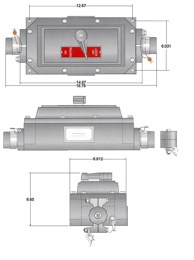
11 CB-80 DIMENSIONS
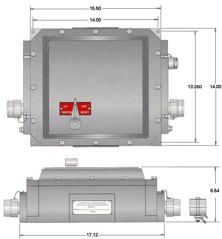
12 CB-88 DIMENSIONS
13 88 LAYOUT DRAWING
14 88 WIRING DIAGRAM TO MAIN CONTROL 460/575 Volt Junction Box
15 88 WIRING DIAGRAM (Alternate I/S Relay)
16 88 FLOATLESS WIRING DIAGRAM (TYPICAL)
17 STANCOR MODEL CB-88 PARTS VIEW Float Entry Assy. Junction Box Assy.
18 STANCOR MODEL CB-88 PARTS LIST MSHA APPROVED AUTOMATIC CONTROL BOX POS. # QUANTITY PART # CB-87 CB-8/ CB-8 CB-809 CB-8 CB-83 CB-87 CB-84- CB-83 N/A CB-84 CB-8 CB-808 CB-8 CB-83 CB-88- CB-88-F CB-83 N/A CB-88 N/A CB-89 CB-89A CB-* CB-85 CB-864 CB-8 CB-854 CB-855 CB CB-840- SEE PUMP CB-85 CB-80 CB-8 CB-804 CB-88- CB-88-3 CB-88-4 CB-807 CB-830 CB-86 CB-85/30 CB-85/460 CB-85/575 CB-858 CB-870 (CB-85) CB-860 CB-86 CB-850 CB-850/575 DESCRIPTION RUBBER COLLAR CABLE CLAMP SET # TRAILING CABLE CABLE CLAMP SET BOLTS/ S5/ 6 X-3/ 4 BOLT3/ 8 X-/ 4 3/ 8 LOCKWASHER NOT USED LOCKWIRE SHAFT W/FORK ROLL PIN (not available) ALLEN SET SCREW SWITCH HANDLE ON/OFF PLATE BOLT3/ 8 X-/ 4 3/ 8 LOCKWASHER CONTROL BOX COVER COVER FOR FLOATLESS COLLAR (not available) WASHER (does not apply) BREAKER SCREW SHORT BREAKER SCREW LONG CIRCUIT BREAKER (SPECIFY AMPS) ( GROUNDSCREW / 4 X/ )BACKPLATEBOLT BACKPLATE LOCK WASHER PACKING, STANDARD (SPECIFY PUMP MODEL) PACKING #, TRAILING CABLE CABLE ENTRY (ALL EXCEPT #) CABLE ENTRY # (TRAILING ONLY) PUMP CABLE WASHER LOCKWASHER HEX NUT CHAIN STANDARD BODY BODY WITH # TRAILING CABLE BODY FOR FLOATLESS VERSION NAME PLATE RIVET GROUND LUG TRANSFORMER 30/0 TRANSFORMER 460/0 TRANSFORMER 575/0 TIME RELAY (FLOATLESS ONLY) INTRINSICALLY SAFE RELAY WIRE RACEWAY FOR 88 TERMINAL BLOCK ASSY.(FLOAT ASSEMBLY) FLOATLESS CONTROL UNIT (30/460V) FLOAT LESS CONTROL UNIT (575V ONLY)
19 STANCOR MODEL CB-88 PARTS LIST (Cont.) MSHA APPROVED AUTOMATIC CONTROL BOX POS. # QUANTITY 5 3 PART # 5505/5 5500/ CB-853 CB CB-84A CB-84B 4/3 CB-856 CB-859 J4X-3 CB-857 SF 05 5 CB DESCRIPTION CONTACTOR UP TO 5 HP (5V COIL) CONTACTOR 0/30 HP FOR 460V PUMP (5V COIL) CONTACTOR SX4500 (5V COIL) PACKING (FLOAT CABLE) CABLE ENTRY FOR FLOATS BOLT FOR FLOAT ENTRY CABLE CLAMP CABLE CLAMP FOR FLOAT ENTRY RUBBER INSULATOR 4/ 3CABLE( 5 ) CABLEGLAND( 3/ 4 ) BUTT SPLICE JUNCTION BOX CABLEGLAND( / ) FLOAT SWITCH JUNCTI ONBOXASSY.W/5 4/3 CABLE, INCLUDING FLOAT SWITCHES AND J BOX, ALL PREWIRED *REFER TO STANCOR CHART WITH THE PUMP MODEL AND VOLTAGE FOR MSHA APPROVED CIRCUIT BREAKER TYPE February 008
20 STANCOR, INC. 55 FAN HILL ROAD MONROE, CT FAX
Installation, Operation and Maintenance Manual Stancor SSD & SL Series Pumps
 Installation, Operation and Maintenance Manual Stancor SSD & SL Series Pumps EI-700-008 Rev -- Table of Contents Safety Guidelines 3 Caution 4 Wiring 4 Maintenance 4 Nameplate format 4 Prior to Operation
Table 3. Pumping Range. 6 in cm. 8 in cm. 16 in cm. 6 in cm. 14 in cm. 18 in cm.
 float switches Mechanical Float Switch Mechanically activated float switches offer a reliable low current control for dewatering applications. How It Works The mechanical float switch control will turn
Trouble Shooting Guide EWA, 3-phase (D2422)
") Trouble Shooting Guide EWA, 3-phase (D2422) Trouble Shooting Guide Problem Possible Cause Possible Remedy Unit does not start Breaker tripped, no power to unit Loose wire Defective contactor or coil Close
Trouble Shooting Guide EWA, 3-phase (D2422) Trouble Shooting Guide Problem Possible Cause Possible Remedy Unit does not start Breaker tripped, no power to unit Loose wire Defective contactor or coil Close
Installation Instructions Electric Heaters 5 20 kw
 Small Packaged Products 2 to 5 Tons Accessory Electric Heaters Cancels: IIK 564A-24-2 IIK 564A-24- -02 Installation Instructions Electric Heaters 5 20 kw NOTE: Read the entire instruction manual before
Installation Instructions Electric Heaters 5 20 kw
 Small Packaged Products to 5 Tons Accessory Electric Heaters Cancels: IIK 564A--1 IIK 564A-- 11-01 Installation Instructions Electric Heaters 5 0 kw NOTE: Read the entire instruction manual before starting
Installation Instructions
 NOTE: Read the entire instruction manual before starting the installation. This symbol indicates a change since the last issue. SAFETY CONSIDERATIONS Installing and servicing air conditioning equipment
MODEL SCA Installation and Operation Manual Important:
 MODEL SCA Installation and Operation Manual Important: This manual contains specific cautionary statements relative to worker safety. Read this manual thoroughly and follow as directed. It is impossible
Surface Regulations and Policies
 Surface Regulations and Policies COAL FATALITIES 1970-2002 350 300 250 200 150 100 50 0 1970 1973 1976 1979 1982 1985 1988 1991 1994 1997 2000 From January 1, 1970 through today, a total of 240 coal miners
Installation, Operation and Maintenance Manual Stancor SE, SV, SS & SC Series Pumps
 Installation, Operation and Maintenance Manual Stancor SE, SV, SS & SC Series Pumps EI-700-005 Rev -- Table of Contents Safety Guidelines 3 Caution 4 Wiring 4 Maintenance 4 Nameplate format 4 Prior to
50 AMP TRANSFER RELAY DELAY - DUAL INPUT GENSET
 R 50 AMP TRANSFER RELAY DELAY - DUAL INPUT GENSET Transfer Relay Delay 00-00803-400 Dual Input Genset INDUSTRIAL CONTROL EQUIPMENT TYPE 1 Shore Power Rating: 120/240VAC 60HZ 1 Phase 50A/Pole Generator
B BASIC HEAT TREATMENT CONSOLE
 Maritime Stress PO Box 2898, 30 Estates Road Dartmouth, NS, B2W 4Y2, Canada Toll Free: 1-877-468-1781 Phone: (902) 468-7873 Fax: (902) 468-2304 Website: E-mail: info@maritimestress.com OPERATION MANUAL
COOKSON OWNER'S MANUAL
 COOKSON OWNER'S MANUAL FDO-A10 INDUSTRIAL DUTY FIRE DOOR OPERATOR R L I S T E D 3040233 US CONTROL PANEL SERIAL# OPERATOR SERIAL# 9001.DWG ECN 0959 REV 4 SPECIFICATIONS MOTOR TYPE:...INTERMITTENT HORSEPOWER:...1/8
Users Manual. Defender 1 8.0KW to 14.0KW Online Emergency Lighting Inverter. Technical Manual # Revision B
 Users Manual Defender 1 8.0KW to 14.0KW Online Lighting Inverter Technical Manual #018-0102-01 Revision B Phone: 1.877.DSPM.POWER 1.877.377.6769 Fax: 909.930.3335 Website: www.dspmanufacturing.com E-Mail:
Users Manual. Cobra Plus Stand-By Emergency Lighting Inverter. Technical Manual # Revision B
 Users Manual Cobra Plus Stand-By Lighting Inverter Technical Manual #018-0110-01 Revision B Phone: 1.877.DSPM.POWER 1.877.377.6769 Fax: 909.930.3335 Website: www.dspmanufacturing.com E-Mail: techsupport@dspmanufacturing.com
Axpert-CSS AMTECH DRIVES Axpert-CSS Amtech
 The Axpert-CSS is a range of Combination Soft Starter panels offered by AMTECH DRIVES. We also offer the module unit as an individual product, named as Axpert-Opti torque Soft Starter. This is only the
Best Diversified Products, Inc. Product Manual. BestReach Rigid Belt. Models BRB 230 OS BRB 230 SS BRB 460 OS BRB 460 SS
 Best Diversified Products, Inc. Product Manual TM BestReach Rigid Belt Models BRB 230 OS BRB 230 SS BRB 460 OS BRB 460 SS Best Diversified Products Inc. 107 Flint Street Jonesboro, AR 72401 Phone 870-935-0970
PBA Series Prelube Controls
 VARNA Products Engineered Innovation PBA Series Prelube Controls Simple, Compact, Industrial Full featured control for running prelube from the control or from a remote station Easy internal wiring connections
Instruction Bulletin. Jockey Pump Controller
 Instruction Bulletin Jockey Pump Controller Installation Start Up Service This instruction bulletin is a guide for personnel involved with maintenance, engineering and approval of Fire Pump equipment and
Quick Connection Panel (QCP) Installation Guide
 Installation Guide") Quick Connection Panel (QCP) Installation Guide DANGER HAZARD OF ELECTRICAL SHOCK, EXPLOSION, OR ARC FLASH Read this document first. The installer is responsible for compliance with National Electrical
Quick Connection Panel (QCP) Installation Guide DANGER HAZARD OF ELECTRICAL SHOCK, EXPLOSION, OR ARC FLASH Read this document first. The installer is responsible for compliance with National Electrical
A. Products shall be designed, manufactured, tested, and installed in compliance with the following standards:
 SECTION 26 29 13 ENCLOSED MOTOR CONTROLLERS PART 1 - GENERAL 1.1 RELATED DOCUMENTS: A. The Conditions of the Contract and applicable requirements of Divisions 0 and 1 and Section 26 00 01, Electrical General
INSTRUCTION MANUAL AND PARTS LIST FOR 3E CANNED MOTOR PUMPS
 TM INSTRUCTION MANUAL AND PARTS LIST FOR 3E CANNED MOTOR PUMPS WARNING This Special Instruction Manual and General Instructions Manual, CA-1, should be read thoroughly prior to pump installation, operation
331-SV. User Manual THREE PHASE DUPLEX LIFT STATION CONTROL PANEL WITH STATIONVIEW CONTROLLER. Ashland, OH
 331-SV User Manual THREE PHASE DUPLEX LIFT STATION CONTROL PANEL WITH STATIONVIEW CONTROLLER Ashland, OH 800-363-5842 WWW.PRIMEXCONTROLS.COM Warranty void if panel is modified. Call factory with servicing
 Motor Trouble-Shooting Chart Caution:. Disconnect power to the motor before performing service or maintenance.. Discharge all capacitors before servicing motor.. Always keep hands and clothing away from
Quick Start Guide TS 910 & TS 920
 Quick Start Guide TS 910 & TS 920 DANGER HAZARD OF ELECTRICAL SHOCK, EXPLOSION, OR ARC FLASH Read and understand this quick start guide before installing and operating the transfer switch The installer
Submersible Pumps Model ST4125D Model ST6125D
 OPERATION AND PARTS MANUAL Submersible Pumps Model ST5D Model ST65D Revision #0 (0/05/0) To find the latest revision of this publication, visit our website at: www.multiquip.com THIS MANUAL MUST ACCOMPANY
Requirements LEO Power Operator Installation Instructions Patents: 5,881,497; 7,316,096; 7,484,333 CAUTION CAUTION WARNING
 CAUTION 80-957-00-00 (08-0) Series 570 Door Openings 85 to 0 or to 80 Adjustable Arm and Slide Track Application Maximum Hinge Side Frame Reveal to /8 (mm) Hinge (Pull) Side of Door Installation 5700 LEO
Mount directly to 1.05 jackshafts. (new ZG-120 bracket shown) EFB24-S N4, EFX24-S N4(H) EFB24-S, EFX24-S (p. 21)
 EFB24-S N4, EFX24-S N4(H) EFB24-S, EFX24-S (p. 21)") EFB and EFX Series Spring Return Direct Coupled Actuator Minimum 70 in-lb Torque For damper areas up to 66 sq-ft* (For lower torque, see AFB, AF, NFB, LF, or TF series) Applications New standard clamp
EFB and EFX Series Spring Return Direct Coupled Actuator Minimum 70 in-lb Torque For damper areas up to 66 sq-ft* (For lower torque, see AFB, AF, NFB, LF, or TF series) Applications New standard clamp
This is intended to provide uniform application of the codes by the plan check staff and to help the public apply the codes correctly.
 SUPPLEMENTAL CORRECTION SHEET FOR SOLAR PHOTOVOLTAIC SYSTEMS (ELEC) This is intended to provide uniform application of the codes by the plan check staff and to help the public apply the codes correctly.
3 FT CORD Models , , , FT CORD W/GFCI Models , , ,
 POWERLINE XP II Swimming Pool Pump (Light Oak color model) With Automatic Timer 3 FT CORD Models 0-1395-226, 0-1396-226, 0-1397-226, 0-1398-226 25 FT CORD W/GFCI Models 0-1395-220, 0-1396-220, 0-1397-220,
Installation Instructions For Motor Control Center (MCC) Units
 Units") s Page 1 of 8 Installation Instructions December, 2013 Installation Instructions For Motor Control Center (MCC) Units Hazardous voltage. Will cause death or serious injury. Always de-energize and ground
s Page 1 of 8 Installation Instructions December, 2013 Installation Instructions For Motor Control Center (MCC) Units Hazardous voltage. Will cause death or serious injury. Always de-energize and ground
University of Houston Master Construction Specifications Insert Project Name
 SECTION 26 13 13 MEDIUM VOLTAGE SWITCHGEAR PART 1 - GENERAL 1.1 RELATED DOCUMENTS: A. The Conditions of the Contract and applicable requirements of Divisions 0 and 1 and Section 26 00 01, Electrical General
Instruction Sheet. 1/2 HP Portable Electric Pumps SAFETY FIRST. L2062 Rev. F 02/ IMPORTANT RECEIVING INSTRUCTIONS 2.
 Instruction Sheet 1/2 HP Portable Electric Pumps L2062 Rev. F 02/12 Index: English:...................................... 1-7 Français:.................................... 8-14 Deutsch:...................................
OpenEVSE - 40A Charging Station
 OpenEVSE - 40A Charging Station P50 Advanced P50 Standard http://www.openevse.com Read and save these instructions prior to installing and operating your Charging Station. Retain this installation guide
3 FT CORD UL/NEC Models , , , FT CORD w/gfci UL Models , , ,
 POWERLINE XP I Swimming Pool Pump (Light Oak color model) 3 FT CORD UL/NEC Models 0-1295-206, 0-1296-206, 0-1297-206, 0-1298-206 25 FT CORD w/gfci UL Models 0-1295-200, 0-1296-200, 0-1297-200, 0-1298-200
Ph: (07) Fax: (07) Pump Manual
 Fax: (07) Pump Manual") sales@scintex.com.au www.scintex.com.au Ph: (07) 3137 0135 Fax: (07) 3041 0541 Pump Manual 12V 75LPM Vane Pump & Vane Pump Station SPEP12V75 & SP12VFS75 SPEP12V75 SP12VFS75 Parts List No. Part Name QTY
sales@scintex.com.au www.scintex.com.au Ph: (07) 3137 0135 Fax: (07) 3041 0541 Pump Manual 12V 75LPM Vane Pump & Vane Pump Station SPEP12V75 & SP12VFS75 SPEP12V75 SP12VFS75 Parts List No. Part Name QTY
AIR CLEANERS Model MC 3000 OWNER S MANUAL CAUTION Read complete instructions before operating. Please file for future reference.
 AIR CLEANERS Model MC 3000 OWNER S MANUAL CAUTION Read complete instructions before operating. Please file for future reference. MODEL MC 3000 SPECIFICATION Input Volts: 208-230/430 VAC, 60Hz, 3 Phase
Instruction Manual. Q Series 2 Motor Control Modules - OEM
 A382-21-880 Issue B Instruction Manual Q Series 2 Motor Control Modules - OEM Pump/ Q Motor Control Module Item Number pumping system Electrical supply 24 V d.c. control 24 V a.c. control QDP40 200-230
MODEL MC1500 Installation and Operation Manual Important:
 MODEL MC1500 Installation and Operation Manual Important: This manual contains specific cautionary statements relative to worker safety. Read this manual thoroughly and follow as directed. It is impossible
MODEL 7100 PORTABLE PIN WELDER OPERATOR S MANUAL
 Model 7100 Portable Pin Welder MODEL 7100 PORTABLE PIN WELDER OPERATOR S MANUAL Copyright: March 22, 2005 Revised: December 20, 2016 Gripnail Corporation An Employee Owned Company 97 Dexter Road East Providence,
Remote Temperature Controller for Heated Mold Shoes, using a RTD/Digital Display, # C (version pre-2009).
.") Knowledge Base Article Type: Instructions Remote Temperature Controller for Heated Mold Shoes, using a RTD/Digital Display, #601127.C (version pre-2009). Description: Instructions on How to properly set-up
Knowledge Base Article Type: Instructions Remote Temperature Controller for Heated Mold Shoes, using a RTD/Digital Display, #601127.C (version pre-2009). Description: Instructions on How to properly set-up
KFE10010-E. Reclosers. Contents. Type KFVE and KFVME (27kV) Bus Bar Kit KRK710-1 Installation Instructions. Cooper Power Systems
 Bus Bar Kit KRK710-1 Installation Instructions. Cooper Power Systems") Reclosers Type KFVE and KFVME (27kV) Bus Bar Kit KRK710-1 Installation Instructions Cooper Power Systems Service Information Figure 1. Type KFVE and KFVME (27kV) bus bar kit KRK710-1. 961047KM Contents
Reclosers Type KFVE and KFVME (27kV) Bus Bar Kit KRK710-1 Installation Instructions Cooper Power Systems Service Information Figure 1. Type KFVE and KFVME (27kV) bus bar kit KRK710-1. 961047KM Contents
Cougar B Series Electric Vibrators 3 Frame
 Cougar B Series Electric Vibrators 3 Frame Go to Cougar B Series Electric Vibrators web page Operator s Manual M3929 Important MARTIN ENGINEERING HEREBY DISCLAIMS ANY LIABILITY FOR: DAMAGE DUE TO CONTAMINATION
80 Series 4 Post Brake Instructions
 Bulletin No. BK4604 (12/01) 80 Series 4 Post Brake Instructions Read carefully before attempting to assemble, install, operate or maintain the product described. Protect yourself and others by observing
Operations & Maintenance Manual and Parts Bulletin
 Operations & Maintenance Manual and Parts Bulletin WARNING: FOR YOUR SAFETY READ AND UNDERSTAND THIS MANUAL PRIOR TO USING THE SAW. REVIEW ALL SAFETY RULES AND OPERATING INSTRUCTIONS FREQUENTLY. This booklet
ARC 1850 LIST OF FIGURES
 PAGE 1.0 INTRODUCTION... 1 2.0 WARRANTY... 1 3.0 UNPACKING YOUR UNIT... 1 4.0 SUGGESTED SAFETY PRECAUTIONS...... 1 4.1 PERSONAL SAFETY PRECAUTIONS. 1 4.2 POWER SUPPLY SAFETY PRECAUTIONS.. 2 5.0 GENERAL
User s Manual. ACS550-CC Packaged Drive with Bypass Supplement for ACS550-01/U1 Drives User s Manual
 User s Manual ACS550-CC Packaged Drive with Bypass Supplement for ACS550-01/U1 Drives User s Manual ii ACS550-CC Packaged Drive with Bypass ACS550 Drive Manuals GENERAL MANUALS ACS550-01/U1 Drives User's
Jandy Pro Series WaterColors LED Lights Underwater Large and Small Light
 installation Manual English Jandy Pro Series WaterColors LED Lights Underwater Large and Small Light FOR YOUR SAFETY - This product must be installed and serviced by a contractor who is licensed and qualified
MMA 160S ARC/MMA WELDER OPERATION INSTRUCTIONS
 www.r-techwelding.co.uk MMA 160S ARC/MMA WELDER OPERATION INSTRUCTIONS 2 Thank you for selecting the R-Tech MMA160S Inverter Arc Welder. The MMA160S has many benefits over traditional Arc welders, including
Have all installation, operation, maintenance and repair work performed only by a qualified technician.
 Hose Reel Trailer Trailer Safety Precautions In trailer towing, as in most driving situations, exposure to certain hazards occurs. Trailer towing is safe when proper precautions are taken. Read and follow
ELECTRICAL AREA CONTROLLED ACCESS PROCEDURE SP-18 NATIONAL HIGH MAGNETIC FIELD LABORATORY NHMFL FLORIDA STATE UNIVERSITY SAFETY PROCEDURE SP-18
 NATIONAL HIGH MAGNETIC FIELD LABORATORY NHMFL FLORIDA STATE UNIVERSITY SAFETY PROCEDURE SP-18 CONTROLLED ACCESS PROCEDURE HEAD of MAGNET OPERATIONS Bryon Dalton EH&S MANAGER Angela Sutton HEAD OF FACILITIES
Pump Installation and Service Manual HRS Hydromatic Retractable System
 Pump Installation and Service Manual HRS Hydromatic Retractable System NOTE! To the installer: Please make sure you provide this manual to the owner of the pumping equipment or to the responsible party
Electrical Safety. Introduction
 Electrical Safety Introduction Electrical hazards 300 electrocutions every year in the U.S. Leading cause is insufficient training ALL were preventable What is Electricity? How Electricity Works Created
GEM INC. OF CAPRI. Radio Remote Lift Controls
 GEM INC. OF CAPRI Radio Remote Lift Controls GEM INC OF CAPRI Owners Manual GEM Inc. 356 Capri Blvd. Phone 941.642.0873/5366 Fax 941.642.8391 Table of Contents CHAPTER 1 Installation Manual 1 CHAPTER 2
OutdoorXUPS-600AHV-8364
 OutdoorXUPS-600AHV-8364 TSi Power s OutdoorXUPS-600AHV-8364 provides secure and uninterrupted 230 vac power to critical loads. 1) Weather-tight metal cabinet (IP44 or NEMA 3R rated) 2) 2A and 2B are wide
Continuing Education Course #206 Introduction to Designing Machine Control Systems Part 2
 1 of 5 Continuing Education Course #206 Introduction to Designing Machine Control Systems Part 2 1. Continuing to answer the following questions indicates that you understands that the presented material
PowerVac. Service and Parts Manual P3 P5 P7. Single Vac Units. Twin Vac Units P6 P10 P14 FOR USE BY MIDMARK TRAINED TECHNICIANS ONLY.
 PowerVac Model Numbers: Single Vac Units P3 P5 P7 Earlier Version Current Version Service and Parts Manual Twin Vac Units P6 P10 P1 FOR USE BY MIDMARK TRAINED TECHNICIANS ONLY SF-1873 Part No. 00-09-00
Advantage-D. Operating Instructions and Maintenance Manual. Central Vacuum Systems (Expandable/Modular Models) (Ver.
 (Ver.") Advantage-D Series 3 Central Vacuum Systems (Expandable/Modular Models) (Ver. 8/05) Operating Instructions and Maintenance Manual DESCRIPTION The Becker Advantage-D and Advantage-L central vacuum systems
Advantage-D Series 3 Central Vacuum Systems (Expandable/Modular Models) (Ver. 8/05) Operating Instructions and Maintenance Manual DESCRIPTION The Becker Advantage-D and Advantage-L central vacuum systems
Electrical Safety. Electrical Safety Webinar. Electrical. Printing Industries Alliance Printing Industries Alliance 1
 Webinar 1 Electrical 2 1 Webinar Introduction An average of one worker is electrocuted on the job every day There are four main types of electrical injuries: Electrocution (death due to electrical shock)
Quick Start Guide TS 910
 Quick Start Guide TS 910 DANGER HAZARD OF ELECTRICAL SHOCK, EXPLOSION, OR ARC FLASH Read and understand this quick start guide before installing and operating the transfer switch The installer is responsible
INSTALLATION, OPERATION, SERVICE & REPAIR PARTS MANUAL FOR
 INSTALLATION, OPERATION, SERVICE & REPAIR PARTS MANUAL FOR RED JACKET Extracta Remote Gasoline Pumps Models P75S17-3, P150S17-3 & X4P150S17 380 Volt, 3 Phase, 50 Hertz by 051-138 Rev. C ELECTRICAL SERVICE
High Frequency SineWave Guardian TM
 High Frequency SineWave Guardian TM 380V 480V INSTALLATION GUIDE FORM: SHF-IG-E REL. January 2018 REV. 002 2018 MTE Corporation High Voltage! Only a qualified electrician can carry out the electrical installation
VARNA Products 15 GPM (57 LPM) Prelube Kit for MTU 4000 Series Marine Engines
 Prelube Kit for MTU 4000 Series Marine Engines") VARNA Products 15 GPM (57 LPM) Prelube Kit for MTU 4000 Series Marine Engines Installation and Users Manual For the following Prelube Kits: VARNA Products P/N 6423 Kit for 208 VAC 3 Phase VARNA Products
VARNA Products 15 GPM (57 LPM) Prelube Kit for MTU 4000 Series Marine Engines Installation and Users Manual For the following Prelube Kits: VARNA Products P/N 6423 Kit for 208 VAC 3 Phase VARNA Products
Requirements LEO Power Operator Installation Instructions Patents: 5,881,497; 7,316,096; 7,484,333 CAUTION CAUTION WARNING
 CAUTION 80-957-00-00 (08-0) Series 570 Openings 85 to 0 or to 70 Double Lever Arm Application for Frame Reveals (76) to 7 (78mm)* Stop (Push) Side of Installation 5700 LEO Operator Installation Instructions
Declaration of Conformity
 Declaration of Conformity We, Manufacturer: Spartanics Ltd. 3605 Edison Place Rolling Meadows, Illinois 60008 Phone: 847-394-5700 Fax: 847-394-0409 USA ENGLISH declare under our sole responsibility that
CALTRAP INSTALLATION AND OPERATIONS MANUAL
 INSTALLATION AND OPERATIONS MANUAL NOTE Please read this entire installation and operations manual before energizing the. Safety Considerations: Installing and servicing capacitor equipment can be hazardous.
Application Engineering Europe
 Date of last update: Feb-12 Ref: D7.8.4/0112-0212/E Application Engineering Europe CORESENSE DIAGNOSTICS FOR STREAM REFRIGERATION COMPRESSORS 1/17 1 Introduction CoreSense is an ingredient brand name for
SPC-PANEL Simplex, Single Phase Pump Control Panel
 Pump Installation and Service Manual SPC-PANEL Simplex, Single Phase Pump Control Panel Pump Controls for 2 HP Grinder Pumps NOTE! To the installer: Please make sure you provide this manual to the owner
Installation and Maintenance Instructions. World Leader in Modular Torque Limiters. PTM-4 Load Monitor
 World Leader in Modular Torque Limiters Installation and Maintenance Instructions PTM-4 Load Monitor 1304 Twin Oaks Street Wichita Falls, Texas 76302 (940) 723-7800 Fax: (940) 723-7888 E-mail: sales@brunelcorp.com
Reproduction. Not for ADVANCE PRODUCT SERVICE INFORMATION INFORMATION BULLETIN NO: 36 DATE: 11/27/02 SUBJECT: POWERLINK SYSTEM
 ADVANCE PRODUCT SERVICE INFORMATION INFORMATION BULLETIN NO: 36 DATE: 11/27/02 SUBJECT: POWERLINK SYSTEM FILE IN: INTEK & VANGUARD REPAIR MANUAL GFCI Inverter Stator POWERLINK Harness Reset ON OFF Switch
RP-4000 Reserve Power Control
 Instruction Manual IM-0580 RP-4000 Reserve Power Control Table of Contents General Information... 2-3 Introduction... 2 Cautions... 2 Receiving/Inspection... 2 Storage... 2 Equipment Return... 2 Identification
INTERCONNECTION STANDARDS FOR PARALLEL OPERATION OF SMALL-SIZE GENERATING FACILITIES KILOWATTS IN THE STATE OF NEW JERSEY
 INTERCONNECTION STANDARDS FOR PARALLEL OPERATION OF SMALL-SIZE GENERATING FACILITIES 10-100 KILOWATTS IN THE STATE OF NEW JERSEY January 1, 2005 Rockland Electric Company 390 West Route 59 Spring Valley,
SECTION 500 METERING AND ASSOCIATED EQUIPMENT
 SECTION 500 METERING AND ASSOCIATED EQUIPMENT 500.0 General Meter sockets shall be provided, installed and maintained by Customer. When the ratings of meter sockets are exceeded, transockets shall be used.
CR193 Vacuum Limitamp* Contactors
 GE Electrical Distribution GEH-5306C Maintenance Instructions CR193 Vacuum Limitamp* Contactors Contents Section 1 Introduction... 3 General... 3 Section 2 Description... 4 Principle of Operation... 4
ASSA ABLOY Series Power Operator Installation and Instruction ASSA Manual ABLOY ASSA ABLOY
 00 Series Power Operator Installation and Instruction ASSA Manual ABLOY Item No. Description Motor (00M) Cover (00COV) Control Inverter (00IN) Power Supply VDC (00PS) Track Assembly (0-) / Replacement
PHANTOM (PH10 and PH12) COMMERCIAL AND INDUSTRIAL SERIES
 COMMERCIAL AND INDUSTRIAL SERIES") Document No: ICM-IOM Date: 0411 PHANTOM (PH10 and PH12) COMMERCIAL AND INDUSTRIAL SERIES Installation, Operation and Maintenance Manual Please read and save these instructions. Read carefully before attempting
Document No: ICM-IOM Date: 0411 PHANTOM (PH10 and PH12) COMMERCIAL AND INDUSTRIAL SERIES Installation, Operation and Maintenance Manual Please read and save these instructions. Read carefully before attempting
MODEL NUMBER: MEDIUM DUTY ONBOARD AIR SYSTEM
 MODEL NUMBER: 10003 MEDIUM DUTY ONBOARD AIR SYSTEM IMPORTANT: It is essential that you and any other operator of this product read and understand the contents of this manual before installing and using
I. INSTALLATION INSTRUCTIONS
 I. INSTALLATION INSTRUCTIONS IT SHALL BE THE RESPONSIBILITY OF THE INSTALLER OF SELF--CONTAINED COMPACTORS TO INSTALL SELF--CONTAINED COMPACTORS IN ACCORDANCE WITH APPLICABLE CODES, LOCAL ORDINANCES, AND
2.0 CONSTRUCTION AND OPERATION 3.0 CHARACTERISTICS K. CO (HI-LO) Overcurrent Relay
 Overcurrent Relay") 41-100K 2.0 CONSTRUCTION AND OPERATION The type CO relays consist of an overcurrent unit (CO), either an Indicating Switch (ICS) or an ac Auxiliary Switch (ACS) and an Indicating Instantaneous Trip unit
41-100K 2.0 CONSTRUCTION AND OPERATION The type CO relays consist of an overcurrent unit (CO), either an Indicating Switch (ICS) or an ac Auxiliary Switch (ACS) and an Indicating Instantaneous Trip unit
PHASE CONVERTERS OPERATING & MAINTENANCE INSTRUCTIONS. MODEL NO: PC40 and PC60. PART Nos:
 PHASE CONVERTERS MODEL NO: PC40 and PC60 MODEL PART No: NO: 6012805 PC20 and PC40 6012810 PC60 PART Nos: 6012800 6012805 6012810 OPERATING & MAINTENANCE INSTRUCTIONS 0107 Specifications PC20 PC40 PC60
SPECIFICATIONS EFFLUENT/SUMP DUPLEX SYSTEM ZOELLER SUBMERSIBLE DEWATERING OR EFFLUENT PUMPS
 Product information presented here reflects conditions at time of publication. Consult factory regarding discrepancies or inconsistencies. MAIL TO: P.O. BOX 16347 Louisville, KY 40256-0347 SHIP TO: 3649
ELECTRICAL SYSTEM RP-7
 ELECTRICAL SYSTEM RP-7 This section of the manual does not include integral electrical components of the engine. Refer to section Engine RP-1 for details. This section of the manual is divided into three
Medium Voltage Metal-Enclosed Switches
 Medium Voltage Metal-Enclosed Switches Outdoor Medium Voltage Switch.1 Introduction Product Selection Guide....................................2 Medium Voltage Switch MVS Product Description......................................
Submersible Effluent Pump
 ME45 Submersible Effluent Pump INSTALLATION, OPERATION, & PARTS MANUAL SAFETY INFORMATION Carefully read and follow all safety instructions in this manual or on pump. This is the safety alert symbol. When
User s Manual. ACS550-CC Packaged Drive with Bypass Supplement for ACS550-01/U1 Drives User s Manual
 User s Manual ACS550-CC Packaged Drive with Bypass Supplement for ACS550-01/U1 Drives User s Manual ii ACS550-CC Packaged Drive with Bypass ACS550 Drive Manuals GENERAL MANUALS ACS550-01/U1 Drives User's
PF Guard Power Factor Capacitor Bank Installation, Operation, and Maintenance Manual
 PF Guard Power Factor Capacitor Bank Installation, Operation, and Maintenance Manual No part of this publication may be reproduced, stored in a retrieval system, or transmitted in any form or by any means,
3 Phase Smart Controller
 3 Phase Smart Controller Installation and Owner s Manual STP-SCIII 208-230 VAC, 60Hz, 120 Volt Coil Franklin Fueling 3760 Marsh Rd. Madison WI 53718 USA Tel: +1 608 838 8786 800 225 9787 Fax: +1 608 838
SUNC1200 / ITEM #40882 SUBMERSIBLE UTILITY PUMP OPERATIONS MANUAL
 SUNC1200 / ITEM #40882 SUBMERSIBLE UTILITY PUMP OPERATIONS MANUAL WWW.SUNRUNNERPOOL.COM Performance Model HP GPH of Water @ Total Feet Of Lift 0 ft. 5 ft. 10 ft. 15 ft. 20 ft. 25 ft. Max. Lift SUNC1200
An average of one worker is electrocuted on the job every day There are four main types of electrical injuries:
 Electrical Safety Introduction An average of one worker is electrocuted on the job every day There are four main types of electrical injuries: Electrocution (death due to electrical shock) Electrical shock
CAL/OSHA ELECTRICAL LOW VOLTAGE
 Preparation: Safety Mgr Authority: CEO Issuing Dept: Safety Page: Page 1 of 7 Purpose The purpose of this program is to prevent injuries due to electrical exposure to low voltage (less than or equal to
dv Sentry TM 208V 600V INSTALLATION GUIDE Quick Reference ❶ How to Install Pages 6 14 ❷ Startup/Troubleshooting Pages WARNING
 dv Sentry TM 208V 600V INSTALLATION GUIDE FORM: DVS-IG-E REL. January 2018 REV. 003 2018 MTE Corporation High Voltage! Only a qualified electrician can carry out the electrical installation of this filter.
University of Houston Master Construction Specifications Insert Project Name SECTION ELECTRONIC VARIABLE SPEED DRIVES PART 1 - GENERAL
 SECTION 23 04 10 ELECTRONIC VARIABLE SPEED DRIVES PART 1 - GENERAL 1.1 RELATED DOCUMENTS: A. The Conditions of the Contract and applicable requirements of Division 1, "General Requirements", and Section
User s Manual. ACH550-CC/CD Packaged Drive with Classic Bypass Supplement for ACH550-UH HVAC User s Manual
 User s Manual ACH550-CC/CD Packaged Drive with Classic Bypass Supplement for ACH550-UH HVAC User s Manual ii ACH550-CC/CD Packaged Drive with Classic Bypass ACH550 Drive Manuals GENERAL MANUALS ACH550-UH
Industrial Control Transformers
 6 Industrial Control Transformers Section 6 Industrial Control Transformers provide a low and safe control voltage for the operation of electromagnetic devices, such as motor starters, contactors, solenoids
SAFE AND SECURE EXTREME R MOTOR OWNER'S MANUAL MODEL PRO-FDG FOR TECHNICAL SUPPORT PLEASE CALL 1-(855) OPERATOR SERIAL#
 OPERATOR SERIAL#") SAFE AND SECURE EXTREME R MOTOR OWNER'S MANUAL MODEL PRO-FDG FOR TECHNICAL SUPPORT PLEASE CALL 1-(855) 594-4969 3121B(4) ECN 1288 BY TG 2/6/15 OPERATOR SERIAL# PRO-FDG MOTOR OPERATORS MOTOR OWNER'S MANUAL
SAFE AND SECURE EXTREME R MOTOR OWNER'S MANUAL MODEL PRO-FDG FOR TECHNICAL SUPPORT PLEASE CALL 1-(855) 594-4969 3121B(4) ECN 1288 BY TG 2/6/15 OPERATOR SERIAL# PRO-FDG MOTOR OPERATORS MOTOR OWNER'S MANUAL
Electromagnetic Industries LLP
 GROUND FAULT CURRENT DETECTION GFM Relay (Model 252 & 262) The GFM system is designed for electrical protection, not for personnel protection Application: These Class 1 (Model GFM) Ground Fault protection
North American Automatic Manual Reset and Motorized Valves
 Combustion North American Automatic Manual Reset and Motorized Valves 1516 Manual Reset 1517 Motorized 1516/1517 Automatic Oil Shutoff Valves Agency approvals: UL, FM, CSA Proof-of-Closure Switch High
Design Standard. Purpose: Design Standard:
 Design Standard Purpose: This design standard has the purpose of creating a consistent application of motor-control centers throughout the East Side Union High School District, therefore achieving a standard
IBT Series Square Drive Torque Wrenches
 IBT Series Square Drive Torque Wrenches Operation and Maintenance Manual Model.75, 1, 3, 5, 8, 10, 20, 25, 35, 50 http://www.torsionx.com Use the IBT Series Square Drive Torque Wrenches Model.75, 1, 3,
MAGNETIC MOTOR STARTERS
 Chapter 6 MAGNETIC MOTOR STARTERS 1 The basic use for the magnetic contactor is for switching power in resistance heating elements, lighting, magnetic brakes, or heavy industrial solenoids. Contactors
MODEL 422 Submersible Pump Controller
 MODEL 422 Submersible Pump Controller Monitors True Motor Power (volts x current x power factor) Detects Motor Overload or Underload Operates on 120 or 240VAC, Single-phase or 3-phase Built-in Trip and