Remote Temperature Controller for Heated Mold Shoes, using a RTD/Digital Display, # C (version pre-2009).
|
|
|
- Geoffrey Beasley
- 5 years ago
- Views:
Transcription

 block Pit Model machines. This controller version pre- February 2009.")

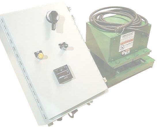
1 Knowledge Base Article Type: Instructions Remote Temperature Controller for Heated Mold Shoes, using a RTD/Digital Display, # C (version pre-2009). Description: Instructions on How to properly set-up and operate Remote Temperature Controller using a RTD/Digital Display; part # C. Three (3) control circuits 230 volt/each up to 20 amps (4KW), Total (12KW), single phase. Typically used on Models 22HF, and 16HF machines, and (2 and 3) block Pit Model machines. This controller version pre- February WARNING Never work on, clean or service this unit, control panel or any machine or open or remove any protective cover, guard, grate, door, or maintenance panel until the power or energy sources has been turned off, locked out / tagged out, and all moving parts have come to a complete stop and or blocked to prevent movement. Machinery is dangerous avoid personal injury and or death by following manufacture, Local, and OHSA safety procedures. Contact Columbia Machine for safety decals, guards, horns and beacons.

2


3 3-phase disconnect Heater failure indicator light Power on/off switch Digital temperature control display Remote temperature controller panel face
 (2 pole)")
4 5 amp circuit breaker (2 pole) 10 amp circuit breaker (1 pole) 3-phase disconnect Control transformer Relay Current transformer Limit alarm module 20 amp circuit breaker (3) (2 pole) Contactors (3)

5 Panel face Connecting cable Heated mold shoes
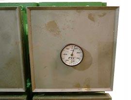
6 Magnetic thermometer
 Power circuit")
7 2-pole 20 amp circuit breakers (3) Contactors (3) Power circuit layout
 turn trim pot with a (10) turn top-mounted dial Both models")

8 Trim pots (4) MM1600 Red/green indicator lights (10) Turn top-mounted dial MM1604 Red/green indicator lights Model Specifications MM trim pots MM 1604 Replaces the (25) turn trim pot with a (10) turn top-mounted dial Both models come with zero and span calibrated trim pots at 0-50 mv. Adjust the set-point and deadband trim pots only. If the input range from the current transformer (C.T.) is set too low, the span trim pot may be adjusted counter-clockwise (CCW) for greater input swing.
9

10 Set-point selector switch Set I adjustment 3-digit display Output light Digital temperature control display Control or Indicator Set-point toggle switch Set I knob Output light Function Operators can display the set-point temperature on the 3-digit display by holding the set-point toggle switch to the right Operators can adjust the set-point temperature by holding the set-point toggle switch to the right while turning the Set I knob clockwise to increase the temperature setting and counter-clockwise to decrease the temperature setting The output light illuminates when the output circuitry is actuated to apply power to the system
11 Item Frequency Procedure Digital temperature controller Prior to use Clean and protect from dirt, oil, corrosion, and vibration Mold head-box Prior to use Tighten connections Control panel Monthly Inspect connections for positive contact Digital temperature controller Electrical connections Monthly Inspect connections Power cables/rtd cables As needed Replace when frayed or damaged Component Panel box Input voltage Output circuit current Main breaker Specifications 20 wide x 30" high x 8" deep 220 AC single phase 3 20 amp circuits, 4 kw/circuit 60 amp, 12 kw total
12 Symptom Probable Cause Check Corrective Action Mold shoes not heating No line voltage Verify 240 VAC Restore power voltage Open main breaker Check main breaker Close main breaker Open main circuit Check heater for shorting Close circuit breaker Power cable Check cable for cuts, damage, or tears; Check connector & plug Replace cable; tighten or replace connector & plug Terminal connections Failed heater Contactor not energized Digital temperature No line voltage controller is inactive. No output light or digital display. Digital temperature controller reads ambient temperature Defective power Output light not illuminated on digital temperature controller Digital temperature controller display reads negative numbers Heater failure indicator light on Check terminal connections inside mold head Check heater for open circuit Check 120 VAC voltage Check timer relay settings Check fuse Check power on/off selector switch Check circuit breaker Tighten terminals Replace heater Close 120 VAC circuit breaker Adjust T1 & T2 Replace fuse Turn switch on Defective heater Heater Replace heater Open heater Heater Replace heater Power cable Replace power cable cable Open RTD RTD Replace RTD Defective RTD cable RTD Check cable for cuts, damage, or tears Check connector and plug Check cable for proper wiring Replace cable Tighten or replace connector and plug Correct wiring Calibrate/setup See calibration Recalibrate section of manual Defective heater Heater Replace heater
13
14
15
Mixer Discharge Door Adjustment on models; 30, 42, 54, 81, 108, 135 mixers.
 Knowledge Base Article Type: Instructions Mixer Discharge Door Adjustment on models; 30, 42, 54, 81, 108, 135 mixers. Description: Instructions on How to set-up and adjust the discharge door on Columbia
Model 930 Power Control System Instruction Manual
 Model 930 Power Control System Instruction Manual Publication No. A105328-001 Rev A December 2000 Another quality product from: 7128 Shady Oak Rd, Eden Prairie MN 55344 Phone: (952) 949-9009 Fax: (952)
331-SV. User Manual THREE PHASE DUPLEX LIFT STATION CONTROL PANEL WITH STATIONVIEW CONTROLLER. Ashland, OH
 331-SV User Manual THREE PHASE DUPLEX LIFT STATION CONTROL PANEL WITH STATIONVIEW CONTROLLER Ashland, OH 800-363-5842 WWW.PRIMEXCONTROLS.COM Warranty void if panel is modified. Call factory with servicing
Cylinder Installation Compression/Stripper, for Models, 22HF, 16HF, 1600 machines
 Knowledge Base Article Type: Instructions Cylinder Installation Compression/Stripper, for Models, 22HF, 16HF, 1600 machines Description: Instructions on How to properly install stripper beam and compression
TS-E TURBO STEAM ELECTRIC COUNTERTOP CONVECTION STEAMER PARTS AND SERVICE MANUAL
 TS-E TURBO STEAM ELECTRIC COUNTERTOP CONVECTION STEAMER PARTS AND SERVICE MANUAL EFFECTIVE JUNE 12, 2017 Superseding All Previous Parts Lists. The Company reserves the right to make substitution in the
Heat Tracing Sales Mt. Airy, Maryland Controls
 Heat Tracing Line Sensing Control Panels Solid State Relay Output Rated 30 Amps or Two-Pole Contactor Control Output Universal Inputs NEMA 4/4X Enclosure Ground Fault Alarm/Trip Monitor or GFI Circuit
B BASIC HEAT TREATMENT CONSOLE
 Maritime Stress PO Box 2898, 30 Estates Road Dartmouth, NS, B2W 4Y2, Canada Toll Free: 1-877-468-1781 Phone: (902) 468-7873 Fax: (902) 468-2304 Website: E-mail: info@maritimestress.com OPERATION MANUAL
SCR Power Controllers
 SCR Power Controllers Instruction Manual SCR POWER CONTROLLERS TABLE OF CONTENTS General Description and Specifications...1 Firing Modes....2 Installation and Wiring...4 Operation...9 Troubleshooting...15
SOLAR-150HD. 150-Watt Dual Halogen Illuminator. Service Manual Bowdendale Avenue Jacksonville, FL 32216
 SOLAR-150HD 150-Watt Dual Halogen Illuminator Service Manual 6018 Bowdendale Avenue Jacksonville, FL 32216 Customer Service: 904 731-5869 FAX 904 733 0012 Toll Free 800-684-6404 TABLE OF CONTENTS Page
Basics of Control Components
 Basics of Control Components Table of Contents Introduction...2 Electrical Symbols...6 Line Diagrams...16 Overload Protection...22 Overload Relays...26 Manual Control...35 Magnetic Contactors and Starters...41
The Temperature Control Company SERIES 2000 / 3020 ANALOG TEMPERATURE CONTROLLERS. Instruction Manual
 The Temperature Control Company SERIES 2000 / 3020 ANALOG TEMPERATURE CONTROLLERS Instruction Manual Introduction Congratulations on your purchase of an Athena Series 2000 or Series 3020 analog temperature
T21 Thermal Differential Switch
 T21 Thermal Differential Switch General Instructions The T21 Point Level Switch is a state-of-the-art in liquid level and interface measurement and control. Level detection is accomplished by using a high-resolution
IM K IM K. Instructions for Cutler-Hammer Jockey Pump Controllers
 IM05805004K IM05805004K Instructions for Cutler-Hammer Jockey Pump Controllers IM05805004K Page i TABLE OF CONTENTS 1. INSTALLATION AND MOUNTING OF THE CONTROLLER... 1 2. SYSTEM PRESSURE CONNECTIONS...
Accessory 44 Strip Heater. Automatic Transfer Switches. Wiring. Mounting H
 Accessory 44 Strip Heater for Automatic Transfer Switches Accessory 44 Strip Heater is designed to keep humidity and/or temperature within the ATS enclosure at acceptable levels. This accessory consists
Fincor Series 2230 MKII/2240
 Fincor Series 2230 MKII/ Fincor Series 2200 regenerative drives are ideal for your more demanding applications. They feature flexibility with ratings up to 5 horsepower. The Series 2230 MKII offers new
th Street, Surrey, B.C. Canada V3W 0A6 Telephone Fax July 2012
 8238-129 th Street, Surrey, B.C. Canada V3W 0A6 Telephone 604-572-3935 Fax 604-590-8313 http://www.kobelt.com 7173-KAS MANUAL July 2012 Leaders in Quality Marine Controls, Steering Gear, and Disc Brakes.
PARTS & SERVICE MANUAL
 PARTS & SERVICE MANUAL Impinger Low Profile Advantage Digital Series (Electric) International Models MODELS: Please note that the model numbering system changed March 2007. The chart below shows the old
Reproduction or other use of this Manual, without the express written consent of Vulcan, is prohibited.
 SERVICE MANUAL ELECTRIC BRAISING PANS (30 & 40 GALLON) VE30 VE40 ML-126849 ML-126850 VE40 SHOWN - NOTICE - This Manual is prepared for the use of trained Vulcan Service Technicians and should not be used
Phenix Technologies Inc. 75 Speicher Drive Accident, Maryland 21520
 USER S MANUAL PORTABLE HIGH CURRENT TEST SET MODEL NUMBER HC2 Version 4.0 Phenix Technologies Inc. 75 Speicher Drive Accident, Maryland 21520 Copyright Phenix Technologies, Inc. Rev 11/20/2014 nab TABLE
February, O & M Manual for EATON FDJ Series Jockey Pump Controllers. Instruction Booklet. For more information visit:
 February, 2009 O & M Manual for EATON FDJ Series Page 2 TABLE OF CONTENTS 1. INSTALLATION AND MOUNTING OF THE CONTROLLER...3 2. SYSTEM PRESSURE CONNECTIONS...3 3. ELECTRICAL CONNECTIONS...3 3.1 ELECTRICAL
BIGLA30-T/BIELA14-T Event Codes Quick Reference EXPLANATION CORRECTIVE ACTION PARTS TO CARRY ON SERVICE CALL
 E13 TEMPERATURE PROBE FAILURE E16 HIGH LIMIT 1 EXCEEDED A. TEMP Probe reading out of range. B. Bad Connection. C. Problem with the temperatur e measuring circuitry including the probe. High limit temperature
PARTS LIST, COUNTER CONVECTION STEAMERS MODELS SN-3E, SN-4E, SN-5E PARTS LIST COUNTER CONVECTION STEAMERS BLODGETT MODELS: SN-3E SN-4E
 PARTS LIST COUNTER CONVECTION STEAMERS BLODGETT MODELS: SN-3E SN-4E November 27, 2013 BLODGETT OVEN CO 44 lakeside Ave Burlington, VT 05446 Tel. 802-658-6600 Fax 802-860-3732 www.blodgett.com 1 2013-11-27
Quick Start Guide TS 910 & TS 920
 Quick Start Guide TS 910 & TS 920 DANGER HAZARD OF ELECTRICAL SHOCK, EXPLOSION, OR ARC FLASH Read and understand this quick start guide before installing and operating the transfer switch The installer
MD10. Engine Controller. Installation and User Manual for the MD10 Engine Controller. Full Version
 MD10 Engine Controller Installation and User Manual for the MD10 Engine Controller. Full Version File: MartinMD10rev1.4.doc May 16, 2002 2 READ MANUAL BEFORE INSTALLING UNIT Receipt of shipment and warranty
2. AC SERVICE AND MOTOR REQUIRED 1. ENCLOSURE REQUIRED
 1. ENCLOSURE REQUIRED If the OC1 control is furnished as an open-chassis unit (standard), mount control in an enclosure 12 x 10 x 5 or larger and mount enclosure where room temperature does not exceed
INSTALLATION & OPERATION MANUAL. Fan Powered Terminals VAV TERMINALS. Redefine your comfort zone.
 INSTALLATION & OPERATION MANUAL Fan Powered Terminals VAV TERMINALS IOM FAN POWERED TERMINALS Receiving Inspection After unpacking the terminal, check it for shipping damage. If any shipping damage is
Filtered PWM Speed Control for Permanent Magnet DC Motors
 Instructions for Installation and Operation Filtered PWM Speed Control for Permanent Magnet DC Motors Model 0794 Speed and Direction Control up to 5/8 HP NEMA-1/IP-20 Specifications Product Type:... WPM-2148E1
DC3R Regenerative DC Drive User Guide 1/4 to 2 HP, 115/230 VAC
 DC3R Regenerative DC Drive User Guide 1/4 to 2 HP, 115/230 VAC Instruction Manual D2-3453 The information in this manual is subject to change without notice. Throughout this manual, the following notes
Variable Regulated Voltage Power Supply Instruction Manual Model XP-605 / XP-752A
 Variable Regulated Voltage Power Supply Instruction Manual Model XP-605 / XP-752A Copyright Elenco Electronics, Inc. REV-D DC POWER SUPPLY 1 2 4 5 CURRENT VOLTAGE 13 3 6 C.C. C.V. 7 FINE COARSE FINE COARSE
R800-16PCPS DUAL REDUNDANT POWER SUPPLY FOR THE R RACK USER MANUAL
 R800-16PCPS Manual 1 R800-16PCPS DUAL REDUNDANT POWER SUPPLY FOR THE R800-16 RACK USER MANUAL R800-16PCPS Manual 2 R800-16PCPS DUAL REDUNDANT POWER SUPPLY USER S MANUAL DRAWING # A00728 Rev. A GDI Communications,
17429X.00 SERIES MODELS:
 LEESON ELECTRIC MOTORS, GEARMOTORS AND DRIVES R User s Manual 17429X.00 SERIES MODELS: 174298.00 174299.00 PWM REGENERATIVE DC TO DC DRIVES II Table of Contents 17429X.00 Drives...............................................................
ETP-5E & ETP-10E ECO-TECH PLUS ELECTRIC CONVECTION STEAMER PARTS AND SERVICE MANUAL
 ETP-5E & ETP-10E ECO-TECH PLUS ELECTRIC CONVECTION STEAMER PARTS AND SERVICE MANUAL EFFECTIVE JANUARY 10, 2018 Superseding All Previous Parts Lists. The Company reserves the right to make substitution
Quick Start Guide TS 910
 Quick Start Guide TS 910 DANGER HAZARD OF ELECTRICAL SHOCK, EXPLOSION, OR ARC FLASH Read and understand this quick start guide before installing and operating the transfer switch The installer is responsible
R81EAA-2 Economizer Circuit Board
 FAN 121, 628.1 Motor Actuators Section M Technical Bulletin R81E Issue Date 0993 R81EAA-2 Economizer Circuit Board Applications Setpoint Adjustment Temp T1 T2 S2 1O S 1 8 9 Changeover Relay Refrigeration
OPERATIONS AND APPLICATIONS MANUAL MODEL NUMBER PM6. 6 KV DC HIGH POTENTIAL TESTER WITH MEGOHMMETER Version 2.0
 OPERATIONS AND APPLICATIONS MANUAL MODEL NUMBER PM6 6 KV DC HIGH POTENTIAL TESTER WITH MEGOHMMETER Version 2.0 TABLE OF CONTENTS Section Number DANGER PRODUCT INFORMATION 1 -SAFETY AND CAUTION NOTES -DESCRIPTION
MODEL 520 REMOTE START ENGINE MANAGEMENT SYSTEM
 MODEL 520 REMOTE START ENGINE MANAGEMENT SYSTEM DSE 520 ISSUE 4 4/4/02 MR 1 TABLE OF CONTENTS Section Page INTRODUCTION... 4 CLARIFICATION OF NOTATION USED WITHIN THIS PUBLICATION.... 4 1. OPERATION...
POWER SUPPLY MODEL XP-800. TWO AC VARIABLE VOLTAGES; 0-120V and 7A, PLUS UP TO 10A. Instruction Manual. Elenco Electronics, Inc.
 POWER SUPPLY MODEL XP-800 TWO AC VARIABLE VOLTAGES; 0-120V and 0-40V @ 7A, PLUS 0-28VDC @ UP TO 10A Instruction Manual Elenco Electronics, Inc. Copyright 1991 Elenco Electronics, Inc. Revised 2002 REV-I
1-3 MANUAL STARTERS EXERCISE OBJECTIVE. Examine and describe the operation of manual motor starters. DISCUSSION
 1-3 MANUAL STARTERS EXERCISE OBJECTIVE Examine and describe the operation of manual motor starters. DISCUSSION Motor starters are made out of power switches and overload protection devices. They can be
Types of Motor Starters There are several types of motor starters. However, the two most basic types of these electrical devices are:
 Introduction Motor starters are one of the major inventions for motor control applications. As the name suggests, a starter is an electrical device which controls the electrical power for starting a motor.
Arch HTH Water Chemicals Commercial Equipment Trouble Shooting Guide
 Arch HTH Water Chemicals Commercial Equipment Trouble Shooting Guide 8/28/00 TROUBLESHOOTER S GUIDE PROBLEM CAUSE SOLUTION Insufficient water flow to chlorinator Check water flow through Flow Controller
FC/FCA 12, 24, 32 & 48 VOLT, 6 & 10 AMP BATTERY CHARGER OPERATION & MAINTENANCE GUIDE
 FC/FCA 12, 24, 32 & 48 VOLT, 6 & 10 AMP BATTERY CHARGER OPERATION & MAINTENANCE GUIDE SENS part number: 101037 Document revision: A Engineering change number: 105073 Date: 1/13/2006 1840 Industrial Circle
OnCommand Troubleshooting Guide Hayward Industries
 OnCommand Troubleshooting Guide 2010 Hayward Industries Table of Contents Safety Precautions Page 1 Overview Pages 2-5 Software Troubleshooting Page 6 Local Display Pages 7-8 Relays Pages 9-10 Heaters
OPERATIONS MAINTENANCE MANUAL
 OPERATIONS MAINTENANCE MANUAL COOK & HOLD OVEN SYSTEMS COMMERCIAL & INSTITUTIONAL SERIES WITTCO MODEL NUMBERS 750-AD-SS 1000-AD-SS 1200-AD-SS 1400-AD-SS 750-AD-SS-IS 1000-AD-SS-IS 1200-AD-SS-IS 1400-AD-SS-IS
GE Sensing & Inspection Technologies
 GE Sensing & Inspection Technologies Modus Model RPM-1 Room Pressure Monitor Installation and Setup Guide 1. GENERAL The RPM-1 monitors either positive or negative room pressures (see the Datasheet for
DFC-1 STANDARD TEMPERATURE CONTROL. DFC-2 TEMPERATURE CONTROL w/ INTEGRAL 40 F-90 F SELECTOR DFTD TEMPERATURE SELECTION DIAL DFTS TEMPERATURE SENSOR
 24 Volt AC input Built in 15 second low fire start timer 0-24 Volt DC modulating output Remote temperature selection Calibration trim pot Rated for -40 F (-40 C) DFC-1 STANDARD TEMPERATURE CONTROL DFC-2
POWER DOOR LOCKS 8P - 1 POWER DOOR LOCKS CONTENTS
 PL POWER DOOR LOCKS 8P - 1 POWER DOOR LOCKS CONTENTS POWER DOOR LOCKS... 1 REMOTE KEYLESS ENTRY... 3 POWER DOOR LOCKS INDEX INTRODUCTION... 1 DOOR LOCK MOTOR... 1 DOOR LOCK SWITCH... 1 INTRODUCTION All
Type SOQ Negative Sequence Time Overcurrent Relay
 ABB Power T&D Company Inc. Power Automation & Protection Division Coral Springs, FL Allentown, PA April 1998 Supersedes DB dated August 1991 Mailed to: E,D, C/41-100B For Protection of Rotating Machinery
MANUAL ELECTRIC FIRE PUMP CONTROLLERS METRON SERIES MV600
 MANUAL ELECTRIC FIRE PUMP CONTROLLERS METRON SERIES MV600 TABLE OF CONTENTS PART I GENERAL DESCRIPTION... PAGE 2 PART II FUNCTIONS... PAGE 2 PART III INSTALLATION... PAGE 3 PART IV INITIAL INSTALLATION
KENCO ENGINEERING COMPANY
 KENCO ENGINEERING COMPANY P.O. BOX 470426 TULSA, OK 74147-0426 PHONE: (918) 663-4406 FAX: (918) 663-4480 www.kenco-eng.com e-mail: info@kenco-eng.com SERIES KTD THERMAL DIFFERENTIAL FLOW/LEVEL SWITCH INSTALLATION
12 Series Linear Actuators. Operation & Maintenance Manual, Analog Positioner Installation
 12 Series Linear Actuators Operation & Maintenance Manual, Analog Positioner Installation 6810 POWERLINE DR.-FLORENCE, KY. 41042 - TELEPHONE 859-727-7890, TOLL FREE 1-800-662-9424 FAX. 859-727-4070, E-MAIL:
ES52 Auto Start Engine Controller Installation and User Manual for the ES52 Auto Start Engine Controller.
 ES52 Auto Start Engine Controller Installation and User Manual for the ES52 Auto Start Engine Controller. Full Version File: ES52rev2.63.doc October 24, 2006 2 Thank You For Purchasing This DynaGen Product
Electric Modulating Actuator Installation, Operation & Maintenance Manual
 Electric Modulating Actuator Installation, Operation & Maintenance Manual For Use with: All Modulating AC Voltage Models Additional supplements may be needed for selected optional equipment including,
OPERATION MANUAL. TZ Two Zone Controller
 Maritime Stress PO Box 2898, 30 Estates Road Dartmouth, NS, B2W 4Y2, Canada Toll Free: 1-877-468-1781 Phone: (902) 468-7873 Fax: (902) 468-2304 Website: E-mail: info@maritimestress.com OPERATION MANUAL
A. Products shall be designed, manufactured, tested, and installed in compliance with the following standards:
 SECTION 26 29 13 ENCLOSED MOTOR CONTROLLERS PART 1 - GENERAL 1.1 RELATED DOCUMENTS: A. The Conditions of the Contract and applicable requirements of Divisions 0 and 1 and Section 26 00 01, Electrical General
Controls and Instruments
 CHAPTER 9 Controls and Instruments A complex set of controls and instruments monitors the operation of an electric generator set. Equipment operators must understand what these controls and instruments
HLS Watt Halogen Illuminator Service Manual
 HLS-150 150-Watt Halogen Illuminator Service Manual 6018 Bowdendale Avenue Jacksonville, FL 32216 Customer Service: 904 737 7611 FAX 904 733 4832 Toll Free 877 677 2832 (English) TABLE OF CONTENTS Page
PARTS-WIRING TECHNICAL MANUAL MSHA PERMISSABLE CONTROLS CB-801 CB-8218
 PARTS-WIRING TECHNICAL MANUAL MSHA PERMISSABLE CONTROLS CB-80 CB-88 TABLE OF CONTENTS TABLE OF CONTENTS... SAFETY WARNING!... 3 EXPLOSION PROOF ELECTRICAL EQUIPMENT - HAZARD WARNINGS... 4 STANCOR PERMISSIBLE
DIN Rail UPS Model: DIN-UPS Installation/Operation Manual
 DIN Rail UPS Model: DIN-UPS 24-10 Installation/Operation Manual Table of Contents Section Page Section Page Quick Start 2 1) General Information 4 Materials Provided 4 Optional Equipment 4 2) Safety Information
SERVICE MANUAL IMPINGER COUNTERTOP OVEN MODEL 1300 SERIES
 SERVICE MANUAL IMPINGER COUNTERTOP OVEN MODEL 1300 SERIES Lincoln Foodservice Products, LLC 1111 North Hadley Road Fort Wayne, Indiana 46804 United States of America Phone : (800) 374-3004 U.S. Fax: (888)
J1 Plug Pin Identification
 D D8 D D D D ART_8 J 8 D D0 R R R R TB 80 D D D D D D J Plug Pin Identification PIN # WIRE # SIGNAL FUNCTION 0 INPUT Drive Reverse INPUT Drive Forward OUTPUT Brake, Decel Valve signal 8 INPUT Steer Left
1/4HP - 7.5HP 120/240/277 VOLTS 50/60HZ
 Installation & Operating Procedures DG2 Series SINGLE PHASE CONVERTERS 1/4HP - 7.5HP 120/240/277 VOLTS 50/60HZ TABLE OF CONTENTS 1.0 DESCRIPTION... Pg. 1 2.0 INSTALLATION AND START-UP... Pg. 3 3.0 DRAWING
J.E. ADAMS INDUSTRIES OWNERS MANUAL VACUUMS AIR/VACUUMS AIR/WATER/VACUUMS
 J.E. ADAMS INDUSTRIES OWNERS MANUAL AIR/ AIR/WATER/ PAGE 1-3 SPECIFICATIONS PAGE 4-6 INSTALLATION PAGE 7-10 WIRE DIAGRAMS PAGE 11 TIMER INFORMATION PAGE 12-16 DRAWINGS & PART NUMBERS PAGE 17 TROUBLESHOOTING
A1P OPERATING MANUAL
 A1P OPERATING MANUAL TABLE OF CONTENTS Introduction... p. 2 Features... p. 2 Description... p. 3 Theory of Operation... p. 3 Installation... p. 4 Electrical Connections... p. 5 Options... p. 6 Warranty...
Exercise 1-3. Manual Starters EXERCISE OBJECTIVE DISCUSSION OUTLINE DISCUSSION. Direct-on-line (DOL) starters. Reversing starters
 starters. Reversing starters") Exercise 1-3 Manual Starters EXERCISE OBJECTIVE Examine and describe the operation of manual motor starters. DISCUSSION OUTLINE The Discussion of this exercise covers the following points: Direct-on-line
Exercise 1-3 Manual Starters EXERCISE OBJECTIVE Examine and describe the operation of manual motor starters. DISCUSSION OUTLINE The Discussion of this exercise covers the following points: Direct-on-line
Calibration and Performance Check: Agilent Dual Plasma Controller
 Calibration and Performance Check: Agilent Dual Plasma Controller Purpose Outline the steps used to calibrate and verify the performance of the Agilent Technologies Dual Plasma Controller. Scope This procedure
AUTOMATIC 12 WAY HEAT TREATMENT CONSOLE
 Maritime Stress PO Box 2898, 30 Estates Road Dartmouth, NS, B2W 4Y2, Canada Toll Free: 1-877-468-1781 Phone: (902) 468-7873 Fax: (902) 468-2304 Website: E-mail: info@maritimestress.com OPERATION MANUAL
PRODUCT / TEST MANUAL 2C58K2 INSTANTANEOUS OVERCURRENT
 Sheet 1 of 6 Order Number Serial Number PRODUCT / TEST MANUAL 2C58K2 INSTANTANEOUS OVERCURRENT Issue Date Level A 22/10/02 Initial issue. Summary of changes Due to RMS continuous product improvement policy
BLDC SPEED CONTROL INSTRUCTION MANUAL Line voltage Brushless DC control
 BLDC SPEED CONTROL INSTRUCTION MANUAL Line voltage Brushless DC control Phone 712.722.4135 groschopp.com 420 15th St NE, Sioux Center, IA 51250 Toll-Free 800.829.4135 Email sales@groschopp.com FAX 712.722.1445
Outdoor Enclosure Power System ENC X100MP48F20-AC6
 Outdoor Enclosure Power System ENC673034-1X100MP48F20-AC6 Manual MA015151A4 Issue 1 Nov 2010 Copyright 2010 Myers Power Products, Inc. Part# A015151A4 MA015151A4 Iss1 Page 1 of 24 Dimensions Outdoor Enclosure
DCT SERIES CASE SIZE 3A FILTERED BATTERY CHARGER 12V/200A 24V/ A 48V/100A 120V/50A 240V/25A OPERATION & MAINTENANCE GUIDE
 DCT SERIES CASE SIZE 3A FILTERED BATTERY CHARGER 12V/200A 24V/150-200A 48V/100A 120V/50A 240V/25A OPERATION & MAINTENANCE GUIDE SENS part number: 101137-3 Document revision: B DCN number: 105286 Date:
Table of Contents. For latest version, visit:
 Table of Contents 1.0 Introduction... 1.0 Overview... 1 3.0 Test Set Controls... 6 3.1 Power... 6 3. Time Display... 6 3.3 Timer Clear Push Button... 6 3.4 Start Push Button and LED... 6 3.5 Stop Push
ECU-02 Ver2.1 Automatic Engine Control Unit Operators Manual
 ECU-02 Ver2.1 Automatic Engine Control Unit Operators Manual Headquarters : No.3, Lane 201, Chien Fu St., Chyan Jenn Dist., Kaohsiung, TAIWAN Tel : + 886-7-8121771 Fax : + 886-7-8121775 URL : http://www.kutai.com.tw
SECTION MOTOR CONTROL
 SECTION 26 24 19 MOTOR CONTROL PART 1 - GENERAL 1.1 SECTION INCLUDES A. Manual motor starters B. Magnetic motor starters C. Combination magnetic motor starters D. Solid-state reduced voltage motor starters
Boston Gear Ratiotrol DC Motor Speed Control
 Boston Gear Ratiotrol DC Motor Speed Control P-3049-BG Doc. No. 83721 Installation and Operation RG1 and RG2 Models 1/6-1 HP a division of Altra Industrial Motion Contents General Information.....................
J1 Plug Pin Identification
 D5 D8 D7 D4 D5 D ART_8 J 4 8 D D0 7 R R R R4 TB 80 D D D D4 D D J Plug Pin Identification PIN # WIRE # SIGNAL FUNCTION 0 INPUT Drive Reverse INPUT Drive Forward OUTPUT Brake, Decel Valve signal 4 8 INPUT
DIN Rail UPS DC UPS/Battery Detection System Model: BDS-DIN-UPS Installation/Operation Manual
 DIN Rail UPS DC UPS/Battery Detection System Model: BDS-DIN-UPS 24-10 Installation/Operation Manual Table of Contents Section Page Section Page Quick Start 2 1) General Information 4 Materials Provided
MAINTENANCE INFORMATION ====================
 CHAPTER 1 MAINTENANCE INFORMATION ==================== C O N T E N T S TEST EQUIPMENT REQUIRED SECTION 1 Page 3 FAULT FINDING & SERVICING NOTES SECTION 2 Page 3 VOLTAGE CHECKS WITH NO VALVE UNDER TEST
RP-4000 Reserve Power Control
 Instruction Manual IM-0580 RP-4000 Reserve Power Control Table of Contents General Information... 2-3 Introduction... 2 Cautions... 2 Receiving/Inspection... 2 Storage... 2 Equipment Return... 2 Identification
BC141, BC142, BC142-5 & BC142-6 DC Control
 BC141, BC142, BC142-5 & BC142-6 DC Control 5/17 Installation & Operating Manual MN704 Any trademarks used in this manual are the property of their respective owners. Important: Be sure to check www.baldor.com
Euclid Full Voltage Magnet Controller
 Hubbell Industrial Controls, Inc. Euclid Full Voltage Magnet Controller Instruction & Renewal Parts Manual Instructions/Parts Manual Publication No. 180 Replaces Sept. 1991 4291 & 4295/ 96 Type 4291 Type
715B CONTROL SERIES. Instruction Manual Line Voltage DC Brushless Motor Control CONTROLS. Phone (317) Fax (317)
 Fax (317)") 715B CONTROL SERIES CONTROLS Instruction Manual Line Voltage DC Brushless Motor Control LT715B (IM-715B-0100) P.O. Box 10 5000 W. 106th Street Zionsville, Indiana 46077 Phone (317) 873-5211 Fax (317) 873-1105
715B CONTROL SERIES CONTROLS Instruction Manual Line Voltage DC Brushless Motor Control LT715B (IM-715B-0100) P.O. Box 10 5000 W. 106th Street Zionsville, Indiana 46077 Phone (317) 873-5211 Fax (317) 873-1105
TROUBLESHOOTING GUIDE FOR HEAT PUMP BOOSTERS MODELS: HPB11, HPB15, & HPB22
 V3 TROUBLESHOOTING GUIDE FOR HEAT PUMP BOOSTERS MODELS: HPB11, HPB15, & HPB22 PREFACE This guide contains instructions for troubleshooting the Steffes Corporation room heating units: Models HPB 11, HPB
Ultrafryer Low Oil Level Model E3RL-14/8 Operation Instructions for Remote U-23 with Auxiliary Controls
 Ultrafryer Low Oil Level Model E3RL-14/8 Operation Instructions for Remote U-23 with Auxiliary Controls PN 30A245 rev A TABLE OF CONTENTS Page Preface 3 Recommended Spare Parts 4 Fryer Specifications 5
GENERAL <ELECTRICAL>
 00E-1 GROUP 00E GENERAL CONTENTS HARNESS CONNECTOR INSPECTION................................. 00E-2............. 00E-6................. 00E-6 TROUBLESHOOTING STEPS.......... 00E-6 INFORMATION
AF-17 Electronic Positioner Installation, Operation and Maintenance Instructions
 WCAIM2031 AF-17 Electronic Positioner Installation, Operation and Maintenance Instructions MODELS 20 For AF-17 Boards Mounted Inside 10-23 75 Actuator. 30 For AF-17 Boards Mounted Inside 25-30 75 Actuator.
MODEL RMS INSTALLATION INSTRUCTIONS. CONTENTS Page A. Introduction 1. Usage 2 2. How it operates 2
 CONVEYOR COMPONENTS COMPANY Division of Material Control, Inc. 130 Seltzer Road, PO Box 167 Croswell, MI 48422 USA PHONE: (810) 679-4211 TOLL FREE (800) 233-3233 FAX: (810) 679-4510 Email: info@conveyorcomponents.com
Northwest RV Supply Manual Compliments of Printed From TROUBLESHOOTING
 TROUBLESHOOTING for the 5 BUTTON 3109228.001 COMFORT CONTROL CENTER SYSTEM INTRODUCTION The Comfort Control Center control system can be used to operate the following Duo-Therm Units: Roof Top Air Conditioners
OIL FIELD ELECTRIC ACTUATOR INSTRUCTION MANUAL SPECIAL APPLICATIONS ACTUATORS Q 6.0.1
 OIL FIELD ELECTRIC ACTUATOR INSTRUCTION MANUAL SPECIAL APPLICATIONS ACTUATORS Q 6.0.1 This instruction manual contains important information regarding the installation, operation, and troubleshooting of
Continuing Education Course #206 Introduction to Designing Machine Control Systems Part 2
 1 of 5 Continuing Education Course #206 Introduction to Designing Machine Control Systems Part 2 1. Continuing to answer the following questions indicates that you understands that the presented material
SHORT-STOP. Electronic Motor Brake Type G. Instructions and Setup Manual
 Electronic Motor Brake Type G Instructions and Setup Manual Table of Contents Table of Contents Electronic Motor Brake Type G... 1 1. INTRODUCTION... 2 2. DESCRIPTION AND APPLICATIONS... 2 3. SAFETY NOTES...
ELECTRIC SCHEMATICS LS1 LS2. "1532ES / 1932ES" Service & Parts Manual - ANSI Specifications March 2008 Page 5-9 ART_2236 ART_2243
 ELECTRIC SCHEMATICS NOTES: (Unless otherwise specified). Switch S BASE/PLATFORM makes contact from the CENTER to the LEFT position when placed in BASE.. Switch S UP/DOWN makes contact from the CENTER to
12 Series Linear Electric Actuator Installation, Operation & Maintenance Manual
 12 Series Linear Electric Actuator Installation, Operation & Maintenance Manual TELEPHONE: +1-859-727-7890 TOLL FREE: +1-800-662-9424 FAX: +1-859-727-4070 E-MAIL: DVOGES@INDELAC.COM MROBINSON@INDELAC.COM
A6Z OPERATING MANUAL
 A6Z OPERATING MANUAL TABLE OF CONTENTS Introduction... p. 2 Features... p. 2 Description... p. 3 Theory of Operation... p. 3 Installation... p. 4 Electrical Connections... p. 5 Options... p. 6 Warranty.p.
PIECAL 322 Automated Thermocouple Calibrator Operating Instructions. Product Description
 PIECAL 322 Automated Thermocouple Calibrator Operating Instructions Product Description Easy to use With the PIECAL 322-1 you can check & calibrate all your thermocouple instruments and measure thermocouple
650 Series Cargo Van Lift Mounting Instructions Fullsize Ford 1992-Present
 TOMMY GATE OWNER'S / OPERATOR'S MANUAL 650 Series 650 LB Capacity 650 Series Cargo Van Lift Mounting Instructions Fullsize Ford 1992-Present Installing the Base Plate 1. Examine the interior and exterior
Instruction Bulletin. Jockey Pump Controller
 Instruction Bulletin Jockey Pump Controller Installation Start Up Service This instruction bulletin is a guide for personnel involved with maintenance, engineering and approval of Fire Pump equipment and
Rated for use on 110/120VAC 60Hz and 220/240VAC 60Hz applications
 WPC1-XXXX-T Rated for use on 110/120VAC 60Hz and 220/240VAC 60Hz applications Installation Instructions: Read these instructions in their entirety before performing any installation work. FOR USE WITH
Troubleshooting Bosch Proportional Valves
 Troubleshooting Bosch Proportional Valves An Informative Webinar Developed by GPM Hydraulic Consulting, Inc. Instructed By Copyright, 2009 GPM Hydraulic Consulting, Inc. TABLE OF CONTENTS Bosch Valves
OWNER S MANUAL MODEL: PT 450 / PT 450M WELDING POSITIONER
 OWNER S MANUAL RD-8450E Important Read these instructions before installing, operating or servicing this product. MODEL: PT 450 / PT 450M WELDING POSITIONER Serial number 1506003 ~ and later Revised date
Boston Gear Ratiotrol
 Boston Gear Ratiotrol DC Motor Speed Control Installation and Operation Doc. No. 3721 RG1 and RG2 Models 1/6-1 HP GENERAL INFORMATION DESCRIPTION Series RG Controllers statically convert single-phase AC