Which one? All are capable of doing the job
|
|
|
- Lilian Horton
- 5 years ago
- Views:
Transcription
1 TM

2 Which one? All are capable of doing the job Now is the time to get it off the shelf and get acquainted with it. The LVCT can make you a topnotch vehicle electrical troubleshooter It s a well known fact that over half of the charging system components turned in for replacement are good! This means the LVCT is not being used You can use any model LVCT to test a vehicle battery, starting, or charging system. The tests will pinpoint your electrical trouble and put an end to unnecessary removal and turn-in of good parts Read and heed all notes pertaining to your LVCT
3 Topic TABLE OF CONTENTS Page Test Setup Identification Procedure LVCT Master Panel Identification List Allen Electrical and Equipment Co, Model Electro Mechanisms Corp, Model Ram Meter, lnc, Model 62F Auto Test, lnc, Model and Atomic Engineering, Model TV Heyer Products Co, Model Sun Electric Corp, Model LVR-3A Austin Continental Industries, lnc, Model 1060A Ram Meter, lnc, Model 70G Meter Test Leads and Cables Alternate Electrical Adapters Test Adapters Not Used for Generator/Regulator Tests Reading the Multiscale Meters Wheeled Vehicle Tests Precautionary Notes Battery Electrolyte Specific Gravity Test Battery System Load Test
4 Topic TABLE OF CONTENTS-Continued Page Individual Battery Test Starter Amperage Draw Test Starter Voltage Test Starter System Cable and Connection High Resistance Tests Generator Output Test Voltage Regulator Unit-Open Circuit Method-Test Voltage Regulator Unit-Fixed Resistor Method-Test Regulator Cutout Relay Test Current Regulator Unit Test Charging Circuit insulated Cable Test Charging Circuit Ground Loss (Resistance) Test Alternator Charging System 60 Amp AC Alternator Output Test # Alternator Output Test # Alternator Load Test Alternator to Battery Cable Test Alternator Ground Cable Test Rectifier Leakage Integrity) Test Sensing lnput (lntegrity) Test
5 Here s the set up: Each model LVCT in the organizational tool sets is shown and identified by manufacturer and model number. Identical connections and controls are identified by identical key numbers on illustrations and in text Although all LVCT s are capable of doing the same job, they are not physically alike. The display panels differ in type and arrangement of links, meters, posts, and switches. Electrical circuits in the LVCT s are not identical! This is why all items do not appear on all testers. The LVCT Master Panel identification List (page 5) identifies each item 3
6 The respective LVCT cables and Each electrical test adapter is test leads are also listed and iden- also listed and identified (pages 16, tified with a specific number (pages 17, & 18 First find your model on the following pages. Using masking tape, mark each link, meter, post, and switch so it wili correspond by number to the illustration and Master Panel Identification List Next, go to the cable and test leads and electrical test adapters. Tape and mark each item with its identifying numbers 4
7 LVCT MASTER PANEL IDENTIFICATION LIST 1 - Ammeter 2 - Load Bank Switch 3 - Voltmeter Selector Switch 4 - Voltmeter 5 - Voltmeter Positive Post 6 - Voltmeter Negative Post 7 - Field Rheostat Control Knob 8 - Field Rheostat Posts 1 & ¼-Ohm Resistor Posts 1 & Load Bank Control, Fine 11 - Load Bank 6-Volt Post 12 - Load Bank 12-Volt Post Load Bank 24-Volt Post Load Bank Common Post Ammeter Common Post Ammeter -100 Amp Post Ammeter -50 Amp Post Ammeter -10 Amp Post Load Bank Link, 12-Volt Load Bank Control, Coarse External Shunt Disconnect Link External Shunt Negative Post External Shunt Positive Post 5
8 ALLEN ELECTRIC AND EQUIPMENT CO model Close for 12v only 21-Open for ext shunt only No #11 post 6
9 ELECTRO MECHANISMS CORP model 1060 No #19 or #21 links 7
10 RAM METER INC model 62F For 6-volt operation, close 6V link 12 - For 12-volt operation, close 12v link 13 - For 24-volt operation, turn load bank coarse knob 20 to position 1. Position 1 has no control during 6-or 12-volt operation No #21 link 8
11 AUTO TEST INC model & ATOMIC ENGINEERING model TV 100 *LOAD BANK CONNECTIONS 11, 12, 13 Hook red ammeter lead C3 to post that pertains to the output of the circuit being tested, Common post is #14 No #10 post, #19 or #21 link 9
12 10
13 SUN ELECTRIC CORP model LVR-3A *2 - LOAD BANK SWITCH Load bank is turned off when arrow points to OFF (fully counterclockwise) **NO SELECTOR SWlTCH #3 USE APPLICABLE POST #6 No #10 post, #19 or #21 link 11
14 AUSTIN CONTINENTAL INDUSTRIES INC model 1060A *20-LOAD BANK CONTROLS A - 6-volt contact control B - 12-volt contact control C - 24-volt contact control 12 When using the load bank 1. Turn 6-volt control fully clockwise 2. To increase load, turn 12-volt control clockwise 3. For a further increase, turn the 24-volt control clockwise 4. If further adjustment is needed to get your voltage or amperage measurement, adjust with 10-ohm load bank control 10 No #19 and #21 links
15 RAM METER INC model 70G For 6-volt operation, close 6V link - For 12-volt operation, close 12v link 13 - For 24-volt operation, turn load bank coarse control 20 to position 1 *14 - Open link when using external shunt or ammeter and load bank separately When using load bank only, open link and use 14B When using ammeter only, open link and use 14A No #9 post 13

16 14 C1 - Voltmeter Positive Lead C2 - Voltmeter Negative Lead C3 - Ammeter Positive Lead C4 - Ammeter Negative Lead
17 C5 - Field Rheostat Leads (2) C6 - Jumper Lead C7 - Ext Shunt, Pos & Neg Leads NOTE Before use, make continuity check of all test leads and cables with ohmmeter; zero ohms should be obtained 15
18 16

19 17
20 18
21 VOLTMETER: Switch Position Read Scale Ending With 50 volt volt volt 10 1 volt 1 AMMETER: Hookup- Common & Post Read Scale Ending With - 100A A 50-10A A EXT SHUNT
22 20
23 Wheeled and Tracked Vehicle Tests 1. Battery electrolyte specific gravity test Battery system load test individual battery test Starter amperage draw test Starter voltage test Starter system cable & connection high resistance tests Generator output test Voltage regulator unit-open circuit method-test Voltage regulator unit-fixed resistor method-test Regulator cutout relay test Current regulator unit test Charging circuit insulated cable test Charging circuit ground loss (resistance) test Alternator output test # Alternator output test # Alternator load test Alternator to battery cable test Alternator ground cable test Rectifier leakage (integrity) test Sensing input (integrity) test
24 Remember These Points: Amperage produced by a vehicle charging system is high enough to cause severe personal injury Before performing a test involving the generator or alternator, check the V-belt. If it slips, you can get false voltmeter and ammeter readings (tighten if necessary) Before doing any test on a vehicle charging system, start and run engine to warm it up and smooth out the system. Ten to fifteen minutes at 1000 to 1200 rpm should do Before connecting generator or regulator adapter, remove battery ground cable to keep from causing a short and further damaging system. Always remove negative battery terminal from battery post first and always reconnect last Never let a hot wire flop and strike any metal part of vehicle. This includes flashing to test for a hot wire 22
25 Before hooking up the LVCT or changing hookup, make certain load bank switch (2) is off and control knobs (10) and (20) are turned completely counterclockwise (off) After each test, turn field rheostat (7) completely counterclockwise to remove current from generator, then turn off load bank switch (2) Each model LVCT has its own load bank duty and cooling cycle. This is normally 3 minutes on and 27 minutes off (for cooling), based on a full load capacity (100 amps). For lesser load application, the ON-OFF cycle can be reduced accordingly Follow the test sequence as given and eliminate minor electrical problems first Now take your LVCT with the marked-in numbers and make your test hookup according to the identification numbers given for each test. THE LVCT IS A FINE PIECE OF EQUIPMENT. TAKE CARE OF IT AND IT WILL HELP YOU 23
26 BATTERY ELECTROLYTE SPECIFIC GRAVITY TEST Battery electrolyte is an acid. Severe burns may result if precautions are not taken to avoid contact with skin Using a hydrometer, draw enough fluid from battery cell to allow indicator to float freely Read indicator with your eye approximately level with fluid and note your readings NOTE: Readings taken while looking at indicator from a sharp angle are very inaccurate 3. Test all cells of battery and note readings. High to low difference shall be points maximum 4. At 80 F electrolyte temperature, each cell of a fully charged battery should read maximum. At 80 F, a battery is discharged if it reads less than (See chart A) 5. Temperature affects specific gravity. Each 10 F variation from 80 F will change specific gravity (See chart B) 24

27 WHY?... To determine the approximate state of charge and how much energy is available from battery 25
28 TEST Voltage switch to 50 volts 2. Load bank switch to ON 3. Turn knobs clockwise to increase current draw to, 80 to 100 amps as indicated on ammeter. Voltage should not drop below 18 volts in 15 seconds on a 24-volt system. Hold it just long enough to read voltmeter and remove load 4. Voltmeter should read 24v to 26v (24v system) before and after load test 5. If battery system does not check out, you ll have to make individual battery tests to find the faulty one 6. On systems having more than two batteries, test each series set separately. (See illustrations) 26 Load bank duty and cooling cycle is normally 3 minutes on and 27 minutes off for cooling
29 WHY?... To test all batteries under load at one time to see if they re all good and working as a team 27
30 TEST FIRST BATTERY 1. Voltage switch to 20 volts 2. Load bank switch to ON 3. Turn knobs clockwise to increase current draw to 80 to 100 amps Indicate on ammeter. Voltage should not drop below 9V in 15 seconds on a 24v system. Hold it just long enough to read voltmeter and 4. remove Ioad Voltmeter should read 12v to 13v (24v system) before and after load test NOW TEST THE OTHER BATTERY 1. Turn all controls to the OFF position. Disconnect and connect cables to other battery and repeat test 2. Batteries should not differ more than 2 volts NOTE: If more than two batteries in system, test each one individually until bad one is found. Use same LVCT hookups; just move test leads C1 and C3 to positive post and C2 and C4 to negative post of next battery 28
31 29 29
32 Do not use this equipment with starters which draw over 500 amps TEST Install external shunt C7. Open link. Make certain connections are as shown 2. Vehicle ignition switch OFF, gear shift in neutral, and parking brake set 3. Have a buddy crank engine with starter switch 4. While engine is cranking, ammeter shall not exceed amperage specified for your vehicle. Excess amperage means a faulty tarter 5. After test, put ground cable back on battery and close link 30
33 WHY?... To see if starter amperage draw is normal with engine at operating temperature, but NOT running CAUTION Remove battery neg (-) terminal first. Connect C7 cable to ground cable next. Then connect leads to LVCT. Connect C7 lead to battery neg (-) terminal last POSTS USED 22 - EXT Shunt 23 - EXT Shunt SWITCHES & KNOBS Start Position 2 - OFF 3-50 volts 7 - Full Left (ccw) 10 - Full Left (ccw) 19 - Open 20 - Full Left (ccw) 21 - Open 31
34 TEST Set voltage switch to 50 volts 2. Vehicle ignition switch OFF, gear shift in neutral, and parking brake set 3. Have your helper crank engine with starter switch 4. While engine is cranking, voltmeter should show 18 volts or more 5. If less, there is a voltage loss due to high resistance. You ll have to test each cable and its connection. Go to Starter System Cable and Connection High Resistance Test 32
35 WHY?... To see if there is high resistance (voltage drop) in starter cables or ground circuit (batteries at full charge and starter operating correctly). Voltage loss means a bad cable or connection POSTS USED 5 - Voltmeter Voltmeter - SWITCHES & KNOBS Start Position 2 - OFF 3-50 volts 7 - Full Left (ccw) 10 - Full Left (ccw) 19 - Open 20 - Full Left (ccw) 21 - Closed 33
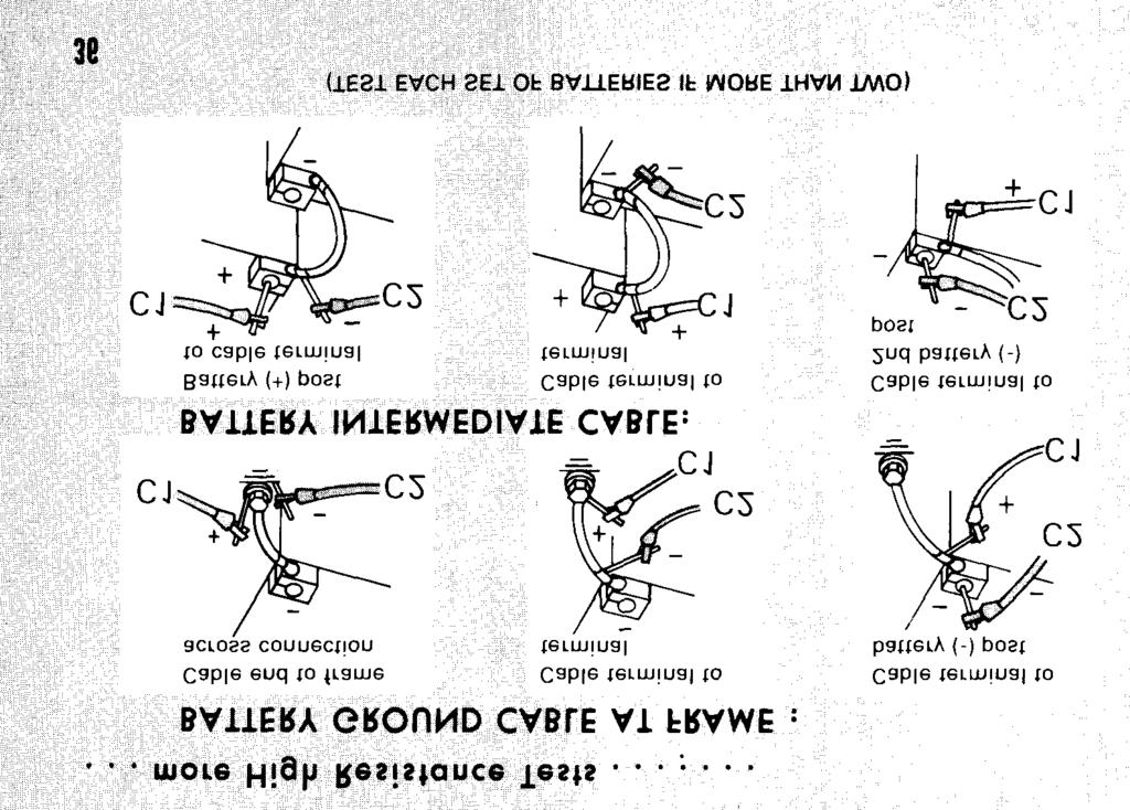
36 Test across each connection and cable at points shown until high resistance is found Use prods (tenpenny nails) clamped in each voltmeter lead alligator clip Vehicle ignition switch OFF, gear shift in neutral, and parking brake set Press prods hard at each bare metal point for good contact Have helper crank engine with starter switch While engine is cranking, see if voltmeter moves. If not... Switch to 10 volts. Still no movement... Switch to 1 volt needle If reading is more than 0.1 volt, it s a bad cable or connection Clean bad connections, reassemble and tighten, or replace the bad cable. Test again
37 WHY?... If during starter voltage test, the voltmeter registers less than 18 volts and batteries checked above 18 volts, these tests will find the high resistance cable or connection. Any high resistance connection must be removed. Have the mating surfaces cleaned, reassembled, and tightened. If it s a cable, replace it CAUTION: DO not crank engine over 30 seconds. If you do, let starter motor cool before cranking again Switch to 20 volts after each test is completed POSTS USED 5 - Voltmeter Voltmeter - SWITCHES & KNOBS Start Position 2 - OFF 3-20 volts 7 - Full Left (ccw) 10 - Full Left (ccw) 19 - Open 20 - Full Left (ccw) 21 - Closed 35
38 36
39 37

40 FIRST... ADAPTER HOOKUP Remove the battery system ground cable and connect adapters Reconnect battery ground cable after adapter hookup Generator adapter links OPEN Regulator adapter link CLOSED Polarize generator by connecting jumper lead C6 to regulator adapter terminal 1. Flash the other end to generator adapter field terminal 1. Remove jumper lead TEST Start and run engine at 1000 to 1200 rpm 2. Turn field rheostat clockwise slowly until voltmeter reads 30 volts 3. Load bank switch to ON 4. Turn coarse load bank knob clockwise slowly until ammeter reads specified output 5. keep adjusting knobs and until you get proper amperage at 30 volts 6. If you can t get these readings, either your generator drive belts are loose or the generator is faulty 38
41 WHY?... To test generator output and drive belt(s) for SIippage. (Run engine at 1000 to 1200 rpm during test) CAUTION Remove neg (-) battery terminal first and reconnect last POSTS USED 5 - Voltmeter Voltmeter Rheostat #1 8 - Rheostat # Load Bank 24V 16 - Ammeter - 100A SWITCHES & KNOBS Start Position 2 - OFF 3-50 volts 7 - Full Left (ccw) 10 - Full Left (ccw) 19 - Open 20 - Full Left (ccw) 21 - Closed 39
42 Above 80 F to 27.5 volts 0 F to 80 F to 28.0 volts Below 0 F to 28.5 volts TEST Start and run engine at 1000 to 1200 rpm (high NOTE: Some vehicles can t be started with link idle) on regulator adapter open. If yours is this type, start the engine with the link closed. After engine is started, open link 2. When engine is running smoothly, voltmeter needle should rest between 27.0 and 28.5 volts depending on the vehicle regulator specification 40
43 WHY?... To test for correct regulator setting. Systems in tactical vehicles should be set according to ambient temperature CAUTION Remove neg (-) battery terminal first and reconnect last POSTS USED 5 - Voltmeter Voltmeter - SWITCHES & KNOBS Start Position 2 - OFF 3-50 volts 7 - Full Left (ccw) 10 - Full Left (ccw) 19 - Open 20 - Full Left (ccw) 21 - Closed 41
44 Above 80 F to 27.5 volts 0 F to 80 F to 28.0 volts Below 0 F to 28.5 volts TEST Start and run engine at 1000 to 1200 rpm (high idle) NOTE: Some vehicles can t be started with link or regulator adapter open. If yours is this type, start the engine with the link closed. After engine is started, open link. When engine is running smoothly, voltmeter needle should rest between 27.0 and 28.5 volts depending on the vehicle regulator specification
45 43

46 TEST Start and run engine at 1000 to 1200 rpm (high idle) until smooth 2. Turn field rheostat clockwise slowly. Watch ammeter for needle flick. Voltmeter should read the cutout relay closing voltage between 24.5 and 26.5 volts at needle flick 3. The ammeter will show from 2 to 15 amperes at closing depending 4. on battery condition After you have relay closing voltage turn rheostat counterclockwise slowly. Watch ammeter needle as it travels left past zero to a point where it jumps back to zero 5. Cutout relay opening amperage is ammeter reading noted just before needle jumps back to zero 6. If relay doesn t close between 24.5 and 26.5 volts or doesn t open between 11 and 15 amperes, replace regulator 44
47 CAUTION Remove neg (-) battery terminal first and reconnect last POSTS USED 5 - Voltmeter Voltmeter Rheostat #1 8 - Rheostat # Ammeter Comm 17 - Ammeter -50A SWITCHES & KNOBS Start Position 2 - OFF 3-50 volts 7 - Full Left (ccw) 10 - Full Left (ccw) 19 - Open 20 - Full Left (ccw) 21 - Closed 45
48 TEST Start and run engine at 1000 to 1200 rpm (high idle) 2. Turn on load bank switch 3. Now adjust load bank knobs and slowly until voltmeter shows 27 to 28.5 volts Take your ammeter reading and remove load with load bank control knobs and. It should have read as specified for the regulator output current If your ammeter reading is less than specified for your vehicle, replace the regulator 46
49 47
50 TEST # Start and run engine at 1000 to 1200 rpm (high idle) 2. Turn rheostat nob slowly until 20 amperes is indicated on ammeter 3. Turn voltmeter switch to 10-volt position 4. With ammeter showing 20 amperes, voltmeter should not show over 0.8 volts. For a more accurate reading, switch to 1-volt position 5. If voltage is more than 0.8 volts, check both sections of cable for bad connections. Turn all controls off TEST # Remove lead C1 from ARM terminal and connect it to BAT adapter terminal. Repeat steps 2, 3, and 4 of test #1 2. If voltage is more than 0.8 volts, replace cable. If no voltage loss is found, replace cable tested in test #1 48
51 49
52 TEST Start and run engine at 1000 to 1200 rpm (high idle) Set voltmeter switch to 10-volt position Turn rheostat knob slowly clockwise until ammeter reads 20 amperes Now look at voltmeter Set switch. It should not indicate more than 0.1 volt to the 1-volt position for a more accurate reading Place switches and knobs in OFF position. Move black voltmeter cable C2 from generator frame and ground to regulator frame. With ammeter showing 20 amperes again, voltmeter should not read more than 0.1 volt 7. If voltmeter shows more than 0.1 volt on either test, look for loose generator or regulator mount, a loose, corroded, or bad battery to ground cable 50
53 WHY?. To find out if ground cable resistance is causing voltage loss with normal load current. This would cause undercharging of batteries CAUTION Remove neg (-) battery terminal first and reconnect last POSTS USED 5 - Voltmeter Voltmeter Rheostat #1 8 - Rheostat # Ammeter Comm 17 - Ammeter -50A SWITCHES & KNOBS Start Position 2 - OFF 3 - OFF 7 - Full Left (ccw) 10 - Full Left (ccw) 19 - Open 20 - Full Left (ccw) 21 - Closed 51
54 Facts of life concerning your Alternator Charging System: 1. NEVER reverse battery connections! Always hook up the positive (+) to positive (+) and negative (-) to negative (-). Negative wire or lead always goes to alternator frame 2. NEVER disconnect voltage regulator sensing lead while the engine is running! If you do, the alternator will burn itself out 3. NEVER ground the alternator output terminal! It ll cause an overload and burn out regulator 4. NEVER operate the alternator unless a load is connected to output terminal! 5. NEVER try to polarize an alternator! 6. There are two types of alternator charging systems. In one the rectifier is an internal part of the alternator. In the other the rectifier is an external component Here are sketches of the two types of alternator charging systems 52
55 53
56 TEST Turn on vehicle master switch 2. Start engine and run at 1000 to 1200 rpm 3. Now read voltmeter scale. It should show 27 to 29 volts 4. If voltmeter reads less than 27 volts or more than 29 volts, make a note of reading, then stop engine 5. With engine stopped, turn on master switch and again read voltmeter scale, If reading is the same as it was with engine running, turn off master switch and complete the second part of this test... 54
57 55

58 TEST... DO NOT START ENGINE! 1. Turn on master switch 2. Now read voltmeter. It should read 23 to 25 volts. If it reads low or zero, repair or replace master switch 3. When you get a 24-volt reading, turn OFF master switch, disconnect red voltmeter lead C1 from sensing lead connection, and reconnect lead between the master switch and alternator 4. Now repeat the hookup on test no. 1. Turn on master switch and run engine at 1000 to 1200 rpm. The voltmeter should show 28 volts (or voltage designated by your vehicle specification) 5. To adjust voltage output, remove plug from front flange and adjust until voltmeter shows 28 volts. Turning screw counterclockwise increases output voltage, while clockwise decreases it 6. If alternator cannot be adjusted, replace it 56
59 57
60 1. Turn master switch on 2. Start and run engine at 1000 to 1200 rpm 3. Turn load bank switch on Turn load bank knobs and slowly until ammeter shows amperes specified in vehicle specifications 5. Now look at voltmeter It should show voltage specified in vehicle specification. If it s less, turn alternator output adjustment screw counterclockwise and raise the output voltage specified If it will not adjust to voltage specified, but Output Tests #1 and #2 were OK, then you ll need to test battery to alternator cable and ground circuit for high resistance that could be causing a voltage drop 58
61 CAUTION Remove neg (-) battery terminal first and reconnect last POSTS USED 5 - Voltmeter Voltmeter Load Bank 24V 16 - Ammeter -100A SWITCHES & KNOBS Start Position 2 - OFF 3-50 volts 7 - Full Left (ccw) 10 - Full Left (ccw) 19 - Open 20 - Full Left (ccw) 21 - Closed 59
62 Start and run engine at 1000 to 1200 rpm Turn load bank switch on Adjust load bank knobs and 20 until ammeter shows 60 amperes Turn voltmeter switch to then and finally 1-volt position until you get a reading on voltmeter If reading is more than 1.0 volt, turn OFF engine you have a voltage loss Examine all connections and the cable itself between alternator and batteries for looseness, corrosion, frayed wires, bad cuts or dirt. After cleaning, tightening, or replacing bad cable, test again. The limit is 1.0 volt If you still get more than 1.0 volt... Disconnect black voltmeter lead C2 from the battery + post and hook it to alternator ground terminal bolt. Now take red voltmeter lead C1 from alternator output terminal and touch it to alternator cable at terminal block... then at the starter switch... and at the battery. At each point, watch for a sudden voltage jump. If you find such a point, you ve found the trouble. If each point has a drop of 1.0 volt or less and alternator output is still less than 27 volts, your next step is to test the alternator ground cable
63 WHY?... To find a bad connection or cable with high resistance causing excessive voltage drop CAUTION Remove neg (-) battery terminal first and reconnect last POSTS USED 5 - Voltmeter Voltmeter Load Bank 24V 16 - Ammeter -100A SWITCHES & KNOBS Start Position 2 - OFF 3-50 volts 7 - Full Left (ccw) 10 - Full Left (ccw) 19 - Open 20 - Full Left (ccw) 21 - Closed 61
64 TEST Start and run engine at 1000 to 1200 rpm 2. Turn load bank switch on Adjust load bank knobs and until ammeter reads 60 amperes Turn voltmeter switch down scale until voltmeter reads 0.1 volt. If it reads more than 0.1 volt, clean and tighten all connections Repeat alternator output test. If output cannot be adjusted to at least 27.5 volts after all cables have checked OK, replace the alternator 62

65 TEST DO NOT start engine! Keep master switch OFF 2. Touch black ammeter cable C4 to the alternator output terminal. The ammeter needle should only show a slight movement at contact. Any reading of needle after contact means there s current leakage in alternator. Replace alternator 64
66 WHY?... To see if alternator has internal leakage. If it does, it ll discharge the batteries. Replace a Ieaky alternator CAUTION Remove neg (-) battery terminal first and reconnect last POSTS USED 15 - Ammeter Comm 18 - Ammeter -10A SWITCHES & KNOBS Start Position 2 - OFF 3 - OFF 7 - Full Left (ccw) 10 - Full Left (ccw) 19 - Open 20 - Full Left (ccw) 21 - Closed 65
67 TEST DO NOT start engine! Keep master switch OFF 2. Touch black ammeter cable C4 to sensing lead connector. Ammeter needle should show only a slight movement at contact. Any reading of needle after contact means there s current leakage. Replace the sensing lead or alternator 66
68 WHY?.. To see if alternator sensing input has internal leakage. If it does, it ll discharge the batteries. Replace a leaky alternator 67
69 NOTES: 68 * U.S. GOVERNMENT PRINTING OFFICE : (0203)
70

71 TM

72 This fine document... Was brought to you by me: Liberated Manuals -- free army and government manuals Why do I do it? I am tired of sleazy CD-ROM sellers, who take publicly available information, slap watermarks and other junk on it, and sell it. Those masters of search engine manipulation make sure that their sites that sell free information, come up first in search engines. They did not create it... They did not even scan it... Why should they get your money? Why are not letting you give those free manuals to your friends? I am setting this document FREE. This document was made by the US Government and is NOT protected by Copyright. Feel free to share, republish, sell and so on. I am not asking you for donations, fees or handouts. If you can, please provide a link to liberatedmanuals.com, so that free manuals come up first in search engines: <A HREF= Military and Government Manuals</A> Sincerely Igor Chudov Chicago Machinery Movers
HARD TIME INTERVALS APPLY. DISTRIBUTION STATEMENT A
 LUBRICATION ORDER LO 9-2805-262-12 17 September 1991 (Supersedes LO 9-2805-203-12, 15 February 1990) ENGINE, GASOLINE 6 HP, MILITARY STANDARD MODELS (MODEL 4A032-1, NSN 2805-00-776-0483) (MODEL 4A32-2,
LUBRICATION ORDER LO JAN 84 (Supersedes LO , 25 FEBRUARY 1982)
") LUBRICATION ORDER LO 10 3930 632 12 10 JAN 84 (Supersedes, 25 FEBRUARY 1982) TRUCK, LIFT, FORK; GASOLINE ENGINE DRIVEN, SOLID RUBBER TIRED, 127-INCH LIFT; 2, 000 LB CAPACITY (CLARK EQUIPMEN-T MODEL 2329397,
LUBRICATION ORDER LO 10 3930 632 12 10 JAN 84 (Supersedes, 25 FEBRUARY 1982) TRUCK, LIFT, FORK; GASOLINE ENGINE DRIVEN, SOLID RUBBER TIRED, 127-INCH LIFT; 2, 000 LB CAPACITY (CLARK EQUIPMEN-T MODEL 2329397,
AIR TRANSPORTABILITY GUIDANCE TWO M151 1/4-TON TRUCKS AND ONE 1/4-TON TRAILER IN CH-47 HELICOPTER
 TM -2320-218-10-3 DEPARTMENT OF THE ARMY TECHNICAL MANUAL AIR TRANSPORTABILITY GUIDANCE TWO M11 1/4-TON TRUCKS AND ONE 1/4-TON TRAILER IN CH-47 HELICOPTER Headquarters, Department of the Army, Washington,
SPRAY GUN, PAINT MODEL NO. 76 (ECLIPSE SYSTEMS, INC,) (NSN )
 (NSN )") TM 9-4940-500-14&P TECHNICAL MANUAL OPERATOR'S ORGANIZATIONAL, DIRECT SUPPORT AND GENERAL SUPPORT MAINTENANCE MANUAL INCLUDING REPAIR PARTS LIST FOR SPRAY GUN, PAINT MODEL NO. 76 (ECLIPSE SYSTEMS, INC,)
TM 9-4940-500-14&P TECHNICAL MANUAL OPERATOR'S ORGANIZATIONAL, DIRECT SUPPORT AND GENERAL SUPPORT MAINTENANCE MANUAL INCLUDING REPAIR PARTS LIST FOR SPRAY GUN, PAINT MODEL NO. 76 (ECLIPSE SYSTEMS, INC,)
TECHNICAL MANUAL OPERATOR S, ORGANIZATIONAL, DIRECT SUPPORT AND GENERAL SUPPORT MAINTENANCE MANUAL INCLUDING REPAIR PARTS LIST FOR
 TM 9-4940-405-14&P TECHNICAL MANUAL OPERATOR S, ORGANIZATIONAL, DIRECT SUPPORT AND GENERAL SUPPORT MAINTENANCE MANUAL INCLUDING REPAIR S LIST FOR SPRAY OUTFIT, UNDERCOATING, MODEL 98-1030 (BINKS MANUFACTURING
*TB HEADQUARTERS, DEPARTMENT OF THE ARMY WASHINGTON, DC, 1 September 1999
 SEPTEMBER 999 *TB 5820 890 20 28 HEADQUARTERS, DEPARTMENT OF THE ARMY WASHINGTON, DC, September 999 REPORTING OF ERRORS AND RECOMMENDING IMPROVEMENTS You can help improve this manual. If you find any mistakes,
TEST SET, TACHOMETER DWELL (NSN )
") TM 9-4910-749-10 TECHNICAL MANUAL OPERATOR S MANUAL FOR TEST SET, TACHOMETER DWELL (NSN 4910-00-788-8549) McGRAW COMMERCIAL EQUIPMENT COMPANY, INC. HEADQUARTERS, DEPARTMENT OF THE ARMY MARCH 1984 SAFETY
TM 9-4910-749-10 TECHNICAL MANUAL OPERATOR S MANUAL FOR TEST SET, TACHOMETER DWELL (NSN 4910-00-788-8549) McGRAW COMMERCIAL EQUIPMENT COMPANY, INC. HEADQUARTERS, DEPARTMENT OF THE ARMY MARCH 1984 SAFETY
HAND RECEIPT MANUAL COVERING END ltem/components OF END ITEM (COEI), BASIC ISSUE ITEMS (Bll), AND ADDITIONAL AUTHORIZATION LIST (AAL) FOR
, BASIC ISSUE ITEMS (Bll), AND ADDITIONAL AUTHORIZATION LIST (AAL) FOR") TM9-2320-273-10-HR HAND RECEIPT MANUAL COVERING END ltem/components OF END ITEM (COEI), BASIC ISSUE ITEMS (Bll), AND ADDITIONAL AUTHORIZATION LIST (AAL) FOR TRUCK TRACTOR, LINE HAUL, 50,000 GVWR, 6X4,
TM9-2320-273-10-HR HAND RECEIPT MANUAL COVERING END ltem/components OF END ITEM (COEI), BASIC ISSUE ITEMS (Bll), AND ADDITIONAL AUTHORIZATION LIST (AAL) FOR TRUCK TRACTOR, LINE HAUL, 50,000 GVWR, 6X4,
TM &P TECHNICAL MANUAL
 TECHNICAL MANUAL OPERATOR S, ORGANIZATIONAL, DIRECT SUPPORT AND GENERAL SUPPORT MAINTENANCE MANUAL INCLUDING REPAIR PARTS LIST FOR BLAST CLEANING MACHINE MODEL SPECIAL 16W (PAULI & GRIFFIN COMPANY) (NSN
TECHNICAL MANUAL OPERATOR S, ORGANIZATIONAL, DIRECT SUPPORT, AND GENERAL SUPPORT MAINTENANCE MANUAL INCLUDING REPAIR PARTS LIST FOR
 TECHNICAL MANUAL OPERATOR S, ORGANIZATIONAL, DIRECT SUPPORT, AND GENERAL SUPPORT MAINTENANCE MANUAL INCLUDING REPAIR PARTS LIST FOR TESTER, HYDRAULIC MODEL PHT-100-6-G418-1 NSN 4910-00-868-6871 (SCHROEDER
TM HR HAND RECEIPT MANUAL
 HAND RECEIPT MANUAL COVERING THE END ltem/components OF END ITEM (COEI), BASIC ISSUE ITEMS (Bll), AND ADDITIONAL AUTHORIZATION LIST (ML) RELATED TO TRUCK, 5-TON, 6x6, M809 SERIES (DIESEL): CHASSIS, M809,
DEPARTMENT OF THE ARMY TECHNICAL MANUAL OPERATOR'S MANUAL. This copy is a reprint which includes current pages from Change 1.
 TM 9-4910-472-10 DEPARTMENT OF THE ARMY TECHNICAL MANUAL OPERATOR'S MANUAL TEST SET, GENERATOR AND VOLTAGE REGULATOR, AUTOMOTIVE: 6, 12, AND 24 VOLT SYSTEMS (SUN ELECTRIC CORP., MODEL NO. VAT-25) (4910-270.3780)
NORMAL. MWO effective date 1 June 1992 and completion date 30 May 1994 MODIFICATION WORK ORDER
 NORMAL MWO effective date 1 June 1992 and completion date 30 May 1994 MWO 9-2320-279-34-1 MODIFICATION WORK ORDER MODIFICATION OF M977 SERIES HEAVY EXPANDED MOBILITY TACTICAL TRUCK (HEMTT) INSTALLATION
HEADQUARTERS, DEPARTMENT OF THE ARMY
 TM 9-4910-631-14 & P DEPARTMENT OF THE ARMY TECHNICAL MANUAL OPERATOR, ORGANIZATIONAL, DIRECT SUPPORT AND GENERAL SUPPORT MAINTENANCE MANUAL INCLUDING REPAIR PARTS LIST FOR CLEANER & TESTER, SPARK PLUG
DEPARTMENT OF THE ARMY TECHNICAL MANUAL
 DEPARTMENT OF THE ARMY TECHNICAL MANUAL * EQUIPMENT SERVICEABILITY CRITERIA FOR COMPRESSOR, RECIPROCATING, AIR, POWER DRIVEN, HIGH PRESSURE 4 CFM AND UP, 1000 PSI AND UP GROUP I - FOUR WHEEL MTD, PNEUMATIC
LO DECEMBER 83 (Supersedes LO , and -2, 30 JANUARY 1976)
") LUBRICATION ORDER LO 10-3930-634-12 15 DECEMBER 83 (Supersedes LO 10-3930-634-12-1, and -2, 30 JANUARY 1976) TRUCK, LIFT, FORK, DIESEL ENGINE, PNEUMATIC TIRED WHEELS, 6000 LB CAPACITY, 24 INCH LOAD CENTER,
LUBRICATION ORDER LO 10-3930-634-12 15 DECEMBER 83 (Supersedes LO 10-3930-634-12-1, and -2, 30 JANUARY 1976) TRUCK, LIFT, FORK, DIESEL ENGINE, PNEUMATIC TIRED WHEELS, 6000 LB CAPACITY, 24 INCH LOAD CENTER,
BLAST CLEANING MACHINE
 TM 9-4940-658-4&P TECHNICAL MANUAL OPERATOR S, ORGANIZATlONAL, DIRECT SUPPORT AND GENERAL SUPPORT MAINTENANCE MANUAL INCLUDING REPAIR PARTS LIST FOR BLAST CLEANING MACHINE MODELS 5L, 25L, 35W, 00, 200E,
MODIFICATION WORK ORDER
 CHANGE NO.1 HEADQUARTERS DEPARTMENT OF THE ARMY Washington D.C.,24 May 1993 MODIFICATION WORK ORDER VEHICLE MODEL NSN Truck, Utility, 1-1/4 Ton, 4x4: Cargoflroop Carrier Cargo/Troop Carrier, W/Winch TOW
ORDER LO LI-00664G MAY 1975 (Supersedes L dated 6 APRIL 1973)
") LUBRICATION ORDER LO 5-4210-217-12 LI-00664G-12 15 MAY 1975 (Supersedes L05-4210-217-12 dated 6 APRIL 1973) TRUCK, FIRE FIGHTING: POWERED PUMPER; FOAM AND WATER 750 G.P.M. CAP.; CENTRIFUGAL PUMP, POWER
LUBRICATION ORDER LO 5-4210-217-12 LI-00664G-12 15 MAY 1975 (Supersedes L05-4210-217-12 dated 6 APRIL 1973) TRUCK, FIRE FIGHTING: POWERED PUMPER; FOAM AND WATER 750 G.P.M. CAP.; CENTRIFUGAL PUMP, POWER
Electronic Dynamo Regulator INSTRUCTION MANUAL. COPYRIGHT 2015 CLOVER SYSTEMS All Rights Reserved
 DR310 TM Electronic Dynamo Regulator INSTRUCTION MANUAL COPYRIGHT 2015 CLOVER SYSTEMS All Rights Reserved INTRODUCTION The Clover Systems DR310 is an allelectronic voltage and current regulator for dynamos
STARTING SYSTEM (1ZZ FE) (April, 2003)
 (April, 2003)") STARTING & CHARGING STARTING SYSTEM (1ZZ FE) (April, 2003) STARTING SYSTEM (1ZZ FE) (April, 2003) INSPECTION 19 1 190QO 02 1. INSPECT STARTER ASSY NOTICE: These tests must be performed within 3 to 5 seconds
STARTING & CHARGING STARTING SYSTEM (1ZZ FE) (April, 2003) STARTING SYSTEM (1ZZ FE) (April, 2003) INSPECTION 19 1 190QO 02 1. INSPECT STARTER ASSY NOTICE: These tests must be performed within 3 to 5 seconds
ALTERNATOR - CHRYSLER 40/90-AMP & 50/120 AMP
 ALTERNATOR - CHRYSLER 40/90-AMP & 50/120 AMP 1988 Chrysler LeBaron Convert/Coupe 1988 ELECTRICAL Chrysler Motors 40/90 & 50/120 Amp Alternators FWD Models DESCRIPTION The charging system consists of an
ELECTRICAL BATTERY/STARTING/CHARGING SYSTEMS DIAGNOSTICS
 Z ELECTRICAL 8A - 1 ELECTRICAL GROUP INDEX page AUDIO SYSTEMS... 8F BATTERY/STARTER/GENERATOR SERVICE... 8B BATTERY/STARTING/CHARGING SYSTEMS DIAGNOSTICS... 8A CHIME WARNING/REMINDER SYSTEM... 8U HORNS...
STARTING SYSTEMS 8B - 1 STARTING SYSTEMS CONTENTS
 TJ STARTING SYSTEMS 8B - 1 STARTING SYSTEMS CONTENTS page DESCRIPTION AND OPERATION STARTER MOTOR... 2 STARTER RELAY... 3 STARTING SYSTEM... 1 DIAGNOSIS AND TESTING STARTER MOTOR... 8 STARTER MOTOR NOISE
2008 Toyota RAV ELECTRICAL Charging (2AZ-FE) - RAV4
 - RAV4") 2008 ELECTRICAL Charging (2AZ-FE) - RAV4 CHARGING SYSTEM PRECAUTION 1. Check that the battery cables are connected to the correct terminals. 2. Disconnect the battery cables if a quick charge is given
2008 ELECTRICAL Charging (2AZ-FE) - RAV4 CHARGING SYSTEM PRECAUTION 1. Check that the battery cables are connected to the correct terminals. 2. Disconnect the battery cables if a quick charge is given
Simplified Check Program for Charging Systems
 SB-3 Battery Load Tester Instruction Manual Simplified Check Program for Charging Systems The SB-3 is a variable load battery tester that provides a simplified check for the alternator and starter. CONGRATULATIONS
INFORMATION. covering use of Ammeter and Voltmeter ON and 1915 Model Six-54 Electrical System
 INFORMATION covering use of Ammeter and Voltmeter ON- 1914 and 1915 Model Six-54 Electrical System Hudson Motor Car Company Detroit, Michigan, IX S. A USE OF AMMETER ON 1914 AND 1915 MODEL SIX-54 With
STARTER CIRCUIT TROUBLESHOOTING
 2000 Honda Accord EX Sedan V6-3.0L Vehicle > Starting and Charging > Starting System > Starter Motor > Testing and Inspection > Component Tests and General Diagnostics STARTER CIRCUIT TROUBLESHOOTING Starter
ELECTRICAL. CDTA Technical Training Center
 ELECTRICAL ATOMIC STRUCTURE Protons positive charge Electron negative charge Neutron - neutral Electricity is the movement of electrons from atom to atom ELECTRON FLOW CONDUCTOR - Materials which have
Table No. 1 provides a means of identifying the various alternator systems. Note: All output figures are rated at 3600 RPM. TABLE NO.
 The alternator systems installed on Briggs & Stratton Intek OHV-Twin Cylinder Engines can easily be identified by the color of the stator output wires and the connector. Table No. 1 provides a means of
ON-VEHICLE INSPECTION
 CH2 P11586 CHARGING CHARGING SYSTEM ONVEHICLE INSPECTION 1. CHECK BATTERY ELECTROLYTE LEVEL Check the electrolyte quantity of each cell. MaintenanceFree Battery: CH03L01 If under the lower level, replace
CHARGING SYSTEM ON-VEHICLE INSPECTION
 CHARGING (2UZFE) CHARGING SYSTEM CHARGING SYSTEM ONVEHICLE INSPECTION CH1 CH0J603 CAUTION: Check that the battery cables are connected to the correct terminals. Disconnect the battery cables when the battery
Page 1 of 1 ALTERNATORS. Overview. Intek TM V-Twin Cylinder OHV Engine Service Manual Version 1.0. Copyright 1999 by Briggs and Stratton Corporation
 Overview Alternator Identification Page 1 of 3 The alternator systems installed on Briggs & Stratton Intek V-Twin Cylinder OHV Engines can easily be identified by the color of the stator output wires and
BATTERY 8A - 1 BATTERY CONTENTS
 TJ BATTERY 8A - 1 BATTERY CONTENTS page DESCRIPTION AND OPERATION BATTERY... 1 DIAGNOSIS AND TESTING BATTERY... 3 SERVICE PROCEDURES BATTERY CHARGING... 13 DESCRIPTION AND OPERATION BATTERY DESCRIPTION
Electronic Dynamo Regulator INSTRUCTION MANUAL. COPYRIGHT 2014 CLOVER SYSTEMS All Rights Reserved
 DRM TM DRM-HP TM Electronic Dynamo Regulator INSTRUCTION MANUAL COPYRIGHT 2014 CLOVER SYSTEMS All Rights Reserved INTRODUCTION The Clover Systems DRM is a state-of-the art all-electronic voltage and current
C.E. Niehoff & Co. N1601, N1602, N1603, and N1604 Alternator Troubleshooting Guide NOTICE. Hazard Definitions. Battery Charge Volt and Amp Values
 C.E. Niehoff & Co. N1601, N1602, N1603, and N1604 Alternator Troubleshooting Guide Hazard Definitions These terms are used to bring attention to presence of hazard(s) of various risk levels or to important
2000 F-150 Workshop Manual
 Page 1 of 14 SECTION 303-06: Starting System 2000 F-150 Workshop Manual DIAGNOSIS AND TESTING Procedure revision date: 06/17/1999 Starting System Refer to Wiring Diagrams Cell 20, Starting System for schematic
Battery Tester. GxT Incorporated, Cheboygan MI, U.S.A. All Rights Reserved E040-01G. 40 & 42HD Operator s Manual
 Battery Tester GxT Incorporated, Cheboygan MI, U.S.A. All Rights Reserved E040-01G 40 & 42HD Operator s Manual SPECIFICATIONS Measurement Range...Ferret 40... Ferret 42HD Battery Volts... 4.0 to 19.99...
Quality Test Equipment Since 1957 OPERATOR S MANUAL
 Quality Test Equipment ince 1957 OPERATOR MANUAL Congratulations! On your new purchase of Auto Meter s Charging/tarting ystem Analyzer. It is designed to test each component of a vehicle s electrical system
Electrical Systems. Introduction
 Electrical Systems Figure 1. Major Components of the Car s Electrical System Introduction Electricity is used in nearly all systems of the automobile (Figure 1). It is much easier to understand what electricity
ALTERNATOR - BOSCH 35/75-AMP & 40/90-AMP
 ALTERNATOR - BOSCH 35/75-AMP & 40/90-AMP 1988 Chrysler LeBaron Convert/Coupe 1988 ALTERNATORS & REGULATORS Chrysler Motors - Bosch 35/75 & 40/90 Amp Alternator All Models DESCRIPTION The charging system
BATTERY CHARGER-STARTER
 BATTERY CHARGER-STARTER MODEL NO: WBC240 & WBC400 PART NO: 6261505 & 6261515 OPERATION & MAINTENANCE INSTRUCTIONS GC0116 INTRODUCTION Thank you for purchasing this CLARKE Battery Charger/Starter. Please
1984 Jeep CJ7. IGNITION SYSTEM - SOLID STATE' 'Distributors & Ignition Systems MOTORCRAFT SOLID STATE IGNITION (SSI)
") TESTING SECONDARY CIRCUIT CHECK CAUTION: When checking secondary voltage, do not remove spark plug wires from spark plugs No. 3 on 4-cylinder, No. 1 or 5 on 6-cylinder and No. 3 or 4 on V8 Engines. 1.
TESTING SECONDARY CIRCUIT CHECK CAUTION: When checking secondary voltage, do not remove spark plug wires from spark plugs No. 3 on 4-cylinder, No. 1 or 5 on 6-cylinder and No. 3 or 4 on V8 Engines. 1.
COMBINATION METER BE 45 PARTS LOCATION
 BE45 PARTS LOCATION BE46 BODY ELECTRICAL SYSTEM METER CIRCUIT BE47 TROUBLESHOOTING The table below will be useful for you in troubleshooting these electrical problems. The most likely causes of the malfunction
DIAGNOSIS AND TESTING Procedure revision date: 06/21/2000
 2001 F-350 Applies to: Gasoline Report a problem with this article Subarticles Inspection and Verification Symptom Chart Pinpoint Tests Component Tests SECTION 303-06A: Starting System Gasoline Engines
C802/C802D/C802TD/C820 Alternators Troubleshooting Guide
 C802/C802D/C802TD/C820 Alternators Troubleshooting Guide Hazard Definitions These terms are used to bring attention to presence of hazards of various risk levels or to important information concerning
Automotive Electrical Systems
 Automotive Electrical Systems 1 Electrical Circuits Contain 4 main parts 1. Power source battery alternator 2. Load 3. Control 4. Path 2 3 Batteries What is a Battery? An electrochemical device which stores
FC/FCA 12, 24, 32 & 48 VOLT, 6 & 10 AMP BATTERY CHARGER OPERATION & MAINTENANCE GUIDE
 FC/FCA 12, 24, 32 & 48 VOLT, 6 & 10 AMP BATTERY CHARGER OPERATION & MAINTENANCE GUIDE SENS part number: 101037 Document revision: A Engineering change number: 105073 Date: 1/13/2006 1840 Industrial Circle
RELEASING PRESSURE IN THE HYDRAULIC SYSTEM,
 Testing And Adjusting Introduction NOTE: For Specifications with illustrations, make reference to SPECIFICATIONS for 225 EXCAVATOR HYDRAULIC SYSTEM, Form No. SENR7734. If the Specifications are not the
IMPORTANT SAFETY INSTRUCTIONS
 ASSOCIATED Model 6039 Battery Tester Operator's Manual IMPORTANT SAFETY INSTRUCTIONS 1. SAVE THESE INSTRUCTIONS This manual contains important safety and operating instructions for the battery tester you
DIAGNOSIS AND TESTING
 414-00-1 Charging System General Information 414-00-1 DIAGNOSIS AND TESTING Charging System The charging system voltage is controlled by the PCM. The generator charges the battery, and at the Special Tool(s)
C.E. Niehoff & Co. C653/C653A and C625 Alternators Troubleshooting Guide NOTICE. Hazard Definitions. Battery Charge Volt and Amp Values
 C.E. Niehoff & Co. C653/C653A and C625 Alternators Troubleshooting Guide Hazard Definitions These terms are used to bring attention to presence of hazards of various risk levels or to important information
BE 30 BODY ELECTRICAL SYSTEM. Combination Meter COMBINATION METER. Parts Location
 BE30 BODY ELECTRICAL SYSTEM COMBINATION METER Parts Location BODY ELECTRICAL SYSTEM BE31 Meter Circuit (w/o Tachometer) No. 2 7 9 12 1 2 3 5 7 9 3 Wiring connector side ETC Pattern select switch A/T Oil
BEST 6042 BATTERY TESTER
 ASSOCIATED BEST 6042 BATTERY TESTER OPERATOR AND SAFETY MANUAL The BEST 6042 is designed to test electrical systems on 12, 12/24, and 24 volt vehicles. It can test and evaluate starters, batteries, alternators,
ANTI-LOCK BRAKE SYSTEM
 ANTI-LOCK BRAKE SYSTEM 1993 Mitsubishi Diamante 1993 BRAKES Mitsubishi - Anti-Lock Brake System Diamante DESCRIPTION The Anti-Lock BRAKE SYSTEM (ABS) is designed to prevent wheel lock-up during heavy braking.
PHYSICS MCQ (TERM-1) BOARD PAPERS
 BOARD PAPERS") GRADE: 10 PHYSICS MCQ (TERM-1) BOARD PAPERS 1 The number of division in ammeter of range 2A is 10 and voltmeter of range 5 V is 20. When the switch of the circuit given below is closed, ammeter reading
GRADE: 10 PHYSICS MCQ (TERM-1) BOARD PAPERS 1 The number of division in ammeter of range 2A is 10 and voltmeter of range 5 V is 20. When the switch of the circuit given below is closed, ammeter reading
24-00 ELECTRICAL POWER
 ELECTRICAL POWER 1. GENERAL This chapter contains information on DC Generation, External Power, and Electrical Load Distribution. The airplane is equipped with a two-alternator, two-battery, 28-volt direct
BATTERY 8A - 1 BATTERY CONTENTS
 ZJ BATTERY 8A - 1 BATTERY CONTENTS page GENERAL INFORMATION INTRODUCTION... 1 OVERVIEW... 1 DESCRIPTION AND OPERATION BATTERY MOUNTING... 3 BATTERY SIZE AND RATINGS... 2 BATTERY... 2 DIAGNOSIS AND TESTING
MODEL 6010A 6 12 VOLT BATTERY CHARGER ASSOCIATE
 MODEL 600A 6 VOLT BATTERY CHARGER ASSOCIATE IMPORTANT SAFETY INSTRUCTIONS. SAVE THESE INSTRUCTIONS. This manual contains important safety and operating instructions for the battery charger you have purchased.
This chapter contains information on DC Generation, External Power, and Electrical Load Distribution.
 CIRRUS AIRPLANE MAINTENANCE MANUAL Electrical Power CHAPTER 24-00: ELECTRICAL POWER GENERAL 24-00: ELECTRICAL POWER 1. General This chapter contains information on DC Generation, External Power, and Electrical
STARTING SYSTEM TEST STARTING SYSTEM
 2013 Dodge or Ram Truck RAM 1500 Truck 2WD V8-5.7L Vehicle > Starting and Charging > Starting System > Testing and Inspection > Component Tests and General Diagnostics STARTING SYSTEM TEST STARTING SYSTEM
Battery Management Innovation. For 12-volt automotive starting batteries and starting/charging systems INSTRUCTION MANUAL
 Battery Management Innovation For 12-volt automotive starting batteries and starting/charging systems INSTRUCTION MANUAL ! CAUTION Because of the possibility of personal injury, always use extreme caution
TEST SET, TACHOMETER, DWELL (AUL INSTRUMENTS, INC.) (NSN )
 (NSN )") TECHNICAL MANUAL TM 9-4910-700-14&P OPERATOR S, ORGANIZATIONAL,. DIRECT SUPPORT AND GENERAL SUPPORT MAINTENANCE MANUAL lncluding REPAIR PARTS LIST FOR TEST SET, TACHOMETER, DWELL (AUL INSTRUMENTS, INC.)
TECHNICAL MANUAL TM 9-4910-700-14&P OPERATOR S, ORGANIZATIONAL,. DIRECT SUPPORT AND GENERAL SUPPORT MAINTENANCE MANUAL lncluding REPAIR PARTS LIST FOR TEST SET, TACHOMETER, DWELL (AUL INSTRUMENTS, INC.)
NILFISK BA 500 Service Manual
 NILFISK BA 500 Service Manual Model 66324400 12/94 Form Number 043023 TABLE OF CONTENTS Batteries...21 Brush Drive Belt Adjustment Or Replacement...7 Brush Drive Motor - Carbon brush Inspection... 8 Brush
Troubleshooting Guide for N1225-1/N1237-1/N Alternators
 Troubleshooting Guide for N1225-1/N1237-1/N1505-1 Alternators Hazard Definitions These terms are used to bring attention to presence of hazards of various risk levels or to important information concerning
CHARGING SYSTEM CHARGING SYSTEM CH 1
 CH1 CH2 Precautions PRECAUTIONS 1. Check that the battery cables are connected to the correct terminals. 2. Disconnect the battery cables when the battery is given a quick charge. 3. Do not perform tests
DEPARTMENT OF THE ARMY TECHNICAL MANUAL
 DEPARTMENT OF THE ARMY TECHNICAL MANUAL EQUIPMENT SERVICEABILITY CRITERIA FOR POWER PLANT, UTILITY, PORTABLE, GAS TURBINE ENGINE DRIVEN, SKID MTD, AIRESEARCH MDL PPU85-5 NON- WINTERIZED, FSN 6115-937-0929,
Starter, Delco Remy 15.01
 Starter, Delco Remy.0 General Information General Information The Delco Remy starter mounts at the forward face of the flywheel bell housing on the right side of the engine. The starter assembly consists
2001 Cougar Workshop Manual
 Page 1 of 7 SECTION 303-06: Starting System 2001 Cougar Workshop Manual DIAGNOSIS AND TESTING Procedure revision date: 09/14/2001 Starting System Refer to Wiring Diagrams Section 303-06 for schematic and
MDX-300 Series. For 12-volt automotive starting batteries and starting/charging systems INSTRUCTION MANUAL
 For 12-volt automotive starting batteries and starting/charging systems INSTRUCTION MANUAL Blank page Contents Caution... 4 Capabilities... 4 Display and Keypad... 4 Preparations Before the Test... 6 Connecting
Automatic taper of charge rate for superior battery life through good equalization of cells and low water use rate.
 FEATURES Automatic taper of charge rate for superior battery life through good equalization of cells and low water use rate. Silicon diodes with inherent surge protection operated at a conservative percentage
Troubleshooting Bosch Proportional Valves
 Troubleshooting Bosch Proportional Valves An Informative Webinar Developed by GPM Hydraulic Consulting, Inc. Instructed By Copyright, 2009 GPM Hydraulic Consulting, Inc. TABLE OF CONTENTS Bosch Valves
Phase 1 Workshop Home Study Guide
 Phase 1 Workshop Home Study Guide Vehicle Electrical-Electronics Troubleshooting Training Written and Developed by Vince Fischelli Director of Training Veejer Enterprises Inc. / Garland, Texas U.S.A. Phone:
17. BATTERY/CHARGING SYSTEM
 17 17 BATTERY/CHARGING SYSTEM CHARGING SYSTEM LAYOUT/CHARGING CIRCUIT ----------- 17-1 SERVICE INFORMATION------------------------------------------------ 17-2 TROUBLESHOOTING-----------------------------------------------------
Northwest RV Supply Manual Compliments of Printed From TROUBLESHOOTING
 TROUBLESHOOTING for the 5 BUTTON 3109228.001 COMFORT CONTROL CENTER SYSTEM INTRODUCTION The Comfort Control Center control system can be used to operate the following Duo-Therm Units: Roof Top Air Conditioners
Today, we re going to talk about battery safety. We ll discuss all the key issues associated with using batteries safely, including battery hazards,
 Today, we re going to talk about battery safety. We ll discuss all the key issues associated with using batteries safely, including battery hazards, battery charging, and battery maintenance. Although
1. SPECIFICATION
 000000 093 1. SPECIFICATION Specification HPS EPS Alternator Crankshaft pulley : Alternator Pulley 1 : 2.94 Normal output (idling/2200 rpm) 70/120 A 70/140A Regulator voltage 14.6 V Brush Length 12.5 mm
BE 46 COMBINATION METER PARTS LOCATION
 BE46 PARTS LOCATION METER CIRCUIT w/o Tachometer BE47 BE48 w/ Tachometer TROUBLESHOOTING The table below will be useful for you in troubleshooting these electrical problems. The most likely causes of the
ON-VEHICLE INSPECTION
 2007 Sequoia SR5 Last Modified: 2010-5-6 00:00:00 G From:200608 Report a problem with this article Model Year: 2007 Model: Sequoia Doc ID: RM00000188V004X Engine Family: 2UZ-FE, A750E 2UZ-FE, A750F Body
Electronic Dynamo Regulator INSTRUCTION MANUAL. COPYRIGHT 2014 CLOVER SYSTEMS All Rights Reserved
 DRM TM DRM-HP TM Electronic Dynamo Regulator INSTRUCTION MANUAL COPYRIGHT 2014 CLOVER SYSTEMS All Rights Reserved INTRODUCTION The Clover Systems DRM is a state-of-the art all-electronic voltage and current
MODEL No. BC 700. Par t No OPERATING & MAINTENANCE INSTRUCTIONS
 BATTERY BOOSTER/CHARGER MODEL No. BC 700 Par t No.6260025 OPERATING & MAINTENANCE INSTRUCTIONS Congratulations on the purchase of your new CLARKE, START N CHARGE 700, BATTERY BOOSTER/CHARGER. This 3 Phase
Tension Control System MCS-166, MCS-203, MCS-204
 Tension Control System MCS-166, MCS-203, MCS-204 P-257-WE 819-9027 Installation & Operation Instructions An Altra Industrial Motion Company Table of Contents Introduction...3 Specifications... 3-4 Installation
Technical Workshop: Electrical December 3, 2016
 Technical Workshop: Electrical December 3, 2016 ELECTRICAL: CIRCUITS Key terms we will be using today: Voltage (V): The difference in electrical potential at one point in a circuit in relation to another.
A/C-HEATER SYSTEM - AUTOMATIC
 A/C-HEATER SYSTEM - AUTOMATIC 1988 Toyota Celica 1988 Automatic A/C-Heater Systems Celica * PLEASE READ THIS FIRST * CAUTION: When discharging air conditioning system, use only approved refrigerant recovery/recycling
PROCESS ELECTRONICS CORPORATION
 MINIVERTER MANUAL PROCESS ELECTRONICS CORPORATION 100 BRICKYARD ROAD MOUNT HOLLY, NORTH CAROLINA 28120 TELEPHONE (800) 421-9107 FAX (704) 827-9595 SALES@PECRECTIFIER.COM WWW.PECRECTIFIER.COM SOLID STATE
IMPORTANT SAFETY INSTRUCTIONS
 Table of Contents Safety... 2 Specifications... 3 Functions... 4 Operation... 5 Maintenance... 7 Warranty... 7 SAFETY SPECIFICATIONS OPERATION MAINTENANCE WARNING SYMBOLS AND DEFINITIONS This is the safety
CHARGING SYSTEM PRECAUTION CH 1
 1NZ-FE ARGING ARGING SYSTEM ARGING SYSTEM PRECAUTION 1 1. Check that the battery cables are connected to the correct terminals. 2. Disconnect the battery cables when the battery is given a quick charge.
34.5 Electric Current: Ohm s Law OHM, OHM ON THE RANGE. Purpose. Required Equipment and Supplies. Discussion. Procedure
 Name Period Date CONCEPTUAL PHYSICS Experiment 34.5 Electric : Ohm s Law OHM, OHM ON THE RANGE Thanx to Dean Baird Purpose In this experiment, you will arrange a simple circuit involving a power source
A/C Generator Systems
 A/C Generator Systems What is the function of the charging system? Provide power for all electrical loads Recharge the starting battery What happens if the charging systems puts out too much power? Voltage
SP6. Automatic Battery Charger. Model
 Model SP6 Automatic Battery Charger OWNERS MANUAL PLEASE SAVE THIS OWNERS MANUAL AND READ BEFORE EACH USE. This manual will explain how to use the charger safely and effectively. Please read and follow
ALTERNATOR PRECAUTIONS. Some precautions should be taken when working on this, or any other, AC charging system.
 The alternator charging system is a negative (-) ground system which consists of an alternator, a regulator, a charge indicator, a storage battery and wiring connecting the components, and fuse link wire.
Alternator, Leece-Neville 15.00
 Alternator, Leece-Neville 5.00 General Information General Description The Leece-Neville JB series alternator is a 4-volt self-load-limiting alternator equipped with a threestep adjustable voltage regulator.
ST- 1 STARTING SYSTEM. Page TROUBLESHOOTING... ST-2 STARTER... ST-3 STARTER RELAY... ST- 12 CLUTCH START SWITCH... ST-1 2
 ST- 1 STARTING SYSTEM Page TROUBLESHOOTING... ST-2 STARTER... ST-3 STARTER RELAY... ST- 12 CLUTCH START SWITCH... ST-1 2 ST-2 STARTING SYSTEM - Troubleshooting TROUBLESHOOTING Problem Possible cause Remedy
CHAPTER 10 ELECTRIC SYSTEM
 CHAPTER 10 ELECTRIC SYSTEM 1. ELECTRIC SYSTEM ELECTRIC SYSTEM 1.1 WIRING DIAGRAM CK20-USA 196WA00A S196-WOO Jul. 2003 10-3 CK20(M) CHAPTER 10 CK20-EU 196WA51A 10-4 S196-WOO Jul. 2003 ELECTRIC SYSTEM 1.2
CHARGING SYSTEM. Page PRECAUTIONS... CH-2 TROUBLESHOOTING... CH-2 ON-VEHICLE INSPECTION... CH-2 ALTERNATOR... CH-6
 CHARGING SYSTEM Page PRECAUTIONS... CH-2 TROUBLESHOOTING... CH-2 ON-VEHICLE INSPECTION... CH-2 ALTERNATOR... CH-6 CH-2 CHARGING SYSTEM - Precautions, Troubleshooting,On-Vehicle Inspection PRECAUTIONS 1.
CHARGING SYSTEM 8C - 1 CHARGING SYSTEM CONTENTS
 ZG CHARGING SYSTEM 8C - 1 CHARGING SYSTEM CONTENTS page GENERAL INFORMATION OVERVIEW... 1 DESCRIPTION AND OPERATION BATTERY TEMPERATURE SENSOR... 2 CHARGING SYSTEM OPERATION... 1 ELECTRONIC VOLTAGE REGULATOR...
STARTING & CHARGING SYSTEM
 K ELECTRICAL SECTION SC A STARTING & CHARGING SYSTEM B C D CONTENTS E PRECAUTIONS... 2 Precautions for Supplemental Restraint System (SRS) AIR BAG and SEAT BELT PRE-TEN- SIONER... 2 Precautions for Power
ELECTRICAL. Contents - Wiring Diagrams
 Contents - Wiring Diagrams T-Bar (Floating Deck - Hydro)............................................ 8-16 T-Bar (Fixed Deck - Gear)............................................... 8-17 T-Bar (Fixed Deck
Battery Operation. Battery Construction. Battery State Of Charge. Battery Load Test. Battery Rating Systems 2/14/12
 Battery Operation Batteries, Charging and Donald Jones Brookhaven College Batteries convert chemical energy into electrical energy During discharge the battery s plate composition is changed During charging
Electrical Testing in the Operating Room; Part 6
 DOCTORDOCTOR It hurts when I shift! by Randall Schroeder Electrical Testing in the Operating Room; Part 6 IIn the operating room, doctors are faced with precise test procedures that are challenging and