LXIPEB33 505,038M MARCH 14, 2012 SUPERCEDES
|
|
|
- Moses Price
- 5 years ago
- Views:
Transcription
 USED 242-360 UNITS SHIP PING AND PACK ING LIST Package 1 of 1 contains: See Illustration 1 and 2. 1 - Power Exhaust Assembly a.")
 #10-16 x ½\" 1 - Installation Instructions 2 - Wiring Stickers 3 - Wire Ties WARNING Improper installation,")
1 ENERGENCE & L SE RIES KITS AND AC CES SO RIES LXIPEB33 505,038M MARCH 14, 2012 SUPERCEDES LAPEB 30/36 LAPEV 30/36 IN STAL LA TION IN STRUC TIONS FOR HIGH STATIC POWER EXHAUST FAN (PEB) AND HIGH STATIC POWER EXHAUST FAN WITH VARIABLE FREQUENCY DRIVE (PEV) USED UNITS SHIP PING AND PACK ING LIST Package 1 of 1 contains: See Illustration 1 and Power Exhaust Assembly a. Outdoor Exhaust Air Hood(s) w/ Barometric Damper(s) b. Sub-Fused Control Box w/ Factory Installed High Voltage Connecting Harness c. Low Voltage Harness for Communication from Rooftop Unit. 1 - Adapter Panel 1 - Hardware Bag Assembly 14' - Gasket ¾" x ¼" 10 - Self-tapping Screw(s) #10-16 x ½" 1 - Installation Instructions 2 - Wiring Stickers 3 - Wire Ties WARNING Improper installation, adjustment, alteration, service or maintenance can cause property damage, personal injury or loss of life. Installation and service must be performed by a qualified installer or service agency. PRINCIPLE OF OPERATION The power exhaust contains forward curve belt driven blower assemblies with (3) three phase motors using variable pitch sheaves on PEV models a variable frequency drive (VFD) in installed. These blower assemblies are located in the cabinet that attaches to the rooftop unit horizontal return air section. When the rooftop unit provides a signal to operate, a contactor located in the power exhaust control box is energized, providing high voltage power to each motor. This allows the blower assemblies to exhaust air from the building through the return air duct work of the rooftop unit. On the PEV models a pressure differential is measured between outside air and return air and a signal is sent to VFD for change of motor speed. CAUTION Electric shock hazard. Can cause injury or death. Before attempting to perform any service or maintenance, turn the electrical power to unit OFF at disconnect switch(es). Unit may have multiple power supplies. 80 ½" (2044.7) 22" (558.8) 17" (431.8) SUPPORT LEGS BAROMETRIC DAMPERS " (361.2) EXHAUST AIR 28" (711.2) CONTROL ACCESS PANEL SUPPORT LEGS BLOWER ACCESS PANEL Illustration 1 PAGE 1
 30 1316 \" (782.6) 1\" (25.4) 1\" (25.4) 17\" (431.8) 17\" (431.8) 5\" (127) SUPPORT LEGS 22\" (558.")


2 50% 100% " (2043.1) " (2043.1) 15" (381) 15" (381) LIFT BRACKETS LIFT BRACKETS 28" (711.2) 28" (711.2) 78 ½" (1993.9) 80 ½" (2044.7) 22" (558.8) 78 ½" (1993.9) 80 ½" (2044.7) " (782.6) " (782.6) 1" (25.4) 1" (25.4) 17" (431.8) 17" (431.8) 5" (127) SUPPORT LEGS 22" (558.8) SUPPORT LEGS Illustration 2 5" (127) FILTER ACCESS GENERAL These instructions are intended as a general guide and do not supersede local codes in any way. Authorities having jurisdiction should be consulted before installation. REQUIREMENTS When installed, the unit must be electrically wired and grounded in accordance with local codes or, in the absence of local codes, with the current National Electric Code, ANSI/NFPA No. 70. REMOVE PANELS SHIPPING DAMAGE HORIZONTAL RETURN AIR ACCESS PANEL Check unit for shipping damage. Receiving party should contact last carrier immediately if shipping damage is found. Figure 1 RIGGING UNIT FOR LIFTING 1. Maximum weight of PEB/PEV unit is (Crated) Lbs. 2. Remove crating and retrieve hardware bag that is attached to control box inside PEB/PEV. Also retrieve adaptor panels. 3. All PEB/PEV door panels must be in place for rigging. 4. Lifting lugs are supplied with the PEB/PEV unit. Loosen machine bolts and rotate lifting lug. Retighten bolt before lifting. J69 J218 DIVIDER Figure 2 ROOFTOP UNIT PREPARATION 1. Disconnect all power to rooftop unit. 2. Remove the rooftop unit horizontal supply air and return air access panels. Also remove any hoods and/or barometric damper. Discard barometric damper and horizontal return air access panel. See Figure Locate J69 on rooftop unit, under side of damper on left hand side of the economizer area. See Figure 2 and 3. This connection will be used later. J69 4. Locate J218 on rooftop unit, under side of damper on right hand side of the economizer area. See Figure 2 and 4. This connection will be used later. Figure 3 PAGE 2


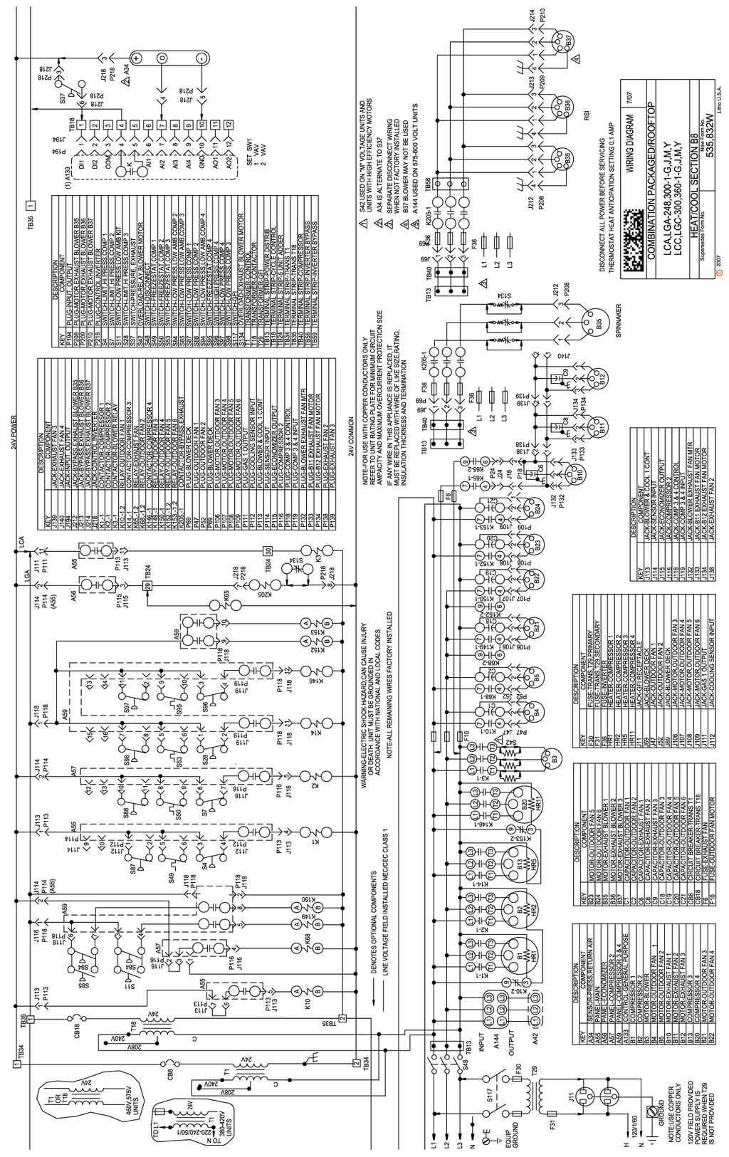
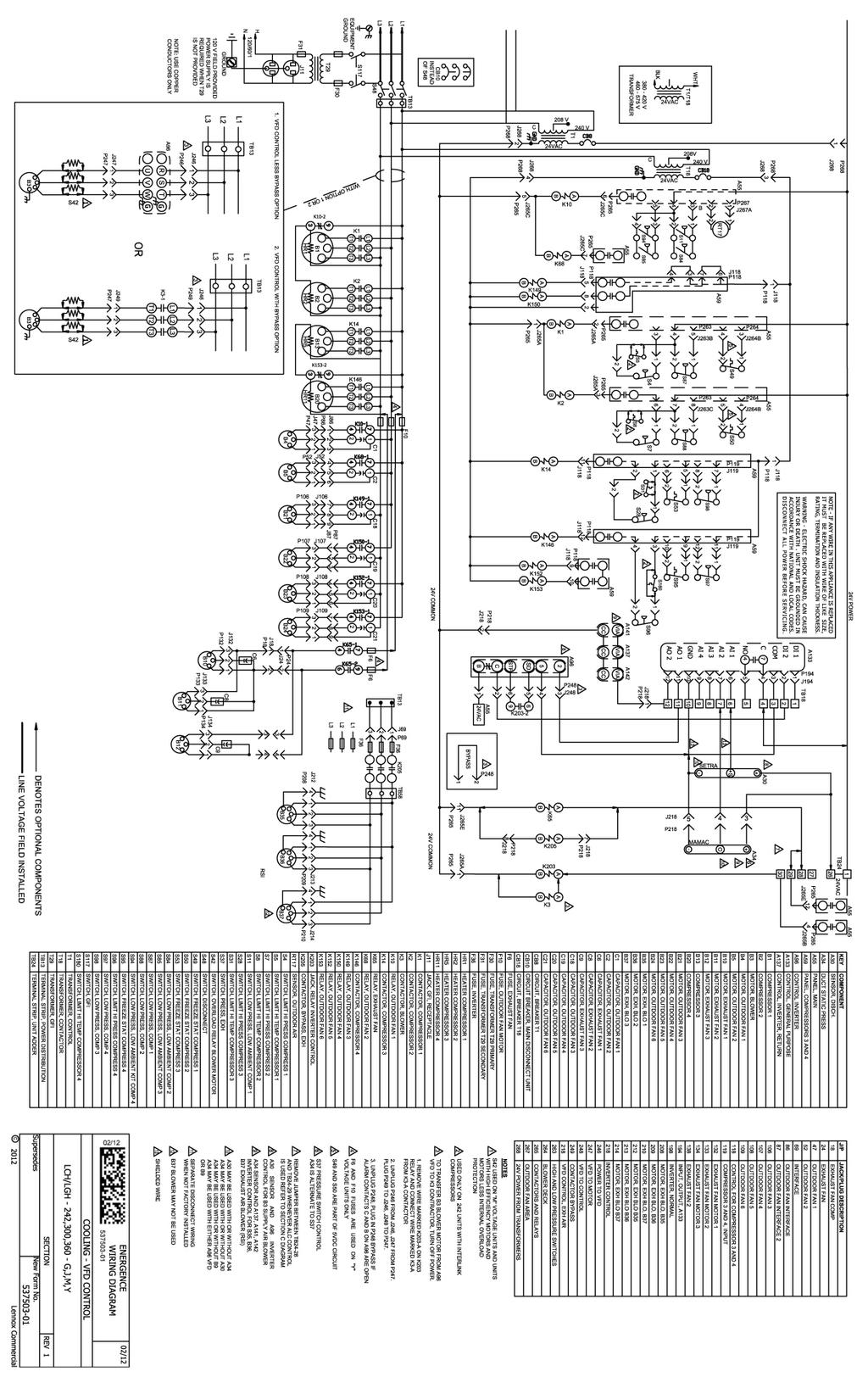
3 5. Install provided adapter panel using existing screws that were removed in Step 2. IN STALL POWER EX HAUST ASSEMBLY 1. Using lifting lugs, raise PEB/PEV unit approximately three (3) feet. Remove nut and bolt assembly to slide telescoping part of leg out of guide from the top. Reinsert leg into bottom of guide having attached flat foot under unit. Do not fasten tightly, adjustment will need to be made when PEB/PEV is put into position on unit. See Figure 6. Note - Equipment support kit or equivalent should be used under feet of standoff legs to prevent roof damage. 2. Apply ¾" x ¼" gasket material (provided in hardware bag) to open side of PEB/PEV on the turned out flanges of this unit. 3. Locate the connector P218 wiring harness in the PEB/PEV. See Figure 7. Route harness into the return air of the rooftop unit near J218. See Figure 2 and 4. These harnesses will be connected after the PEB/PEV is attached to rooftop unit. Refer to wiring diagram on Pages 8 thru Locate the connector P69 wiring harness in the PEB/PEV. Route harness into the return air of the rooftop unit near J69. Connect after power exhaust assembly is attached to rooftop unit. See Figure 8. Refer to wiring diagram in this instruction. 5. Position PEB/PEV in front of horizontal exhaust air opening. Line up the PEB/PEV to the rooftop unit. Insure that there are not any screws on the rooftop unit that will interfere with the mounting flanges of the PEB/PEV and if so remove them. 6. Lower PEB/PEV onto rooftop unit base rail catching the front edge of the PEB/PEV bottom. Slide the PEB/PEV so that it is tight against the adapter panel and top panel holes align with adapter panel holes. Now secure PEB/PEV top and side to the rooftop unit with supplied screws. See Figure With the PEB/PEV in place, adjust the standoff legs to level and support PEB/PEV against rooftop unit. Tighten securely. Release all the weight from lifting crane. Rotate lifting lug to original position and tighten machine bolts. See Figure 10 and Check and seal, if necessary, along the edges where the PEB/PEV meets the rooftop unit to ensure there is no air leakage. 9. Remove access panels and connect P69 to J69 and P218 to J218. a. PEV models, drop provided sensor tube into return air 10. Replace access panels onto the PEB/PEV unit and secure. 11- Restore power to unit. 12- Once PEB/PEV is working properly, caulk any open joints, holes, or seams to make the units completely air and water tight. 13- Leave this instruction manual in the pouch on the inside of the control compartment door on the Lennox rooftop unit. PAGE 3 J218 Figure 4 Figure 5 Figure 6 P218 Figure 7


4 BLOWER SPEED AD JUST MENT Note - To access motor sheaves for center blower assembly, top panel of power exhaust will need to be removed. Blower speed selection is accomplished by changing the sheave setting on exhaust air blowers. All blowers are factory set at open for minimum airflow. To determine air flow setting, measure the return duct static pressure and read CFM from table. Reference Tables. P69 PRES SURE TRANS DUC ERS WITH VDC OUT PUT Range (w.c.) 0 to 1.0 / 0 to 0.5 / 0 to 0.25 / -0.5 to / to / to Indicates Factory Setting Output 0-10 VDC Figure 8 Wiring Refer to PEB Power Exhaust unit diagram for detail connections. Tubing The high pressure tubing is coiled inside PEB/PEV and has a pressure tap on the end. This is 3 feet long and hangs inside the return air duct. Note: This tube may need to be replaced with a longer tube if specification calls for measuring room pressure. The low pressure tubing is factory mounted to the corner post of the PEB/PEV. Use flexible ¼" O.D. 5 32" I.D. tubing for the high and low pressure connections. Adjustments Figure 9 Figure 10 Figure 11 PAGE 4


 three phase blower motors are phased sequentially ensuring correct rotation and operation. If not go to Step 2.")
 to the PEB/PEV control box. See Figure 12. d. Replace PEB/PEV control access cover. e. Reapply power. 3. Set thermostat to normal operating position. 4.")

5 CAUTION Never connect 120 Vac to these transducers. Never connect AC voltage to a unit intended for DC supply. Check out 1. Verify that the unit is mounted in the correct position. 2. Verify appropriate input signal and supply voltage. 3. Verify appropriate configuration range. Trans ducer Op er a tion This is a rough functional check only. 1. Adjust the pressure by blowing into high pressure tube to obtain maximum output signal for appropriate range. 2. Output should be 10 Vdc. 3. Adjust the pressure by releasing pressure from high pressure tube to obtain minimum output signal. 4. Output should be 0 Vdc. Note - For applications requiring a high degree of accuracy, the use of laboratory quality meters and gauges are recommended. Figure 12 SYSTEM CHECK 1. Verify that the (3) three phase blower motors are phased sequentially ensuring correct rotation and operation. If not go to Step Disconnect main power to unit before making adjustment to PEB/PEV unit. a. Disconnect power. b. Remove PEB/PEV control access cover c. Reverse any two power leads (L1 and L2) to the PEB/PEV control box. See Figure 12. d. Replace PEB/PEV control access cover. e. Reapply power. 3. Set thermostat to normal operating position. 4. Restore power to unit. MAINTENANCE Motor Maintenance All motors use prelubricated sealed bearings; no further lubrication is necessary. Mechanical Inspection Make visual inspection of dampers, linkage assemblies and PEB/PEV rotating bearings during routine maintenance. To access blower pulley, belt and bearings for assembly behind control box. Remove (2) two screws on right side of box at the base. Then pivot box away from blower assembly. See Figure 13. Belt and Pulley Alignment Proper alignment is essential to maintain long V-Belt life. Belt alignment should be checked every time belt maintenance is performed, each time the belt is replaced, and whenever sheaves are removed or installed. Figure 13 Figure 14 Figure 15 PAGE 5
6 Belt Installation Always move the drive unit forward so the belt can be easily slipped into the groove without forcing them. Never force the belt into a sheave with a screw driver or wedge. You will damage the fabric and break the cords. It is recommended that the pulley center distances be offset by ¾" for proper length. This will allow the motor assembly to slide forward to remove belt and backward for belt tension. Belt Tension Belt Tension should be checked at least every 6 months, more frequently in some applications. Measure the span length (center distance between pulleys when belt is snug). Mark center of span, then apply a force (6 to 9 Lbs on new belts) perpendicular to the span large enough to deflect the belt 1 64" for every inch in span length. Variable Frequency Drive (VFD) To access VDF remove access door opposite control box. See Figure 14. These VFD are preprogrammed. A list of the parameters are listed on Page 14 of this instruction. For units that have bypass option, to switch to direct control from VFD control do the following steps. 1. Disconnect power at rooftop unit. 2. Remove access doors on each end. 3. Remove top panel of PEV. 4. Unplug each motor harness from wiring cap and connect to properly marked alternate cap. See Figure 15. Refer to wiring diagrams. 5. At control box remove jumper plug (J211) from top of box, and store inside control box. 6. Reattach top panel. 7. Place access doors back on each end of PEV. 8. Reconnect power at rooftop unit. PAGE 6
7 PAGE 7 High Static Power Ex haust Fans - 50% Unit contains: Motors /460 Volt, 2.0 HP, 3Ph, 1725 RPM, 50/60Hz, /3.3 FLA, 1.15 Service Factor, 56H Frame, Open Drip Proof, 7/8" x 2.31" shaft. Motors Volt, 2.0 HP, 3Ph, 1725 RPM, 50/60Hz, 2.4 FLA, 1.15 Service Factor, 56H Frame, Open Drip Proof, 7/8" x 2.31" shaft. Adjustable motor sheaves 3.25" dia.x 7 /8" bore, variable pitch (2.55 to 3.35), 5 turns. Blower pulley " dia. X 1" bore, fixed pitch (9.75). Adjustable motor sheaves 3.75" dia.x 7 /8" bore, variable pitch (2.65 to 3.65), 5 turns. Blower pulley " dia. X 1" bore, fixed pitch (7.75). Adjustable motor sheaves 4.75" dia.x 7 /8" bore, variable pitch (3.65 to 4.65), 5 turns. Blower pulley " dia. X 1" bore, fixed pitch (8.75). Data contains a 10% belt loss factor. E.S.P CFM RPM BHP RPM BHP RPM BHP RPM BHP RPM BHP RPM BHP RPM BHP RPM BHP RPM BHP RPM BHP RPM BHP xxxx xxxx High Static Power Ex haust Fans - 100% Unit contains: Motors /460 Volt, 2.0 HP, 3Ph, 1725 RPM, 50/60Hz, /3.3 FLA, 1.15 Service Factor, 56H Frame, Open Drip Proof, 7/8" x 2.31" shaft. Motors Volt, 2.0 HP, 3Ph, 1725 RPM, 50/60Hz, 2.4 FLA, 1.15 Service Factor, 56H Frame, Open Drip Proof, 7/8" x 2.31" shaft. Adjustable motor sheaves 3.25" dia.x 7 /8" bore, variable pitch (2.55 to 3.35), 5 turns. Blower pulley " dia. X 1" bore, fixed pitch (9.75). Adjustable motor sheaves 3.75" dia.x 7 /8" bore, variable pitch (2.65 to 3.65), 5 turns. Blower pulley " dia. X 1" bore, fixed pitch (7.75). Adjustable motor sheaves 4.75" dia.x 7 /8" bore, variable pitch (3.65 to 4.65), 5 turns. Blower pulley " dia. X 1" bore, fixed pitch (7.75). [Optional] Inverter - (3) Toshibia Inverters, Data contains a 10% belt loss factor. E.S.P CFM RPM BHP RPM BHP RPM BHP RPM BHP RPM BHP RPM BHP RPM BHP RPM BHP RPM BHP RPM BHP RPM BHP
8 PAGE 8
9 PAGE 9
10 PAGE 10
11 PAGE 11
12 PAGE 12
13 PAGE 13
14 PAGE 14
15 PAGE 15 Sequence For Entries Display On Panel COMM. NUM BER S11 Function INVERTER PARAMETER SETTINGS - S11 Series De fault S11 Set ting Required S11 1 F Parameter Changes 0 0 0=Permitted; 1=Prohibited Information 2 F Units Selection 0 1 Changes read out to amps and volts. (0=% or rated out put; 1=amps &volts.) 3 CnOd 0003 Command Mode 1 0 0=Term Brd (IMC / ex ter nal con trol ler), 1 = Op er a tion Panel 4 FnOd 0004 Freq. Setting Selection 0 1 0=Built in potentiometer, 1=VIA 5 ACC 0009 Acceleration Time (sec.) Seconds to Maximum Frequency 6 dec 0010 Deceleration Time (sec.) Sec onds From Max i mum Fre quency to stop 7 FH 0011 Max Fre quency (Hz) Maximum allowed Hz output 8 UL 0012 Up per limit Fre quency (Hz) Maximum recognized Hz command 9 LL 0013 Lower Freq Limit (Hz) Minimum Hz continuous operation 10 ul 0014 Base Fre quency (Hz) Mo tor de sign Hz as shown on mo tor nameplate 11 thr 0600 Electronic Motor Protection (A) 100._ Pro gram Mo tor FLA [as shown on mo tor nameplate] 12 F Auto Restart Selection 0 1 1=Re start mo tor af ter mo men tary power loss, 0=disabled 13 F Regenerative Ride-Through 0 1 1=Automatic setting, 0=Disabled. 14 F Re try Num ber of Times 0 4 Num ber of re start at tempts af ter an over load trip 15 F PWM Car rier Fre quency (khz) Ad just ment Range is 2.0 khz khz 16 F Parameter Changes 0 1 0=Permitted; 1=Prohibited
16 NOTES PAGE 16
Package Unit Modulating Economizer Installation Instructions
 Package Unit Modulating Economizer Installation Instructions Downflow Unit Warning: Recognize this symbol as an indication of Important Safety Information! Read all instructions prior to installation.
Package Unit Modulating Economizer Installation Instructions
 Package Unit Modulating Economizer Installation Instructions Downflow Unit Warning: Recognize this symbol as an indication of Important Safety Information! Read all instructions prior to installation.
INSTALLATION INSTRUCTIONS FOR ENERGY RECOVERY VENTILATOR (FIXED) USED WITH TRANE ROOFTOP UNIT MODELS YCD/TCD 15 TO 20 TON UNITS
 USED WITH TRANE ROOFTOP UNIT MODELS YCD/TCD 15 TO 20 TON UNITS") INSTALLATION INSTRUCTIONS R20A-10TDW MAY 11, 2005 SUPERCEDES: 06-23-03 ENERGY RECOVERY VENTILATOR INSTALLATION INSTRUCTIONS FOR ENERGY RECOVERY VENTILATOR (FIXED) USED WITH TRANE ROOFTOP UNIT MODELS YCD/TCD
INSTALLATION INSTRUCTIONS R20A-10TDW MAY 11, 2005 SUPERCEDES: 06-23-03 ENERGY RECOVERY VENTILATOR INSTALLATION INSTRUCTIONS FOR ENERGY RECOVERY VENTILATOR (FIXED) USED WITH TRANE ROOFTOP UNIT MODELS YCD/TCD
ENERGY RECOVERY WHEEL
 INSTALLATION INSTRUCTIONS FORM RZ-NA-I-XCWU28-PVT MARCH 29, 2005 SUPERCEDES 09-15-04 P28A-03ZDW ENERGY RECOVERY WHEEL IN STAL LA TION IN STRUC TIONS FOR 1,500-2,800 CFM OUT OUT SIDE AIR EN ERGY RE COV
ENERGY RECOVERY WHEEL
 INSTALLATION INSTRUCTIONS FORM RZ-NA-I-XCWU11-PVT MARCH 29, 2005 SUPERCEDES 02-01-05 P11A-03ZDW ENERGY RECOVERY WHEEL IN STAL LA TION IN STRUC TIONS FOR 600-1,000 CFM OUT OUT SIDE AIR EN ERGY RE COV ERY
INSTALLATION INSTRUCTIONS
 INSTALLATION INSTRUCTIONS MAXA-MI$ER UNITARY ENERGY RECOVERY VENTILATOR MODEL VR028A15M/H & VR028A25H (STATIONARY) 035-19268-002-A-0709 / R28A-18YDW Energy recovery COMPONENT certified to the AHRI Air-to-Air
COMMERICAL SPLIT SYSTEM KITS AND ACCESSORIES /2014 Supersedes 8/2012
 COMMERICAL SPLIT SYSTEM KITS AND ACCESSORIES 506953-01 3/2014 Supersedes 8/2012 Litho U.S.A. MSAV Supply Air Blower VFD Kit INSTALLATION INSTRUCTIONS FOR MSAV (MULTI-STAGE AIR VOLUME) SUPPLY AIR BLOWER
INSTALLATION INSTRUCTIONS
 FOR 3 THRU 12.5 TON SINGLE PACKAGE EQUIPMENT General The instruction provides all the necessary information to properly field install this economizer on the above indicated equipment. Economizer Model
ENERGY RECOVERY WHEEL
 ENERGY RECOVERY WHEEL INSTALLATION INSTRUCTIONS P28A-13RDW DECEMBER 19, 2013 SUPERSEDES 12-08-03 INSTALLATION INSTRUCTIONS FOR ENERGY RECOVERY VENTILATOR (PIVOTING) USED WITH RHEEM UNIT MODELS 7 ½ TO 12
INSTALLATION INSTRUCTIONS FOR ENERGY RECOVERY VENTILATOR (FIXED) USED WITH TRANE ROOFTOP UNIT MODELS YCD/TCD 15 TO 20 TON UNITS
 USED WITH TRANE ROOFTOP UNIT MODELS YCD/TCD 15 TO 20 TON UNITS") INSTALLATION INSTRUCTIONS R28A-10TDW MAY 2, 2005 ENERGY RECOVERY VENTILATOR INSTALLATION INSTRUCTIONS FOR ENERGY RECOVERY VENTILATOR (FIXED) USED WITH TRANE ROOFTOP UNIT MODELS YCD/TCD 15 TO 20 TON UNITS
INSTALLATION INSTRUCTIONS R28A-10TDW MAY 2, 2005 ENERGY RECOVERY VENTILATOR INSTALLATION INSTRUCTIONS FOR ENERGY RECOVERY VENTILATOR (FIXED) USED WITH TRANE ROOFTOP UNIT MODELS YCD/TCD 15 TO 20 TON UNITS
INSTALLATION INSTRUCTIONS FOR ENERGY RECOVERY VENTILATOR (FIXED) USED WITH GOODMAN ROOFTOP UNIT MODELS 7 ½ TO 12 ½ TON UNITS
 USED WITH GOODMAN ROOFTOP UNIT MODELS 7 ½ TO 12 ½ TON UNITS") INSTALLATION INSTRUCTIONS R20A-10GDW SEPTEMBER 21, 2015 ENERGY RECOVERY VENTILATOR INSTALLATION INSTRUCTIONS FOR ENERGY RECOVERY VENTILATOR (FIXED) USED WITH GOODMAN ROOFTOP UNIT MODELS 7 ½ TO 12 ½ TON
INSTALLATION INSTRUCTIONS R20A-10GDW SEPTEMBER 21, 2015 ENERGY RECOVERY VENTILATOR INSTALLATION INSTRUCTIONS FOR ENERGY RECOVERY VENTILATOR (FIXED) USED WITH GOODMAN ROOFTOP UNIT MODELS 7 ½ TO 12 ½ TON
STAND ALONE ERV S-SERIES
 STAND ALONE ERV S-SERIES INSTALLATION INSTRUCTIONS SXX-2ERV AUGUST 16, 2013 SUPERCEDES 10-30-06 ENERGY RECOVERY VENTILATOR SERIES S11, S20, S28, S36, S46 & S62 INSTALLATION INSTRUCTIONS FOR ENERGY RECOVERY
INSTALLATION INSTRUCTIONS
 MiniCOREVentilator ENERGY RECOVERY CORE INSTALLATION INSTRUCTIONS MC500-1ERV JANUARY 10, 2018 SUPERSEDES: NONE INSTALLATION INSTRUCTIONS FOR MINICORE VENTILATOR (MCV) WITH FACTORY INSTALLED OPTIONS USED
INSTALLATION INSTRUCTIONS
 FOR 3 THRU 12.5 TON SINGLE PACKAGE EQUIPMENT General The instruction provides all the necessary information to properly field install this economizer on the above indicated equipment. Economizer Model
 POWER EXHAUST START UP PRE START UP ONCE THE POWER EXHAUST ECONOMIZER IS INSTALLED, REMOVE THE ACCESS DOORS ON THE EXHAUST CABINET. ROUTE LINE VOLTAGE CABLE FROM THE VFD TO THE DISCONNECT OR UNIT POWER
INSTALLATION INSTRUCTIONS FOR ROOFTOP STAND ALONE ENERGY RECOVERY UNIT IN SIDE BY SIDE DESIGN
 INSTALLATION INSTRUCTIONS FORM RZ-NA-I-XBWS-AQ20 MAY 29, 2014 SUPERCEDES 09-27-13 SXX-2ZERV ENERGY RECOVERY VENTILATOR Applies To Model XBWS When Used With Option AQ20 Side By Side Design INSTALLATION
START-UP CHECKLIST. Date: Job Name: Customer Name: Address: City: State: Zip: Model Number: Serial Number: Qualified Start-up Technician:
 START-UP INSTRUCTION OPTIMUM 36000 To 72000 BTU S PACKAGE UNITS 3 To 6 Ton START-UP CHECKLIST Date: Job Name: Customer Name: Address: City: State: Zip: Model Number: Serial Number: Qualified Start-up Technician:
INSTALLATION INSTRUCTIONS FOR ROOFTOP STAND ALONE ENERGY RECOVERY UNIT IN VERTICAL (UP/DOWN) AIRFLOW DESIGN
 AIRFLOW DESIGN") INSTALLATION INSTRUCTIONS FORM RZ-NA-I-XBWS-AQ21 MAY 29, 2014 SUPERCEDES 09-27-13 DXX-2ZERV ENERGY RECOVERY VENTILATOR Applies to Model XBWS when used with Option AQ21 Vertical Supply and Return Air INSTALLATION
INSTALLATION INSTRUCTIONS FORM RZ-NA-I-XBWS-AQ21 MAY 29, 2014 SUPERCEDES 09-27-13 DXX-2ZERV ENERGY RECOVERY VENTILATOR Applies to Model XBWS when used with Option AQ21 Vertical Supply and Return Air INSTALLATION
INSTALLATION INSTRUCTIONS
 FOR 6.5 THRU 12.5 TON SINGLE PACKAGE EQUIPMENT MODEL AIR CONDITIONERS Gen eral The instruction provides all the necessary information to properly field install this economizer on the above indicated equipment.
START-UP CHECKLIST. Date: Job Name: Customer Name: Address: City: State: Zip: Model Number: Serial Number: Qualified Start-up Technician:
 START-UP INSTRUCTION START-UP CHECKLIST SERIES 5 36000 To 72000 BTU S PACKAGE UNITS 3 To 6 Ton Date: _ Job Name: Customer Name: Address: City: State: Zip: Model Number: Serial Number: Qualified Start-up
AUXILIARY ELECTRIC HEATER KITS FOR 7.5, 10, 15 AND 20 TON COMMERCIAL AIR HANDLERS RXHE-CE, DE
 AUXILIARY ELECTRIC HEATER KITS FOR 7., 10, 1 AND 20 TON COMMERCIAL AIR HANDLERS RXHE-CE, DE WARNING: THIS ACCESSORY IS TO BE INSTALLED BY A QUALIFIED, LICENSED SERVICE PERSON. TO AVOID UN - SATISFACTORY
INSTALLATION INSTRUCTION
 FORM# 609A-0808 (609A-0298) I - SHIP PING AND PACK ING LIST Package 1 of 1 contains: 1 - Economizer Assembly 1 - Fresh Air Hood w/ Filter 1 - Control Package 1 - Barometric Relief Hood 1 - Filter Access
STAND ALONE ERV M-SERIES
 STAND ALONE ERV M-SERIES INSTALLATION INSTRUCTIONS MXX-2ERV AUGUST 16, 2013 SUPERCEDES 10-26-06 ENERGY RECOVERY VENTILATOR SERIES M11, M20, M28, M36, M46 & M62 INSTALLATION INSTRUCTIONS FOR ENERGY RECOVERY
STAND ALONE ERV O-SERIES
 STAND ALONE ERV O-SERIES INSTALLATION INSTRUCTIONS OXX-2ERV AUGUST 19, 2013 SUPERCEDES 10-30-06 ENERGY RECOVERY VENTILATOR SERIES O11, O20, O28, O36, O46 & O62 INSTALLATION INSTRUCTIONS FOR ENERGY RECOVERY
Installation Instructions
 H068A00 H069A00 H070A00 POWER EXHAUST ACCESSORY SINGLE PACKAGE ROOFTOP UNITS 12.5to25TONS Installation Instructions TABLE OF CONTENTS SAFETY CONSIDERATIONS... 1 GENERAL... 1 INSTALLATION... 2 Power Exhaust
Installation Instructions
 CRPWREXH08A0, CRPWREXH09A0, CRPWREXH08A00, CRPWREXH08A00 For Use With Horizontal EconoMi$er IV, EconoMi$er, or EconoMi$er X (W70) Installation Instructions TABLE OF CONTENTS PACKAGE CONTENTS... PACKAGE
Installation Instructions
 010A00 011A00 014A00 SMALL ROOFTOP UNITS TWO POSITION OUTDOOR AIR DAMPER 2to15TONS (50/60 Hz) Installation Instructions TABLE OF CONTENTS PACKAGE CONTENTS... 1 PACKAGE USAGE... 1 SAFETY CONSIDERATIONS...
Installation Instructions
 08A0, 09A0, 08A00, 08A00 For Use With Horizontal EconoMi$ert IV or EconoMi$ert Only SMALL ROOFTOP UNITS ACCESSORY HORIZONTAL EXHAUST GAS HEATING/ELECTRIC COOLING, ELECTRIC COOLING, AND HEAT PUMP UNITS
ECONOMIZERS. 1/2012 Supersedes
 ECONOMIZERS Litho U.S.A. 2012 506948 01 1/2012 Supersedes 506394 01 K1ECON20C 1 ECONOMIZERS INSTALLATION INSTRUCTIONS FOR ECONOMIZER AND OUTDOOR AIR (604592 03; 54W77) USED WITH KG/KC/KH 180 300S UNITS
ACCESSORY KIT INSTALLATION INSTRUCTIONS
 ACCESSORY KIT INSTALLATION INSTRUCTIONS ECONOMIZER DAMPER AND HOOD MOD ELS 2EE04707924 / 2EE04708024 1EH0417 / 1EH0418 FOR 15, 17.5, 20, AND 25 TON ROOF TOP UNITS Gen eral This instruction provides the
STAND ALONE ERV D-SERIES
 STAND ALONE ERV D-SERIES INSTALLATION INSTRUCTIONS DXX-2ERV OCTOBER 6, 2015 SUPERCEDES 10-29-14 ENERGY RECOVERY VENTILATOR SERIES D11, D20, D28, D36, D46, D62, D80 & D12 INSTALLATION INSTRUCTIONS FOR ENERGY
INSTALLATION VARIABLE FREQUENCY DRIVE THREE PHASE ALX SERIES SPUN ALUMINUM EXHAUSTERS
 SPUN ALUMINUM EXHAUSTER OPERATION INSTRUCTIONS AND PARTS MANUAL READ AND SAVE THESE INSTRUCTIONS The purpose of this manual is to aid in the proper installation and operation of the blowers. These instructions
INSTALLATION INSTRUCTIONS FOR ENERGY RECOVERY VENTILATOR (PIVOTING) USED WITH GOODMAN ROOFTOP UNIT MODELS 2 TO 5 TON UNITS
 USED WITH GOODMAN ROOFTOP UNIT MODELS 2 TO 5 TON UNITS") INSTALLATION INSTRUCTIONS P11A-09GDW OCTOBER 7, 2011 SUPERSEDES 06-07-11 ENERGY RECOVERY VENTILATOR INSTALLATION INSTRUCTIONS FOR ENERGY RECOVERY VENTILATOR (PIVOTING) USED WITH GOODMAN ROOFTOP UNIT MODELS
INSTALLATION INSTRUCTIONS P11A-09GDW OCTOBER 7, 2011 SUPERSEDES 06-07-11 ENERGY RECOVERY VENTILATOR INSTALLATION INSTRUCTIONS FOR ENERGY RECOVERY VENTILATOR (PIVOTING) USED WITH GOODMAN ROOFTOP UNIT MODELS
Installation Instructions
 CRPWREXH068A00 CRPWREXH069A00 CRPWREXH070A00 POWER EXHAUST ACCESSORY SINGLE PACKAGE ROOFTOP UNITS 15 to 25 TONS Installation Instructions TABLE OF CONTENTS SAFETY CONSIDERATIONS... 1 GENERAL... 1 INSTALLATION...
Installation Instructions
 00A0, 0A0-0A0 080A00 08A00 For Use With Vertical EconoMi$ert IV or EconoMi$ert Only SMALL ROOFTOP UNITS ACCESSORY VERTICAL EXHAUST GAS HEATING/ELECTRIC COOLING, ELECTRIC COOLING, AND HEAT PUMP UNITS TO5TON
Factory Option Codes L M E S P R D V F F H E
 I N D O O R A I R Q U A L I T Y P R O D U C T S P E C I F I C AT I O N S ENERGY RECOVERY SYSTEM FOR L-SERIES ROOFTOP UNITS - 60 HZ Bulletin No. 10533 January 011 Supersedes October 010 800 to 600 cfm Capacity
INSTALLATION INSTRUCTIONS COMMERCIAL ROOM VENTILATORS WITH EXHAUST
 INSTALLATION INSTRUCTIONS COMMERCIAL ROOM VENTILATORS WITH EXHAUST MODEL CRVMP-5 For Use with Bard 3 through 5 Ton Wall Mount Air Conditioners and Heat Pumps Bard Manufacturing Company Bryan, Ohio 43506
ENERGY RECOVERY SYSTEM 60 HZ
 I N D O O R A I R Q U A L I T Y E N G I N E E R I N G D A T A ENERGY RECOVERY SYSTEM 60 HZ Bulletin No. 210517 April 2008 Supersedes 210368 April 2007 300 to 6200 cfm Capacity MODEL NUMBER IDENTIFICATION
Installation Instructions
 Installation Instructions Power Exhaust Part Numbers: CRPWREXH07A00 THROUGH CRPWREXH079A00 Conversion Package Numbers: CRPECONV005A00, CRPECONV006A00 CONTENTS Page SAFETY CONSIDERATIONS......................
Advantage Fan 36" and 48"
 R R Advantage Fan 36" and 48" AT36Z AT365Z AT481Z AT4815Z Page 1 of 12 Section USER'S MANUAL and INSTALLATION GUIDE TABLE OF CONTENTS Parts list... 3 Installation... 4 Electrical Wiring... 6 Operation...
INSTALLATION INSTRUCTIONS
 2005 Lennox Industries Inc. Dallas, Texas, USA INSTALLATION INSTRUCTIONS CB29M & CB30M Elite Series Units MULTI POSITION BLOWER COILS 504,79M 09/05 Supersedes 04/05 Litho U.S.A. RETAIN THESE INSTRUCTIONS
ECONOMIZERS. 5/2012 Supersedes
 Litho U.S.A. 2012 ECONOMIZERS 507031 01 5/2012 Supersedes 506747 01 K1ECON ECONOMIZERS INSTALLATION INSTRUCTIONS FOR ECONOMIZERS AND OUTDOOR AIR HOODS USED WITH KG/KC/KH 024, 030, 036, 048, 060, 072, 090
CAUTION Danger of sharp metallic edges. Can cause injury. Take care when servicing unit to avoid accidental contact with sharp edges.
 OUTDOOR AIR S Litho U.S.A. 507214-01 2014 12/2014 Supersedes 9/2013 OUTDOOR AIR S INSTALLATION INSTRUCTIONS FOR OUTDOOR AIR S AND OUTDOOR AIR USED WITH 156-300S UNITS Shipping and Packing List Package
INSTALLATION INSTRUCTIONS ISLAND RANGE HOOD
 Read and Save These Instructions All Hoods Must Be Installed By A Qualified Installer INSTALLATION INSTRUCTIONS ISLAND RANGE HOOD Read All Instructions Thoroughly Before Beginning Installation WARNING
CPG Series. Submittal Data Form. 3- to 6-Ton Self-Contained. Packaged Gas/Electric. with R-410A
 CPG Series 3- to 6-Ton Self-Contained Submittal Data Form Purchaser Order No. Engineer Unit No. Model No. Unit Designation Performance Data Certified By: Packaged Gas/Electric with R-410A Standard Features
TECHNICAL GUIDE GENERAL SPECIFICATIONS COMMERCIAL SPLIT-SYSTEM COOLING UNITS FOUR PIPE SYSTEM OUTDOOR UNIT:
 036-21323-001-B-0202 GENERAL SPECIFICATIONS OUTDOOR UNIT: Two independent refrigerant circuits Inherently protected fan motors Two independent scroll compressors V-Coil Design Exterior service port connections
Blank-off. HVAC unit screws. Spacer for 1" filter ILL. 3. Screw
 ICP INSTALLATION INSTRUCTIONS for NPECOMZR00A00 ICP's economizer is convertible-it will work in either a down discharge or horizontal discharge application. Read these instructions completely and carefully
INSTALLATION INSTRUCTIONS EUROLINE/EUROLINE PRO ISLAND RANGE HOOD
 Read and Save These Instructions All Hoods Must Be Installed By A Qualified Installer INSTALLATION INSTRUCTIONS EUROLINE/EUROLINE PRO ISLAND RANGE HOOD Read All Instructions Thoroughly Before Beginning
LIGHT COMMERCIAL - 3 HP ECM MOTOR / CONTROLLER HIGH STATIC DRIVE KITS
 LIGHT COMMERCIAL - 3 HP ECM MOTOR / CONTROLLER HIGH STATIC DRIVE KITS INSTALLATION INSTRUCTIONS For R7TQ/P7TQ/Q7TQ -090 (T) and -120 (T) Series Single Package Rooftop Units IMPORTANT ATTENTION INSTALLERS:
Installation Instructions Electric Heaters 5 20 kw
 Small Packaged Products 2 to 5 Tons Accessory Electric Heaters Cancels: IIK 564A-24-2 IIK 564A-24- -02 Installation Instructions Electric Heaters 5 20 kw NOTE: Read the entire instruction manual before
2520- EC Motor Speed Controller
 2520- EC Motor Speed Controller T1 AC Line Voltage From Contactor T2 or Neutral 760-ECM ECM Motor BLACK ORANGE BLACK RED (+) Signal 24VAC (-) GND Features Motor Types: ECM (dc brushless) Motors Motor Speed:
CRECOMZR054B00 CRECOMZR055B00. VERTICAL AND HORIZONTAL ECONOMI$ER2 ACCESSORY MEDIUM ROOFTOP UNITS 15 to 27 1/2 TONS WARNING TABLE OF CONTENTS
 CRECOMZR05B00 CRECOMZR055B00 VERTICAL AND HORIZONTAL ECONOMI$ER2 ACCESSORY MEDIUM ROOFTOP UNITS 15 to 27 1/2 TONS TABLE OF CONTENTS PACKAGE USAGE...1 SAFETY CONSIDERATIONS...1 PACKAGE CONTENTS...1 GENERAL...2
ERV ENERGY RECOVERY VENTILATOR 60 HZ. Indoor / Outdoor 500 to 10,000 cfm Capacity ERV I - D - D - P - 1 MODEL NUMBER IDENTIFICATION
 P R O D U C T S P E C I F I C AT I O N S I N D O O R A I R Q U A L I T Y ERV ENERGY RECOVERY VENTILATOR 60 HZ Bulletin No. 20245 March 200 Supersedes April 2009 Indoor / Outdoor 500 to 0,000 cfm Capacity
READ AND SAVE THESE INSTRUCTIONS
 READ AND SAVE THESE INSTRUCTIONS Part #469003 Model Vektor -H Installation Operation and Maintenance Manual for Vektor-H Laboratory Exhaust System Receiving Greenheck model Vektor-H fans are thoroughly
Corp L3 Revised CB17/CBH17 SERIES UNITS SPECIFICATIONS CB17-95V CBH17-95V
 Service Literature Corp. 0002 L3 Revised 08 2004 CB17/CBH17 SERIES UNITS CB17 Lennox CB17 and CBH17 model blower coil units, designed for indoor applications only, are available in two models; CB17 series
INSTALLATION INSTRUCTIONS MODELS (-)XRD-MCCM3 & (-)XRD-MECM3/TECM3 CONVERTIBLE AIRFLOW ECONOMIZERS
XRD-MCCM3 & (-)XRD-MECM3/TECM3 CONVERTIBLE AIRFLOW ECONOMIZERS") INSTALLATION INSTRUCTIONS MODELS (-)XRD-MCCM3 & (-)XRD-MECM3/TECM3 CONVERTIBLE AIRFLOW ECOMIZERS WARNING THIS ACCESSORY IS TO BE INSTALLED BY A QUALIFIED, LICENSED SERVICE PERSON. TO AVOID UNSATISFACTORY
INSTALLATION INSTRUCTIONS MODELS (-)XRD-MCCM3 & (-)XRD-MECM3/TECM3 CONVERTIBLE AIRFLOW ECOMIZERS WARNING THIS ACCESSORY IS TO BE INSTALLED BY A QUALIFIED, LICENSED SERVICE PERSON. TO AVOID UNSATISFACTORY
TABLE OF CONTENTS SPECIFICATIONS 3 INSTALLATION 4. Direct Mount 4. Ducted Installations 5. Installing Plenum 5. Machine Mount Stand 5.
 TABLE OF CONTENTS PAGE SPECIFICATIONS 3 INSTALLATION 4 Direct Mount 4 Ducted Installations 5 Installing Plenum 5 Machine Mount Stand 5 Ceiling Mount 6 Pedestal Stand 7 Drain Installation 7 Electrical 8
INSTALLATION INSTRUCTIONS EUROLINE/EUROLINE PRO WALL MOUNT HOOD
 Read and Save These Instructions All Hoods Must Be Installed By A Qualified Installer INSTALLATION INSTRUCTIONS EUROLINE/EUROLINE PRO WALL MOUNT HOOD Read All Instructions Thoroughly Before Beginning Installation
ELITE SERIES R-410A Ready - Multi-Position
 PRODUCT SPECIFICATIONS AIR HANDLERS CBXM ELITE SERIES R-0A Ready - Multi-Position Bulletin No. 0 October 07 Supersedes June 0 Nominal Capacity -. to Tons Optional Electric Heat -. to 0 kw MODEL NUMBER
Screw. (Note 4) Spacer for 1" filter ILL. 3. Screw
 Spacer for 1 filter ILL. 3. Screw") ICP INSTALLATION INSTRUCTIONS for (NPECOMZR006A00) ICP's economizer is convertible-it will work in either a down discharge or horizontal discharge application. Read these instructions completely and carefully
ICP INSTALLATION INSTRUCTIONS for (NPECOMZR006A00) ICP's economizer is convertible-it will work in either a down discharge or horizontal discharge application. Read these instructions completely and carefully
Power Roof Ventilator Installation, Operation, and Maintenance Manual. Down-blast Centrifugal Fan Utility Set Axial Fan
 Power Roof Ventilator Installation, Operation, and Maintenance Manual Up-blast Centrifugal Curb Mount Utility Set Up-blast Centrifugal Fan Down-blast Centrifugal Fan Utility Set Axial Fan RECEIVING AND
CPC Series. Submittal Data Form. 15- & 20-Ton Self-Contained. Packaged Air Conditioner. with R-410A
 CPC Series 15- & 20-Ton Self-Contained Submittal Data Form Job Name Purchaser Order No. Engineer Unit No. Model No. Unit Designation Performance Data Certified By: Packaged Air Conditioner with R-410A
CH5000 Heat Recovery Ventilator
 ADVANCED COMMERCIAL Heat Recovery Ventilator PRODUCT SPECIFICATIONS & TECHNICAL DATA Features NOMINAL CAPACITY 3500-5500 CFM CASING Double-wall cabinet White exterior paint, 22-gauge galvanized steel -gauge
Installation Instructions Electric Heaters 5 20 kw
 Small Packaged Products to 5 Tons Accessory Electric Heaters Cancels: IIK 564A--1 IIK 564A-- 11-01 Installation Instructions Electric Heaters 5 0 kw NOTE: Read the entire instruction manual before starting
READ AND SAVE THESE INSTRUCTIONS. Centrifugal Downblast Exhaust Fan Belt Driven for Roof & Wall Mounting
 READ AND SAVE THESE INSTRUCTIONS INSTALLATION, OPERATING INSTRUCTIONS & PARTS MANUAL Centrifugal Downblast Exhaust Fan Belt Driven for Roof & Wall Mounting Electrical wiring and connections should be done
PCB COMMERCIAL SERIES
 PCB COMMERCIAL SERIES 50 Hz SELF-CONTAINED PACKAGE CONDITIONER 7½, 0, AND 5 TON [6.4 kw to 5.8 kw] COOLING CAPACITY: 90,000 TO 80,000 BTU/H The PCB Commercial 50 Hz self-contained packaged air conditioner
UL/NEMA Type 1 & Type 12 FRENIC-HVAC Combination VFD
 UL/NEMA Type 1 & Type 12 FRENIC-HVAC Combination VFD Safety Precautions Read this manual thoroughly before proceeding with installation, connections (wiring), or maintenance and inspection. Ensure you
INSTALLATION INSTRUCTIONS MODELS (-)XRD-RGCM3 HORIZONTAL AIRFLOW ECONOMIZERS
XRD-RGCM3 HORIZONTAL AIRFLOW ECONOMIZERS") INSTALLATION INSTRUCTIONS MODELS (-)XRD-RGCM3 HORIZONTAL AIRFLOW ECOMIZERS WARNING THIS ACCESSORY IS TO BE INSTALLED BY A QUALIFIED, LICENSED SERVICE PERSON. TO AVOID UNSATISFACTORY OPERATION OR DAMAGE
INSTALLATION INSTRUCTIONS MODELS (-)XRD-RGCM3 HORIZONTAL AIRFLOW ECOMIZERS WARNING THIS ACCESSORY IS TO BE INSTALLED BY A QUALIFIED, LICENSED SERVICE PERSON. TO AVOID UNSATISFACTORY OPERATION OR DAMAGE
SPLIT-SYSTEM EVAPORATOR BLOWER DESCRIPTION ACCESSORIES EER 8.5 ARI RATINGS* K2ES120A25 10 NOMINAL TONS WITH TWO 5 TON CIRCUITS
 550.13-TG11Y (0500) SPLIT-SYSTEM EVAPORATOR BLOWER K2ES120A25 10 NOMINAL TONS WITH TWO 5 TON CIRCUITS EER 8.5 DESCRIPTION This completely assembled dual circuit evaporator blower includes a well-insulated
INSTALLATION INSTRUCTIONS COMMERCIAL ROOM VENTILATORS WITH EXHAUST. For Use with Bard CH Series 3, 4, & 5 Ton Wall Mount Heat Pumps
 INSTALLATION INSTRUCTIONS COMMERCIAL ROOM VENTILATORS WITH EXHAUST MODEL CHCRV-5 For Use with Bard CH Series 3, 4, & 5 Ton Wall Mount Heat Pumps Bard Manufacturing Company, Inc. Bryan, Ohio 43506 Since
SUNLINE 2000 SINGLE PACKAGE AIR - TO - AIR HEAT PUMPS DESCRIPTION. B1CH 180 & and 20 NOMINAL TONS ( EER)
") 511.06-TG3Y (0600) SINGLE PACKAGE AIR - TO - AIR HEAT PUMPS B1CH 1 & 40 15 and 0 NOMINAL TONS (8.5-8.8 EER) SUNLINE 000 DESCRIPTION York Sunline 000 Heat Pumps are convertible single package units. All
511.06-TG3Y (0600) SINGLE PACKAGE AIR - TO - AIR HEAT PUMPS B1CH 1 & 40 15 and 0 NOMINAL TONS (8.5-8.8 EER) SUNLINE 000 DESCRIPTION York Sunline 000 Heat Pumps are convertible single package units. All
INSTALLATION INSTRUCTIONS EUROLINE/EUROLINE PRO ISLAND RANGE HOOD
 WARNING - TO REDUCE THE RISK OF FIRE, USE ONLY METAL DUCTWORK C U L R Read and Save These Instructions All Hoods Must Be Installed By A Qualified Installer INSTALLATION INSTRUCTIONS EUROLINE/EUROLINE PRO
INSTALLATION INSTRUCTIONS EUROLINE/EUROLINE PRO WALL MOUNT HOOD
 WARNING - TO REDUCE THE RISK OF FIRE, USE ONLY METAL DUCTWORK C U L R Read and Save These Instructions All Hoods Must Be Installed By A Qualified Installer INSTALLATION INSTRUCTIONS EUROLINE/EUROLINE PRO
INSTRUCTIONS FOR (-)XRX-AW04 or (-)XRX-AW05 MOTORIZED FRESH AIR DAMPER KIT
XRX-AW04 or (-)XRX-AW05 MOTORIZED FRESH AIR DAMPER KIT") INSTRUCTIONS FOR (-)XRX-AW04 or (-)XRX-AW05 MOTORIZED FRESH AIR DAMPER KIT WARNING Recognize this symbol as an indication of Important Safety Information! THESE INSTRUCTIONS ARE INTENDED AS AN AID TO QUALIFIED
INSTRUCTIONS FOR (-)XRX-AW04 or (-)XRX-AW05 MOTORIZED FRESH AIR DAMPER KIT WARNING Recognize this symbol as an indication of Important Safety Information! THESE INSTRUCTIONS ARE INTENDED AS AN AID TO QUALIFIED
READ AND SAVE THESE INSTRUCTIONS. High Velocity Restaurant-Duty Utility Set Belt Driven for Roof Mounting
 READ AND SAVE THESE INSTRUCTIONS INSTALLATION, OPERATING INSTRUCTIONS & PARTS MANUAL High Velocity Restaurant-Duty Utility Set Belt Driven for Roof Mounting Electrical wiring and connections should be
INSTALLATION INSTRUCTIONS ISLAND RANGE HOOD
 Read and Save These Instructions All Hoods Must Be Installed By A Qualified Installer INSTALLATION INSTRUCTIONS ISLAND RANGE HOOD Read All Instructions Thoroughly Before Beginning Installation WARNING
Electric Coil [Make-Up Air / Displacement Ventilation / Space Heating] System
![Electric Coil [Make-Up Air / Displacement Ventilation / Space Heating] System](/thumbs/89/99847795.jpg "Electric Coil [Make-Up Air / Displacement Ventilation / Space Heating] System") V-Series (rev. 08/17/10) Electric Coil [Make-Up Air / Displacement Ventilation / Space Heating] System Note: Optional items and/or items requiring a choice, are shown between brackets and/or parentheses
V-Series (rev. 08/17/10) Electric Coil [Make-Up Air / Displacement Ventilation / Space Heating] System Note: Optional items and/or items requiring a choice, are shown between brackets and/or parentheses
EconoMi$er, Power Exhaust, and Sensor Installation Instructions
 Small Rooftop Units Gas Heating/Electric Cooling, Electric Cooling, and Heat Pump Units 3 to.5 Tons (50/60 Hz) EconoMi$er Package for Vertical and Horizontal Duct Systems Issue Date /0/0 EconoMi$er, Power
INSTALLATION INSTRUCTIONS EUROLINE/EUROLINE PRO WALL MOUNT HOOD
 WARNING - TO REDUCE THE RISK OF FIRE, USE ONLY METAL DUCTWORK C U L R Read and Save These Instructions All Hoods Must Be Installed By A Qualified Installer INSTALLATION INSTRUCTIONS EUROLINE/EUROLINE PRO
Electronically Commutated Motor Wiring Manual
 Electronically Commutated Motor Wiring Manual Table of Contents Safety Considerations 3 Application Guide 4, 5, 6, 7, 8 Operational Characteristics 9, 10, 11, 12 Diagnostics, Maintenance & Warranty 13
SUNLINE 2000 TM TECHNICAL GUIDE DESCRIPTION SINGLE PACKAGE AIR-TO-AIR HEAT PUMPS
 TECHNICAL GUIDE SUNLINE 2000 TM SINGLE PACKAGE AIR-TO-AIR HEAT PUMPS MODELS B2CH 180 & B1CH 240 15 & 20 NOMINAL TONS 9.9-8.8 EER DESCRIPTION York Sunline 2000 Heat Pumps are convertible single package
Installation Instructions
 NOTE: Read the entire instruction manual before starting the installation. This symbol indicates a change since the last issue. SAFETY CONSIDERATIONS Installing and servicing air conditioning equipment
SINGLE PACKAGE GAS / ELECTRIC UNITS AND SINGLE PACKAGE AIR CONDITIONERS
 (500) SINGLE PACKAGE GAS / ELECTRIC UNITS AND SINGLE PACKAGE AIR CONDITIONERS DBHB/DBUC 180 & 40 15 AND 0 NOMINAL TONS 8.5-8.7 EER DESCRIPTION These units are convertible single package units. All models
Installation Instructions
 8/0A,A,A,A,AJ,AK,AW,AY00-00 Power Exhaust, Barometric Relief, and Conversion Package Accessories Installation Instructions Power Exhaust Part Numbers: CRPWREXH0A00, CRPWREXH0A00, CRPWREXH0A00, CRPWREXH0A00
INSTALLATION INSTRUCTIONS COMMERCIAL ROOM VENTILATORS WITH EXHAUST. For Use with Bard 2 2-1/2 Ton Wall Mount T Series Heat Pumps
 INSTALLATION INSTRUCTIONS COMMERCIAL ROOM VENTILATORS WITH EXHAUST MODELS CRVMWH-3 For Use with Bard 2 2-1/2 Ton Wall Mount T Series Heat Pumps Bard Manufacturing Company, Inc. Bryan, Ohio 43506 Since
Reproduction or other use of this Manual, without the express written consent of Vulcan, is prohibited.
 SERVICE MANUAL ELECTRIC BRAISING PANS (30 & 40 GALLON) VE30 VE40 ML-126849 ML-126850 VE40 SHOWN - NOTICE - This Manual is prepared for the use of trained Vulcan Service Technicians and should not be used
INSTALLATION INSTRUCTION ELECTRIC HEATER ACCESSORY MODELS 2NH THRU 2NH045025, 2NP THRU 2NP045025, 2ND , AND 2NX GENERAL
 INSTALLATION INSTRUCTION ELECTRIC HEATER ACCESSORY S NH0005 THRU NH005, NP000 THRU NP005, ND006, AND NX006 Supersedes: 0-65-003-A-0704 0-65-003-B-005 GENERAL This instruction covers the installation of
INSTALLATION INSTRUCTIONS DNLOWAMB015A00, DNLOWAMB016A00
 INSTALLATION INSTRUCTIONS DNLOWAMB015A00, DNLOWAMB016A00 and DNLOWAMB017A00 Accessory Low Ambient Motor Controller For Models PGS/PAS240, 300 and PGE/PAE240 These instructions must be read and understood
ROOF TOP SINGLE AND DOUBLE WALL BELT DRIVE AIR HANDLER DX OR CHILLED WATER COOLING HOT WATER OR ELECTRIC HEATING
 ROOF TOP SINGLE AND DOUBLE WALL BELT DRIVE AIR HANDLER DX OR CHILLED WATER COOLING HOT WATER OR ELECTRIC HEATING MADE IN USA SIZES FROM 600 TO 9,000 All Technical Specifications are Subject to Change without
CPC Commercial. 15- & 20-Ton, Three-Phase Packaged Air Conditioner. 20-Ton Cooling Capacity: 240,000 BTU/h
 CPC Commercial 15- & 20-Ton, Three-Phase Packaged Air Conditioner 15-Ton Cooling Capacity: 180,000 BTU/h 20-Ton Cooling Capacity: 240,000 BTU/h Contents Nomenclature...2 Product Features...3 Product Specifications...4
ELECTRIC HEAT AIR HANDLERS
 ELECTRIC HEAT AIR HANDLERS 208/230V 1 1 /2 to 5 TONS High efficiency series for R-22 Certain models feature GE s new X-13 motor for enhanced SEER performance with most outdoor condensing units Multi-position
Screw. (Note 4) Spacer for 1" filter ILL. 3. Screw
 Spacer for 1 filter ILL. 3. Screw") MicroMetl INSTALLATION INSTRUCTIONS for 0637-0311 (CPECOMZR006A00) MicroMetl's 0637 economizer is convertible-it will work in either a down discharge or horizontal discharge application. Read these instructions
MicroMetl INSTALLATION INSTRUCTIONS for 0637-0311 (CPECOMZR006A00) MicroMetl's 0637 economizer is convertible-it will work in either a down discharge or horizontal discharge application. Read these instructions
SECTION MOTORS AND VARIABLE FREQUENCY DRIVES
 PART 1 GENERAL 1.1 RELATED DOCUMENTS A. Related Sections: 1. Section 15050 - Basic Mechanical Requirements. 2. Section 15051 - Motors. 3. Section 15185 - Hydronic Pumps. 4. Section 15625 - Centrifugal
INSTALLATION INSTRUCTIONS ZTH WALL MOUNT HOOD
 Read and Save These Instructions All Hoods Must Be Installed By A Qualified Installer INSTALLATION INSTRUCTIONS ZTH WALL MOUNT HOOD Read All Instructions Thoroughly Before Beginning Installation WARNING
The IAQ50 Air Damper/Monitor Installation and Maintenance Manual
 The IAQ50 Air Damper/Monitor Installation and Maintenance Manual RUSKIN MANUFACTURING 3900 Dr. Greaves Road Kansas City, Missouri 64030-1183 U.S.A. ! WARNING DO NOT TAMPER WITH (REMOVE, REPLACE, RELOCATE
MODULAR SINGLE AND DOUBLE WALL BELT DRIVE AIR HANDLER DX OR CHILLED WATER COOLING HOT WATER OR ELECTRIC HEATING
 MODULAR SINGLE AND DOUBLE WALL BELT DRIVE AIR HANDLER DX OR CHILLED WATER COOLING HOT WATER OR ELECTRIC HEATING SIZES FROM 600 TO 9,000 All Technical Specifications are Subject to Change without Notice.
SUNLINE PLUS SINGLE PACKAGE GAS / ELECTRIC AIR CONDITIONERS DESCRIPTION. D1EG/D1EE 180 & and 20 NOMINAL TONS 9.5 EER
 SINGLE PACKAGE GAS / ELECTRIC AIR CONDITIONERS D1EG/D1EE 180 & 40 15 and 0 NOMINAL TONS 9.5 EER SUNLINE PLUS DESCRIPTION YORK Sunline PLUS II units are convertible single package high efficiency rooftops.
Products for Indoor Air Quality and Control
 Products for Indoor Air Quality and Control Constant Volume Fan Powered Units AC_J Series ECM Motor Technical Guide Page 1 Table of Contents General Information Page Number ECM Motor Introduction 3 Design
Model 8144NC Fresh Air Ventilator
 Model 8144NC Fresh Air Ventilator Installation and Operating Instructions MOUNTING BRACKETS WIRE ENTRY LOCATION INTEGRAL PRESSURE PORTS (PORT ON INLET SIDE NOT SHOWN) OVAL OUTLET COLLAR FOR 6" DIAMETER
VERTICAL SINGLE AND DOUBLE WALL BELT DRIVE AIR HANDLER DX OR CHILLED WATER COOLING WITH HOT WATER OR ELECTRIC HEAT
 VERTICAL SINGLE AND DOUBLE WALL BELT DRIVE AIR HANDLER DX OR CHILLED WATER COOLING WITH HOT WATER OR ELECTRIC HEAT SIZES FROM 600 TO 4,000 All Technical Specifications are Subject to Change without Notice.