Safe. Clean. Reliable. Guideway Protection and Conveyor Systems.
|
|
|
- Laureen Lamb
- 5 years ago
- Views:
Transcription

1 Safe. Clean. Reliable. Guideway Protection and Conveyor Systems.

2 Do stop by our page on the Internet: Copyright Illustrations and text in this catalog are purely informative and, in part, only exemplary. They do not represent any quality guarantee and do not assure suitability for a particular application. This catalog is subject to technical and optical changes. Orders to be placed in the future are subject to the legally agreed quality of the relevant product, or otherwise the quality of each product as it was at the time of the signing of the contract. All rights of this catalog are reserved, including text and illustrations, as well as brand names and corporate logos/trademarks used, in particular the rights of photocopying, distribution, translation or any other form of editing as well as the right of public reproduction. No part of this catalog, including brand names and corporate logos/trademarks may be reproduced, processed, photocopied or distributed in any form or by any means, especially optical, photo-mechanical, paper-based or electronic, without prior written permission of KABELSCHLEPP GmbH. Except hereof is the legally authorized use of photo-copying for merely private purposes (paragraph 53 German copyright law) Our current terms and conditions of sales and delivery can be found at KABELSCHLEPP GmbH, Siegen

3 CONTENTS Page Conveyor systems 7 Hinged belt conveyors 10 Scraper conveyors 16 Belt conveyors 20 Guideway protection systems 23 Telescopic covers 24 Way wipers 40 Link apron covers 49 Bellows 53 Conical spring covers 55 Roll-up covers 58 Machine housings 61 PROTECT-PANEL 62 Enquiry forms 69 Subject to change. 3


4 The motion advantage. Pioneering innovations make it possible. KABELSCHLEPP that is motion. Motion as a principle of continuous development, a never-ending series of new inventions. Just like our product range. KABELSCHLEPP supplies reliable complete solutions covering all aspects of motion and transport for your machines. Global Player from Germany 10 subsidiary companies, representations in 40 countries and an unchallenged position as one of the technology leaders make us successful globally. Our global sales network ensures not only fast delivery, but also that we are always close to you and always reachable. The group of companies headquarters in Siegen. This is where worldwide experience and know-how come together. From standard to customized Where not only standard products, but also customer-specific solutions are the order of the day, being close to the customer is not just empty words, but a way of life. 4 Subject to change.


 27")

5 Service is one of our greatest priorities We are available for you 24 hours a day. Because our service department is oriented towards your requirements: If your production is down only because a conveyor system or a telescopic cover is out of order, then we can give you quick, reliable help. It is often most advantageous to repair the equipment, since generally custom-manufactured items are involved. Our service technicians are familiar with many different manufacturers, and are thus able to get your production up and running very quickly. Installation, maintenance and repair right at your location Large repairs and generaloverhauls at our Service Center in Hünsborn, Germany Quick delivery of spare parts Training your personnel for maintenance and small repairs Specimen construction and manufacture of prototypes KABELSCHLEPP Service Center Hünsborn Repair stands in Hünsborn SERVICE HOTLINE: + 49 ( 0 ) 27 62/ Efficient and flexible thanks to modern manufacturing organisation Efficiency that is the key word that guides our entire company. A challenge that is part of the 21st century, and a challenge that we are eager to meet. Our production facility for protection and conveyor systems is one of the most modern in Europe. Constant investments in the most modern manufacturing systems and the expansion of our production areas to approximately 3500 m 2 give you very visible benefits: Top quality Short delivery times An excellent price/performance ratio Subject to change. 5

6 6

7 Conveyor systems. Reliability and experience based on tradition. Page Hinged belt conveyors Scraper conveyors Belt conveyors


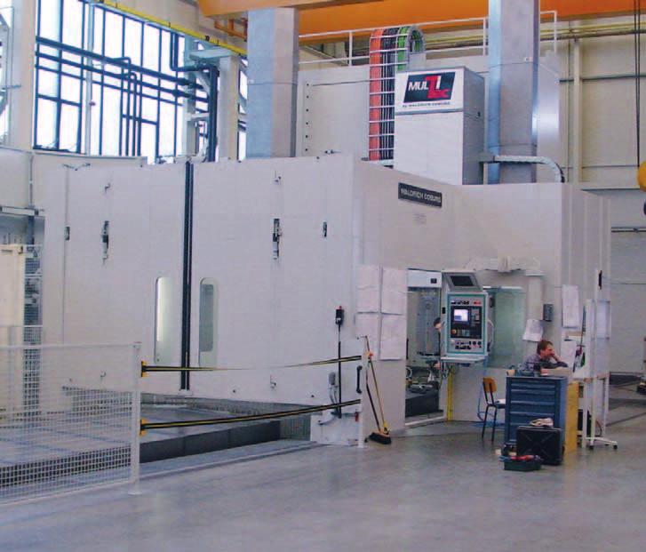
8 Conveyor systems. Reliability and experience based on tradition. Our scraper belt, hinged belt and belt conveyors embody more than 30 years of experience. Systematic further development of our products and adaptation of their func- tions for use with the latest generation of machines guarantees you the utmost level of reliability. Every production machine requires a disposal system In the metalworking industry, tonnes of metal chips are created every day at cutting machine tools. We offer the right chip removal system and the suitable conveyor for your specific application. For disposal of chips at machine tools For transporting metal scrap and chips away from saws For disposal at stamping presses and laser cutting systems For disposal of edge scrap at trimming shears in coil cutting systems For transporting away casting waste in foundry lines Standard hinged belt conveyor at a CNC boring machine From standard to customized we have a solution Everything from a single source planning, design and manufacturing Standard conveyors available within a short time For an individual solution we will work together with you to design a suitable conveyor The optimal solution for whatever material is to be conveyed: hinged belt conveyor, scraper conveyor or belt conveyor Can be supplied with coolant processing if required Quality and long service life are our strong points Spare parts supplies are of course ensured for years to come Great price-performance ratio Hinged belt conveyor developed for the Trumpf TUBEMATIC laser cutting machine. Special hinged belt plates prevent jamming of the material to be conveyed. 8 Subject to change.


9 Designs and areas of application Conveyors are an aspect of mechanical engineering, and are used especially on cutting machine tools. For many applications it is possible to use our standard models. The material to be conveyed, volume to be conveyed, and space limitations often already determine the type of conveyor. In most cases, the variable dimensions such as the belt width, feed length, discharge height and incline are sufficient to take the requirements of the specific application in to account. Hinged belt conveyors Scraper belt conveyors Belt conveyors We also plan and manufacture special conveyors for very specific requirements, even complete chip disposal systems with machine cleaning, crushing, workshop cleaning and hopper storage. Hinged belt conveyor for loading of a hopper system Special model at a trimming shear with a belt width of 900 mm Scraper conveyor for distribution of various chip materials Scraper conveyor under a hopper system for aluminium chips Subject to change. 9

10 Hinged belt conveyors. Proven for a wide range of disposal tasks. Transportation of the material takes place on the upper trough of a revolving hinged belt. Drivers ensure transport of the material up the inclined section. For wet machining the cooling lubrications are collected in the conveyor housing and can be fed back into the machine circuit via an optionally available coolant container or a pump station. Our hinged belt conveyors can be used either as stand-alone conveyors at machine tools, or as linked conveyor systems. Depending on the design, the material to be conveyed is brought to the required height at a defined incline and then discharged. This way we can solve your disposal tasks in over 80% of all cases: Wet or dry chips Workpieces and waste Hot forgings Stampings and punching scrap And much more Hinged belt conveyors Structure Stable metal plate construction Standardized housing cross-section with variable width Robust worm gear motor with torque switching Customized discharge height Customized incline standards = 30, 45 and 60 Floor mounting or as a push-in version into the machine base Accessory examples Motor monitoring systems with currentmonitoring relay Other overload safety devices (on request) Coolant container with pump station Direct electrical connection to your machine controller Other special solutions are available. Please do get in touch with us, we will be happy to advise you. 10 Subject to change.
11 Typical designs Straight design Straight/rising design Can be used in a horizontal or inclined position. Max incline 45 Max. incline 45 Straight/rising/straight design Max. incline 60 Subject to change. 11


12 Hinged belt conveyors. Proven for a wide range of disposal tasks. Types and main areas of application SRF the elegant small one, and particularly compact. Pitch of the hinged belt t = 40 mm With its small pitch (40 mm) and extremely compact design, this conveyor is suitable for even the smallest machine tools. SRF the classic, and our best seller. Pitch of the hinged belt t = 63 mm The conveyor type for most mechanical engineering applications. SRF the big one and especially robust. Pitch of the hinged belt t = 100 mm With a pitch of 100 mm, this conveyor is particularly useful when large quantities of chips are present. SRF the strongest one we build. Pitch of the hinged belt t = 150 mm Special solutions with 150 mm pitch for transporting away of large outputs or large parts. 12 Subject to change.


13 Hinged belt designs Various hinged belt designs are available for different operating conditions: Hinged belt (standard) for dry materials and chips with a low proportion ofcoolant Hinged belt with perforations for pre-separation of coolant for materials with a high proportion of coolant Hinged belt conveyor with corrugations for transporting sticky parts Standard dimensions t H K B SCH B K Type Pitch Box height Hinged belt width Box width t H K B SCH B K SRF , 200, 250, 300, 450, 600 B SCH + 75 mm SRF , 300, 450, 600, 750, 900 B SCH mm SRF , 300, 450, 600, 750, 900 B SCH mm SRF , 450, 600, 750, 900, 900 B SCH mm Special widths on request. Subject to change. 13
14 Hinged belt conveyors. Proven for a wide range of disposal tasks. Dimensions of conveyor housing HB HK 60 B K B AG HB L U L AG L AW L A AAV 30 HK L G Possible incline 0 B SCH B K L U HK HK HKE HB Variable dimensions: B Sch = Hinged belt width B K = Box width B AG = Feed width H B = Panel height AA V L AG L AW L G α = Distance between axles, vertical = Feed length = Discharge length = Total length of the conveyor = Incline Design-dependent dimensions: H K = Box height H KE = Retracted box height L A = Length of the tail (discharge) L U = Length of the tail (feed) The tensioning station is located at the discharge. Dimensions in mm Type H B H K H KE L AW L A L U min SRF SRF SRF SRF The enquiry form can be found on page Subject to change.
, thus forming a hinged belt assembly. Dimensions in mm t Type t S SCH H S SRF 040.00 40 1.5 20 SRF 063.00 63 3.0 35 SRF 100.00 100 3.5 60 SRF 150.00 150 5.")

15 Dimensions of hinged belt Manufactured of strip steel, the hinged belt plates have roller-formed hinge eyes, and are connected by means of axles to the side chains (which are designed as hollow pin chains), thus forming a hinged belt assembly. Dimensions in mm t Type t S SCH H S SRF SRF SRF SRF B SCH Definitions: t = Pitch B Sch = Hinged belt width S SCH = Plate thickness of the conveyor H S = Height of the side rim H S S SCH Dimensions as a function of the hinged belt width Dimensions in mm Type B SCH B K B AG SRF SRF SRF SRF B K B AG B SCH HB Definitions: B SCH = Hinged belt width B K = Box width B AG = Feed width HK Subject to change. 15

16 Scraper conveyors. For disposal of small materials. Transport of the material takes place via drivers which push the material along the floor of the housing towards the discharge. Cooling lubricants are collected in the conveyor housing and can be fed back into the machine circuit via an added-on container or a pumping unit. Our scraper conveyors can be used as standalone conveyors at machine tools or as linked conveyor systems. Depending on the design, the material to be conveyed is brought to the required height at a defined incline and then discharged. The solution for small and short chips: Frequently used for machining of non-ferrous metals Can also be used for very hard, short chips Casting chips, milling chips and sawing chips Scraper belt conveyors Structure Stable metal plate construction Standardized housing cross-section with variable width Robust worm gear motor with torque switching Customized discharge height Customized incline standards = 30, 45 and 60 Floor mounting or as a push-in version into the machine base Accessory examples Motor monitoring systems with current monitoring relay Other overload safety devices (on request) Coolant container with pump station Direct electrical connection to your machine controller Other special solutions are available. Please do get in touch with us, we will be happy to advise you. 16 Subject to change.

17 Typical designs Straight design Straight/rising design Can be used in a horizontal or inclined position. Max incline 45 Max. incline 45 Straight/rising/straight design Max. incline 60 Subject to change. 17


18 Scraper conveyors. For disposal of small materials. Types and main areas of application KRF 040 the classic scraper conveyor Pitch of the scraper belt t = 40 mm Our standard scraper conveyor for smaller machine tools and small quantities of chips. KRF 063 for somewhat bigger tasks Pitch of the scraper belt t = 63 mm For larger machines and larger quantities of chips. KRF 100 the strongest one we build. Pitch of the scraper belt t = 100 mm Special solution for very large quantities of chips 18 Subject to change.


19 Standard dimensions t H K B KR B K Type Pitch Box height Scraper belt width Box width t H K B KR B K KRF , 200, 250, 300, 450, 600 B KR + 90 mm KRF , 300, 450, 600, 750, 900 B KR mm KRF , 300, 450, 600, 750, 900 B KR mm Special dimensions on request. Dimensions of conveyor housing L U L AG L AW L A HK AAV B K B AG HK 0 L G Possible incline B KR Dimensions in mm B K L U Type H K H KE L AW L A L U min HK HK HKE KRF KRF KRF Variable dimensions: B KR = Scraper width B K = Box width B AG = Feed width The enquiry form can be found on page 72. AA V L AG L AW L G α = Distance between axles, vertical = Feed length = Discharge length = Total length of the conveyor = Incline Design-dependent dimensions: H K = Box height H KE = Retracted box height L A = Length of the tail (discharge, incl. tensioning distance) L U = Length of the tail (feed) Subject to change. 19

20 Belt conveyors. The all-rounders also for parts with sharp edges. Our belt conveyors are predominantly used on punch-nibbling machines, for transporting punching scrap and punching trimmings. However, other parts can also be transported, such as waste parts from plastic injection machines. The transport belt of the conveyor is resistant to oil and grease. Belt conveyors Structure Housing made of steel plate Oil-resistant belt Protective motor switch Convex return shafts Shafts with ball bearings The universal transport solution, for applications where no cooling lubricant is present. Also suitable for parts with sharp edges Not suitable for transporting hot chips Adjustable belt tension 20 Subject to change.


21 Standard design Standard design Can be used in a horizontal or inclined position. Max incline 30 Standard dimensions F L H K B G B K Type Box height Belt width Box width Maximum conveying length H K B G B K F L BK Dimensions in mm GBF , 200, 250, 300, 450, 600 B G Special widths on request. The enquiry form can be found on page 74. Subject to change. 21

22 22 Photograph: Waldrich Siegen Werkzeugmaschinen GmbH

23 Guideway protection systems. Perfect protection for guideways on machine tools. Page Telescopic covers Way wipers Link apron covers Bellows Conical spring covers Conveyor belt covers


24 Telescopic covers. Perfect protection for guideways on machine tools. Wherever guideways on machines have to be protected, we have a suitable solution. Our guideway protections systems boast a high degree of operational reliability, a long service life, and make use of innovative technical solutions. Every production machine requires protection for its guideway Today, modern machine tools process workpieces at ever-greater cutting and travel speeds. The protection of guideways, measuring systems, drive elements and other vulnerable parts is absolutely essential. Accelerations and speeds of machines are constantly increasing. Telescopic covers must also be able to cope with these challenges. This is where telescopic covers with harness mechanisms are used. Cross-beam cover at a milling machine From individual manufacture to series production we have a solution The number of varieties is immense, no cover for a machine is exactly the same as any other. Series cover Special form of an inclined bed cover on a test framework 24 Subject to change.

25 Designs and areas of application Until the 1970s, telescopic covers seldom moved in speed ranges any greater than 15 m/min. The expansion and compression of the individual boxes took place sequentially. Due to the low speed, there was hardly any impact noise. Over the years, however, Improvements in drive technology have increased the travel speeds of the machines and thus also the speeds of the cover. At high travel speeds, the impact pulse exerted on the cover becomes truly enormous. This results in loud impact noises. What is more, the telescopic cover is subjected to very large mechanical stresses. The landscape for telescopic covers has changed greatly in the last few years. Old designs are less and less in demand, with modern concepts such as covers with differential drives taking their place. Telescopic cover with flat shape on a boring machine Telescopic covers are generally produced from cold-rolled uncoated thin plates in thicknesses from 1 to 3 mm. In case of extremely aggressive environmental conditions (e.g. aggressive cooling lubricants), corrosion-resistant stainless steel plates may also be used. The new generation of KABELSCHLEPP telescopic covers also allows the use of semifinished products with surface finishings such as: Plates with pure zinc coatings Plates with zinc/nickel coatings Plates with lead/zinc coatings This ensures substantial protection against corrosion. Subject to change. 25
26 Telescopic covers. The speed is decisive. At speeds below 15 m/min a telescopic cover can still be built in the conventional form of box synchronization. At higher speeds, however, the inevitable impact noises become clearly audible and unpleasant. So-called differential drives serve to synchronize the boxes and eliminate the impact noises. KABELSCHLEPP has chosen the old, proven harness mechanism principle, in which special materials are used. Telescopic cover with damping elements Wiper systems in various designs Rollers / sliders Gully in various designs Damping systems in various designs Structural metal plates to prevent slipping (on the largest box) Lifting element Locking system 26 Subject to change.
27 Travel speed Up to 15 m/min Up to 30 m/min Up to 60 m/min Damper elements / harnesses Not required Damper elements Damper elements / harnesses The use of damping elements depends on the travel speed and the moving mass. The information in the table should therefore only be viewed as guide values. Telescopic cover with harness mechanism Wiper systems in various designs Rollers / sliders Lifting element 4 5 Locking system Synchronising device (harnesses) for fast-running telescopic covers Subject to change. 27


28 Mechanical elements with harnesses. KABELSCHLEPP sets the mark. To ensure impact-free expansion / compression of telescopic covers, they are used with so-called synchronisers (harnesses). As a result, all of the cover boxes move evenly during expansion and compression. The individual boxes move relative to each other only at a differential speed. Telescopic cover with proven harness mechanism in various expansion states. SXM Synchronized Expansion Mechanism. The KABELSCHLEPP harness technology is used wherever you find this symbol. Telescopic covers with harness mechanisms have many advantages: High travel speeds up to 200 m/min are possible. Acceleration forces and speeds are uniformly distributed across all the plates. This also applies to the resultant inertial forces. The force peaks that would normally occur when the telescopic covers dashed against each other do not occur. The disruptive impact noise of the boxes is eliminated. 28 Subject to change.


29 Cover with two harnesses This solution has been developed for travel speeds greater than 100 m/min. Two harnesses ensure synchronization. In the example shown here the cover plates are made of 1 mm thick stainless steel. The cover plates are riveted to the rear wall. Welding and the resulting heat effects have been avoided. Only the wiper is spotwelded. Telescopic cover with proven harness mechanism Cover with one harness This particularly lightweight solution has been developed for small machine tools. The cover plates are made of 1 mm thick normal steel. The travel speed in this special application is only 30 m/min. The harness mechanism serves to ensure synchronization, however, and the reduced mass of all the elements means that it was possible to develop an especially cost-effective solution here. Telescopic cover with only one harness Subject to change. 29


30 Telescopic covers. Perfect protection for guideways on machine tools. Photograph: Waldrich Siegen Werkzeugmaschinen GmbH Designs Machine tools come in a wide variety of designs. That is why a modern lathe needs another type of telescopic cover than, for example, a large bed-type milling machine. The following designs provide an overview of typical designs. Flat shape Roof shape, centric (eccentric) The U-shaped design is generally used in a horizontal, lying position for milling table guides. With this design the maximum width of the telescopic cover should be limited to 1.5 m. This design is always advisable when cooling lubricants are used. The inclined surface allows the water and naturally also the chips to run off more easily. With large covers (> 3 m width) for reasons of stability, etc. at least three roof angles should be provided. 30 Subject to change.


31 Flattened roof shape The flattened roof shape is a special construction method with two roof angles. Primarily for dry operation and widths > 3 m. Shape with incline to one side The shape with incline to one side has a special roof shape. Depending on the possible incline, covers can be constructed with widths of up to 1.5 m. This shape is likewise a recommended solution when large amounts of coolant are present. Depending on the angle of incline, this form also helps to discharge coolants / chips. Vertically-installed telescopic cover Standing covers are used on larger machine tools, mostly in the area above and below the cross beam. They can take many different shapes. Blind cover With blind telescopic covers, the cover plates move in separate guide rails, each of which is mounted on the machine at the sides. It is used exclusively in a vertical arrangement. The guide rails are generally made of brass. Cross-beam cover These covers are predominantly used on large gantry machine tools on a cross beam to the left and right of the support. The boxes are suspended vertically and protect the support guides from chips and cooling lubricants. Tubular cover, polygonal cover Tubular covers or covering shafts, spindles, etc. They can be made either with a round or a polygonal shape. The enquiry form and the design dimensions can be found on page 75ff. Other forms and special designs tailored to your specific requirements are possible. Please do get in touch with us, we will be happy to advise you! Subject to change. 31


32 Wipers on telescopic covers. Wipers on telescopic covers keep the cover boxes clean and prevent the penetration of dirt and chips. Welded-on and riveted-on wipers With these types the support profile is spotwelded or riveted to the cover box. Type MA 8 / MA 12 These wipers consist of an NBR profile vulcanized onto a steel strip. Necessary calculated distance of the cover plates 2.5 to 3.5 mm. 1.5 Supporting strip optional Supporting strip optional Wiper type MA 8 Wiper type MA 12 Type MA 8S / MA 12S Wipers MA 8 and MA 12 are covered with a protective strip for protection against hot chips. Necessary calculated distance of the cover plates 3.5 to 4 mm. 0.5 Protective strip Wiper type MA -S Type MA 12.1 / MA 18 A specially-milled steel plate profile is spot-welded to the boxes and a PUR wiper lip is inserted. Necessary calculated distance of the cover plates 3.5 to 5.5 mm Wiper type MA 12.1 Wiper type MA Subject to change.


33 Welded-on and riveted-on wipers Steel plate wiper made of spring band steel A specially shaped, approximately 0.4 mm thick, approximately 25 mm wide band of stainless spring band steel is spot-welded to the cover plate. This wiper is recommended for dry machining. Necessary calculated distance of the cover plates 1 mm. Types with replaceable wiper lips the new generation The replaceable wiper with a PU lip This new generation of wipers can be replaced directly on the machine, without disassembling the telescopic cover. The wiper consists of four parts: a retaining section of steel, a wiper lip of PU, a spring profile of plastic and a fastening pin. By rotating the fastening pin through 90, the wiper system is fastened to the cover plate, or loosened from it. The spring profile generates a defined pressure. Necessary calculated distance of the cover plates 5 to 5.5 mm. The replaceable wiper made of steel Here a solution has been developed that makes the above-mentioned spring band steel wipers replaceable. A specially-shaped support plate is spot-welded to the box. The wiper can then be pushed in. The spring force of the support plate holds the wiper in place. The holding forces are increased by defined fixing points. Necessary calculated distance of the cover plates 1 mm. Subject to change. 33


34 Damping elements on telescopic covers. Telescopic covers with travel speeds greater than 15 m/min must be provided with dampers in order to reduce impact noises. Wiper type MA 18 with damping The support profile is made of aluminium and is screwed or riveted on. The wiper lip is identical to MA The special damping profile can be installed in the rear aperture formed onto the support profile. Necessary calculated distance of the cover plates 5.5 mm. Brass strips with damping Brass strips are used primarily on standing covers. The damping profile described above can likewise be mounted on an appropriately drawn brass profile. Necessary calculated distance of the cover plates 5.5 mm. Vibration absorber To damp impact noise effectively, vibration absorbers can be fitted in the rear walls of the covers. Depending on the individual situation and travel speed, the number of dampers is varied in order to achieve an optimum result. Damping elements for compression Damping elements that only work during expansion require an additional element for compression. Here simple rubber buffers mounted at an appropriate point on the rear wall have proven themselves over many years. 34 Subject to change.


35 Splash- and hose-proof protection on telescopic covers. Over time cooling emulsion and fine chips can be pumped under the individual boxes and make it over the rear wall into the machinery space that is being protected. In many cases this is undesirable. Machine tools with hydrostatic bearings require watertight covers. Gullies for telescopic covers In order to catch coolant and chips that make it over the rear wall, a gully is generally installed on the back of the rear wall. This gully allows the fluids to be drained off to the sides. Aluminium gully type AL 19 This gully is an extruded aluminium profile which is screwed onto the rear walls of the cover. The cover plate is bent downwards so that it projects into the gully. This allows the coolant between the plates to flow into the moulded gully. Condensation water that forms under the cover plates is wiped off by a lip and drained into gullies to the front and back. This makes it possible to achieve a very high level of waterproofing. Gully type ST 05 This gully is screwed onto the rear wall. This has the advantage of, among other things, meaning that galvanized metal plates can be used (no welding necessary). The enquiry form can be found on page 75. Subject to change. 35


36 Rollers and sliders on telescopic covers. The individual boxes of telescopic covers are supported by rollers or sliders on the guideways or corresponding supplementary guides. In addition, there are various solutions depending on the qualities of the way: Plastic rollers Gentle rolling on the guideway For low travel speeds Steel rollers For high support loads For high travel speeds Plastic sliders Good sliding characteristics on the guideway For high travel speeds Can also be used for linear guides Metal sliders For high support loads For low travel speeds 36 Subject to change.

37 Telescopic covers the new generation. New developments from KABELSCHLEPP. DUPLEX, the vertically traversing cover These covers are used to separate two machining cells of a machining center. Thus, a tool change can be carried out in one machining cell, while work continues in the other one. The partitioning of these two machining cells has to be nearly bulletproof, because there are several persons working in one of them, who would be in grave danger without protection. The vertically traversing telescopic cover DUPLEX is guided by two inside harness mechanisms. Owing to the double-construction, a high degree of puncture-proofness is achieved, which more than satisfies the requirements. Of course, this construction principle can also be employed for normal covering tasks. Since the covering elements are simply suspended on the harness, very inexpensive solutions are obtained. DUPLEX cover Subject to change. 37

38 Telescopic covers the new generation. New developments from KABELSCHLEPP. CROSS-COVER, the ready-to-install solution Today machining spindles of horizontal drilling machines move in the vertical and horizontal direction with accelerations in the 2 g range and high speeds. Cover elements for the transverse motion are always in a vertically standing arrangement and move laterally, cover elements for the vertical motion of the spindle move upwards and downwards, and all of their lamellas are arranged horizontally. Today the machinery space is often protected with bellows, whose fabric structure is often protected against flying chips by means of supplementary lamellas made of stainless steel. Due to the greater lengths of the plates, the side covers are made, for example, of 1 mm steel, and the wiper is generally mounted separately. The construction with harnesses is superior to normal covers and other protective systems such as bellows with regard to durability and stability. This pays for itself in the long run, since there is virtually no wear (tested so far: 300,000 motion cycles). At the same time, the weight has been kept low, and ball bearing guide rails ensure smooth, low-friction operation. KABELSCHLEPP has developed the turnkey system CROSS-COVER. The entire machinery space covering is supplied as a pre-finished unit. The CROSS-COVER is constructed of slim, light plates, which move evenly thanks to integrated harness mechanisms. This eliminates disruptive impact noise, minimises wear and increases service life significantly. The vertically moving plates are preferably made of very hard stainless spring band steel with an integrated wiper. With CROSS-COVER you save valuable time We ship the entire cover unit to you ready for mounting you can completely cover the spindle side with just a few installation steps. Installation is aided by a frame running around the machine. We design this frame according to your specifications, and ship it to you together with all of the necessary fastening elements. Ready-to-install CROSS-COVER cover 38 Subject to change.


39 IN-LINE-COVER, the alternative to bellows and link apron covers Wherever up until now bellows or link apron cover solutions have been used to prevent entry of chips, now there is a slim, robust, cost-effective alternative. This design saves weight, and at the same time increases stability and allows narrow lamellas. It also reduces weight significantly compared to a telescopic cover. KABELSCHLEPP IN-LINE-COVERS offer the resistance capacity of telescopic covers with less weight and lower costs. For example, you can use IN-LINE-COVERS as a cross-beam cover on gantry machine tools to protect their vulnerable drive systems against particles and fluids. Or as an alternative to link apron covers when machine components have to move in one dimension. With the IN-LINE-COVER, the harness mechanisms provide more even motion and very smooth operation. Here, too, the KABELSCHLEPP SXM harness principle prevents force peaks and excessive noise generation. A construction method which has proven itself thousands of times over. New, on the other hand, is the suspension of the plates at the central pivot point of two harnesses and guidance of the harness points on one or two guide rails. IN-LINE-COVER with harness mechanism The individual plates of the cover are made of mm thick spring band steel, normal steel or stainless steel, depending on the length of the specific element: very light (reduced weight) Corrosion-resistant when stainless steel is used Long service life Subject to change. 39


40 Way wipers. The cleanup crew on guideways. Way wipers are essential to keep the guideways in a proper functional state, and thus to keep the machine tool permanently in operation. Even if the guideways are already protected by a telescopic cover, it is necessary to wipe fine, penetrating particles off of the vulnerable ways. Harnessed way wipers Cast wiper with steel support strip Way wipers in a modular system BAY-WIPE way wiper with optimised corner design. 40 Subject to change.


41 Overview and delivery forms Harnessed way wipers proven in millions of applications Available in a wide variety of shapes, harnessed according to your specifications, in bar form or available ex-stock. Way wiper BA 65 Cast wiper with steel support strip, available ex-stock in bar form. Way wiper BA 115 with extra-long lip Highly-flexible cast wiper with steel support strip, available ex-stock in bar form. Way wipers in a modular system the clever solution The most economical alternative to cast wipers. Subject to change. 41


42 Way wiper types BA and BAS. Wipers of this type have a replaceable lip and guarantee high form stability and mechanical loading capacity. They are manufactured in custom forms according to your specifications. Available as bar material ex-stock. Note: Reduce costs With types BA and BAS the wiper lip is replaceable. In case of wear, only the lip has to be exchanged; the support profile can remain in use. Properties Temperature range -40 C to 100 C Support material: Aluminium Wiper lip material: Polyurethane Largely resistant to oils, greases, alkalis and water Pretension approx. 2 mm Replaceable wiper lip Standard length of bar material: 1000 mm Inside or outside wiping forms are possible 42 Subject to change.
 BA 18 17.5 BA 25 23.")
 BAS 18 17.5 BAS 25 23.5 BAS 40 39.")
43 Dimensions and types Type BA Way wipers of this type are used mainly in those cases where installation conditions are restrictive, or where the wipers are additionally protected by means of a telescopic cover, a bellows, a link apron cover, or where no chips occur. Type Installation height H (clamped in position) BA BA Standard length: 1000 mm Type BAS In this type series, the light metal support provides protection for the wiper lip. It is used primarily in the case of direct incidence of chips (no hot chips). Type Installation height H (clamped in position) BAS BAS BAS Pre-wiper for protection of the guideway To protect the wiper lip from hot chips, and to remove coarse and stubborn dirt from the guideway, the way wiper must be fitted with a pre-wiper made from stainless spring steel or brass. The pre-wiper and its corresponding light metal clamping strip are affixed to the machine component with the fastening screws of the wiper. For straight way wipers with a corresponding hole pattern (distance between holes 80 mm), the clamping strip is not required. Standard length: 1000 mm The enquiry form can be found on page 79. Subject to change. 43

44 Way wiper BA 65 bar material. Wipers of this type are compact and are notable for high shape accuracy and dimensional accuracy. It is manufactured in various forms, thus guaranteeing high repeatability. Properties Temperature resistance 40 C to C, briefly up to 140 C Support material: Steel Wiper lip material: Abrasion-resistant synthetic rubber (NBR) Resistant to standard oils, greases, acids and bases Resistant to microorganisms Dimensions Way wiper BA Way wiper BA Way wiper BA Way wiper BA Type BA BA BA BA Pretension (max.) 1 mm 1 mm 2 mm 1 mm Length: 500 mm The enquiry form can be found on page Subject to change.
45 Way wiper BA 115 bar material. Highly flexible wiper with a max. pretension of 4 mm. It is likewise manufactured in various forms, guaranteeing high repeatability. Properties Temperature resistance 40 C to C, briefly up to 140 C Support material: Steel Wiper lip material: Abrasion-resistant synthetic rubber (NBR) Resistant to standard oils, greases, acids and bases Resistant to microorganisms Dimensions Way wiper BA Type BA Pretension (max.) 4 mm Length: 500 mm The enquiry form can be found on page 79. Subject to change. 45
46 Way wiper BA 65 VARIO The most economical alternative to cast wipers even for small quantities. On request we also manufacture them according to your specifications custom tailored for your application. BA 65 VARIO way wipers are optionally available as complete wipers, or as individual wiper lips in bar form for your own harnessing. So-called cast wipers are wipers consisting of a piece of neoprene rubber vulcanised onto a steel support profile. They are produced in specially-manufactured injection moulds. Larger quantities are essential, as the tool costs must be offset by the number of parts produced. The wiper system BA 65 VARIO is a new development for which no special tools are required: A pre-finished profile of synthetic rubber is custom-tailored. The support profile usually made from metal can be produced on a laser or nibbling machine. Thus smaller quantities can be produced in this way at a reasonable cost. Properties Temperature resistance 40 C to C, briefly up to 140 C Support material: Steel, stainless steel Wiper lip material: Abrasion-resistant synthetic rubber (NBR) Resistant to standard oils, greases, acids and bases Pretension of the wiper lip: max. 1 mm Resistant to microorganisms The enquiry form can be found on page Subject to change.
 1 mm BA 65-18 1 mm BA 65-25 1 mm Length: 500 mm 6.5 Way wiper BA 65-25 VARIO Delivery options 1.")


47 Dimensions Way wiper BA VARIO Way wiper BA VARIO Type BA Pretension (max.) 1 mm BA mm BA mm Length: 500 mm 6.5 Way wiper BA VARIO Delivery options 1. Construction set as individual parts The support material and wiper lips are produced according to your specifications, and put together as a construction set. 3. Separate wiper lip If your production department can produce the required support plates itself, you can order the wiper lip from us separately. The delivery length is500 mm. It can be ordered as follows:...pcs. wiper lip BA material no pcs. wiper lip BA material no pcs. wiper lip BA material no Easy assembly of the individual parts 2. Ready-to-install wiper system All parts are supplied affixed to the support profile. Wiper lip bar material Ready-to-install wiper system Subject to change. 47


48 Way wiper BAY-WIPE. System with optimised corner design. Many wiper systems have problems at the point where a hydrostatic guideway goes round a corner. Rounded or bevelled corners on guideways are often problem areas, because the wiper elements cannot follow the profile closely enough. Our BAY-WIPE system now has these problem areas perfectly under control. Thanks to its optimised corner elements, which follow the contours of the path exactly, the guideway is wiped clean in both directions. Properties Effectively prevents lubricants and coolants from escaping Corner elements to ensure perfect contact Modularly configured wiper system Max. 0.3 mm deformation of wiper edge Grease- and acid-resistant wiper lip Standard length of bar material: 500 mm Intelligently designed, individually produced The wiper lip of the BAY-WIPE was developed at the Institute for Machine Elements (IMA) at the University of Stuttgart. elements. This allows a wiper system to be created from the individual parts, exactly suited to the contours of the guideway. KABELSCHLEPP participated in this research project, and put the results into practice in a consistent manner. A wiper lip that works in both directions is affixed directly to the support profile by means of a plastic injection moulding process. The straight sections of this profile, which have been cut to length, are then nonpositively joined with pre-assembled corner The enquiry form can be found on page Subject to change.

49 Link apron covers. Solutions for limited spaces. Link apron covers can be used anywhere where, for reasons of space, it is not possible to use telescopic covers. They lie directly on the guideways and can hang down freely at the end of the path, or be screwed on or wound around without any special guides. Properties Small space requirement Protection against chips and lubricant Splash- and hose-proof Low weight Long service life Hear-resistant to 100 C over extended periods Customized end attachment All link apron covers can be supplied with a roller device Lateral guides are not necessary Short delivery time Attractive price/performance ratio Subject to change. 49

50 Link apron covers. Solutions for limited spaces. Designs Design 1 Lightweight, highly flexible solid profile link apron covers, thin design. Bmin = 100 mm B max = 950 mm R min = 25 mm Weight = 5.6 kg/m 2 Solid aluminium profile 19 x 3.0 mm with PU connecting elements Design 2 Robust solid profile link apron covers, for high stress. B min = 100 mm B max = 2950 mm R min = 50 mm Weight = 14.2 kg/m 2 Solid aluminium profile 20 x 5.5 mm with PU connecting elements Design 2N Lightweight, stable hollow profile link apron covers, extremely stress-resistant, even in large widths. B min = 100 mm B max = 2950 mm R min = 50 mm Weight = 10 kg/m 2 Hollow aluminium profile 20 x 5.5 mm with PU connecting elements Design 3 Flexible solid metal link apron cover, with hinges and one-sided bend radius. B min = 100 mm B max = 2000 mm R min = 60 mm Weight = 16.5 kg/m 2 Hollow aluminium profile 18.5 x 6.8 mm with integrated hinge 50 Subject to change.


51 Fastenings / connecting elements Examples of fastening profiles Standard end profile Standard profile with mounting bracket Straight end profile Angle fastening profile Installation variants Roller devices All link apron covers can be rolled up like a window blind. They can be driven with spring or electric motors. The enquiry form can be found on page 80. Subject to change. 51


52 Steel link apron covers FLEX-COVER. Lighter, tougher, more economical. The new FLEX-COVER link apron cover represents a small revolution: it is made from sheet steel, making it 3 times more robust than aluminium but weighing the same. Its completely new construction means that penetration by fluids and chips is virtually impossible. The individual elements roll against each other in the radius of the lamellas. There is hardly any wear, as there is no friction, and no bendable connection elements that could be exposed to fatigue. FLEX-COVER gives you improved properties with no increase in weight, and at a considerably lower price. The specially-milled sheet steel lamellas are held together by a slotted plastic tube, which is itself affixed by means of spring steel clips. Properties 52 Rustproof steel lamellas 3 times greater resistance to flying chips Each lamella has a completely smooth surface Hardly any wear of steel or plastic parts Virtually no penetration by chips or fluids Bmin = 200 mm Bmax = 2000 mm Lmax = 2500 mm Rmin = 50 mm Weight = 10 kg/m 2 Heat resistance: approx. 80 C Travel speed: 1.5 m/s Acceleration: up to 15 m/s 2, depending on the specific application Subject to change.

53 Bellows. Guideway protection solutions with very little compression. KABELSCHLEPP bellows are used on all kinds of machine to provide protection for guideways and spindles, in those cases where no hot chips are present and accessibility is not a requirement. Bellows can be individually produced from a range of different materials, depending on your specific requirements. Properties Simple installation High travel speed Minimal compression Installation variants Horizontal, lying Horizontal, hanging Vertical High quality Delivery options For travel speeds of up to 1.5 m/s Customized production Available in a wide range of shapes Available in many different materials Subject to change. 53

54 Bellows. Guideway protection solutions with very little compression. Designs U-bellows design Variable dimensions Customized in the guide Economically priced U-bellows design Box bellows design Covering for movable machine elements High form stability Box bellows design U-bellows design with lamellas Reliable protection against heavy chip generation Rust-resistant and acid-resistant telescopic plates Can be made coolant-proof upon request Rigid or movable design of the telescopic plates is possible U-bellows design with lamellas Additional shapes and designs are available on request. The enquiry form can be found on page Subject to change.

55 Conical spring covers. Protection under extreme conditions. Conical spring covers protect spindles, columns, shafts, threads and rod guides reliably against contamination, chips and mechanical damage. They provide a good sealing function, and are self-cleaning if installed in a suitable position. High temperature resistance and resistance to chemicals guarantee reliable protection even under extreme operating conditions. The springs are made of hardened high-quality spring band steel. The optimized design means that the horizontal bending and vertical deflection is very low. Thus even in the extended state KABELSCHLEPP conical spring covers guarantee excellent protection against dirt and mechanical influences. Properties Accident prevention for operating personnel from revolving spindles and shafts Reduction in downtimes resulting from contamination Increased machine service life Some conical spring covers are also available for retrofitting Subject to change. 55


56 Conical spring covers. Protection under extreme conditions. Installation positions The conically wound conical spring covers automatically follow the motions of the machine. Made of high-quality blue polished steel or alternatively of stainless steel, they can be used in vertical, horizontal and inclined positions. Vertical installation When installed vertically, conical spring covers are mounted with the larger diameter at the top. This way the overlapping of the individual coils makes the conical spring covers self-cleaning. Horizontal installation When installed horizontally, conical spring covers are mounted with the larger diameter in the direction of the chip generation. In horizontal installation with larger diameters or longer expansion, the maximum expansion is reduced to 60% of the value for vertical installation. Moreover, a slight sag appears in the conical spring cover, which is about 2-5% of the maximum expansion. Installation in inclined position In addition to vertical and horizontal installation, installation in an inclined position is also possible. For small angles of incline above the horizontal the same conditions apply as in horizontal installation. 56 Subject to change.

57 Installation of several conical spring covers in series By connecting several conical spring covers in series it is possible to deal with special requirements, such as extra-long traversing distances. We would be happy to advise you regarding such applications and can supply you with the necessary special flanges. Retrofitting Outside flange Many conical spring covers are also available for retrofitting. Conical spring cover Selection Selection of the conical spring cover suitable for your specific application is generally based on the following criteria: Internal diameter D1 Expansion AZ (vertical / horizontal) Compression ZD Inside flange The enquiry form can be found on page 82. Subject to change. 57

58 Roll-up covers. Protection in a minimum of space. KABELSCHLEPP roll-up covers serve to protect contact surfaces and guideways on all kinds of machine. Properties For high travel speeds Minimal space required Customized production Simple installation Long service life Cost-effective Designs Roll-up cover without housing Roll-up covers without a housing are suitable for areas with limited space, and facilitate optimal integration into the machine enclosure. Roll-up cover with housing Roll-up covers with an additional housing made of steel or aluminium protect the standard roll-up cover and allow simple installation or retrofitting. 58 Subject to change.

59 Roll-up covers with plastic band Reliable protection against cutting waste, oil and cooling emulsions Particularly suitable for high travel speeds thanks to its low own weight Minimal space required Very resistant to tearing due to plastic layered special fabric Various materials are possible Roll-up covers with steel band Very good protection against cutting waste, oil and cooling emulsions Rust-resistant and acid-resistant spring band steel with thickness from 0.2 to 0.4 mm Suitable for high travel speeds and greater mechanical loads Only available with housing The enquiry form can be found on page 83. Subject to change. 59
60 60


61 Machine housings. The impenetrable housing for your machines. Page PROTECT-PANEL


62 PROTECT-PANEL system. The impenetrable housing for your machines. High speeds, quick machining cycles, cooling water and chips: Machine tools represent a dangerous environment for people. This is why all machine tools are contained in nearly impenetrable housings. These help reduce or eliminate the hazards for the persons who work with them. With the KABELSCHLEPP PROTECT-PANEL system, we offer you optimized protection for a particularly attractive price. 62 Subject to change.


63 Steel plate construction for a totally harmonised system Each machine housing is produced individually according to your plans while at the same time consisting of standardised parts. We carry out all of our engineering in 3D, combining various predefined elements to form your housing. Simple, specially developed connecting elements keep the walls in line. The entire system is made of steel. Screwed and riveted connections and a rigorously implemented sandwich construction method are used to turn industrially prefabricated components into extremely stable wall modules, without any need for welding. The wall elements are mounted vertically on solid C-profiles with fastening elements, e.g. on the shop floor. Irregularities in the floor can be compensated for using the adjustment features. This manufacturing method offers you numerous advantages: Short design engineering times through the used of standardised parts wherever possible. Short delivery times, since our production is based on predefined processes. Short installation times, since our mounting profiles are likewise standardised, and the large wall elements can be connected with just a few screws. Processing on state-of-the-art machine tools provides high precision for all elements. Avoiding welding as much as possible eliminates the potential for distortion and irregularities. KABELSCHLEPP PROTECT-PANEL Modules: Wall modules (standard dimensions B x H 1235 x 2350 mm) Window modules (with special glass pane insert) Corner modules Standard doors Sliding doors (manual and automatic) Folding doors (up to three wings are electric motor-driven under PLC control) Lift gates (up to four segments) Roll gates (for vertical and vertical-horizontal motion) Material: Steel plate, 0.5 mm thick, powder coated (colour as desired, RAL 9002 is standard) Subject to change. 63


64 PROTECT-PANEL system. The impenetrable housing for your machines. PROTECT-PANEL: Secure protection against water spray The unique connecting element means that the individual wall elements are sealed against water spray, and are joined to each other in an extra-sturdy manner. Each pair of modules is joined by speciallyformed plates held together by bolts. An additional plate on the inside forms a labyrinth seal. In order to direct the remaining water spray downwards, we have fitted a deflector plate which guides the downward-flowing water directly into a particle conveyor, for example. The special sandwich construction of the wall elements, together with the deflector plate, result in a sealed protective wall which can withstand even high water pressures. Protection against sprayed fluids: Sealed with a rubber seal and deflector plate. An open road for your workpieces with modern drive technology To make exchanging workpieces easier, and if it is not possible to implement a guide rail in the upper and lower areas of the enclosure, then you can equip the enclosure with a folding door which moves to the side. The folding door is suspended only from a lateral post, leaving the greatest possible open space for your workpieces, especially in the upwards direction. The door elements have the same design as the wall elements. Each of them is driven by a 24 V DC motor with a planetary gear unit and integrated PLC controller. Country-specific voltages can easily be obtained using an appropriate transformer. Modern CAN-BUS technology makes it possible to program different motion patterns for individual door elements. Teaching and loading of programs are remarkably simple. If suitable CAN-BUS equipment is present, the motors can also be monitored using the machine controller. When closed, the doors are held together by a locking mechanism, and will not open even if a person leans on them, for example. The end positions can be monitored and interrogated either via the program, or by means of additional limit switches. 64 Subject to change.


65 Gate elements for housings Roll gate for PROTECT-PANEL For changing pallets on machine tools, a gate is required that moves at high speeds when opening and closing. The PROTECT-PANEL roll gate functions in principle like a garage door. A segmented gate moves upwards and is rolled up. The height of the gate structure is 3500 mm. The lamellas of this gate are made from aluminium, and are reinforced on the inside with steel inserts. This guarantees the required penetration resistance. Lift gate for PROTECT-PANEL Unlike the roll gate, the lift gate has a small number of larger segments, which all move together. The segments have a sandwich construction, which makes them extremely resistant to penetration. These larger segments are thus not rolled up, but instead are positioned one behind the other, and hang neatly one behind the other when the door is open. A special feature of this gate is its lifting and lowering mechanism, which makes use of pulleys. Each gate element is suspended on two pulleys, which raise or lower all of the elements evenly. Subject to change. 65


66 PROTECT-PANEL system. The impenetrable housing for your machines. Automatic door for PROTECT-PANEL Because automatic doors are integrated into the machine tool programme, they automatically open and close according to the required production cycle. For heights of 2-3 m that s nothing special. But the automatic door in the PROTECT- PANEL system can manage much bigger sizes. At the production plant of one of our customers, a first automatic door has been installed which is 6500 mm high, 1600 mm wide, 500 kg in weight and can open and close within 5 seconds. It s a challenge that we solved perfectly with the help of linear drives, a three-phase motor and control shaft technology. 66 Subject to change.
67 Subject to change. 67
68 68


69 Enquiry forms. Question forms and technical information. Page Hinged belt conveyors question form Scraper conveyors question form Belt conveyors question form Telescopic covers question form Telescopic covers technical information question form Way wipers question form Link apron covers question form Bellows question form Conical spring covers question form Roll-up covers question form
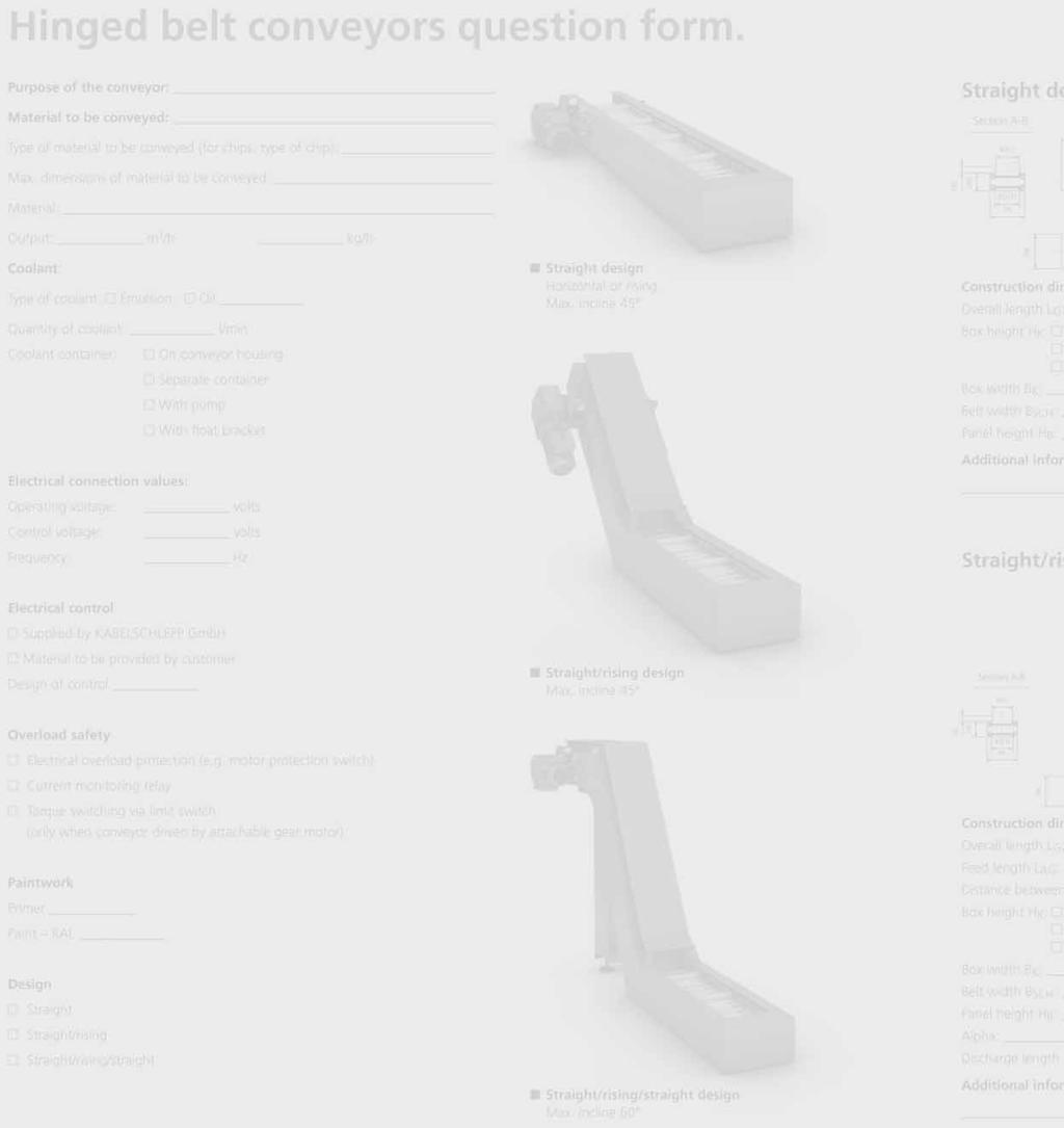
70 Hinged belt conveyors question form. Purpose of the conveyor: Material to be conveyed: Type of material to be conveyed (for chips: type of chip): Max. dimensions of material to be conveyed: Material: Output: m 3 /h kg/h Coolant: Type of coolant: Emulsion Oil Quantity of coolant: l/min Coolant container: On conveyor housing Separate container With pump With float bracket Straight design Horizontal or rising. Max. incline 45 Electrical connection values: Operating voltage: Control voltage: Frequency: volts volts Hz Electrical control Supplied by KABELSCHLEPP GmbH Material to be provided by customer Design of control Straight/rising design Max. incline 45 Overload safety Electrical overload protection (e.g. motor protection switch) Current monitoring relay Torque switching via limit switch (only when conveyor driven by attachable gear motor) Paintwork Primer Paint RAL Design Straight Straight/rising Straight/rising/straight Straight/rising/straight design Max. incline Subject to change.
71 Straight design Straight/rising design Section A-B BAG A LG LG HB HK BSCH BK B Section A-B BAG A LAG LG LAW Section A-B LAG BAG A Alpha B BK AAV Alpha BK Construction dimensions: Overall length L G: mm Box height H K: 140 mm (SRF ) 216 mm (SRF ) 360 mm (SRF ) Box width B K: mm Belt width B SCH: mm Panel height H B : mm Additional information Straight/rising/straight design HB HK BSCH BK BK B Construction dimensions: Overall length L G : mm Feed length L AG : mm Distance between axles, vertical A AV : mm Box height H K: 140 mm (SRF ) 216 mm (SRF ) 360 mm (SRF ) Box width B K: mm Belt width B SCH: mm Panel height H B: mm Alpha: mm Additional information AAV HB HK BSCH BK Construction dimensions: Overall length L G: mm Feed length L AG : mm Distance between axles, vertical A AV : mm Box height H K : 140 mm (SRF ) 216 mm (SRF ) 360 mm (SRF ) Box width B K : mm Belt width B SCH : mm Panel height H B : mm Alpha: mm Discharge length L AW : mm Additional information Subject to change. 71
72 Scraper conveyors question form. Purpose of the conveyor: Material to be conveyed: Type of material to be conveyed (for chips: type of chip): Max. dimensions of material to be conveyed: Material: Output: m 3 /h kg/h Coolant: Type of coolant: Emulsion Oil Straight design Horizontal or rising. Max. incline 45 Quantity of coolant: l/min Coolant container: On conveyor housing Separate container With pump With float bracket Electrical connection values: Operating voltage: Control voltage: Frequency: volts volts Hz Electrical control Supplied by KABELSCHLEPP GmbH Material to be provided by customer Design of control Straight/rising design Max. incline 45 Overload safety Electrical overload protection (e.g. motor protection switch) Current monitoring relay Torque switching via limit switch (only when conveyor driven by attachable gear motor) Paintwork Primer Paint RAL Design Straight Straight/rising Straight/rising/straight Straight/rising/straight design Max. incline Subject to change.
73 Straight design Straight/rising design Section A-B BAG A LG LG BKR BK B LG LAW Section A-B LAG A Alpha B BK HK Section A-B BAG A LAG AAV Alpha BK Construction dimensions: Overall length L G : mm Box height H K : 140 mm (KRF ) 216 mm (KRF ) 360 mm (KRF ) Box width B K: mm Belt width B KR: mm Additional information Straight/rising/straight design HK BKR BK BK B Construction dimensions: Overall length L G: mm Feed length L AG: mm Distance between axles, vertical A AV: mm Box height H K : 140 mm (KRF ) 216 mm (KRF ) 360 mm (KRF ) Box width B K : mm Belt width B KR : mm Alpha: mm Additional information AAV BAG HK BKR BK Construction dimensions: Overall length L G: mm Feed length L AG: mm Distance between axles, vertical A AV: mm Box height H K: 140 mm (KRF ) 216 mm (KRF ) 360 mm (KRF ) Box width B K : mm Belt width B KR : mm Alpha: mm Discharge length L AW : mm Additional information Subject to change. 73

74 Belt conveyors question form. Purpose of the conveyor: Material to be conveyed: Type of material to be conveyed: Max. dimensions of material to be conveyed: Material: Output: m 3 /h kg/h Electrical connection values: Operating voltage: Control voltage: Frequency: volts volts Hz Electrical control Supplied by KABELSCHLEPP GmbH Material to be provided by customer Design of control Standard design Horizontal or rising. Max. incline 30 Overload safety Electrical overload protection (e.g. motor protection switch) Current monitoring relay FL AH Paintwork Primer Paint RAL GB Construction dimensions: Conveying length F L: mm Discharge height A H : mm Belt width G B : mm Additional information 74 Subject to change.
 mm Travel speed v: m/s Acceleration a: m/s 2 Width of guideway B B : mm")
75 Telescopic covers question form. Machine data: Machine type: Use of telescopic cover: Machine base Standing Cross-beam Machine travel (travel distance LS K ) mm Travel speed v: m/s Acceleration a: m/s 2 Width of guideway B B : mm Guideway lubrication: Hydrostatic Aerostatic Other Data for the design of the telescopic cover: Photograph: Waldrich Siegen Werkzeugmaschinen GmbH Travel length of telescopic cover L S : mm Maximum compression of telescopic cover L Z : mm Possible width of the telescopic cover B A : mm Possible height of the telescopic cover above the guideway H 1.x : mm Possible total height of telescopic cover H G : mm Connection of telescopic cover: Wiper with protective strip for protection against hot chips: yes no Additional information: Interference contours around the telescopic cover (way wipers, lines, etc.): Design of the telescopic cover: Not walkable-on Walkable-on when at rest Quantity of chips: kg/h Type of chips: Coolant: Type: Quantity: l/min Can consoles be attached? yes no Should consoles be attached? yes no Other information Technical information on telescopic covers can be found on pages Subject to change. 75
76 Horizontally-installed telescopic covers. Technical information. L Z L A L S L Z Z 2 UE D X S X Z 1 B A Explanation of terms Technical explanations B A = Maximum width of the telescopic cover B B = Width of guideway B U1 = Width of undergrip left B U2 = Width of undergrip right h 1 = Thickness of upper bundle of plates h 2 = Thickness of side bundle h 3 = Thickness of undergrip bundle H 1.1 = Height of telescopic cover above the contact surface left H 1.2 = Height of telescopic cover above the contact surface right H 2.1 = Height of side leg piece left H 2.2 = Height of side leg piece right H G = Total height of telescopic cover Z 1 = Console plate extension Z 2 = Support plate extension v = Travel speed L SK = Machine travel length The travel length of the machine is the distance that a moving machine component travels from one end position to the other. H2.1 HG L S L Z n s D UE X I H 1.1 B U1 B S1 B B h 2 B U2 = Travel length of telescopic cover L S = L SK + reserve = Compression If the individual sheet metal elements are compressed in an end position, then the compression is the length of the bundle of metal plates. = Number of plates = Plate thickness = Sheathing (non-expandable plate length) = Distance between the plates at the support = Gradation of metal plate at the driver wiper = Plate length The relationship between the plate length and plate width is selectable up to a ratio of 1:8. h1 H 1.2 h 3 H Subject to change.
77 Vertically-installed telescopic covers. Technical information. L Z Standard: Largest cover box on top Explanation of terms Technical explanations L A L S L Z B A = Maximum width of the telescopic cover B B = Width of guideway B U1 = Width of undergrip left B U2 = Width of undergrip right h 1 = Thickness of upper bundle of plates h 2 = Thickness of side bundle h 3 = Thickness of undergrip bundle a = Angle at undergrip H 1.1 = Height of telescopic cover above the contact surface left H 1.2 = Height of telescopic cover above the contact surface right H 2.1 = Height of side leg piece left H 2.2 = Height of side leg piece right H G = Total height of telescopic cover v = Travel speed L SK = Machine travel length The travel length of the machine is the distance that a moving machine component travels from one end position to the other. L S = Travel length of telescopic cover L S = L SK + reserve H2.1 H1.1 h1 h3 h 2 B U1 B S1 α B A B B B U2 H1.2 H2.2 HG L Z n s D UE X I = Compression If the individual sheet metal elements are compressed in an end position, then the compression is the length of the bundle of metal plates. = Number of plates = Plate thickness = Sheathing (non-expandable plate length) = Distance between the plates at the support = Gradation of metal plate at the driver wiper = Plate length The relationship between the plate length and plate width is selectable up to a ratio of 1:8. Subject to change. 77
78 Horizontal, handing telescopic covers. Technical information. L Z L A L S L Z H G H 1.2 H 2.2 B A Y 2 B U1 B B B S2 Y1 h 2 BS1 BU2 If Y 1 < If Y 1 > Y 2 can be fitted from the front Y 2 can be slid on from the end face Depending on the location of the center of gravity, with additional holder elements (above/below), fixed or unscrewable. h 1 h 3 H 1.1 H2.1 Explanation of terms Technical explanations B A = Maximum width of the telescopic cover B B = Width of guideway B U1 = Width of undergrip left B U2 = Width of undergrip right h 1 = Thickness of upper bundle of plates h 2 = Thickness of side bundle h 3 = Thickness of undergrip bundle H 1.1 = Height of telescopic cover above the contact surface left H 1.2 = Height of telescopic cover above the contact surface right H 2.1 = Height of side leg piece left H 2.2 = Height of side leg piece right H G = Total height of telescopic cover v = Travel speed L SK = Machine travel length The travel length of the machine is the distance that a moving machine component travels from one end position to the other. L S L Z n s D UE X I = Travel length of telescopic cover L S = L SK + reserve = Compression If the individual sheet metal elements are compressed in an end position, then the compression is the length of the bundle of metal plates. = Number of plates = Plate thickness = Sheathing (non-expandable plate length) = Distance between the plates at the support = Gradation of metal plate at the driver wiper = Plate length The relationship between the plate length and plate width is selectable up to a ratio of 1:8. 78 Subject to change.


79 Way wipers question form. Standard design: Type Standard length Quantity Type BA 18 Type BA 25 Type BAS 18 Type BAS 25 Type BAS 40 Type BA Type BA Type BA Type BA Bay-Wipe 1000 mm 1000 mm 1000 mm 1000 mm 1000 mm 0500 mm 0500 mm 0500 mm 0500 mm 0500 mm Harnessed wipers: Drawing/sketch of the wiper with precise dimensioning Pre-wiper for protecting the wiper lip against hot chips: yes no Environmental conditions (temperature, coolant, dirt, etc.): Subject to change. 79

80 Link apron covers question form. Travel speed: m/min Length: mm Width: mm Designs: Design 1 B min = 100 mm B max = 950 mm R min = 25 mm Weight = 5.6 kg/m 2 Solid aluminium profile 19 x 3.0 mm with PU connecting elements Design 1 Design 2 B min = 100 mm B max = 2,950 mm R min = 50 mm Weight = 14.2 kg/m 2 Solid aluminium profile 20 x 5.5 mm with PU connecting elements Design 2N B min = 100 mm B max = 2,950 mm R min = 50 mm Weight = 10 kg/m 2 Hollow aluminium profile 20 x 5.5 mm with PU connecting elements Design 2 Design 3 B min = 100 mm B max = 2000 mm Design 2N R min = 60 mm Weight = 16.5 kg/m 2 Hollow aluminium profile 18.5 x 6.8 mm without PU connecting elements End attachment: Comments: Design 3 80 Subject to change.

81 Bellows question form. Drawing/sketch of the cross-section to be covered Travel speed: m/s Total expansion: mm Compression: mm Machine travel: mm Max. external dimensions: mm End attachment: Installation position: Environmental conditions (temperature, etc.): Use of emulsions (type and quantity in l/min): Annual requirements: Subject to change. 81
82 Conical spring covers question form. Internal diameter: mm Travel speed: m/s Total expansion: mm Compression: mm Machine travel: mm Max. external dimensions: mm Material: Outside flange Spring band steel, blue polished Stainless steel Installation position: Conical spring cover Environmental conditions (temperature, etc.): Use of emulsions (type and quantity in l/min): Annual requirements: Type designation V 0 Inside flange Conical spring cover Spiral internal diameter D 1 in mm Vertical expansion AZ in mm Compression ZD in mm Installation position: V = vertical H = horizontal Spiral material: 0 = Spring band steel, blue polished 1 = Stainless steel d = Shaft/spindle diameter a = Diameter of the guide sleeve = Hole diameter in the external flange a< = D 1-4 mm D 1 = Spiral internal diameter D 2 = Spiral external diameter c = External diameter of the internal flange Internal diameter of the external flange c> = D mm h = Flange height (0.6 x ZD h (ZD - 2 mm) ZD = Compression AZ = Expansion / expansion length The guide flange is not included in the scope of supply, but can be supplied at the same time on request. When ordering please indicate the installation position and spiral material. See Type designation. 82 Subject to change.

83 Roll-up covers question form. Travel speed: m/s Total expansion: mm Machine travel: mm Belt width: mm End attachment: upper side lower side Installation position: Design: With housing Without housing Belt type: Stainless steel Plastic Environmental conditions (temperature, emulsions, etc.): Annual requirements: Subject to change. 83

84 Cable and hose carrier systems Cable carriers made of steel and plastic QUANTUM cable and hose carrier system PROTUM cable and hose carrier system PROFILE cable and hose carrier system ROBOTRAX cable and hose carrier system LIFE-LINE cable systems TOTALTRAX turn-key systems Guideway Protection Systems Telescopic covers Link apron covers Way wipers Conical spring covers Bellows Conveyor systems Hinged belt conveyors Scraper conveyors Belt conveyors KABELSCHLEPP GmbH Marienborner Str. 75 D Siegen Tel.: Fax: KABELSCHLEPP worldwide For contacts, addresses and much more, visit our web site at 11/2006 GB
Perfect protection for guideways on machine tools
 PLUS 554 Perfect protection for guideways on machine tools Wherever guideways on machines have to be protected, we have a suitable solution. Our guideway protections systems boast a high degree of operational
Guideway protection systems.
 Guideway protection systems. Perfect protection for guideways on machine tools. Page Telescopic covers......................... 24 Way wipers............................. 40 Link apron covers.........................
Photograph: Waldrich Siegen Werkzeugmaschinen GmbH. Selection BASIC LINE BASIC LINE PLUS VARIO LINE SERIES TUBE LINE STEEL LINE.
 PLUS 464 Photograph: Waldrich Siegen Werkzeugmaschinen GmbH protection systems Perfect protection for guideways on machine tools PLUS Telescopic covers page 466 Perfect protection for guideways on machine
Conveyor systems. Reliability and experience based on tradition. Hinged belt conveyors Scraper conveyors Belt conveyors
 6 Conveyor systems. Reliability and experience based on tradition. Page Hinged belt conveyors..................... 10 Scraper conveyors........................ 16 Belt conveyors...........................
Conveyor systems. Hinged belt conveyors page 448 Proven for a wide range of disposal tasks. Scraper conveyors page 456 For disposal of small materials
 Conveyor systems Reliability and experience based on tradition PLUS Hinged belt page 448 Proven for a wide range of disposal tasks Scraper page 456 For disposal of small materials LIFE- Safety Cables Modular
Dimensions and types. Type BA. Type BAS
 and types BA Way wipers of this type are used mainly in those cases where installation conditions are restrictive, or where the wipers are additionally protected by means of a telescopic cover, a bellows,
Range of Products and Services Solutions with safety as standard. the power to innovate
 Range of Products and Services Solutions with safety as standard the power to innovate Only with energy can you get things moving. It is hard to believe, but until 1953 no-one in industry had found a good
GLADIATOR. GLADIATOR Telescopic Steel Covers
 GLADIATOR GLADIATOR Telescopic Telescopic steel covers are used to protect slideways in certain machine tool applications. They offer effective protection against swarf and other debris. Liquid or coolant
Profi le rail guides LLR
 Profi le rail guides LLR Content The SKF brand now stands for more than ever before, and means more to you as a valued customer. While SKF maintains its leadership as the hallmark of quality bearings throughout
Ball Rail Systems RE / The Drive & Control Company
 Ball Rail Systems RE 82 202/2002-12 The Drive & Control Company Rexroth Linear Motion Technology Ball Rail Systems Roller Rail Systems Standard Ball Rail Systems Super Ball Rail Systems Ball Rail Systems
High-Tech.Platform. The MODULOS Chassis for your Semi-Trailer.
 High-Tech.Platform. The MODULOS Chassis for your Semi-Trailer. 2 New.Generation. The New MODULOS Chassis. With its frame of bolted galvanised parts, the MODULOS vehicle frame has long been something special.
GLADIATOR. GLADIATOR Telescopic Steel Covers
 Telescopic Steel Covers Telescopic steel covers are used to protect slideways in certain machine tool applications. They offer effective protection against swarf and other debris. Liquid or coolant ingress
SURE-SPRING SURE-SPRING, HP VERSION. ROLL-UP COVERS Special products. 18
 SURE-SPRING The P.E.I. Patented design known as SURE-SPRING represent the most advanced level of technical innovation in the field of roll-up covers. (Patented) Suitable for HIGH SPEED operation The multiple
RACK JACK. Synchronous Lifting Systems
 RACK JACK Synchronous Lifting Systems RACK JACK (ROUND RACK TYPE) Operation The Rack Jack from WMH Herion provides simple synchronous lifting motion. The system of rack and pinion transforms linear motion
Selection BASIC LINE BASIC LINE PLUS VARIO LINE SERIES TUBE LINE STEEL LINE
 PLUS 250 Extremely robust and stable steel chains* PLUS Extremely robust and stable steel chains for heavy mechanical loads and harsh environmental conditions Very long unsupported lengths also for large
MATERIAL HANDLING RECYCLING FOOD & PHARMA WORKHOLDING CONVEYING QUICK MOULD SHEETING FILTRATION DEMAGNETIZERS & METERS
 MATERIAL HANDLING RECYCLING FOOD & PHARMA WORKHOLDING CONVEYING QUICK MOULD SHEETING FILTRATION DEMAGNETIZERS & METERS MATERIAL HANDLING Vacuum Lifting Metal Vacuum Lifting Units for Metal Machining Sheet
Product Overview Festoon-Systems for I-Beams
 Product Overview Festoon-Systems for I-Beams 2 Conductix-Wampfler Festoon-Systems Count on it! On the go! Cable trolley system program 0350 on a steel mill overhead bridge crane We move your business:
EMC-HD. C 01_2 Subheadline_15pt/7.2mm
 C Electromechanical 01_1 Headline_36pt/14.4mm Cylinder EMC-HD C 01_2 Subheadline_15pt/7.2mm 2 Elektromechanischer Zylinder EMC-HD Short product name Example: EMC 085 HD 1 System = ElectroMechanical Cylinder
tensioning systems 107
 Tensioning systems 107 TENSIONING SYSTEMS TABLE OF CONTENTS Table of Contents 108 Introduction 109 Function, Principles, Handling 110 Optical Control Displays 111 Spann-Box Overview 112 113 Signs and Symbols
Hardware Solution for Windows
 Hardware Solution for Windows Turn-Tilt Fittings Style 180 Turn-Tilt Fittings Standard Turn-Tilt Fittings Heavy Duty Dual Turn-Tilt Fitting Opening Restrictor Handle controlled opening arrester Wilh. Schlechtendahl
DECOILING STRAIGHTENING FEEDING ACCUMULATING REWINDING TRAVERSING
 DECOILING STRAIGHTENING FEEDING ACCUMULATING REWINDING TRAVERSING CONSULTANCY, DESIGN, PRODUCTION, AFTER-SALES SERVICE CONTENT 03 Consultancy, design, production, after-sales service 04 Strip decoiling,
PERFECTLY POSITIONED FOR ANY CHASSIS.
 SUSPENSION SPRINGS PERFECTLY POSITIONED FOR ANY CHASSIS. Egon von RUVILLE GmBH Billbrookdeich 112 22113 Hamburg Germany Tel.: +49 40 73344-0 Fax: +49 40 73344-199 info@ruville.de www.ruville.de NEW IN
Contents. Page. 1. Product description. 2. The AXC line of linear axes. 3. AXLT line of linear tables. AXC and AXS product overview...
 SNR Industry Contents Page 3 1. Product description AXC and AXS product overview... 6-8 Dynamic load ratings of the linear motion systems... 9 Compact modules... 10-11 Linear tables... 12 Telescopic axes...
Universal. CNC Turning machine TNA500 TNA600
 Universal CNC Turning machine TNA500 TNA600 TRAUB TNA this name is highly regarded throughout the world for machining large chuck, shaft or bar parts. With their precision and efficiency, short setup time
Cross Tensioners. Frames. Bearings. Springs. Mounting Holes. Adjustment Marks
 Cross Tensioners Cross Tensioners provide constant belt or chain tension. Their automatic tensioning action translates into improved performance and extended life for most types of fixed-centre drives.
Chain and Belt Tensioning Systems
 Chain and Belt Tensioning Systems Chain and Belt Tensioning Systems 121 TENSIONING SYSTEMS TABLE OF CONTENTS Introduction 123 Function, Principles, Handling 124 Optical Control Displays 125 Chain and Belt
MFKG Single-Shaft Continuous Mixer. Intensive mixing of fine materials
 MFKG Single-Shaft Continuous Mixer Intensive mixing of fine materials Headquarters of BHS-Sonthofen The company BHS-Sonthofen, headquartered in Sonthofen, Germany, is an owner-operated group of companies
Proven to be better. Development trends in industrial rolling bearings
 Proven to be better Development trends in industrial rolling bearings Contents 1. General trends in power transmission and in machine construction and plant engineering Page 3 2. General trends in rolling
bott vario Professional vehicle equipment for your Mercedes-Benz Estate cars Vito Sprinter
 bott vario Professional vehicle equipment for your Mercedes-Benz Estate cars Vito Sprinter bott vario Feel at home in your Mercedes-Benz 2 You ve decided to get a Mercedes-Benz. In taking this decision
Compact Tracked Paver F5 CS
 Compact Tracked Paver F5 CS Overview Electric system Engine output @ 2,300 min -1 Theoretical paving capacity Max. working width Weight incl. screed F5 CS Conventional 45 kw 300 t / h 3.1 m 5.5 t New look
ROLL-UP COVERS. Special Product: SURE-SPRING.
 Special Product: SURE-SPRING The P.E.I. Patented design known as SURE-SPRING represent the most advanced level of technical innovation in the field of roll-up covers. The spring mechanism design takes
CMG Compact Motor Gear
 INNOVATIVE DRIVE TECHNOLOGY CMG Compact Motor Gear Model range CMG 05 - CMG 601 for torques from 500 Nm to 150,000 Nm Model range CMG 05 - CMG 601 CMG Compact Motor Gear Originally designed for driving
Guide units. For toolmaking, fixture manufacturing and machine engineering
 Guide units For toolmaking, fixture manufacturing and machine engineering Guide units in compliance with DIN, ISO and STEINEL standards or according to your specifications Guide pillars Guide and pillar
ROLL-UP COVERS Standard products
 A ROLL-UP COVERS Standard products P.E.I. Roll-up Covers are normally equipped with our patented system of multiple springs. This offers countless advantages: Reliability Compact size Extremely high speeds
The best outlook for you and your customers: Bosch wiper blades
 What drives you, drives us. Technology from Bosch is used in practically every vehicle in the world. For us, the focus is on people and on helping them to stay mobile We have been dedicated to people for
the power to innovate Steel cable carriers Subject to change.
 the power to innovate Steel cable carriers 177 Steel cable carriers The solution for extreme applications. Cable carriers with chainbands made of galvanized steel or of high-grade stainless steel Maximum
Hahn Serie 60 AT. Universal hinge for versatile application. More modern look Improved technology
 Hahn Serie 60 AT Universal hinge for versatile application! More modern look Improved technology 2 4 5 6 7 8 9 2 3 4 5 6 7 8 9 2 Hahn Serie 60 AT For all doors made from metal profile sections NEW! Uniform
MEBAeco. Ready-made. individuality.
 MEBAeco Ready-made individuality. MEBA Likeable. Flexible. Qualified. +49 (0) 7333-9644 -0 +49 (0) 7333-9644 -44 info@meba-saw.de www.meba-saw.de MEBA Metall- Bandsägemaschinen GmbH Lindenstraße 6-8 D-72589
ROLL-UP COVERS Special Products
 SURE-SPRING (Patented) The P.E.I. Patented design known as SURE-SPRING represent the most advanced level of technical innovation in the field of roll-up covers. The spring mechanism design takes into account
Conveyors 12. slide strips roller Conveyors roller elements Conveyor rollers Chain Transfer
 Conveyors slide strips roller Conveyors roller elements Conveyor rollers Chain Transfer Application example conveyors Transport solutions and goods provision 1 2 3 4 5 6 7 8 362 9 1 slide strips Low-wear
RACK JACK. Synchronous Lifting Systems
 RACK JACK Synchronous Lifting Systems RACK JACK (ROUND RACK TYPE) Operation The Rack Jack from WMH Herion provides simple synchronous lifting motion. The system of rack and pinion transforms linear motion
Power Transmission Solutions
 RINGFEDER Products are available from MARYLAND METRICS Power Transmission Solutions 11 2011 Partners for performance RINGFEDER Products are available from MARYLAND METRICS P.O. Box 261 Owings Mills, MD
Profile rail guides LLT
 Profile rail guides LLT Contents The SKF brand now stands for more than ever before, and means more to you as a valued customer. While SKF maintains its leadership as the hallmark of quality bearings throughout
Dr. TRETTER AG. Tolerance Rings. safe cost-effective fast assembly
 Dr. TRETTER AG Tolerance Rings safe cost-effective fast assembly Tolerance Rings are corrugated metal strips manufactured of high quality spring steel. Tolerance Rings are a fastening device between two
Profile series I-40. System kit Profile series I-40
 Profile series I-40 System kit Profile series I-40 n n n a n n n R n a R 45 Profile series I-40 Contents 1 Technical data/profile machining F f Page 1 2 Page 1 3 Page 1 5 Page 1 8 Profiles Page 2 2 3000
REMAWELL. REMA TIP TOP Sidewall Conveyor Belts
 REMA TIP TOP Sidewall Conveyor Belts REMAWELL Industrie Chemische Beständigkeitsliste Chemical resistance chart Tableau de résistance chimique Tabla de resistencia quimica Industrie Service and maintenance
R310EN 2302 ( ) The Drive & Control Company
 The Drive & Control Company") R31EN 232 (26.4) The Drive & Control Company Bosch Rexroth AG Linear Motion and Assembly Technologies Ball Rail Systems Linear Bushings and Shafts Ball Screw Drives Linear Motion Systems Basic Mechanical
R31EN 232 (26.4) The Drive & Control Company Bosch Rexroth AG Linear Motion and Assembly Technologies Ball Rail Systems Linear Bushings and Shafts Ball Screw Drives Linear Motion Systems Basic Mechanical
MAXXMILL Vertical milling center for 5-sided machining MILLING
 MAXXMILL 400 630 750 Vertical milling center for 5-sided machining MILLING EMCO-WORLD.COM MAXXMILL 400 Compact vertic 1 MACHINE BED Machine bed and slide systems made of solid welded steel and cast iron
Conveyor chain catalogue
 Conveyor chain catalogue www.renold.com Table of Contents Section - Conveyor Products and Dimensions Conveyor chain introduction....................................................................5-7 BS
TUBUS-Series Type TA
 TUBUS-Series Type TA Profile Damper Axial Damping 84 The profile damper type TA from the innovative ACE TUBUS series is a maintenancefree, self-contained damping element made from a special Co-Polyester
SNR, YOUR GUIDE TO LINEAR MODULES
 SNR, YOUR GUIDE TO LINEAR MODULES A bearing manufacturer known across the world For almost a century NTN-SNR has been focusing on the development, design and manufacture of bearings. Today NTN-SNR has
Rotary Blowers Omega Series Air delivery from 0.5 to 160 m³/min Pressure up to 1000 mbar, vacuum to -500 mbar
 www.kaeser.com Rotary Blowers Omega Series Air delivery from 0.5 to 160 m³/min Pressure up to 1000, vacuum to -500 KAESER Rotary Blowers Efficient and Durable Renowned throughout the world for their efficiency
The GK units differ from the LK units in that the springs of the GK units have a spring eye at the front.
 01 09 Installation guidelines Mechanical suspension units GK LK GN0032-0 Mechanical suspension units GK LK The GK units differ from the LK units in that the springs of the GK units have a spring eye at
bott vario Professional vehicle equipment for your Peugeot Bipper Partner Expert Boxer
 bott vario Professional vehicle equipment for your Peugeot Bipper Partner Expert Boxer bott vario Feel at home in your Peugeot 2 You ve decided to get a Peugeot. In taking this decision you have created
ORIGA Pneumatic Linear Drives OSP-L
 ORIGA Pneumatic Linear Drives OSP-L Very long lifetime and lowest leakage A NEW Modular Linear Drive System With this second generation linear drive Parker Origa offers design engineers complete flexibility.
SpeedLine C100 C200. Production turning machines
 SpeedLine C100 C200 Production turning machines SpeedLine C100, C200 The power packs for high-speed machining With the INDEX C100 and C200 machines, new opportunities open up for high-speed production
Self-Adjusting Clutch (SAC) Technology Special tools / User instructions
 Technology Special tools / User instructions") Self-Adjusting Clutch (SAC) Technology Special tools / User instructions The content of this brochure shall not be legally binding and is for information purposes only. To the extent legally permissible,
Self-Adjusting Clutch (SAC) Technology Special tools / User instructions The content of this brochure shall not be legally binding and is for information purposes only. To the extent legally permissible,
Toyoda Machinery Europe. horizontal machining centres
 Toyoda Machinery Europe horizontal machining centres horizontal machining centres FH-J Series: FH400J FH500J FH-S Series: FH450S FH550S FH6S FH-SX Series: FH550SX FH6SX FH800SX FA-S Series: FA6S FA800S
THE FASCINATION OF POWER & ROTATION
 THE FASCINATION OF POWER & ROTATION A PERFECT FIT: YOUR NEEDS OUR SPINDLES ALWAYS ONE TURN AHEAD At IMT, everything revolves around the spindle and all the associated solutions. A proper understanding
Linear Systems Solutions Defining the Future with the Schaeffler Group
 Linear Systems Solutions Defining the Future with the Schaeffler Group LINEAR ACTUATORS Linear Solutions Provider Part retrieval systems, palletizers, custom tool changers, and dispensing robots are a
COMPACT DISC HARROW HELIODOR 9
 COMPACT DISC HARROW HELIODOR 9 2 Versatility is the trump card Compact disc harrows have revolutionised modern agriculture for more than ten years now. No other soil cultivation implement combines a comparable
The Separator arrangements depend on the application (see order example or separator options).
.") SLE Energy chains individual solutions large dimensions simple handling The order for a steel chain SLE should contain the following data: Type / Radius x Length / Width - Connector Arrangement ; Separator
SLE Energy chains individual solutions large dimensions simple handling The order for a steel chain SLE should contain the following data: Type / Radius x Length / Width - Connector Arrangement ; Separator
Courtesy of CMA/Flodyne/Hydradyne Motion Control Hydraulic Pneumatic Electrical Mechanical (800)
") 01_1 Miniature st Headline_36 Ball Rail pt/14.4 Systems mm second line 2 Linear Motion and Assembly Technologies Miniature Ball Rail Systems Ball Rail Systems Roller Rail Systems Linear Bushings and Shafts
01_1 Miniature st Headline_36 Ball Rail pt/14.4 Systems mm second line 2 Linear Motion and Assembly Technologies Miniature Ball Rail Systems Ball Rail Systems Roller Rail Systems Linear Bushings and Shafts
machine tools for railways
 machine tools for railways RAFAMET S.A. Comprehensive solutions, advanced technologies and cost efficient productivity now much more than ever before are obvious requirements that the right equipment supplier
Full power: Car batteries from Bosch
 What drives you, drives us. Technology from Bosch is used in practically every vehicle in the world. For us, the focus is on people and helping them stay mobile. We have been dedicated to people for more
600 SERIES STANDARD DUTY STRAIGHT TRACK INSTALLATION INSTRUCTIONS
 600 SERIES STANDARD DUTY STRAIGHT TRACK INSTALLATION INSTRUCTIONS PLEASE READ INSTRUCTIONS THOROUGHLY BEFORE BEGINNING. A. BI-PARTING TRAVEL 1. Before raising track into position, determine location of
Product Overview I-Beam Festoon Systems
 Product Overview I-Beam Festoon Systems Count on it! On the go! Program 0350 cable trolley system on a steel mill overhead bridge crane We move your business: where ever materials are being handled, you
SKF hub units. Equipped with tapered roller bearings
 SKF hub units Equipped with tapered roller bearings A passion for innovation Solutions for the demands of today and tomorrow SKF has always been known as a leader in the development of innovative bearing
FUNCTION OF A BEARING
 Bearing FUNCTION OF A BEARING The main function of a rotating shaft is to transmit power from one end of the line to the other. It needs a good support to ensure stability and frictionless rotation. The
Our products for water transmission Double-eccentric butterfly valves Air valves Non-return valves Connection systems
 Water transmission Lengths of over 100 kilometres and nominal widths of over DN 100 are not unusual for large scale water transmission systems. Often they are installed as parallel pipelines. They ensure
SEALING SOLUTIONS FOR YOUR DRIVES
 Intelligent Drivesystems, Worldwide Services SEALING SOLUTIONS FOR YOUR DRIVES EN SEALING SYSTEMS FOR NORD GEAR UNITS AND GEARED MOTORS SEALING SYSTEMS FOR NORD GEAR UNITS AND GEARED MOTORS NORD DRIVESYSTEM
HELM Hardware for Sliding Gates. Sliding hardware
 HELM Hardware for Sliding Gates Sliding hardware HELM Hardware for Sliding Gates Contents General Information General Information Page 3 Hardware for Sliding Gates General Information, HELM 00 - HELM 700
Inline Filters for Process Technology
 Inline Filters for Process Technology Inline Filters for Every Process. HYDAC inline filters feature high filtration capacity and easy handling and therefore contribute to safe and economical system operation.
CNC swiss and non-swiss. turning center TNL32
 CNC swiss and non-swiss turning center TNL32 Thanks to the outstanding technical features of the TRAUB TNL32 CNC swiss and non-swiss turning center, you will notice measurable improvements in production.
Берг АБ Тел. (495) , факс (495)
 , факс (495)") AUTOMATION Linear- and Rotary Modules Table of Contents 1 Product Overview............................................. 4 1.1 Selection of the Linear Modules................................. 8 1.2 Selection
AUTOMATION Linear- and Rotary Modules Table of Contents 1 Product Overview............................................. 4 1.1 Selection of the Linear Modules................................. 8 1.2 Selection
How do we make city buses cleaner and more comfortable?
 How do we make city buses cleaner and more comfortable? With the intelligent and leading edge ELFA hybrid drive system Answers for industry. Economical, ecological and efficient: The intelligent response
LOCKED SERIES. Machine Failures. General Information. set up. maintenance. reconditioning. repair 30.4%
 General Information LOCKED SERIES 2 Lowering machinery process costs is key in today s world. According to a recent study approximately a third of all machine stoppages result in unexpected damage and
Hüller Hille NBH 5X 5-Axis Machining The New Benchmark for Complete Machining
 Hüller Hille NBH 5X 5-Axis Machining The New Benchmark for Complete Machining The economic 5-axis machining is found in all industrial areas today. With two different concepts NBH machining centers can
Dynamic Elements Linear Slides Mechanical Drive Elements Accessories for Mechanical Drive Elements
 8 Dynamic Elements Mechanical Drive Elements Accessories for Mechanical Drive Elements The Dynamic Elements product group of the MB Building Kit System contains components which enable precise linear movement.
Miniature Ball Rail Systems
 R310EN 2210 (2004.06) The Drive & Control Company 2 Bosch Rexroth AG Linear Motion and Assembly Technologies Miniature-BRS R310EN 2210 (2004.06) Linear Motion Systems Ball Rail System Standard Ball Rail
Overview. KNOTT brakes overview The basics for around 2000 solutions BRAKES. We make your brake
 Overview BRAKES KNOTT brakes overview The basics for around 2000 solutions www.knott.de We make your brake KNOTT develops and produces individual brake solutions for all branches: from agriculture and
premo servo actuators
 servo actuators 20 21 the powerful servo actuator platform Absolute precision meets perfect motion: combines precision with motion more efficiently than ever. The central idea behind the first fully scalable
LINEAR MOTION COMPONENTS. hepcomotion.com
 LINEAR MOTION COMPONENTS hepcomotion.com GV3 Linear Guide System SL2 Stainless Steel Linear Guide Extreme Temperature and 4 System 6 Vacuum Linear Guide System 7 MHD Track Roller Guide System Ball Bushings
Heavy-Duty Rod Ends - Male with integral spherical plain bearing
 Heavy-Duty Rod Ends - Male with integral spherical plain bearing 65700 Order No. Thread (hand) d 1 l 1 d 2 d 3 d 4 l 2 l 3 X g H7 65700.W0005 Right 5 33 M 5 11,11 18 20 9 14 65700.W0006 Right 6 36 M 6
Linear Actuator with Ball Screw Series OSP-E..S. Contents Description Overview Technical Data Dimensions 79
 Linear Actuator with Ball Screw Series OSP-E..S Contents Description Page Overview 71-74 Technical Data 75-78 Dimensions 79 71 The System Concept ELECTRIC LINEAR ACTUATOR FOR HIGH ACCURACY APPLICATIONS
CONVEYOR COMPONENTS AND ACCESSORIES. Better by design since 1901
 CONVEYOR COMPONENTS AND ACCESSORIES Better by design since 1901 STEPHENS-ADAMSON HAS THE IDLER COMPLETE PRODUCT LINE Sealed, Regreasable, or Greased and Plugged CEMA B, C, D, AND E Ratings For Light to
GoTo Europe Focused Delivery Program. Product overview assembly technology
 GoTo Europe Focused Delivery Program Product overview assembly technology 2 GoTo Europe Products you need, delivered when you need them In today s global competition every day counts. Fast response times
Product Overview Compressed Air and Electric Supply
 Product Overview Compressed Air and Electric Supply Solutions from a single source! Solutions are born as ideas and implemented through products. Conductix-Wampfler s handling systems can be found in
INNOVATIVE DRIVE TECHNOLOGY. Extruder gears. Model range FZ 50 - FZ for torques from 600 Nm to 200,000 Nm
 INNOVATIVE DRIVE TECHNOLOGY Extruder gears Model range FZ 50 - FZ 12000 for torques from 600 Nm to 200,000 Nm Model range FZ 50 - FZ 12000 Gears of this type satisfy the The entire gear series has a mo-
DECOILING STRAIGHTENING FEEDING ACCUMULATING WELDING REWINDING
 DECOILING STRAIGHTENING FEEDING ACCUMULATING WELDING REWINDING Watch Industry Furniture Industry Communications Industry Medical Industry Automotive Industry Bicycle Industry Aircraft Industry Building
Catalogue Easy inside
 Catal ogue 2.2010 The complete product range Mini Middle Page 4: Unifix Mini: The small, light and quick repair solution for sealing holes, fractures and porous areas in water-bearing pipes. Suitable for
PO W ERCO N H A N D LIN G SYST EM S (PT Y) LT D.
 LT D.") POWERCON CR MONORAIL SYSTEM GUIDE About us: POWERCON HANDLING SYSTEMS specialises in complete overhead monorail conveyors as well as complete Turnkey Operation and Factory Automation projects. Established
POWERCON CR MONORAIL SYSTEM GUIDE About us: POWERCON HANDLING SYSTEMS specialises in complete overhead monorail conveyors as well as complete Turnkey Operation and Factory Automation projects. Established
...components in motion. Miniature Linear Guideways
 ...components in motion Miniature Linear Introduction Miniature linear guideway systems are widely used throughout industry for precise, compact applications. Precise and Stainless The gothic arch shape
Machines for welding automatisation Renting machines for every case.
 Machines for welding automatisation Renting machines for every case. ARTwelding GmbH In der Aue 14 34613 Schwalmstadt Tel: +49 6691 927 3338 Fax: +49 6691 927 3339 Mail: info@artwelding.de -Germany- 1
HTD - Timing Belt Drives. Mustang Speed Mustang Torque
 HTD - Timing Belt Drives Mustang Speed Mustang Torque SIT Timing Belt Drives SIT Timing belts are modern drive elements made of high-quality materials and produced according to the latest manufacturing
Assemblies for Parallel Kinematics. Frank Dürschmied. INA reprint from Werkstatt und Betrieb Vol. No. 5, May 1999 Carl Hanser Verlag, München
 Assemblies for Parallel Kinematics Frank Dürschmied INA reprint from Werkstatt und Betrieb Vol. No. 5, May 1999 Carl Hanser Verlag, München Assemblies for Parallel Kinematics Frank Dürschmied Joints and
Product information MBA200. A Level Indicator with Rotating Paddle for Bulk Material TYPE MAIHAK MADE IN GERMANY
 Product information MBA200 A Level Indicator with Rotating Paddle for Bulk Material TYPE MAIHAK MADE IN GERMANY MBA200: Measuring the level of bulk better in many ways For more than 70 years, MBA s rotating
The new light crane system KBK Aluline The new standard for ergonomics
 The new light crane system KBK Aluline The new standard for ergonomics Connect with efficiency We invented smooth operation for easy load handling And we have now redefined it International studies prove
Contents. Sliding Door Gear Product information 155. Roller-Guided Sliding Door Gear. Page
 GEZE APOLL Contents Page Sliding Door Gear Product information 155 Roller-Guided Sliding Door Gear APOLL/Sliding doors 1-55 APOLL/Components 6-17 APOLL/End-folding doors 18-25 APOLL/Centre-folding doors
DESIGN OF MACHINE ELEMENTS UNIVERSITY QUESTION BANK WITH ANSWERS. Unit 1 STEADY STRESSES AND VARIABLE STRESSES IN MACHINE MEMBERS
 DESIGN OF MACHINE ELEMENTS UNIVERSITY QUESTION BANK WITH ANSWERS Unit 1 STEADY STRESSES AND VARIABLE STRESSES IN MACHINE MEMBERS 1.Define factor of safety. Factor of safety (FOS) is defined as the ratio