WESTATE DIESEL SYSTEMS
|
|
|
- Zoe Hutchinson
- 5 years ago
- Views:
Transcription
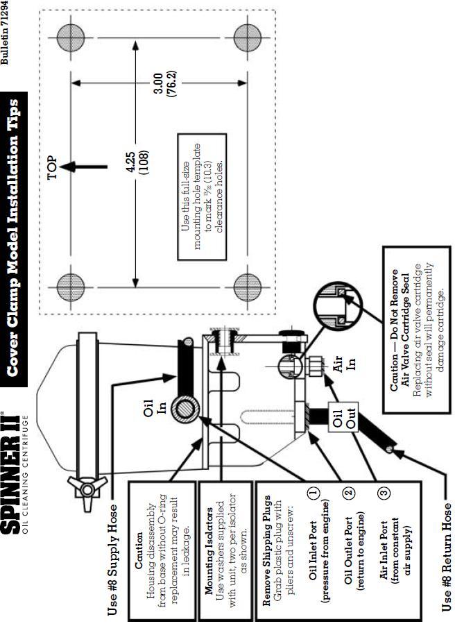
1 Centrifugal Filtration for Lubricants and Fluids Mining - Industrial - Marine - Agriculture - Automotive Model 996 Installation Instructions, Parts List and Service Instructions Three connections are required at the centrifuge: 1. Oil Inlet (3 4"- 16 UNF Female SAE J514-8 O-ring) - Unscrew plastic shipping plug. Run #8 hose from point of highest pressure. 2. Oil Outlet (3 4"- 16 UNF Female SAE J514-8 O-ring) - Unscrew plastic shipping plug. Run #8 hose to crankcase above oil level. 3. Air Inlet (1 4" NPT Female Pipe) - Unscrew plastic shipping plug. Run #4 hose from any convenient point on air supply to air valve cartridge inlet. Do not remove cartridge loss of cartridge seal will damage unit. CAUTION Route hoses to clear exhaust and all moving parts and fasten securely. Be certain pressure oil supply is to OIL IN port on side of centrifuge and return to crankcase is from OIL OUT port on bottom. Do not remove full-flow filters. Use the Spinner II centrifuge only as a by-pass oil cleaner. Remove any previously installed bypass filters prior to installation of the Spinner II, and block ports where necessary. Detailed Information Available For optimum performance of your centrifuge, specific installation drawings for most diesel engines can be requested from Westate Diesel Systems.

2 General Instructions Dirty Oil Supply to Centrifuge Oil Inlet Pressure Tap on Engine - Most engines, including the latest models from Cummins, Caterpillar, DDC and Mack, provide a 3 8" or 1 2" port to supply an auxiliary device. Avoid using end-of-gallery supply points such as the pressure gauge tap. Note on COV (Cut-Out Valve): Idle cut-out valve prevents oil flow into centrifuge at pressures less than 19 psig. Clean Oil Outlet Return to Crankcase Return Opening in Crankcase - Most engines have a 1 2" or larger oil return opening provided in the crankcase wall. If unrestricted, this is an ideal oil outlet line connection point. Special Return Problems - If there are no available drain openings, it may be necessary to drill and tap an inspection plate. Remove the plate before modification and avoid directing the return flow directly onto moving parts. Air Supply Air for the control mechanism can be taken from any convenient place on the vehicle air system where there is a constant supply of air, preferably from the dry tank. 1 8" nylon tubing is sufficient or #4 hose can be used if preferred. Air pressure can vary from 2 to 25 psig. No regulators, valves or control devices are required. The Spinner II control automatically shuts off the air supply when the engine stops SCFM air consumption is almost too small to measure. Mounting Location Install vertically ±10. The frame rail is the preferred location for mounting the centrifuge. A Spinner II Part spacer is available to facilitate inside frame rail mounting, requiring only two holes in the rail. Check with manufacturer before drilling. Below contains a drilling template. Additionally, a Spinner II Part No-Drill mounting bracket kit is also available. Use this kit when installation will not permit drilling of the frame rail. The Spinner II centrifuge is a high-speed device and is provided with noise isolators for operator comfort, which must be installed as shown above. Care should be used to prevent metal-to-metal contact with the frame or body, which might result in unnecessary noise or vibration. The cover clamp can be rotated to any convenient position and tightened by hand only. Cont.
3
4 1. Shut off engine and allow centrifuge turbine assembly (d) to come to a complete stop. 2. Loosen handle on clamp (b), disengage tee bolt and remove cover (a), using coin in gap to separate cover from housing. 3. Partially withdraw centrifuge turbine assembly (d) from the housing (e) and allow oil to drain from nozzles (o) before removing completely. Hold the centrifuge turbine assembly in one hand and loosen knurled bowl nut (h) several turns until the face of the nut projects beyond the bronze bushing face. Carefully separate centrifuge bowl (k) from turbine base (u) by striking the face of the nut (h) with the palm of one hand while holding the bowl in the other. Do not strike the nut or the bushing with or against a hard surface or damage will result. Finish removing the nut and then remove the bowl and baffle/screen (m). 4. Simply replace the dirty centrifuge bowl with a new one or carefully remove the dirt cake from the bowl (k) using a wooden spatula or other non-damaging tool. Wipe out bowl with solvent. Note: To save time in cleaning, an optional die-cut Bristol paper insert (l) is available as a service part and may be installed to allow the compressed cake to be removed quickly. 5. Wash and clean baffle/screen (m) and turbine base (u). Examine the Viton seal and replace, if damaged. The seal is Viton and can be reused several times. 6. Inspect top and bottom bushings of centrifuge turbine base (u). Replace turbine assembly if bushings show severe wear. Reassemble: Place baffle/screen (m) over stem of turbine body and seat evenly over shoulder on base. Install bowl seal (n) in recess in outer edge of turbine base. Slide a new centrifuge bowl (k) over stem and seat uniformly over bowl seal. Install and tighten knurled bowl nut (h) securely, using finger pressure only. 7. Inspect housing assembly (e) paying special attention to journal areas of spindle. Replace housing if damaged. 8. Clean and inspect cover (a). Always remove the old cover seal (c), clean the groove in the housing and mating surface of the cover. Examine the Viton seal and replace, if damaged. The seal is Viton and can be reused several times. 9. Check control mechanism (g) see diagram above. 10. Install centrifuge turbine assembly (d) on spindle. Be sure it rotates freely. Replace cover (a), position clamp (b) uniformly over cover and housing flanges, and tighten clamp handle securely by hand pressure only.
5 11. Remove, clean and inspect the idle cut-out valve assembly (s) and mating bore in housing. Correct any problems, renew seal (t) and replace assembly. 12. With the engine running, check all connections and joints for leaks. Trouble-Shooting Centrifuge removes too little dirt Check for Proper Operation Warm up engine and then bring engine to normal speed for one minute and immediately shut it down. If the Spinner II unit is working correctly the turbine can be heard spinning. As with any high-speed device, it may go through momentary periods of vibration as it passes through critical speeds while slowing to a stop. This is normal. If the turbine is not spinning or if vibration is severe or continuous at all speeds, an error may have been made in assembly. Repeat steps 1 to 10, paying special attention to the proper seating of baffle/screen (m), the bowl seal (n) (Step 6) and the control mechanism (Step 9). If vibration persists, substitute a different centrifuge turbine assembly (d). If the turbine is spinning properly, the centrifuge is doing its job of removing harmful abrasive dirt regardless of the amount of deposit found in the bowl. The visible deposit is largely soot and its thickness will vary from 1 16-in. to completely full depending on oil type, oil change interval, engine type and condition, and operating conditions. Control air valve problems Float valve flows air constantly or not at all, up or down. Air tank bleeds down overnight. Check Valve (Step 9) Most air control problems can be repaired without dismounting the centrifuge by renewing the air valve cartridge (q), making certain that air valve cartridge seal Part (r) is in place. A cartridge installed without the seal will be damaged and will leak continuously. If the float mechanism is worn or broken, the centrifuge must be disassembled and repaired with control float mechanism repair kit Part Instructions are contained in the kit. Caution: The valve cores in the air valve cartridge are special, low operating force-type with Viton seals to withstand hot oil. Do not substitute tire valve cores replace the entire cartridge. Oil leaks Cover Seal Remove cover (a) and cover seal (c). Clean seal grooves in housing and mating surface on cover. Install a new cover seal (b) in the housing groove, replace cover (a), position clamp (b) uniformly over cover and housing flanges, and tighten clamp handle securely by hand pressure only. Body to Control Mechanism Seal Remove cover and centrifuge turbine assembly. Remove control mechanism by loosening four cap screws. Discard seal (f) and clean groove and mating surfaces. Replace seal with a new one and retighten cap screws alternately to 35 lb-ft torque. It is possible to rotate the body 180 if it is necessary to locate the oil inlet port on the left side. Replace the seal and retighten bolts. Continue from Step 3 above. Oil Line Connections Disconnect leaking hose and remove hose adapter from port. Clean threads in port and on adapter, and inspect for damage. Reinstall adapter using a good liquid thread sealant. Reconnect hose. Made in England by Mann+Hummel (UK) Ltd. Patented worldwide. Viton is a registered trademark of E.I. DuPont de Nemours & Co., Inc. Spinner II is a registered trademark of T.F. Hudgins, Incorporated T.F. Hudgins, Incorporated. All rights reserved. Litho in U.S.A. Bulletin 73264/9-02
6 996 Service Instructions
Maintenance Information
 16573321 Edition 3 February 2014 Air Grinder Series 61H Maintenance Information Save These Instructions Product Safety Information WARNING Failure to observe the following warnings, and to avoid these
Installation Manual. Model T675A Engine Brakes. For Mack 6 Cylinder, 2 valve Head ENDT-673, 675, 676 & E6 Series Engines.
 Engine Brakes Installation Manual Model T675A Engine Brakes For Mack 6 Cylinder, 2 valve Head ENDT-673, 675, 676 & E6 Series Engines TecBrake P.O. Box 27822 Houston, Texas 77227 INSTALLATION MANUAL TECBRAKE
Maintenance Information
 Form 16573321 Edition 1 July 2004 Air Grinder Series 61H Maintenance Information Save These Instructions Always wear eye protection when operating or performing maintenance on this tool. Always turn off
Maintenance Information
 16572679 Edition 2 May 2014 Air Drill QP Series Maintenance Information Save These Instructions Product Safety Information WARNING Failure to observe the following warnings, and to avoid these potentially
Maintenance Information
 45528270 Edition 1 June 2007 Barring Motor T480 Series Maintenance Information Save These Instructions WARNING Always wear eye protection when operating or performing maintenance on this Barring Motor.
Maintenance Information
 04581245 Edition 2 May 2014 Air Grinder, Die Grinder and Sander Series G2 (Angle) Maintenance Information Save These Instructions Product Safety Information WARNING Failure to observe the following warnings,
MicroCoat. System Operating Manual MC2000 Series. MC785, MC785-WF Spray Valves. US: UK: Mexico:
 MicroCoat System Operating Manual MC2 Series MC785, MC785-WF Spray Valves A NORDSON COMPANY US: 8-498-8865 UK: 8 585733 Mexico: 1-8-556-3484 Introduction The MicroCoat System provides precise lubrication
Copper Sleeve, Unit Injector, Replacement
 Volvo Trucks North America Greensboro, NC USA This service bulletin replaces SB 237-46, Copper Sleeve, Unit Injector, Replacement dated 6.2007, publication no. PV776-20177417. DService Bulletin Trucks
Maintenance Information
 80234313 Edition 2 May 2014 Air Grinder, Die Grinder, Sander and Belt Sander Series G1 (Angle) Maintenance Information Save These Instructions Product Safety Information WARNING Failure to observe the
I & M 8000 Series. Ideal Installation Schematic. Preferred Installation. Trouble Shooting
 I & M 8000 Series 3170 Wasson Road Cincinnati, OH 45209 USA Phone 513-533-5600 Fax 513-871-0105 lowflow@richardsind.com www.lowflowvalve.com Installation & Maintenance Instructions for 8000 Series Low
Injector. General Information CAUTION. Use only the specified injector for the engine.
 Page 1 of 32 006-026 Injector General Information CAUTION Use only the specified injector for the engine. All engines use closed nozzle, hole-type injectors. However, the injectors can have different part
OPERATION, MAINTENANCE AND OVERHAUL INSTRUCTIONS FOR PB18 SERIES PORTABLE PUMPS
 WATEROUS COMPANY Form No. F 2058 South St. Paul, Minnesota 55075 January, 1992 OPERATION, MAINTENANCE AND OVERHAUL INSTRUCTIONS FOR PB18 SERIES PORTABLE PUMPS Printed in U.S.A. Waterous Company F 2058
2.- HANDLING OF VALVES BEFORE ASSEMBLY 3.- FITTING THE VALVE TO THE REST OF THE ASSEMBLY 5.- PERIODICAL INSPECTION OF THE VALVE AND MAINTENANCE
 Page 1 of 16 CONTENTS 1.- INTRODUCTION 2.- HANDLING OF VALVES BEFORE ASSEMBLY 3.- FITTING THE VALVE TO THE REST OF THE ASSEMBLY 4.- OPERATION OF A BALL VALVE 5.- PERIODICAL INSPECTION OF THE VALVE AND
Baumann Series Flexsleev Control Valve Instructions
 Instruction Baumann 86000 Series Instructions Baumann 86000 Series Flexsleev Control Valve Instructions Contents Introduction...1 Scope...1 Safety Precautions...1 Maintenance...2 Installation...3 Air Piping...3
Maintenance Information
 16573370 Edition 2 February 2014 Air Grinder 99V Series Maintenance Information Save These Instructions Product Safety Information WARNING Failure to observe the following warnings, and to avoid these
MicroCoat System Operating Manual MC4000 Series MC785M, MC785M-WF Spray Valves
 MicroCoat System Operating Manual MC Series MC785M, MC785M-WF Spray Valves A NORDSON COMPANY Introduction The MicroCoat System provides precise lubrication control for metal stamping operations. The MC
12 L * OH**
 Parts Manual Ersatzteil--Liste 12L27.. series 0.9 hp ERGO Short Coupled Low Profile Grinders & Sanders 45--8175 TOOL CLASSIFICATION 12 = ERGO Grinder/Sander 12 L 2 7 12 27 08* OH** -- TYPICAL MODEL THROTTLE
Maintenance Information
 45761848 Edition 3 February 2014 Air Die Grinder AC4A, SC4A and XC4A Series Maintenance Information Save These Instructions Product Safety Information WARNING Failure to observe the following warnings,
ANDERSON GREENWOOD SERIES 500 PILOT OPERATED SAFETY RELIEF VALVES INSTALLATION AND MAINTENANCE INSTRUCTIONS
 Before installation these instructions must be fully read and understood TABLE OF CONTENTS 1. General valve description and start-up... 1 2. Main valve maintenance... 1 3. Pilot maintenance... 5 4. Pilot
Baumann Way Control Valve
 Instruction Manual 24003 Valve Baumann 24003 3-Way Control Valve Contents Introduction... 1 Scope of Manual... 1 Safety Precautions... 2 Educational Services... 3 Maintenance... 3 Installation... 3 Air
Sentinel 250 Fire Hydrant
 Maintenance Instructions manual table of contents PAGE Sentinel 250 Fire Hydrant Inspection and Lubrication 2 Rotating Hydrant to Face Desired Direction 3 Installing Extension Section 3-6 Restoring Service
CP-1, CP-2, CP-2L & CPD-2 Series Overhaul
 Replacement of Mechanical Seals for CM, CMU, CS and CSU Series Pumps Installation Instructions Form No. F-1031 Section 5013 Issue Date 03/01/85 Rev. Date 02/08/11 CP-1, CP-2, CP-2L & CPD-2 Series Overhaul
4.2 WATER PUMP (GEAR CASE MOUNTED AND LATER) (GCM)
 (GCM)") SERIES 60 SERVICE MANUAL 4.2 WATER PUMP (GEAR CASE MOUNTED - 1991 AND LATER) (GCM) The centrifugal-type water pump circulates the engine coolant through the cooling system. The pump is mounted on the rear
SERIES 60 SERVICE MANUAL 4.2 WATER PUMP (GEAR CASE MOUNTED - 1991 AND LATER) (GCM) The centrifugal-type water pump circulates the engine coolant through the cooling system. The pump is mounted on the rear
This information covers procedures for replacing the sealant for the crankshaft cover on the Volvo D16F engine.
 Volvo Trucks North America Greensboro, NC USA DService Bulletin Trucks Date Group No. Page 1.2008 216 50 1(17) Sealant Crankshaft Cover, Replacement D16F Sealant Crankshaft Cover, Replacement W2005773
I & M Mark 78 Series. Ideal Installation. Start-Up. Installation & Maintenance Instructions for Mark 78 Control Valves (1-1/2-2 )
") I & M Mark 8 Series 0 Wasson Road Cincinnati, OH 4509 USA Phone 5-5-5600 Fax 5-8-005 info@richardsind.com www.jordanvalve.com Installation & Maintenance Instructions for Mark 8 Control Valves (-/ - ) Warning:
I & M Mark 8 Series 0 Wasson Road Cincinnati, OH 4509 USA Phone 5-5-5600 Fax 5-8-005 info@richardsind.com www.jordanvalve.com Installation & Maintenance Instructions for Mark 8 Control Valves (-/ - ) Warning:
INSTALLATION/OPERATION/MAINTENANCE INSTRUCTIONS FOR ARCHON MODELS WD2010L, WD2010, WD2010H WASHDOWN STATIONS. ARCHON Industries, Inc.
 ARCHON Industries, Inc. Washdown Stations Models WD2010L, WD2010, WD2010H Installation / Operation / Maintenance Instructions 1 This manual has been prepared as an aid and guide for personnel involved
Spring Return and Double Acting Pneumatic Quarter-turn Actuators Operations Manual
 Spring Return and Double Acting Pneumatic Quarter-turn Actuators Operations Manual Table of Contents General..................... 1 Pneumatic Recommendations... 1 Construction................. 2 Disassembly
ANDERSON GREENWOOD. Before installation these instructions must be fully read and understood.
 ANDERSON GREENWOOD Before installation these instructions must be fully read and understood. 1.1 General The Anderson Greenwood Series 200 Pilot Operated SRV uses the principle of pressurizing the larger
I & M Mark 78 Series. Ideal Installation. Start-Up. Installation & Maintenance Instructions for Mark 78 Control Valves (1/2-1 )
") I & M Mark 8 Series 30 Wasson Road Cincinnati, OH 4509 USA Phone 53-533-5600 Fax 53-8-005 info@richardsind.com www.jordanvalve.com Installation & Maintenance Instructions for Mark 8 Control Valves (/ -
I & M Mark 8 Series 30 Wasson Road Cincinnati, OH 4509 USA Phone 53-533-5600 Fax 53-8-005 info@richardsind.com www.jordanvalve.com Installation & Maintenance Instructions for Mark 8 Control Valves (/ -
Fuel Pump ( ) Table of Contents. Summary. View Related Topic. Summary. General Information Test. Preparatory Steps. Remove.
 Table of Contents. Summary. View Related Topic. Summary. General Information Test. Preparatory Steps. Remove.") View Related Topic Fuel Pump (005-016) Table of Contents Summary General Information Test Without Electric Lift Pump With Electric Lift Pump Preparatory Steps Marine Applications Remove Rear Gear Train
View Related Topic Fuel Pump (005-016) Table of Contents Summary General Information Test Without Electric Lift Pump With Electric Lift Pump Preparatory Steps Marine Applications Remove Rear Gear Train
CUSTOM COMBINATION AIR VALVE
 INSTALLATION / OPERATION / MAINTENANCE CUSTOM COMBINATION AIR VALVE INTRODUCTION This manual will provide you with the information to properly install and maintain this valve to ensure a long service life.
PRODUCT SERVICE MANUAL
 PRODUCT SERVICE MANUAL FOR AM322ICX-325AE, 350AN and 400A PUMPS WARNING This Special Instruction Manual and General Instructions Manual, SRM00046, should be read thoroughly prior to pump installation,
SERVICING INSTRUCTIONS
 TSP Series 66 Triplex Plunger Pump SERVICING INSTRUCTIONS TRIPLEX TRIPLEX SERVICING PUMP PROCEDURES Valve Replacement: All inlet and discharge valves can be serviced without disrupting the inlet or discharge
BMK-30. Heavy-Duty By-Pass Filtration System Installation and Servicing Instructions
 BMK-30 Heavy-Duty By-Pass Filtration System Installation and Servicing Instructions IMPORTANT NOTICE Read all instructions completely before attempting to install this unit. Improper installation could
Maintenance Information
 16572554 Edition 2 May 2014 Air Drill 44SMA, 44SMA-EU Maintenance Information Save These Instructions Product Safety Information WARNING Failure to observe the following warnings, and to avoid these potentially
Maintenance Information
 80234313 Edition 1 June 2006 Air Grinder, Die Grinder, Sander and Belt Sander Series G1 (Angle) Maintenance Information Save These Instructions WARNING Always wear eye protection when operating or performing
Four Wheel Drive Kit Groundsmaster 580D
 Four Wheel Drive Kit Groundsmaster 580D FORM NO. 957 Rev B Model No. 0599 00 thru 99999 INSTALLATION INSTRUCTIONS POTENTIAL HAZARD Traction Unit rolls over. WHAT CAN HAPPEN Bodily injury could occur. 4
Model DF269 Control Valve
 Figure 1 DF269 Control Valve TABLE OF CONTENTS Introduction 2 Fail Open Actuator Disassembly 6 General 2 Body and Packing Reassembly 7 Scope 2 Fail Closed Actuator Resassembly 8 Specifications 3 Fail Open
Maintenance Instructions
 General Note These instructions contain information common to more than one model of Bevel Gear Drive. To simplify reading, similar models have been grouped as follows: GROUP 1 Models 11, 0, 1,, (illustrated),,
MUELLER GAS. No-Blo Valve. Changers. Reliable Connections. General Information 2-3. Plugging Unit Assembly 4-5. Removing Old Valve 5-6
 operating Instructions manual MUELLER GAS TAble of contents PAGE No-Blo Valve General Information 2-3 Plugging Unit Assembly 4-5 Removing Old Valve 5-6 Installing New Valve 6-7 Changers! WARNING: 1. Read
PRESSURE RELIEF VALVE: DISASSEMBLY, INSPECTION, and ASSEMBLY CONTENTS
 Page 1 of 35 PRESSURE RELIEF VALVE: DISASSEMBLY, INSPECTION, and ASSEMBLY CONTENTS 1. Overview 2. Disassembly of Valves with Liner Subs and press-in Bushing (Models 30525 and 30550). 2.1. Routine Disassembly
WARNING. Filter Service. Section Refer to the following pages for timing and procedures of fi lter element replacement.
 Section 10-1 Filter Service Effective fi ltration of fl uids is vital to the longevity and performance of your Wagner. See the previous section on Preventive Maintenance for the scheduled intervals for
I & M Mark 708. Ideal Installation. Start-Up Procedure. Installation & Maintenance Instructions for Mark 708 & 14M Actuator and Motor Valve
 I & M Mark 708 370 Wasson Road Cincinnati, OH 509 USA Phone 53-533-5600 Fax 53-87-005 info@richardsind.com www.lowflowvalve.com Installation & Maintenance Instructions for Mark 708 & M Actuator and Motor
Installation Guidelines
 JUSV4-K (metal lever handle) & GUSVR (rough) JUSV4-K (white porcelain lever handle) & GUSVR (rough) JUSV43-K (black porcelain lever handle-mto) & GUSVR (rough) 5 " Shower Outlet Tub Outlet 3 "± " IMPORTANT
Installation Manual. Model T680A/B Engine Brakes. For Mack 6 Cylinder, 4 Valve Head E6 and E7 Series Engines. Engine Brakes
 Engine Brakes Installation Manual Model T680A/B Engine Brakes For Mack 6 Cylinder, 4 Valve Head E6 and E7 Series Engines TecBrake P.O. Box 27822 Houston, Texas 77227 INSTALLATION MANUAL TECBRAKE T680A
Actions Required to Avoid Repeat Turbocharger Failures
 SERVICE BULLETIN (Also applies to Mack Trucks Australia) (Supersedes SB214020 dated 7/26/04) Number: SB214020 Date: 07/21/05 Model: ASET, E-Tech Actions Required to Avoid Repeat Turbocharger Failures When
JRC ENGINEERING INC 3110 Indian Ave Suite E Perris, California
 JRC ENGINEERING INC 3110 Indian Ave Suite E Perris, California 92571 800-634-3250 Thank you for choosing our 750 conversion for your Triumph 650. Careful assembly and running in will greatly extend the
Maintenance Information
 16575128 Edition 2 May 2014 Air Grinder, Sander or Polisher 77A Series Maintenance Information Save These Instructions Product Safety Information Failure to observe the following warnings, and to avoid
Service Bulletin Published by Sudden Service, Inc.
 Service Bulletin Published by Sudden Service, Inc. Volume 18 / Number 2 / February 1, 2018 Louisville, Mississippi Preventative Maintenance (PM) Requirements for Diesel Engines Equipped With EPA Tier 4
Section Periodic Inspection and Lubrication (At First 25 Hours, First 50 Hours, First 100 Hours and Subsequently at 100-Hour Intervals)
") Airmaster Propellers Ltd Variable Pitch Constant Speed Propellers for Light Aircraft Airmaster Propellers Ltd Unit B, 144 Central Park Dr PO Box 21220, Henderson Auckland, New Zealand Ph: +64 9 8360065
Airmaster Propellers Ltd Variable Pitch Constant Speed Propellers for Light Aircraft Airmaster Propellers Ltd Unit B, 144 Central Park Dr PO Box 21220, Henderson Auckland, New Zealand Ph: +64 9 8360065
Tillotson Tc3A Carburator
 Tillotson Tc3A Carburator 176 FUEL SYSTEMS - 5B-11 CENTER BOWL TYPE CARBURETOR Removal 1. Remove front cowl cover and wrap-around cowl. 2. Remove swivel link from lower carburetor. (Figure 2) 3. Loosen
SERVICE MANUAL 200 SERIES MOTORIZED 20352, 20452, 20551, 20552, AND MODELS
 Section: MOYNO 500 PUMPS Page:1 of 4 Date: March 1, 1998 SERVICE MANUAL MOYNO 500 PUMPS 200 SERIES MOTORIZED 20352, 20452, 20551, 20552, 22051 AND 22052 MODELS DESIGN FEATURES Housing: AISI 316 stainless
Model DF233 Control Valve
 Figure 1 DF233 Control Valve TABLE OF CONTENTS Introduction 2 Body and Packing Reassembly 7 Specifications 3 Fail Closed Actuator Reassembly 8 Valve Sizes 3 Fail Open Actuator Reassembly 9 Unpacking 4
Sachs 48mm Closed Cartridge fork Service Manual
 Sachs 48mm Closed Cartridge fork Service Manual 1 Fork seal driver 2 Special soft jaws 3 Fork cap wrench 4 Rebound rod holding tool 5 Compression assembly holding tool 6 Retaining clip tool Special Tools
AJV8 Engine Assembly. AJV8 Engine Assembly
 AJV8 Engine Assembly Contents Cylinder Block Dowels, Plugs and Pipes 2 4 Crankshaft Bearing and Cylinder Bore Dimensions 5 9 Bearing Measuring 6 Engine Dimensions and Codes 6 7 Main Bearing Selection Chart
PRODUCT SERVICE MANUAL. BK6DHZ(C)-250, 275, 312 and 400 PUMPS
-250, 275, 312 and 400 PUMPS") PRODUCT SERVICE MANUAL BK6DHZ(C)-250, 275, 312 and 400 PUMPS WARNING This manual, and the GENERAL INSTRUCTION MANUAL, SRM00046, should be read thoroughly prior to pump installation, operation or maintenance.
PRODUCT SERVICE MANUAL BK6DHZ(C)-250, 275, 312 and 400 PUMPS WARNING This manual, and the GENERAL INSTRUCTION MANUAL, SRM00046, should be read thoroughly prior to pump installation, operation or maintenance.
Finishing Mower Estate 72
 Finishing Mower Estate 72 Owners/Operators Manual & Spare Parts List Issue Date: October 2011 1 Introduction Your FIELDMASTER Estate 72 Finishing Mower has been designed to do a range of work to your satisfaction.
I & M Mark 708ME. Ideal Installation. Start-Up Procedure. Installation & Maintenance Instructions for Mark 708 & Motor Actuator
 I & M Mark 708ME 3170 Wasson Road Cincinnati, OH 45209 USA Phone 513-533-5600 Fax 513-871-0105 info@richardsind.com www.lowfl owvalve.com Installation & Maintenance Instructions for Mark 708 & Motor Actuator
Paint/Solvent/Dump Valve and Flow-Through Valve
 Instruction Sheet P/N 08573D Paint/Solvent/Dump Valve and Flow-Through Valve. Description See Figure. The paint/solvent/dump valve is a normally-closed valve that opens to trigger and/or dump coating material.
250L Cartridge Dual Seal
 INSTALLATION, OPERATION AND MAINTENANCE INSTRUCTIONS 250L Cartridge Dual Seal Installation, Operation and Maintenance Instructions TABLE OF CONTENTS 1.0 Cautions...2 2.0 Transport and Storage...2 3.0 Description...2
M-5000TG/5700TG Steam and Cold Water Mixing Unit
 M-5000TG/5700TG Steam and Cold Water Mixing Unit Installation, Operating and Maintenance Instructions Last Updated: October, 2012 Strahman Valves, Inc. USA Headquarters 2801 Baglyos Circle Bethlehem, PA
OPERATION AND PARTS MANUAL
 OPERATION AND PARTS MANUAL MODEL NUMBER : PART NUMBER : TAP- IN KIT 5100-5151 BAYNE MACHINE WORKS, INC. PHONE: (864) 288-3877 910 FORK SHOALS ROAD TOLL FREE: (800) 535-2671 GREENVILLE S.C., 29605 FAX:
Binks MODELS & AGITATOR DRIVE UNITS
 Binks MODELS 31-393 & 31-394 AGITATOR DRIVE UNITS for Agitator Equipped Drum MODEL 31-393 Includes the following items: 1, 2, and 3. 1 MODEL 31-394 shown. 17 4 3 2 12 13 14 15 2 3 8 5 9 11 8 10 6 7 17
Fluid-O-Tech ROTOFLOW ROTARY VANE PUMP REBUILD MANUAL
 Fluid-O-Tech PUMP TECHNOLOGY AT ITS BEST WWW.FLUID-O-TECH.COM Office: 161 Atwater St., Plantsville, CT 06479 Phone: (860) 276-9270 Fax: (860) 620-0193 ROTOFLOW ROTARY VANE PUMP REBUILD MANUAL 08/09 Ed.,
Instruction Manual & Parts List For H/G323FXFSX-500_ & 800_ Pumps With Flowserve Type BX Cartridge Seal
 TM Instruction Manual & Parts List For H/G323FXFSX-500_ & 800_ Pumps With Flowserve Type BX Cartridge Seal WARNING This Special Instruction Manual and General Instructions Manual, CA-1, should be read
Input Adjusting Ring Leak Repair Procedure for Meritor MT-14X Series Forward Differential Carriers
 Revised 01-16 Technical Bulletin Input Adjusting Ring Leak Repair Procedure for Meritor MT-14X Series Forward Differential Carriers Revised 1 Technical 01- Bulletin 16 Hazard Alert Messages Read and observe
Anderson Greenwood Series 800 POSRV Installation and Maintenance Instructions
 Before installation these instructions must be fully read and understood Table of contents 1. General valve description and start-up... 1 2. Main valve maintenance... 2 3. Pilot maintenance... 6 4. Pilot
M-5000TG/5700TG Steam and Cold Water Mixing Unit
 M-5000TG/5700TG Steam and Cold Water Mixing Unit Installation, Operating and Maintenance Instructions Last Updated: August, 2014 Strahman Valves, Inc. USA Headquarters 2801 Baglyos Circle Bethlehem, PA
Installation Instructions
 Suzuki Samurai 1 Inch and 2 Inch Body Lift Kit (SKU# SSP-BL) Installation Instructions Background: These instructions are designed for installing the 2 body lift. Our approach is to raise the entire body
MODELS 3100,3130,3160, 1300, 1330,1360 EXHAUST SYSTEM
 MODELS 3100,3130,3160, 1300, 1330,1360 EXHAUST SYSTEM WALBRO CARBURETOR "WA" SERIES MUFFLER REMOVAL CARBURETOR REMOVAL The muffler assembly should beremoved periodically to inspect for excessive carbon
OWNER S TECHNICAL MANUAL
 OWNER S TECHNICAL MANUAL 2.5kg Grease Kit 6336 Description The Champion 6336 2.5kg grease kit is a manually operated, spring powered grease kit that comes complete with a hand piece. It is designed to
OWNER S TECHNICAL MANUAL. 6336N 2.5kg Grease Kit
 OWNER S TECHNICAL MANUAL 6336N 2.5kg Grease Kit 6336N Description The 6336N 2.5kg grease kit is a manually operated, spring powered grease kit with ergonomic, user friendly rod cap that comes complete
Fisher 1061 Pneumatic Piston Rotary Actuator with Style H & J Mounting Adaptations
 Instruction Manual 1061 H & J Actuator Fisher 1061 Pneumatic Piston Rotary Actuator with Style H & J Mounting Adaptations Contents Introduction... 1 Scope of Manual... 1 Description... 2 Specifications...
Maintenance & Repair Manual
 SM64055 November 2012 Aerospace Group Conveyance Systems Division Applicable additional manuals: None Carter Brand Ground Fueling Equipment Maintenance & Repair Manual 4 Inch Internal/Bottom Loading Valves
When installing the screwed end, socket weld & flanged end valves the following respective procedures shall be followed for better performance.
 1. Storage LARSEN & TOUBRO LIMITED Page 1 of 5 1.1. All valves are to be stored in fully open position, in order to protect the sphere surface and soft valve seats. 1.2. Before shipping, the inlet and
Service Handbook HD /97
 Service Handbook HD 1050 5.905-032 07/97 Foreword HD 1050 Foreword Indispensable prerequisites for the competent execution of service procedures are comprehensive, real-life training workshops for technical
PRODUCT SERVICE MANUAL FOR BK12DHZ PUMPS
 PRODUCT SERVICE MANUAL FOR BK12DHZ PUMPS WARNING This manual, and the GENERAL INSTRUCTION MANUAL SRM00046, should be read thoroughly prior to pump installation, operation or maintenance. Manual No. SRM00095
CONTROL VALVES SINGLE PORTED CLASSES DL, DDL, DOS, DDOS
 12501 Telecom Drive, Tampa Florida 33637 Installation, Operation and Maintenance 10/1.5.1 Rev. 0 CONTROL VALVES SINGLE PORTED CLASSES DL, DDL, DOS, DDOS TABLE OF CONTENTS INSTALLATION...2 VALVE POSITION...2
Maintenance Information
 16606022 Edition 3 May 2014 Air Drill 728 Series Maintenance Information Save These Instructions Product Safety Information WARNING Failure to observe the following warnings, and to avoid these potentially
Models & & 4 Air Operated Bypass Pressure Control Valves SM64501
 SM64501 September 2008 Aerospace Group Conveyance Systems Division Carter Brand Ground Fueling Equipment Applicable addition manuals: None Maintenance & Repair Manual 3 & 4 Air Operated Bypass Pressure
Installation Instructions
 Preparing your vehicle to install your brake system upgrade 1. Rack the vehicle. 2. If you don t have a rack, then you must take extra safety precautions. 3. Choose a firmly packed and level ground to
CHESTERTON FLOW GUARDIAN S50 AND SP50 SINGLE FLOWMETER INSTALLATION INSTRUCTIONS
 INSTALLATION INSTRUCTIONS CHESTERTON FLOW GUARDIAN S50 AND SP50 SINGLE FLOWMETER INSTALLATION INSTRUCTIONS GENERAL The function of the FLOW GUARDIAN Single S50 (Item # 199801 compression fitting, 199804
WARNING Carefully Read These Instructions Before Use
 DO NOT RETURN THIS SPRAYER TO STORE Call: 1-800-950-4458 Backpack Sprayer Use and Care Manual Manufactured for Northern Tool + Equipment Co., Inc. WARNING Carefully Read These Instructions Before Use Model
Operating & Maintenance Manual For Steam Conditioning Valve
 For Steam Conditioning Valve 1 Table of Contents 1.0 Introduction 3 2.0 Product description 3 3.0 Safety Instruction 4 4.0 Installation and Commissioning 5 5.0 Valve Disassembly 6 6.0 Maintenance 6 7.0
NSGV EVE-ER I, O, & M MANUAL
 TABLE OF CONTENTS Rail Layout.. Page 1 Support Placement...Page 1 Rail Assembly.Page 1 Rail Duct Connections.. Page 2 Rubber Lip Installation.. Page 3 Pneumatic End Stop. Page 4 End Stop. Page 4 End Cap..
DESCRIPTION MAINTENANCE
 Specifications Information and Repair Parts Manual 316F-95 and 316F-99 Please read and save this Repair Parts Manual. Read this manual and the General Operating Instructions carefully before attempting
Maintenance Information
 16596199 Edition 2 May 2014 Air Drill 33 Series Maintenance Information Save These Instructions Product Safety Information WARNING Failure to observe the following warnings, and to avoid these potentially
SPECIFICATIONS TEST AND ADJUSTMENT SPECIFICATIONS SPECIFICATIONS ENGINE FD620D, K SERIES
 ENGINE FD620D, K SERIES SPECIFICATIONS SPECIFICATIONS TEST AND ADJUSTMENT SPECIFICATIONS Engine Oil Pressure Sensor Activates............................... 98 kpa (14.2 psi) Oil Pressure While Cranking
Remove Air Cleaner Cover and. Filter
 Remove Air Cleaner Cover and Inspect paper filter for tears Foam pre-cleaner is washable if equipped Replace if necessary Filter Remove Trim Panel Pull throttle lever knob off Remove 3, 8mm screws Remove
MAINTENANCE MANUAL FOR THERMOSTATIC TEMPERATURE REGULATING VALVE TRAC STYLE P
 MANUAL NUMBER P-EFS-1 MAINTENANCE MANUAL FOR THERMOSTATIC TEMPERATURE REGULATING VALVE TRAC STYLE P TRAC Regulator Company Inc. 160 South Terrace Avenue Mount Vernon, New York USA 10550-2408 Phone: (914)
Maintenance Information
 16573347 Edition 2 February 2014 Air Grinder Series 88H Maintenance Information Save These Instructions Product Safety Information WARNING Failure to observe the following warnings, and to avoid these
½" to 4" (DN15 to DN100) LEA31 and LEA33 ANSI Control Valves Installation and Maintenance Instructions
 LEA31 and LEA33 ANSI Control Valves Installation and Maintenance Instructions") 00050/1 IM-P0-02 CH Issue 1 ½" to " (DN15 to DN100) LEA1 and LEA ANSI Control Valves Installation and Maintenance Instructions 1. Safety 2. Technical details. Installation and commissioning. Maintenance
00050/1 IM-P0-02 CH Issue 1 ½" to " (DN15 to DN100) LEA1 and LEA ANSI Control Valves Installation and Maintenance Instructions 1. Safety 2. Technical details. Installation and commissioning. Maintenance
Fisher D2T FloPro Control Valve
 Instruction Manual D2T FloPro Valve Fisher D2T FloPro Control Valve Contents Introduction... 1 Scope of Manual... 1 Description... 1 Educational Services... 2 Specifications... 3 Installation... 3 Setting
TILLOTSON LTD., CLASH INDUSTRIAL ESTATE, TRALEE, CO. KERRY, IRELAND PHONE: FAX:
 TILLOTSON LTD., CLASH INDUSTRIAL ESTATE, TRALEE, CO. KERRY, IRELAND PHONE: +353 66 7121911 FAX: +353 66 7124503 e-mail: sales@tillotson.ie SERIES SERVICE MANUAL INTRODUCTION The gasoline engine industry
CAUTION. 2. Remove the wheel cover or nut covers, as required. Remove the wheel and tire assembly.
 Стр. 1 из 16 REAR DRUM BRAKES CAUTION Brake shoes may contain asbestos, which has been determined to be a cancer causing agent. Never clean the brake surfaces with compressed air! Avoid inhaling any dust
MAINTENANCE CLEANING. MECHANICAL SEAL REPLACEMENT Refer to figures 1 and 2. SHIM ADJUSTMENT
 Please read and save this Repair Parts Manual. Read this manual and the General Operating Instructions carefully before attempting to assemble, install, operate or maintain the product described. Protect
Housing (Front) - Remove
 - Remove") SENR9978-01 63 1. Lift the assembly (3) of the idler gear and the hub over the housing for the crankshaft front seal (2) and insert the hub into the recess in the cylinder block. Refer to illustration
SENR9978-01 63 1. Lift the assembly (3) of the idler gear and the hub over the housing for the crankshaft front seal (2) and insert the hub into the recess in the cylinder block. Refer to illustration
Service Handbook High-Pressure Washer Pump
 Service Handbook High-Pressure Washer Pump 9.120-014.0 2 A. Water Inlet Filter C. Nozzle Insert 1. Remove filter with a screwdriver. 2. Clean filter with warm water and mild soap. 3. Reinstall filter.
INSTALL MANUAL. FOR ON LINE ORDERING- E Commerce Visit Our Website
 INSTALL MANUAL FOR ON LINE ORDERING- E Commerce Visit Our Website WWW.PRESSUREGUARD.COM Contact Information Technical Support: Chris@pressureguard.com Sales Support: Sales@pressureguard.com By Phone: 615-227-6024
3M Overhaul Service Kit
 SERVICE INSTRUCTIONS FOR 3M 12,000 RPM 3 in. (77 mm) RANDOM ORBITAL SANDERS 3M Overhaul Service Kit The part number 20346, 3M Overhaul Service Kit, contains all the replacement parts that naturally wear