S1 R35 GT-R Install Guide
|
|
|
- Clarence Griffin
- 5 years ago
- Views:
Transcription


1 S1 R35 GT-R Install Guide


2 1. Quick Start Guide Aeromotions recommends professional installation of the S1 Wing. If the wing was professionally installed, here s what you need to know to use it. The wing has three angles: Braking, cornering, and straightaway. 1. The Braking angle is high downforce and high drag for maximum stopping power. 2. The Cornering angle should be set to provide the level of downforce needed to balance the car at the traction limit in a turn. The correct angle is dependent on car setup, and should be adjusted by holding down the CORNERING button and using the UP and DOWN arrow keys. 3. Straightaway is set for low drag. You can increase this angle if you want more stability at high speed. 2. Tuned for your GT-R The Computational Fluid Dynamic (CFD) model of the GTR, shown below, will let you see how the air flows around the GT-R. It s worth noting that the air follows the rear window of the car, approaching the wing at a downward angle. This apparent angle of attack means the wing feels a higher angle of attack than you would measure with a level (which assumes the air is coming straight on). This is why your wing has a maximum stall angle of 7.4 degrees when mounted on the GTR (instead of the 14.2 degrees of the wing by itself).

3 Tuning Cornering Angle This graph gives the maximum downforce as a function of speed for the Nissan GTR at 7.4 degrees The cornering angle should be adjusted based on the front aero on your GTR. The Aeromotions wing features a high performance airfoil. With an Aeromotions wing, small wing angles produce much more downforce than standard wings at the same angle. When tuning on a new car, the goal is to get the rear aero (wing, diffuser, etc) to balance the front aero (splitter, canards, etc). As a rule of thumb, a 30-60mm front splitter should start with 2-3 degrees of wing angle, and increase 1 degree at a time. As the below graph shows, the effect of the wing will increase with the square of speed. Low speed handling is dominated by tires and suspension, high speed handling is dominated by aero. The crossover point is somewhat unique to each car and setup.
4 3. Wiring Connections on the Dynamic Module Power Cable The Dynamic Module requires 10Amp switched power. +12V should be applied to the red wire. The Black wire is ground. Data Cable ( 3 wire connector) VSS o The Blue wire connects to the vehicle VSS wire. o Connect the VSS wire from the GTR Navigation as described below.. o For a stand alone ECU, the output signal should be: A square wave (OC) 0-5V or 0-12V See below for setting pulses per mile o The black wire is an extra ground wire, it can be left disconnected or may be used with some standalone ECU s o A sine-wave output from a hall effect sensor will not work. Data Logging o An optional Analog Output Cable is available for purchase from Aeromotions to output the wing angle as an analog voltage from 0-5V. If that cable is being used, the Red wire is the output for the Setting the Vehicle Speed Sensor The Pulses Per Mile (PPM) that the ADAPT Controller reads from the vehicle is programmable in wings sold after March The PPM only has to be set once, then is stored in the ADAPT Controller. To set the PPM, Power On the ADAPT Controller while depressing the SPEED SET Button. A single LED on the 10 LED Bar display will be illuminated to indicate which PPM is selected as shown in the table below: LED PPM VEHICLE 1 3,600 CAN Adapter 2 4,000 EVO and Corvette 3 8,000 GT-R 4 10, ,056 Porsche Use the UP and DOWN arrow keys while depressing the SPEED SET Button to select the PPM for your car. For example, for a GT-R, the 3 rd LED would be lit. Powering OFF the ADAPT Controller will return it to normal operation and it will remember which PPM you selected.
5 2012+ GTR Vehicle Speed Sensor (VSS) CAN Adapter Color I/O Function Black I Ground Red I Power +12V regulated ignition controlled supply Yellow I CAN High Blue I CAN Low Orange O Speed Pulse Output 12V Connect the Orange output wire to the Blue VSS wire The CAN Adapter has built-in diagnostic LEDs to indicate CAN Bus status and speed pulse output to aid the installation process. After power-up: Stage 1: Both LEDs light for approx 1 second Stage 2: Green LED on while the CB-1 listens for CAN Bus data Stage 3: Red LED indicates CAN has been detected. CB-1 now detecting vehicle type Stage 4: Once vehicle type is determined the Green LED should pulse when vehicle is driven. Red LED should stay on. Please note: If LEDs do not follow the above sequence it is still advisable to drive the vehicle to see if a speed pulse signal is still actually being produced by the CB-1. It is possible that some vehicles will perform in a different manner.
6 General Installation Notes The CAN Bus uses two wires for data transmission. One is called CAN_HIGH and the other called CAN_LOW (sometimes marked as CAN+ and CAN- respectively). All connections should be made with an insulated solder joint. Do not cut the CAN Bus wires. IMPORTANT NOTICE: All connections are for guidance only and to the best of our knowledge. We cannot be held responsible for changes made by the vehicle manufacturer. The CAN Bus system is growing in use by American and European vehicle manufacturers. Unfortunately, they do not conform to anyone standard or wiring concept. Colors can vary as well as location and layout of ECU's. In addition, a vehicle can have more than one CAN Bus system, with potentially only one set carrying the speed pulse data. It is also advisable to disconnect the CAN I SCP interface before any diagnostic work is carried out on the vehicle. This will prevent any possible damage to the interface and also allow any diagnostic work to be carried out successfully. 1. Since manufacturers continually change the pin configuration of the plugs, it is advisable to pick up Pos and Neg for powering the interface from an alternative supply, preferably a good ignition controlled regulated supply. A good earth is essential. 2. The CAN Bus interface has such high internal impedance that it cannot affect the vehicle operation. 3. Connect the CAN High and CAN Low wires before powering up the CB1 interface, so removing any possibility of shorting. While the power wires can be extended, it is not advisable to extend the CAN High and Low leads. If there is a need to extend the signal lead (Orange), please ensure that it is run to its destination avoiding being close to equipment that might give off pulses which could be picked up by this wire, such as ignition or heater fans, etc. OBD II Plug GTR Vehicle Speed Sensor (VSS) The VSS provides the vehicle speed to the computer. The VSS is tapped from the dash behind the navigation console. First remove the center console near the passenger seat. It pulls straight out near the center and slides back near the front.


7 Behind the DVD head unit, there is a WHITE plug with 20+ positions. From the rear of the unit, it would be on the top left corner. From your passenger side view, it s the closest to you on top. Near the center of the TOP of the plug, is a red power line, right next to that is a VIOLET line. The violet line is the VSS wire. Note, Australian, and British GT-R s have a light green VSS wire. \ VSS

8 Australian VSS wire, Light Green, in the same location as the USDM VSS.
9 GT-R Power Power can be tapped off an existing 10A switched line, or run as a switched relay from the battery. Tapping into the switched power. There is a 10 amp switched cigarette receptacle toward the back of the center arm rest. This can be tapped to supply the power for the wing. This circuit is already switched and fused. At track speeds, the wing will require all 10 amps, in which case, you should not use the cigarette lighter to power any other accessories. Unplug phone chargers or any additional power draws for track use. The cigarette lighter can be pulled forward through the console in which it is mounted. Doing so will prevent substantial disassembly of the console. The power can be tapped here, and run back through the hole the cigarette lighter came out of. Running power from the battery. The battery is on the right side of the engine compartment. There is a small rubber stopper behind the battery that goes directly into the cabin. Pull the side panel (lower right passenger side, one plastic thumb screw, then pull panel in towards car evenly - it pops out). Behind that and UP is the ECU and wiring harnesses. Looking farther up and toward the front firewall you will see the hole from the removed stopper.


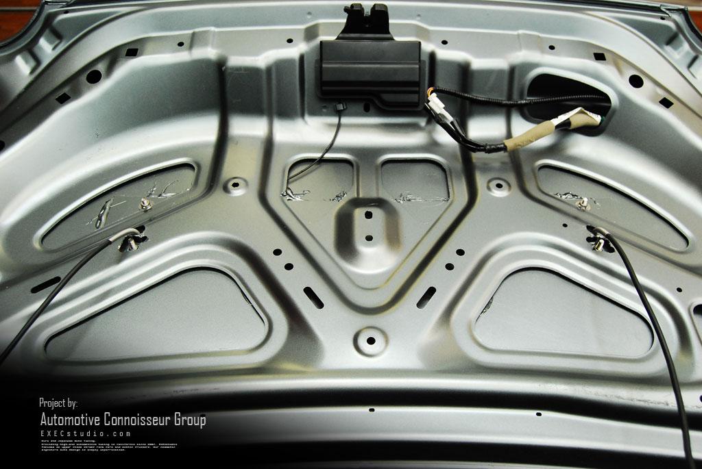
10 4. The Control Box Mounting The control box should be mounted to the deck lid, as shown bellow. The writing should be facing the correct direction when the deck lid is up.

11 S1 Controller with CF trunk mounting adapter rails
 to the wing.")
12 4. Assembling the Wing The following steps describe how to assemble the wing prior to mounting it to the car. 1. Mount the front pivot of each power pod to the S1 wing. Note that the bottom of each power pod is cut at an agle to match either the left or right side of the deck lid. 2. Mount the rear control arm of the right power pod (passenger side) to the wing. DO NOT MOUNT THE LEFT CONTROL ARM YET. The right control arm will set the wing angle. The left power pod will be flexible, and able to rotate. 3. Mount the wing to the deck lid using the instructions below. 4. After both of the power pods are firmly attached to the deck lid, the left control arm will be attached to the wing. 5. Power the wing on, with the deck lid closed. 6. Unscrew the left rod end until the eyelet hole lines up with the black wing support hole. This will ensure both halves are balanced. 7. Insert the rear shoulder bolt in the left power pod half. (In rare circumstances, the left rod end will be above the pivot hole. In this case, unscrew the right rod end until the left end lines up with the mounting hole). 8. Attach the End Plates using the M5 screws (Max Torque 4 N-m). 5. Mounting an S1 Wing on the R35 In order to use the stock GTR tune, the wing needs to be mounted in the correct position. The S1 wing mounts with four M6 studs that are permanently mounted to the bottoms of the Power Pods. These can be cut to length. The electrical cables that run to each power pod have a connector (shown in blue) that needs a clearance hole to pass into the trunk. 5.1 Trunk Options Aeromotions Carbon Fiber Trunk The Aeromotions R35 carbon fiber trunk comes pre-drilled with all the necessary mounting holes for the wing and computer. The trunk can be ordered directly from AMS amsperformance.com/


13 Nissan OE Trunk S2 Mounted on Trunk The OE trunk must be reinforced substantially to securely hold the wing. Bracing needs to be installed span wise in order to take the downforce of the wing. See pictures on next page. The black aluminum uprights have carbon shells, feet, that adapt the wing to the trunk. These feet should fit snugly into the bottom of the aero tube. The rear tip of each foot should be 5 1/2 inches from rear lip of the trunk. Once positioned, three holes should be drilled per upright. Two are clearance holes for the M6 studs, the third is for the power cable. The three holes are the same as the holes drilled in the carbon fiber feet. The drawing below (available as pdf drawing W , Sheet 1) shows the mounting pattern in the top of the trunk. The six holes shown in this drawing should be through holes to accommodate the M6 Studs (4 x Ø.25) and the connectors (2 x Ø.63)
14

15
16 User Manual: Dynamic Wing S1 1. Dynamic Wing S1 The S1 Dynamic Wings come with a plug and play tune specifically developed for your car. The controller will automatically provide ample downforce in corners, more when you brake, and lower drag on the straightaway. The wing is programmed with angles tuned for your car. Braking Angle o The wing moves to this high downforce, high drag angle during braking. Maneuvering Angle (Low Speed Cornering) o This is the default wing angle. The wing at this position when the car is standing still, or cornering. Increasing or decreasing this angle will change the car s balance in corners. High Speed Maneuvering Angle (High Speed Cornering) o This angle allows a different maneuvering angle to be set for high speeds. Straightaway Angle o The wing moves to this low drag angle when it detects the car is on a straightaway. Note, each racecar setup is unique. Dynamic Wings are programmed to work with the stock upper surfaces of the car. Any aerodynamic modification to the car, such as roof scoops or vortex generators, can change the airflow and necessitate adjustment to the tune. 3. Pre-Flight Check When the power is turned ON, the wing performs a startup check. The wing will move to each of the programmed angles. Watch to ensure the wing moves smoothly, and freely. The wing will skip this check if the car starts to drive. 4. Basic Controller Operation Track Maps The stock tune is stored in track map 1. Holding down the Track Map button and pressing the UP or DOWN button cycles through ten different maps. The selected map is indicated on the 10 Segment LED by a single lit LED. Track Map 0 (all LED s flash as a block) locks out the wing at the Cornering angle. The wing will function as a static wing.
17 5. Advanced Controller Operation Adjusting The Wing Angles The wing angles are set by holding down any of the four Wing Angle buttons and adjusting the UP and DOWN buttons. Cornering Angle Turn the wing on. After the pre flight check, the wing will be in the Cornering angle. Pressing and holding the Cornering angle will allow you to adjust the angle. Note: since this is the default angle, pressing this button will not cause the wing to move. Braking Threshold Holding down the Braking Threshold button allows the deceleration value that causes the wing to move to Braking Angle to be adjusted using the Up and Down buttons. The Braking Threshold value is displayed on the 10 Segment LED where each lit LED is 1/10 th of a G. Acceleration Threshold Holding down the Acceleration Threshold button allows the acceleration value that causes the wing to move to the Straightaway angle to be adjusted using the UP and DOWN buttons. The Acceleration Threshold value is displayed on the 10 Segment LED where each lit LED is 1/10 th of a G. Speed Set Checking the VSS Pulse and Scaling Holding down the Speed Set button puts the controller in Speed Setup mode. Speed Set mode is used to check that the controller is getting an accurate speed reading from the Vehicle Speed Sensor (VSS) While holding the Speed Set Button, The 10 segment LED will flash with each pulse from the VSS as the car is driven forward. This is best observed at low speeds. After verifying the pulses at low speed, the 10 Segment LED can be used to verify the accuracy of the scaling. Above 50 mph, the LED s on the 10 Segment LED will light to indicate the vehicle speed. Each LED represents 10 mph over 50 mph. One lit LED indicates 60mph. Two lit LED s is 70mph, and 5 lit LED s would shows 100mph.
18 Setting the Speed Threshold The speed threshold determines when the wing reduces angle for high speed straightaways. To adjust the speed threshold, hold down the Speed Set button and the Straightaway button and adjust the Straightaway Speed Threshold using the UP and DOWN buttons. The Straightaway Speed Threshold will be displayed on the 10 Segment LED as described above: each lit LED represents 10 mph over 50 mph. Show Mode: Hold the down arrow when powering the computer (car) on. 6. Legal Notice PROFESSIONAL INSTALLATION IS HIGHLY RECOMMENDED and products are understood by consumer to be OFF-ROAD USE ONLY upon purchase. RACING IS INHERENTLY DANGEROUS. The consumer assumes responsibility and all liability associated with operating an aeromotions wing upon purchase. CHECK ALL EQUIPMENT before racing. Car setup is unique. The consumer is responsible for ensuring the correct setup, tuning, and working of the Dynamic Wing with their vehicle setup.
INSTALLATION MANUAL AP60B INSTALLATION MANUAL
 INSTALLATION MANUAL 2. TOOLS REQUIRED The following is a list of tools required to properly install the cruise control. While this unit may be installed without some of the tools listed, it is recommended
AXi-NI1-R INSTALLATION MANUAL
 Rev. 4.0 081915 AXi-NI1-R INSTALLATION MANUAL PLEASE REVIEW THIS INSTALLATION MANUAL CAREFULLY BEFORE BEGINNING ANY WORK PLUG & PLAY WIRING HARNESS COMPATIBLE WITH AXi-RGB1 AXi-RGB2 AXi-RGB3 Tech Support:
General Information. Installation Tips. Connections
 INSTALLATION INSTRUCTIONS ELITE DIGITAL SPEEDOMETER 2650-1951-77 Models 6789-CB, 6789-PH, 6789-SC, 6789-UL QUESTIONS: If after completely reading these instructions you have questions regarding the operation
PCS GEAR SELECT MODULE USER GUIDE v4.0
 PCS GEAR SELECT MODULE USER GUIDE v4.0 Ph: 1.804.227.3023 www.powertraincontrolsolutions.com Powertrain Control Solutions 1 Introduction 1.1 Included Components 1 - GSM Cable Motor Enclosur 1 - GSM Driver
Ford Racing 4.6L 3V Crate Engine Control Pack
 Ford Racing 4.6L 3V Crate Engine Control Pack Installation Time: 3-6 hours on a Foxbody Mustang Tools Required: Basic English and Metric Socket and Wrench Set Flat and Phillips Screwdrivers Torx bits Hammer
FOUR-WHEEL ANTI-LOCK BRAKE SYSTEM (4ABS)
") 35B-1 GROUP 35B FOUR-WHEEL ANTI-LOCK BRAKE SYSTEM (4ABS) CONTENTS GENERAL INFORMATION 35B-2 35B-6 SENSOR 35B-6 ACTUATORS 35B-6 ABS-ECU 35B-7 35B-2 The ABS that ensures directional stability and controllability
35B-1 GROUP 35B FOUR-WHEEL ANTI-LOCK BRAKE SYSTEM (4ABS) CONTENTS GENERAL INFORMATION 35B-2 35B-6 SENSOR 35B-6 ACTUATORS 35B-6 ABS-ECU 35B-7 35B-2 The ABS that ensures directional stability and controllability
The BTP Miata ECU ReFlash. Installation and Operations Manual Applicable to all 1999 to 2005 Miatas. Revised Rev 1.1
 The BTP Miata ECU ReFlash Installation and Operations Manual Applicable to all 1999 to 2005 Miatas Revised 1-9-18 Rev 1.1 1 Thank you for purchasing the Miata ECU ReFlash. We regard your installation as
advanced FLOW engineering Instruction Manual P/N:
 advanced FLOW engineering Instruction Manual P/N: 77-84010 Make: Chevrolet Model: Silverado HD Year: 2017-2018 Engine: V8-6.6L (td) Duramax (L5P) Make: GMC Model: Sierra HD Year: 2017-2018 Engine: V8-6.6L
2015 Copyright Maxspeed-Motorsports.com
 1 Porsche PCM 3.1 Backup Camera Installation Instructions. Thank you for purchasing your product at www.maxspeedmotorsports.com Before you start please understand that these installation instructions are
TIP SHEET. Installation Tips for your RS IB-MUX / PKUMUX (D) + SPDT T1205 v1.2 4/3/14. 1 P a g e
 + SPDT T1205 v1.2 4/3/14. 1 P a g e") Installation Tips for your RS-150 + IB-MUX / PKUMUX (D) + SPDT T1205 v1.2 4/3/14 TIP SHEET Thank you for purchasing your remote start from MyPushcart.com - an industry leader in providing remote starts
Installation Tips for your RS-150 + IB-MUX / PKUMUX (D) + SPDT T1205 v1.2 4/3/14 TIP SHEET Thank you for purchasing your remote start from MyPushcart.com - an industry leader in providing remote starts
Overview of operation modes
 Overview of operation modes There are three main operation modes available. Any of the modes can be selected at any time. The three main modes are: manual, automatic and mappable modes 1 to 4. The MapDCCD
Speed Sentinel II Programmable Road Speed Limiter
 An ISO 9001:2008 Registered Company Speed Sentinel II Programmable Road Speed Limiter SS501-A, SS501-AX Ford E Series 2005-2008 Ford F250-F550 Series 2008-2010 Ford Crown Victoria 2005-2008 Contact InterMotive
Thank you for purchasing the Craven Speed FlexPod Complete Gauge Pod Kit
 Thank you for purchasing the Craven Speed FlexPod Complete Gauge Pod Kit Before You Start Please read instructions completely before installing. These instructions contain the information required to install
GM ALLISON 6 SPEED LCT-1000/2000/2400 CO-PILOT Parts list
 2006-10 GM ALLISON 6 SPEED LCT-1000/2000/2400 CO-PILOT Parts list Co-Pilot Computer (1) 601-800-4308 Solenoid Block (1) 601-109-4308 External Wiring Harness (1) 601-011-4308 Internal Wiring Harness (1)
Installation Instructions for VTU
 Installation Instructions for VTU 1 Introduction This installation manual covers the installation of the Vehicle Tracking Unit (VTU). This manual is for the professional and novice installer and should
FAST XIM. XIM Unit Installation
 1 INSTRUCTIONS XIM Thank you for choosing products; we are proud to be your manufacturer of choice. Please read this instruction sheet carefully before beginning installation, and also take a moment to
CRUISE CONTROL SPEED LIMITER Rev. 4.0
 INSTALLATION f MANUAL CRUISE CONTROL & SPEED LIMITER AP900Series SL900Series 231.0004530 Rev. 4.0 1 2 CONTENTS: Chapters 1 Kit contents. 3 2 Tools required 4 3 Electronics module location... 5 4 Input
Installation instruction BMW E36 Convertible remote roof module
 Installation instruction BMW E36 Convertible remote roof module Before the Installation: Please read this guide carefully and take your time with the installation. Incorrect installation of this module
How to Install a 997, Boxster, & Cayman Radio
 How to Install a 997, Boxster, & Cayman Radio Step-by-step instructions for a 997.1, Boxster, & Cayman Radio Installation. *Credit to CAI- Store.com for this Guide* Written By: Danielle 2017 guides.drivediy.com
Allison Lockup Controller
 19 February 2018 1031311/1031312/1031313 Allison Transmission Lockup and Pressure Module (I-00413) 1 Allison Lockup Controller Transmission Lockup and Pressure Controller 1031311 1031312 1031313 2001-2010
Speed Sentinel Programmable Road Speed Limiter
 An ISO 9001:2008 Registered Company Speed Sentinel Programmable Road Speed Limiter SS531-A, SS531-AX, SS531-AND Ford E Series 2005-2012 Ford F Series 2008-2010 Ford Crown Victoria 2005-2008 Contact InterMotive
CAUTION. Even Brakes with a black cable need second vehicle kit Even Brakes with a blue cable need second vehicle kit 98450
 cable not included cable not included Even Brakes with a blue cable need second vehicle kit 98450 Even Brakes with a black cable need second vehicle kit 98400 Check the Even Brake serial number before
Automotive Application ET01 Software Revision A 12/06
 Automotive Application ET01 Software Revision A 12/06 INTRODUCTION... 2 FUNCTIONAL DESCRIPTION... 3 INSTALLATION... 4 COMPONENT PLACEMENT... 4 PLUMBING AND WIRING... 5 MSBC OPERATION (ET-01)... 14 TIMED
PHEV Conversion Kit User Manual
 PHEV Conversion Kit User Manual for 2003-2009 Prius Warning: You are strongly recommended to have a specialist to undertake this installation! High Voltage (HV) Direct Current (DC) Warning: Traction battery
advanced FLOW engineering Instruction Manual P/N: Make: Ford Model: F-150 Raptor Year: Engine: V6-3.
 advanced FLOW engineering Instruction Manual P/N: 77-83023 Make: Ford Model: F-150 Raptor Year: 2017-2018 Engine: V6-3.5L (tt) EcoBoost Please read the entire instruction manual before proceeding. Ensure
PHEV Conversion Kit User Manual
 PHEV Conversion Kit User Manual for 2010 Prius Warning: You are strongly recommended to have a specialist to undertake this installation! High Voltage (HV) Direct Current (DC) Warning: Traction battery
TIP SHEET T0937. Installation Tips For RS00/PS00 + ADS-TBSL-PL + SPDT
 Installation Tips For RS00/PS00 + ADS-TBSL-PL + SPDT TIP SHEET T0937 Thank you for purchasing your remote start from MyPushcart.com - an industry leader in providing remote starts to do-it-yourself installers
FAST-FLASH Programmer Ford 6.0L Powerstroke Turbo Diesel (2003 and Newer)
") INSTRUCTIONS FAST-FLASH Programmer Ford 6.0L Powerstroke Turbo Diesel (2003 and Newer) Thank you for your purchase of electronic tuning products; we are proud to be your manufacturer of choice! The FAST-FLASH
INSTRUCTIONS FAST-FLASH Programmer Ford 6.0L Powerstroke Turbo Diesel (2003 and Newer) Thank you for your purchase of electronic tuning products; we are proud to be your manufacturer of choice! The FAST-FLASH
ANTI-LOCK BRAKE SYSTEM
 ANTI-LOCK BRAKE SYSTEM 1993 Mitsubishi Diamante 1993 BRAKES Mitsubishi - Anti-Lock Brake System Diamante DESCRIPTION The Anti-Lock BRAKE SYSTEM (ABS) is designed to prevent wheel lock-up during heavy braking.
C TROUBLESHOOTING SIENNA (EWD613U) VOLTAGE CHECK CONTINUITY AND RESISTANCE CHECK
 VOLTAGE CHECK CONTINUITY AND RESISTANCE CHECK") To Ignition SW IG Terminal Fuse SW 1 [A] [B] Voltmeter VOLTAGE CHECK (a) Establish conditions in which voltage is present at the check point. [A] - Ignition SW on [B] - Ignition SW and SW 1 on [C] - Ignition
To Ignition SW IG Terminal Fuse SW 1 [A] [B] Voltmeter VOLTAGE CHECK (a) Establish conditions in which voltage is present at the check point. [A] - Ignition SW on [B] - Ignition SW and SW 1 on [C] - Ignition
VALEO HEVAC (P38 NRR) - System Overview
 - System Overview") VALEO HEVAC (P38 NRR) - System Overview Custom Manufactured by Valeo for the P38 Range Rover as an Air condition control module option on everything except the very base model, which has only 3 rotary
VALEO HEVAC (P38 NRR) - System Overview Custom Manufactured by Valeo for the P38 Range Rover as an Air condition control module option on everything except the very base model, which has only 3 rotary
Retro it Steering Column
 Retro it Steering Column INSTALLATION INSTRUCTIONS for 1976-86 CJ5 & CJ7 FOR PART NUMBER S: 1520800010, 1520800020, 1520800051, 1526800010, 1526800020, 1526800051 S I NCE 1986 Instruction # 8000000010
advanced FLOW engineering Instruction Manual P/N: SCORCHER BLUE Bluetooth Power Module
 advanced FLOW engineering Instruction Manual P/N: 77-84009 SCORCHER BLUE Bluetooth Power Module Make: Chevrolet Model: Colorado Year: 2016-2019 Engine: I4-2.8L (td) Duramax (LWN) Make: GMC Model: Canyon
Vehicle makes models and variants known or believed to be using this vehicle system, required diagnostic lead and degree of known compatibility.
 HELLA CRUISE CONTROL - System Overview This is a tiny ECU which is surprisingly versatile and turns up in lots of different places. Sometimes it co exists with an engine management specific interface ECU
Security and Keyless Entry Installation Guide ca 1051
 PROFESSIONAL SERIES Security and Keyless Entry Installation Guide ca 1051 ca1051 rev B. 2011 Audiovox Electronics Corporation. All rights reserved. 1 Table of Contents Before You Begin... 3 Wire Connection
Towing and Road Service Guide For Lexus LS 600h L. Quality and Education Services AAA Automotive 1000 AAA Drive Heathrow, FL 32746
 Towing and Road Service Guide For Lexus LS 600h L Quality and Education Services AAA Automotive 1000 AAA Drive Heathrow, FL 32746 June 15, 2007 Index General Towing Information Special Precautions 3 Hybrid
Installation Tips for RS4/RS7 + EVO-ALL (NIS 3.c) + 2 diodes
 + 2 diodes") Installation Tips for RS4/RS7 + EVO-ALL (NIS 3.c) + 2 diodes TIP SHEET T3093 + T3103 FOR: NISSAN ( 09-14 Cube), ( 11-14 Juke), & ( 07-11 Versa) automatic, regular key vehicles Thank you for purchasing
Installation Tips for RS4/RS7 + EVO-ALL (NIS 3.c) + 2 diodes TIP SHEET T3093 + T3103 FOR: NISSAN ( 09-14 Cube), ( 11-14 Juke), & ( 07-11 Versa) automatic, regular key vehicles Thank you for purchasing
INSTALLATION GUIDE Table of Contents
 CT-3100 Automatic transmission remote engine starter systems. What s included..2 INSTALLATION GUIDE Table of Contents Door lock toggle mode..... 4 Notice...2 Installation points to remember. 2 Features..2
Ford Mustang V6 OEM-Style Fog Light Kit Parts List: Quantity: Tool List:
 2015-2017 Ford Mustang V6 OEM-Style Fog Light Kit Parts List: Quantity: Tool List: LED Foglights/ Bezels 2 Flat head & Phillips screwdriver (if you ordered part#3600) Ratchet & Socket set OR Wiring harness
VSM V-COUNT II are registered trademark of APEXS, Inc.
 Applied Expert Systems Inc. (APEXS, Inc.). 2003.All rights reserved VSM V-COUNT Vehicle Speed Sensor (VSS) Installation Guide VSM V-COUNT II are registered trademark of APEXS, Inc. VSS Installation Guide
AEROMOTIVE Part # INSTALLATION INSTRUCTIONS
 AEROMOTIVE Part # 16302 INSTALLATION INSTRUCTIONS CAUTION: Installation of this product requires detailed knowledge of automotive systems and repair procedures. We recommend that this installation be carried
general booster conversion kit instructions
 general booster conversion kit instructions your kit may look slightly different than above instructions are general and work for many builds Unboxing your kit: 1. Remove new booster, bracket assembly
Installation Manual for Dodge 12V Cummins Version 3.7. Please read all instructions before the installation of the ATS Co-Pilot
 Installation Manual for 1994-1998 Dodge 12V Cummins Version 3.7 Please read all instructions before the installation of the ATS Co-Pilot Thank you for purchasing the ATS Co-Pilot. This manual is to assist
Instruction Manual. What s In The Box? CANsmart Controller DNL.WHS BMW K1600 Series. Kit Contents DENALIELECTRONICS.COM
 Instruction Manual Instruction Rev0 Thank you for choosing DENALI We know you would rather be riding your bike than wrenching on it, so we go the extra mile to make sure our instructions are clear and
Thank you for purchasing the Craven Speed FlexPod Complete Gauge Pod Kit For R56, R58, R59, R60 with Refresh Engines (2011+)
") Thank you for purchasing the Craven Speed FlexPod Complete Gauge Pod Kit For R56, R58, R59, R60 with Refresh Engines (2011+) Before You Start Please read instructions completely before installing. These
Thank you for purchasing the Craven Speed FlexPod Complete Gauge Pod Kit For R56, R58, R59, R60 with Refresh Engines (2011+) Before You Start Please read instructions completely before installing. These
Parts List. Please be sure to read our instructions thoroughly before attempting installation. D2/G2 Parts List. D31/G31 Parts List.
 Parts List Please be sure to read our instructions thoroughly before attempting installation. D2/G2 Parts List D31/G31 Parts List Page 2 1 Step 1: Bike Preparation Step 1: Bike Preparation There are two
Installation Tips for RS4/RS7 + EVO-ALL (NIS 3.b)
") Installation Tips for RS4/RS7 + EVO-ALL (NIS 3.b) TIP SHEET T3092 + T3102 FOR: NISSAN ( 08-14 Frontier), ( 08-12 Pathfinder), & ( 08-12 Xterra) Thank you for purchasing your remote start from MyPushcart.com
Installation Tips for RS4/RS7 + EVO-ALL (NIS 3.b) TIP SHEET T3092 + T3102 FOR: NISSAN ( 08-14 Frontier), ( 08-12 Pathfinder), & ( 08-12 Xterra) Thank you for purchasing your remote start from MyPushcart.com
OWNER S MANUAL SUPPLEMENT for Performance Computer with VFD display. New Features. Metric Operation. Metric/US config
 c OWNER S MANUAL SUPPLEMENT for Performance Computer with VFD display New Features Metric Operation New G-Meter Display Options 2-5 Other Improvements 6-7 Metric/US config Setup for Metric use 8-9 Metric
Pantera Electronics LED Taillight Conversion Installation Manual
 Pantera Electronics LED Taillight Conversion Installation Manual This LED signal lamp conversion was designed to replace the incandescent lamp 1157 with a Light Emitting Diode Array designed specifically
AEROMOTIVE Part # INSTALLATION INSTRUCTIONS
 AEROMOTIVE Part # 16306 INSTALLATION INSTRUCTIONS CAUTION: Installation of this product requires detailed knowledge of automotive systems and repair procedures. We recommend that this installation be carried
Installation Tips for your Remote Start system (for RS4LX>GMBP for GM vehicles)
") Installation Tips for your Remote Start system (for RS4LX>GMBP for GM vehicles) Thank you for purchasing your remote start from MyPushcart.com - an industry leader in providing remote starts to doit-yourself
Installation Tips for your Remote Start system (for RS4LX>GMBP for GM vehicles) Thank you for purchasing your remote start from MyPushcart.com - an industry leader in providing remote starts to doit-yourself
DriveRight VSS Installation Guide
 DriveRight VSS Installation Guide Product # 8155VSS, 8155VF, 8160VSS, 8160VF Product Number: 8155VSS, 8155VF, 8160VSS, 8160VF Davis Instruments Part Number: 7395-062 DriveRight VSS Installation Guide Rev.
EG DYNAMIC user manual
 Timing Advance Processor EG DYNAMIC user manual ver. 1.1.0 dated 2012-10-01 This instruction can be also downloaded from: http://www.europegas.pl/en/technical-support/service-manuals Latest software version
UNIVERSAL ELECTRA-STEER FOR 2 COLUMN 220w Plain w Polished w Plain w Polished
 UNIVERSAL ELECTRA-STEER FOR 2 COLUMN 220w Plain 8052810 220w Polished 8052610 360w Plain 8052780 360w Polished 8052760 Full refund will NOT be granted to any kits that are damaged, scratched, or altered
LUCAS ACE - System Overview
 LUCAS ACE - System Overview The Active Corner Enhancement system manufactured by Rover Group Lucas appears to have been produced specifically for the Land Rover Discovery series II to address the poor
Service Manual. Extractor Model XR28QP. For The. For: Troubleshooting Adjustments
 Service Manual For The X Ride 28 Rider Extractor Model XR28QP For: Training Troubleshooting Adjustments Contents 1 Cautions ------------------------------------------------------------------------------
Nissan GTR Alpha Fuel System
 Nissan GTR Alpha Fuel System Instructions V5 The goal of AMS is to provide the highest quality, best performing products available. By utilizing research and development, and rigorous testing programs
ILISC515-A Shift Interlock (Manual Lift Door) Ford Transit
 Ford Transit") An ISO 9001:2008 Registered Company ILISC515-A Shift Interlock (Manual Lift Door) 2015-2018 Ford Transit Introduction The ILISC515-A is a microprocessor driven system for controlling wheelchair lift operation.
An ISO 9001:2008 Registered Company ILISC515-A Shift Interlock (Manual Lift Door) 2015-2018 Ford Transit Introduction The ILISC515-A is a microprocessor driven system for controlling wheelchair lift operation.
Reference Guide and Step-by-Step Installation Manual
 Reference Guide and Step-by-Step Installation Manual Some adjustable features listed on the following pages are NOT applicable for all applications. The year, make, and model of the vehicle will determine
AXi-MBCIRC-R INSTALLATION MANUAL
 Rev. 4.0 081915 AXi-MBCIRC-R INSTALLATION MANUAL PLEASE REVIEW THIS INSTALLATION MANUAL CAREFULLY BEFORE BEGINNING ANY WORK PLUG & PLAY WIRING HARNESS COMPATIBLE WITH AXi-RGB2 AXi-RGB3 Tech Support: 844-AXX-ESSI
Remote Keyless Entry Installation Guide ca 2051
 PROFESSIONAL SERIES Remote Keyless Entry Installation Guide ca 2051 ca2051 rev B. 2011 Audiovox Electronics Corporation. All rights reserved. 1 Table of Contents Before You Begin... 3 Wire Connection Guide...
JEEP JL INSTALL GUIDE
 JEEP JL INSTALL GUIDE S-TECH Switch Systems DEVELOPED, DESIGNED, MANUFACTURED and Assembled in the Rocky Mountains of Colorado, known to many as JEEP COUNTRY. Trail riding at 10,000 feet at night requires
C FORD F250 / F L POWERSTROKE DIESEL WITH AUTOMATIC TRANSMISSIONS ONLY
 EXHAUST BRAKES C40019 1999-2003 FORD F250 / F350 7.3L POWERSTROKE DIESEL WITH AUTOMATIC TRANSMISSIONS ONLY Getting Started Thank you and congratulations on your purchase of a Pacbrake exhaust retarder.
TIP SHEET. STEP 1: Starting the installation
 TIP SHEET Add on Remote Start Kit for Push to Start CRV 2015-2016 Txxxx Thank you for purchasing your remote start from MPC - an industry leader in providing remote starts to do-it-yourself installers
SP EVO-CHR4 (A)
") TIP SHEET Installation Tips for SP-502 + EVO-CHR4 (A) Remote Start / Alarm T1630 Chrysler 300 (2008-2011) Dodge Magnum (2008) Chrysler Town and Country (2008-2015) Dodge RAM (2009-2012) Dodge Challenger
TIP SHEET Installation Tips for SP-502 + EVO-CHR4 (A) Remote Start / Alarm T1630 Chrysler 300 (2008-2011) Dodge Magnum (2008) Chrysler Town and Country (2008-2015) Dodge RAM (2009-2012) Dodge Challenger
Installation Tips for your Remote Start system (for Toyota Camry & Prius C, ) Crimestopper RS0+ EVO-ALL T3468 rev#1.
 Crimestopper RS0+ EVO-ALL T3468 rev#1.") Installation Tips for your Remote Start system (for Toyota Camry & Prius C, 2012-2014) Crimestopper RS0+ EVO-ALL T3468 rev#1.1 1/22/2015 Thank you for purchasing your remote start from MyPushcart.com -
Installation Tips for your Remote Start system (for Toyota Camry & Prius C, 2012-2014) Crimestopper RS0+ EVO-ALL T3468 rev#1.1 1/22/2015 Thank you for purchasing your remote start from MyPushcart.com -
Towing and Road Service Guide For 2013 Lexus GS. Quality and Education Services AAA Automotive 1000 AAA Drive Heathrow, FL 32746
 Towing and Road Service Guide For 2013 Lexus GS Quality and Education Services AAA Automotive 1000 AAA Drive Heathrow, FL 32746 March 5, 2012 Index General Towing Information Special Precautions 1 Car
INSTALLATION MANUAL. Model: PLUS For Technical Assistance, please call (800) , or visit
 , or visit") R Vehicle Security INSTALLATION MANUAL Model: PLUS-4700 This device complies with part 15 of the FCC rules. Operation is subject to the following two conditions: (1) This device may not cause harmful interference;
R Vehicle Security INSTALLATION MANUAL Model: PLUS-4700 This device complies with part 15 of the FCC rules. Operation is subject to the following two conditions: (1) This device may not cause harmful interference;
Installation Instructions for the Plug & Play Remote Start Package (EVOCHR4)
") T6002 v1.1 02/2013 Installation Instructions for the Plug & Play Remote Start Package (EVOCHR4) For CHRYSLER Town & Country 2008-2012 Review the remote start installation manual for safety instructions!
T6002 v1.1 02/2013 Installation Instructions for the Plug & Play Remote Start Package (EVOCHR4) For CHRYSLER Town & Country 2008-2012 Review the remote start installation manual for safety instructions!
Ford Mustang. Installation Manual
 1965 1966 Ford Mustang Installation Manual TABLE OF CONTENTS Welcome from the Team at Classic Instruments! 3 Mounting Gauges in New Bezel 4 3 3/8 Speedometer Wiring 6 3 3/8 Speedometer Wiring Diagram 6
HA PRO INSTALLERʼS MANUAL. HA-008 v3. User s/installer s Manual
 HA-008 v3 HA - 280 PRO User s/installer s Manual INSTALLERʼS MANUAL Manufacturer: COMMERCIAL ELECTRONICS 264 HAYDONS ROAD, WIMBLEDON, LONDON SW19 8TT. UK TEL: +44 020 8404 7105 FAX: +44 020 8404 7104 http://www.hawkcaralarm.com
ATS Diesel Performance INST. Installation Manual for 2003 Dodge Cummins Version 3.1
 Installation Manual for 2003 Dodge Cummins Version 3.1 Please read all instructions before the installation of the ATS Co-Pilot Module Thank you for purchasing the ATS Co-Pilot Module Torque converter/exhaust
Installation Tips for your Crimestopper/ProStart Remote Start system (for GM vehicles) v1.01 updated 2/27/2012
 v1.01 updated 2/27/2012") Installation Tips for your Crimestopper/ProStart Remote Start system (for GM vehicles) v1.01 updated 2/27/2012 Thank you for purchasing your remote start from MyPushcart.com - an industry leader in providing
Installation Tips for your Crimestopper/ProStart Remote Start system (for GM vehicles) v1.01 updated 2/27/2012 Thank you for purchasing your remote start from MyPushcart.com - an industry leader in providing
06-15 ECU, Battery and Washer Bottle Relocation
 06-15 ECU, Battery and Washer Bottle Relocation On the 2006-2015 MX-5, there is a very narrow middle section between the battery box and the air filter box to remove heat. For the most part, this design
REC-11+ REMOTE RECEIVER UNIT
 Resetting The Programmable Features The installer may quickly and easily return all 17 programmable features back to the factory settings. Changing individual features were explained in detail in the previous
Pantera Electronics LED Taillight Installation Manual
 Pantera Electronics LED Taillight Installation Manual (2nd Gen) This LED signal lamp conversion was designed to replace the incandescent lamp 1157 with a Light Emitting Diode Array designed specifically
Mustang. Installation Manual. Revision 11/16/10
 1967-1968 Mustang Installation Manual Revision 11/16/10 I Table of Contents TABLE OF CONTENTS...II WELCOME TO THE TEAM OF CLASSIC INSTRUMENTS!... III REMOVE ORIGINAL INSTRUMENT PANEL...1 DETERMINE SPEEDOMETER
ANTI-LOCK BRAKE SYSTEM - REAR WHEEL
 ANTI-LOCK BRAKE SYSTEM - REAR WHEEL 1994 Nissan Pickup 1994 BRAKES Nissan - Rear Anti-Lock Pathfinder, Pickup DESCRIPTION In 2WD mode, Rear Anti-Lock Brake System (RABS) helps the driver to maintain steering
Installation Manual for Dodge 24V Cummins Version 3.1. Please read all instructions before the installation of the ATS Co-Pilot
 10/1/12 601-900-2218-INST Installation Manual for 1998.5-2002 Dodge 24V Cummins Version 3.1 Please read all instructions before the installation of the ATS Co-Pilot Thank you for purchasing the ATS Co-Pilot
The parking brake is an electrically actuated system that operates drum brakes integrated into the rear brake discs. The
 Page 1 of 15 Published: Oct 22, 2004 Parking Brake COMPONENT LOCATIONS Item Part Number Description 1 Clutch pedal position sensor (manual transmission models only) 2 Parking brake indicators (all except
PIM701 (Police Interface Module) Dodge Charger Pursuit
 Dodge Charger Pursuit") An ISO 9001:2008 Registered Company PIM701 (Police Interface Module) 2015-2017 Dodge Charger Pursuit Introduction The Police Interface Module is intended to provide Dodge Chargers with multiple desired
An ISO 9001:2008 Registered Company PIM701 (Police Interface Module) 2015-2017 Dodge Charger Pursuit Introduction The Police Interface Module is intended to provide Dodge Chargers with multiple desired
Depress each tab as you pull the bezel off. The bezels are tight. L.H. shown.
 2013-2014 Ford Mustang V6 & Boss 302 Lower Valance Fog Light Kit Parts List: Quantity: Tool List: Fog light & bulb with bracket 2 Flat head & Phillips screwdriver Black bezels 2 Ratchet & Socket set OR
Installation Instructions
 patent pending Portable Proportional Braking System Installation Instructions Part number 9400 Towing and Suspension Solutions ROADMASTER, Inc. 6110 NE 127th Ave. Vancouver, WA 98682 800-669-9690 Fax 360-735-9300
Installation Manual TWM Performance Short Shift Kit Stage 1 and Stage 2 MazdaSpeed 6
 Page 1 Installation Manual TWM Performance Short Shift Kit Stage 1 and Stage 2 MazdaSpeed 6 Please Note: It is preferable to park on a flat surface, as you will have to engage and disengage the hand brake
Installation Instructions
 Portable Proportional Braking System Installation Instructions Part number 9400 Time Tested Time Proven ROADMASTER, Inc. 6110 NE 127th Ave. Vancouver, WA 98682 800-669-9690 Fax 360-735-9300 roadmasterinc.com
Use subject to terms and conditions posted at
 Use subject to terms and conditions posted at http://www.burgertuning.com/terms THIS PART IS LEGAL FOR USE ONLY IN COMPETITION RACING VEHICLES AS DEFINED UNDER CALIFORNIA LAW, AND IS NOT LEGAL FOR USE
ROUSH Active IO Exhaust. Installation Instructions P/N: (R LITE) Fastback GT Convertible GT V8
 Fastback GT Convertible GT V8") Installation Instructions P/N: 422128 (R1318-5231LITE) Fastback GT Convertible GT V8 39555 Schoolcraft Rd, Plymouth MI, 48170 800.59.ROUSH ROUSH Active IO Exhaust Installation Instructions P/N: 422128
Installation Instructions P/N: 422128 (R1318-5231LITE) Fastback GT Convertible GT V8 39555 Schoolcraft Rd, Plymouth MI, 48170 800.59.ROUSH ROUSH Active IO Exhaust Installation Instructions P/N: 422128
Installation Tips - (Crimestopper RS1/RS2) & (Fortin EVO-ALL 5): *regular key & automatic transmission only*
 & (Fortin EVO-ALL 5): *regular key & automatic transmission only*") Installation Tips - (Crimestopper RS1/RS2) & (Fortin EVO-ALL 5): TIP SHEET T3385f, T3413f *regular key & automatic transmission only* Thank you for purchasing your remote start from MyPushcart.com - an
Installation Tips - (Crimestopper RS1/RS2) & (Fortin EVO-ALL 5): TIP SHEET T3385f, T3413f *regular key & automatic transmission only* Thank you for purchasing your remote start from MyPushcart.com - an
TIP SHEET (EVO-FORT1) 80-bit Add-On Stand-Alone Remote Starter
 80-bit Add-On Stand-Alone Remote Starter") TIP SHEET (EVO-FORT1) 80-bit Add-On Stand-Alone Remote Starter T2380 *AUTOMATIC TRANSMISSION VEHICLES ONLY* CLICK TO WATCH THE PREPPING HARNESS VIDEO -The EVO-ALL interface module eliminates the need for
TIP SHEET (EVO-FORT1) 80-bit Add-On Stand-Alone Remote Starter T2380 *AUTOMATIC TRANSMISSION VEHICLES ONLY* CLICK TO WATCH THE PREPPING HARNESS VIDEO -The EVO-ALL interface module eliminates the need for
SUM Chevy Truck frame mount booster kit
 SUM-760211 1955-1959 Chevy Truck frame mount booster kit Unboxing your kit: 1. Remove new booster, bracket assembly and master cylinder from their boxes and inspect the parts. 2. New boosters come with
General Applicability: KIA Sorento. Issues Current Kit does not allow for CAN DATA remote access
 Document #730135 Created ACH 08/02/2018 Revised ACH 08/20/18 A2 General Applicability: 2018-19 KIA Sorento Issues Current Kit does not allow for CAN DATA remote access Kit Contents: Item# Component Description
Nemesis-TCS system manual release /11/2011 Author Mick Boasman. UK Tel
 Nemesis-TCS Traction Control System Firmware TCS 2 cylinder 1.21 onwards Firmware TCS 4 cylinder 1.08 onwards TC-Pod 1.05 WinTC Software 1.11 -User Onwards 2 cylinder WinTC Software 2.04 -User Onwards
LeafBox manual, v How to set the LeafBox?
 LeafBox manual, v1.0 LeafBox should be installed to accelerator pedal plug of Nissan Leaf. It does not matter generation or year of production, but there are various settings depend on your driving mood,
INSTALLATION MANUAL. Model: PLUS Vehicle Security
 R Vehicle Security INSTALLATION MANUAL Model: PLUS-5000 Copyright 1999 Magnadyne Corporation For Technical Assistance (800) 638-3600 For Fax on Demand Technical Assistance (800) 994-9977 (Must be a Registered
JEEP JL INSTALL GUIDE
 JEEP JL INSTALL GUIDE S-TECH Switch Systems DEVELOPED, DESIGNED, MANUFACTURED and Assembled in the Rocky Mountains of Colorado, known to many as JEEP COUNTRY. Trail riding at 10,000 feet at night requires
INSTALLATION. Figure 1. Figure 2.
 THANK YOU for choosing the JBL BassPro II. BassPro II has been designed to deliver great bass performance from a compact, easily installed powered subwoofer enclosure. To get the best performance from
For questions or technical support, 1. Wiring Reference:
 Warning: Before proceeding you are obligated to read and agree to the terms and conditions attached to this manual. Misuse of this product may cause injury or death. Incorrect installation may cause damage
SERIES 700/700E FACTORY KEYLESS UPGRADE INSTALLATION MANUAL
 SERIES 700/700E FACTORY KEYLESS UPGRADE INSTALLATION MANUAL Items Supplied with the System: Installation Instructions: Main unit 1. Mounting the module: Plug In LED Mount the module in a suitable location
Installation Instructions
 Installation Instructions These instructions cover the following kits: 64-66 Mustang Sequential Turn Signal LED kit 67-68 Mustang Sequential Turn Signal LED kit Kit Contents 2 x LED Tail Light Panels 2
Tecomotive - tinycwa - User Manual Intercooler Version
 Tecomotive - tinycwa - User Manual Intercooler Version Operation Overview When activated the controller is measuring the coolant temperature and the rate of increase with the connected temperature sensor.