Medallion 52oz. Popcorn Machine Instruction Manual Model #2911
|
|
|
- Katherine Lindsey
- 5 years ago
- Views:
Transcription


1 Part No Revised: 30 January 2008 Medallion 52oz. Popcorn Machine Instruction Manual Model #2911 Cincinnati, OH USA
2 Table of Contents I. Safety Precautions. 3 II. Installation Instructions III. Operating Instructions 5-6 Setting the Amount of Popping Oil Model 2257, March 2003 current.. 7 Preventing and Troubleshooting Oil Delivery Issues IV. Cleaning Instructions V. Maintenance Instructions.12 Electronic Temperature Control 13 Troubleshooting...14 Ordering Spare Parts..15 VI. System Parts Location Guide...16 Figure 1: Dome Assembly Figure 2: Cabinet Base and Doors Figure 3: Cabinet Interior Ceiling Figure 4: Motor Plate Assembly Figure 5: Kettle Shell Components..26 Figure 6: Kettle Bottom.27 Figure 7: Lid and Agitator Assembly VII. Electrical Schematic..30 VIII. Appendix A Service Bulletin 0074 NCC Electronic Temperature Control IX. Warranty


3 SAFETY PRECAUTIONS 3
 along with the instruction manual. If an additional copy is needed, call 1-800-543-0862.")
4 INSTALLATION INSTRUCTIONS 52 0z. Medallion Note: Make sure to have all employees watch the Popper Set-Up Video, and read instruction manual thoroughly, before operating this machine. The video is located inside the corn bin, (drawer in the base of the popper) along with the instruction manual. If an additional copy is needed, call CHECKING SHIPMENT Unpack all cartons and check thoroughly for any damage that may have occurred during transit. Damage claims should be filed immediately with the transportation company. Gold Medal is not responsible for damage that occurs in transit. Electrical Requirements Domestic models only: 120v/208v or 120v/240v 60 Hz. A 50 amp 4 wire wall receptacle is shipped with each machine. (Please see NEMA 14-50R 50A 250V illustration below.) This receptacle will accept the attachment plug on the popper and must be used. Your electrician must furnish sufficient current for proper operation of your machine. We recommend this popper be on a dedicated and circuit protected line. (note: The Medallion uses both hot to neutral legs, 120v. The machine does not use the 208v or 240v, hot to hot connection. Domestic - 120/208V or 120/240V, 60 HZ Note: Fire suppression components are in accordance with ANSUL R-102 specifications. 4

5 FINAL PREPARATIONS 52 0z. Medallion The popcorn machine was adjusted, inspected, and tested before it left the factory. Connect the clear oil line from the pump to the aluminum line from the popper with the supplied hose clamp. Connect the 6 pin connector from the popper to the receptacle on the oil pump. Both Bucket pump (2114) and Bag-in-a-Box pump (2257) have the same receptacle. The Bag-in-Box oil pumps are pre-calibrated before leaving the factory, however, should the oil setting need to be adjusted see page 7 of this manual. The proper amount of oil for the 52oz. Medallion is between 13oz. and 17oz. To check for proper amount of oil, and assure oil is liquid, dispense a shot into the measuring cup that is provided with the machine. CONTROLS AND THEIR FUNCTIONS OPERATING INSTRUCTIONS LIGHT SWITCH Turns on all the lights, interior and dome, on your popcorn machine. WARMER SWITCH Operates the forced air popcorn crisping system. KETTLE HEAT SWITCH Operates the heating elements in the popping kettle. KETTLE MOTOR AND EXHAUST SWITCH Operates both the kettle agitator motor, and the exhaust blower. The exhaust blower is only required when popping corn. OIL SYSTEM MASTER SWITCH Sends power to the oil pump. (Either the Bucket Pump or Bag-in-a-Box models) The warmer/blower on the oil pump is activated, as well as the heated line kits (If provided / purchased separately). The warmer/blower on the oil pump will keep coconut popping oil liquid if the doors on the base are kept closed. It may be desirable to keep this switch on at night, if you have problems keeping the coconut oil liquid. Coconut oil will congeal at temperatures below approximately 76º F [24º C]. RED OIL DISPENSE MOMENTARY SWITCH When pushed, will dispense the pre-set amount of oil into the kettle. YELLOW LIGHT & AUDIBLE SIGNAL (LOAD DUMP) Alerts the operator to: 1. Load the corn and oil or 2. Dump the popped corn from the kettle or 3. Turn off the kettle heat switch if they are done popping corn 5
6 PASS THRU SWITCHES (IF EQUIPPED) Has double switches for the kettle heat, motor, and oil on the front side and the operator side of popper. FLEXI-POP SWITCH (IF EQUIPPED) Changes energy to kettle for the load switch from 52 oz to 32 oz. It will automatically adjust the oil amount on the 2257D model of oil pump. SALT-SWEET SWITCH (IF EQUIPPED) Changes the temperature setting to 50ºF lower for the sweet option. POPPING CORN 1. Turn on all Switches. 2. When popping with coconut oil, be sure the oil is liquid before attempting to pop corn. 3. When the kettle is ready (about 5-8 minutes), the Yellow Light and the Audible Signal will turn on. Lift the kettle lid and pour in 52 oz. of corn (use the supplied corn cup) and 4 tablespoons (1/4 cup use the supplied salt scoop.) of Flavacol. Close lid. 4. Press the RED oil pump button. The proper amount of oil will dispense into the kettle. The light and the audible signal will turn off after approximately 30 seconds. 5. When the popcorn has completed popping, the light and the audible signal will turn on. Dump the popcorn. NOTE: The Signal To Dump was factory set based upon our oil and popcorn. If the signal occurs before or after the popping has stopped, the signal timing must be adjusted as described on p. 13. (See the Kettle Dump adjustment potentiometer at the right side of the control board image, p. 13.) 6. On the final kettle of corn, turn the KETTLE HEAT switch off just as the lids are forced open by the popping corn. This saves electricity, and helps eliminate excessive smoke/steam after you have stopped popping. REMEMBER: If the Yellow Load - Dump light is turned on and the Signal is sounding one of the following actions should be taken: 1. Load the corn and oil or 2. Dump the popped corn from the kettle or 3. Turn off the kettle heat switch if you are done popping corn When you are finished popping, make sure KETTLE HEAT and KETTLE MOTOR switches are turned OFF. NEVER LEAVE THE HEAT ON WHEN YOU ARE NOT POPPING CORN. 6

7 Setting the Amount of Popping Oil with a Gold Medal BIB System In March 2003, we introduced the model 2257 with the E-Z Set control. Note: When connecting the bag-in-box system, you must be sure to connect the bag connectors as shown in the picture to the left. The dead-leg connector (With only one hose connected to it) must be installed on the top box. The Pass-thru connector (With two hoses connected to it) must be installed on the bottom box. With this system, it is not necessary to set a timer. To adjust the oil amount, follow these instructions: Holding the RED Oil Dispense push button (on the popper) down while turning on the Oil System Master switch (on the popper) puts the unit in the program mode. The oil light (on the popper) will start to blink off and on indicating that the timer is in the program mode. When in the program mode press and release the oil Dispense switch to start the oil flowing. When the correct amount of oil has been dispensed into the measuring cup push the oil Dispense switch again to stop the oil flow. The oil amount can be topped off by pushing the oil Dispense switch on/off as many times as needed to finalize the oil amount. Turning the Oil System Master switch off and then back on puts the unit in the regular mode. The unit will now dispense the programmed amount of oil when the oil Dispense switch is pushed. The oil light will light only when the oil pump is on. You will need to perform this procedure with the oil lines full of oil. Otherwise, you are setting both the amount of oil that goes in the kettle and the amount of oil required to fill the lines. Just fill the lines using the process above, then reset the amount as described above. NOTES: Model 2257D is has the capability of remembering two different settings for poppers with the Salt/Sweet option or Flexi-Pop option. - For Salt/Sweet models, just put the switch in the salt position, and set the oil amount as described above. Then put the switch in the sweet position and repeat the setting procedure. The pump will remember both settings. - For Flexi-Pop models, just put the Load switch in one position, 52oz. for example, then set the oil amount. Then put the load switch in the other position, 32oz. for example. And repeat the setting procedure. - Model 2457S is the heated line option for the 2257 pump. 7


 Be sure to double check to ensure that the box is mounted in the correct dispensing orientation. You may encounter boxes with no clear markings to indicate dispensing orientation.")
8 Preventing and Troubleshooting Oil Delivery Issues It may occur at times that the Bag-In-Box oil pumping system does not deliver oil to the kettle, or delivers it in incorrect amounts. This section is intended to list the most common causes of these problems, and the procedures necessary to prevent and, if necessary, correct them. Oil Temperature Coconut oil becomes a solid at temperatures above the average room temperature. For this reason, it is necessary to ensure that the oil has been permitted to come to working temperature before attempting to pump it through the system. If the machine has not been used for several days, the oil master switch should be turned on the night before it is expected that the machine will be used. For machines which are in daily use, even if not round the clock, leave the oil master switch on at all times, and keep the base cabinet doors closed, to prevent the oil from becoming solid. Bag-In-Box Mounting Because the bag s dispensing connector is offset toward the bottom of the box, to permit free oil flow and complete emptying of the oil from the bag, the box should never be mounted upside down. Most boxes supplied will be clearly marked as to which side should be up during dispensing. (Note that in some cases the box is intended to be stored with one side up, but to be turned and used in dispensing with the other side up.) Be sure to double check to ensure that the box is mounted in the correct dispensing orientation. You may encounter boxes with no clear markings to indicate dispensing orientation. A reliable guide in this case (and also for those boxes which are marked), is the direction that the top side flap of the corrugated box is folded. When the box is properly mounted for dispensing, the top side flap will fold down from the top edge of the box, so that if one were to attempt to separate the flap it would be necessary to pull up from the bottom edge. See the illustrations below. This edge is seamless. The side flap folds down from this edge. TOP TOP The bottom of the side flap can be seen to be open, not seamless, Top Side Flap Front Side Flap NOTE The Bag-In-Box oil pumping system is NOT designed to function when the bag has been removed from the box. Service results in such a situation are unpredictable. Do not attempt to operate the system with a bag which has been removed from the box. Looking at the box from the bottom, the front and rear side flaps can be seen folded along the side of the box toward the middle, and the outer, top side flap folded down to cover them. 8 Rear Side Flap


9 Bag and Hose Connector Issues There are two different types of dispensing nozzles employed on the Bag-In-Box oils, as well as two different types of connectors installed on the oil pumping system hoses which connect to the bag s dispensing nozzles. The particular combination of connectors in your system will determine the appropriate method for connecting the Bag-In-Box oil bag to the system hosing. These combinations will be illustrated and explained in the following section. Bag Dispensing Nozzle Blue Insert Bag dispensing Nozzle White Insert Blue Insert Bag Nozzle with Blue/White Hose Connector 1. With the blue collar on the hose connector retracted toward crosspiece, slide hose connector shell onto bag nozzle. 2. Holding the bag nozzle behind the flange, slide the blue collar forward to lock the hose connector onto the bag nozzle. White Insert Bag Nozzle with Blue/White Hose Connector 3. Connector shown with shell correctly engaged and collar forward in lock position. 4. Place fingers behind flange and use thumbs to slide the crosspiece forward into the nozzle. Oil flow is initiated. 1. With the blue collar on the hose connector retracted toward crosspiece, slide hose connector shell onto bag nozzle. 2. Holding the bag connector, slide the blue collar forward to lock the hose connector onto the bag nozzle. 9


10 Blue Insert Bag Nozzle with Gray Hose Connector 52 0z. Medallion 3. Connector shown with shell correctly engaged and collar forward in lock position. Oil flow commences. Do not slide crosspiece forward. 1. Grasp the bag nozzle and slide the gray hose connector on from the side. White Insert Bag Nozzle with Gray Hose Connector 2. With the hose connector in place, place fingers behind flange on connector and press plunger forward to lock. 3. Connector shown with shell correctly engaged and plunger forward in lock position. Oil flow commences. 1. Grasp the bag nozzle and slide the gray hose connector on from the side. 2. With the hose connector in place, place fingers behind flange on connector and press plunger forward to lock. 3. Connector shown with shell correctly engaged and plunger forward in lock position. Since the White Insert Bag Nozzle is not designed to work with the insert pressed forward, this configuration may or may not work. If it does not, remove the gray hose connector and order the blue hose connector from Gold Medal. NOTE: If the oil does not flow after engaging plunger on gray hose connector, or if the crosspiece is inadvertently pushed forward when using the blue hose connector with the white insert nozzle, the nozzle center slider insert will be left pushed back into the bag, as shown above left. To correct this, place fingers behind nozzle as shown above right. You will feel the center slider protruding slightly into the bag. Holding the nozzle body from the front, press the slider from the back side of the nozzle until it snaps outward into its correct position. The nozzle is now ready to be used with a blue hose connector. 10


11 CLEANING INSTRUCTIONS DAILY: Clean the Kettle 1. As you pop corn, wipe the kettle with a clean cloth. It is easy to keep the outside clean when the kettle is warm and the oil is not baked on. CAUTION: The hot kettle will cause burns if you touch it with your hand. Allow the kettle to cool for at least 1 hour before attempting to clean. 2. Every night, mix a gallon of (GM Item #2095) Heat n Kleen solution (2 tablespoons per gallon of water). Turn on the kettle heat. When the water starts to boil, turn off the heat and let it work overnight. 3. The next morning, dump the solution into a bucket and wipe the inside of the kettle with a cloth. 4. A CLEAN-IN-PLACE hook (illustrated on p. 27, bottom) is located behind the operator side kettle support arm. Just tilt the kettle to the dump position, and swing the hook into position to hold the kettle in the dumped position. This feature will enable you to safely clean the kettle without removing it from the machine. Clean the Popcorn Machine 1. Wipe the stainless steel parts with a clean cloth and cleaner designed for stainless steel. Do not use oven cleaners, as they will damage parts of the machine. 2. Remove and clean the 1 st stage mesh filter. Cover removal not required. Clean filter in warm soapy water. 3. Ammonia cleaners will damage the plastic doors. Use only non-ammonia cleaners, such as Gold Medal s Watchdog Glass Cleaner item number WEEKLY: Clean the filters in the popcorn machine 1. Loosen the 2 screws (no tools required), on the filter cover plate on the ceiling inside the popper. Remove the cover, the bag and mesh filters. Clean the bag filter and the mesh filters in warm soapy water. Let dry overnight and reinstall. CAUTION: Keeping the filters clean is important to let the exhaust system do its job. 2. Check the condition of the clear oil lines and tighten or replace as required. Item No. Part No. Description Metal mesh filter Oil Mist Bag Filter Filter Pack (Includes all three filters) 11


12 MAINTENANCE INSTRUCTIONS 12


 factory adjustments on the control: 1. Control temperature do not adjust. 2.")

.")

13 52 0z. Medallion ELECTRONIC TEMPERATURE CONTROL Operation The control temperature jumper is factory set, and stops power to the kettle when the thermocouple reaches the setpoint. On the Medallion machine, this is also the ideal point to dump the popped corn out of the kettle. On the first start-up this is also the ideal time to load the corn and oil. Therefore if the kettle heat switch is turned on and the buzzer is sounding one of the following actions should be taken: Load the corn and oil or Dump the popped corn from the kettle or Turn off the kettle heat switch if you are done popping corn Adjustment of Electronic Control The Medallion machine has an electronic kettle control with 2 thermocouples, one for control and one for limit. There are no mechanical thermostats in this kettle. There are (4) factory adjustments on the control: 1. Control temperature do not adjust. 2. Signal to dump If you want the signal to dump to be a little sooner or later you can adjust the potentiometer marked kettle dump. CW is sooner, CCW is later. 3. The patented overshoot circuit is tuned for the kettle, do not adjust this potentiometer. 4. The audible signal to dump has three options; full volume, half volume, no sound (just the yellow light). Adjustments are by jumper positions. We ship with the signal at full volume. Remove this jumper for no sound Remove this jumper for lower volume The control temperature jumper is set to the correct value at the factory DO NOT ADJUST Red Yellow Red Yellow It does not matter which TC goes to A or B. It does matter that the yellow leads go to the positive terminals. The overshoot value is set at the factory DO NOT ADJUST This is the Kettle Dump adjustment, and is factory set to signal when the kettle is ready to dump. Turning CW will signal sooner, CCW will signal later. If you need to adjust, make very small adjustments. Hot Lead is at L1, Neutral lead at L2. Qualified service personnel only please see Appendix A, Service Bulletin
14 TROUBLESHOOTING LONG POPPING CYCLES If your pop cycle is longer than 4 minutes, it can be the result of several things: A. LOW VOLTAGE - If the machine is operated on low voltage, this could cause the kettle not to reach the proper operating temperature. Voltage for each leg, with kettle turned on, must be at least 110v. B. INADEQUATE SUPPLY LINES - Inadequately sized electrical supply lines, in addition to being a fire hazard, would also prevent the kettle from reaching the proper operating temperature. Check with a qualified electrician. C. INFERIOR CORN - Inferior quality corn would result in longer popping cycles. Use only top quality hybrid popcorn from reputable suppliers. Even then, if you let your corn pick up moisture or dry out, your popping cycles will be slow. KETTLE DOES NOT HEAT Before you go any further, make sure the kettle lead-in cord is plugged in, and the kettle shunt trip breaker is not tripped. (See figure 4.11 on page 24) The shunt trip breaker may trip during transit, if the machine has been handled in a rough manner. If the breaker is re-set - then trips again - contact a service technician for inspection/repair before going further. A. KETTLE HEAT SWITCH - Check the voltage to and from the KETTLE HEAT switch, and if the switch is defective replace it. B. CONTROL - A defective thermocouple lead will cause the kettle not to heat. Check for good connections from the kettle to the control. C. MAIN RELAY. (See Figure 4, item 4.6, on page 24) MOTOR WILL NOT TURN AGITATOR WARNING! If the kettle agitator shaft is not rotating, DO NOT pop corn. Adjust the clearance between the kettle bottom and the stir blade to 1/32 (use a dime). Loosen the set screw in the collars above and below the crossbar and adjust the agitator shaft as necessary. Then re-tighten the set screws in the collars. OIL PUMP DOES NOT DELIVER OIL TO KETTLE If the pump is operating but oil is not dispensed, the oil may be solid in the oil lines. If the pump is not operating at all, see the pump manual for instructions. 14
15 ORDERING SPARE PARTS 1. Identify the needed part by checking it against the photos, illustrations, and/or the parts list. 2. When ordering, please include part number, part name, and quantity needed. 3. Please include the machine s model name, serial number, and date of manufacture (located on the machine nameplate) with your order. 4. Address all parts orders to: Parts Department Gold Medal Products Co Medallion Drive Cincinnati, Ohio or, place orders at: (800) (513) Fax: (513) info@gmpopcorn.com Web Page: 15


16 Where To Find Parts For Motor Plate components see pages: For Cabinet Interior Ceiling parts see pages: For Kettle parts see pages: For Interior Dome parts see pages: For Cabinet and Base parts see pages: For Base parts see pages: Parts Location Guide 16


 Item Ref. Part No.")


17 Dome Assembly 52 0z. Medallion 1a.1 Dome Assembly, Complete 1a.2 Molded Plug 1a.7 Light Tube Holder 1a.6 Sign Glass with Graphics 1a.5 Light Ballast 1a.4 FS-25 Starter 1a.3 Light Tube Holder for Starter Figure 1a Dome Assembly, Fluorescent Light Dome Assembly, Fluorescent Light (Figure 1a) Item Ref. Part No. Description 1a Dome Assembly, Complete 1a Molded Plug 1a Light Tube Holder for Starter 1a FS-25 Starter 1a Light Ballast 1a Sign Glass with Graphics 1a Light Tube Holder 17


 Figure 1b Dome Assembly,")
 Item")


18 1b.1 Molded Plug 1b.2 12 Volt Power Supply 1b.3 Power Supply Bracket Assembly 1b.4 Dome Assembly, Complete 1b.7 Sign Brackets, 2 ea. 1b.6 LED Sign Assembly 1b.5 Clear Sign Cover (Included with 67524) Figure 1b Dome Assembly, LED/Neon Light Dome Assembly, LED/Neon Light (Figure 1b) Item Ref. Part No. Description 1b Molded Plug 1b Volt Power Supply 1b Power Supply Bracket Assembly 1b Dome Assembly, Complete 1b Clear Sign Cover (Included with 67524) 1b LED Sign Assembly 1b Sign Brackets, 2 ea. 18


 2.")


 Hardware for Doors")
19 Cabinet Breakdown 52 0z. Medallion 2.1 Corn Pan Forced Air Popcorn Crisping System (beneath Corn Pan See Fig. 2e) 2.3 Old Maid Pan Plexiglas Drop Panel Wire Harness for Oil Pump Casters. Swivel, 2 ea Power Supply Cord / 10-4 Wire / 30 Amp Cord Cap Figure 2a Cabinet & Base Casters, Swivel, Locking, 2 ea. Corn Bin Retainer & Drawer Slide Assys. (See Fig. 2d, item 2.11) Hardware for Doors (See Fig. 2f) Figure 2b Upper Cabinet Doors Plexiglas Doors (Doors DO NOT come predrilled for hardware) 19


20 2.7 RH Cabinet Drawer Slide 2.6 LH Cabinet Drawer Slide Figure 2c Cabinet Drawer Slides 2.9 RH Corn Bin Retainer Slide 2.8 LH Corn Bin Retainer Slide 2.10 Corn Bin Retainer 2.11 Corn Bin Retainer & Slide Assy. (Comprising Corn Bin Retainer and Both Slides) Figure 2d Corn Bin Retainer & Drawer Slides 20

 2.15 Complete Hardware Kit for LH Door { } 2.")


21 2.12 Thermostat, 260 Degree 2.13 Blower Motor W Tubular Element *WARNING*: This element will be covered. For proper operation, you MUST remove cover and clean underneath the element every 3-4 months. Be sure machine is off and power is disconnected before cleaning Figure 2e Forced Air Popcorn Crisping System (Under Rear of Corn Pan in Upper Cabinet) 2.15 Complete Hardware Kit for LH Door { } 2.16 Complete Hardware Kit for RH Door Figure 2f Door Hardware Kits Cabinet Base & Doors Parts (Figure 2) Item Ref. Part No. Description Corn Pan Plexiglas Drop Panel Old Maid Pan Power Cord Assembly Plexiglas Doors (Doors DO NOT come predrilled for hardware) LH Cabinet Drawer Slide RH Cabinet Drawer Slide LH Corn Bin Retainer Slide RH Corn Bin Retainer Slide Corn Bin Retainer Corn Bin Retainer & Slide Assy. (Retainer + LH & RH Slides) Thermostat Degree Blower Motor W Tubular Element Complete Hardware Kit for LH Door Complete Hardware Kit for RH Door Swivel Casters, 2 ea Swivel Casters, Locking, 2 ea Wire Harness for Oil Pump 21
22 Cabinet Interior Ceiling Components 52 0z. Medallion 3.1 Magnetic Catch 3.2 Hanger Arm Assy. With Clean-In-Place Latch Layer Grease Filters (2) 3.9 Oil Mist Filter 3.10 All three filters available as a Filter Pack 3.3 Gear Block Assy. 3.4 Spur Gear 3.5 Set Screw for Spur Gear (2) W Heat Lamps (2) Figure 3a Showing Filter Set 3.7 Hanger Arm Assy Filter Cover Assy. (Includes captive fasteners) Figure 3b - With Filter Cover Installed 22
23 Cabinet Interior - Ceiling Parts (Figure 3) Item Ref. Part No. Description Magnetic Catch Hanger Arm Assy. With Clean-In-Place Latch Gear Block Assy Spur Gear Set Screw for Spur Gear (2 ea x 3/16) W Heat Lamps Hanger Arm Assy Layer Grease Filters (2) Oil Mist Filter Filter Pack - 2 ea. 5-Layer Grease Filter, 1 ea. Oil Mist Filter Filter Cover Assy. 23


 4.")


 4.")

24 Top - Motor Plate Assy. 4.1 Lamp Holder 4.3 Motor Capacitor 4.2 Wire Harness 4.4 Transient Filter 4.5 Kettle Drive Motor 4.18 Exhaust Blower 4.6 Control Relay 30A DPST (2) 4.8 8W Foil Element 4.17 Axial Fan 4.9 Aluminum Oil Tubing 4.10 Terminal Block 4.16 Temperature Control Board 4.15 Oil Momentary Switch 4.13 Amber Pilot Light 4.14 Lighted Rocker Switches (Same) 4.11 Kettle Shunt Trip Circuit Breaker 4.12 Circuit Breaker 4.19 Thermocouple Wire Assy. (2) Figure 4 Motor Plate Assembly 24
25 Motor Plate Assembly Parts (Figure 4) Item Ref. Part No. Description Lamp Holder Molded Receptacle, Warmer Motor Capacitor 7.5 uf (For Black-Bison Motor) Motor Capacitor 10 uf (For White-Franklin Motor) Transient Filter R Kettle Drive Motor Relay, 30A DPST (2) W Foil Element Aluminum Oil Tubing (Sold By The Foot.) Terminal Block Kettle Shunt Trip Breaker Circuit Breaker, 15A Amber Pilot Light Lighted Rocker Switches Oil Momentary Switch Temperature Control Board Axial Fan Exhaust Blower Thermocouple Wire Assembly (2) 25
26 Kettle Shell Components Oz Kettle Weld Assembly 5.2 Dump Handle, Plastic 5.3 Kettle Shell Weld (Does Not Include Junction Box, Gaskets, etc.) 5.4 ½ inch Split Collar 5.5 Junction Box Gasket / With Cutout 5.7 Junction Box Assembly 5.6 Ceramic Terminal Block (Mounts inside junction box) 5.8 Junction Box Gasket / Without Cutout 5.9 Kettle Junction Box Cover Figure 5 - Kettle Shell Components 52 Oz. Kettle Shell Components (Figure 5) Item Ref. Part No. Description oz. Kettle Weld Assembly Plastic Dump Handle Kettle Shell (Does Not Include Junction Box, Gaskets, Etc.) /2" Split Collar Junction Box Gasket / With Cutout Ceramic Terminal Block /4" Junction Box Assy. - For Kettle Lead-in Cord Junction Box Gasket / Without Cutout Junction Box Cover 26


")


 Element Clamp 48, 52,")
 120V 2700W Heat Element 120V")

27 52 0z. Medallion Kettle Bottom 6.1 Nut Retainer 6.2 ¼-20 Hex Jam Nut V 1800W Heat Element V 1050W Heat Element V 2700W Heat Element 6.3 Element Clamp 6.8 Heat Transfer Plate 6.7 Kettle Gasket Figure 6 Kettle Bottom Kettle Bottom (Figure 6) Item Ref. Part No Description Nut Retainer (24) ¼-20 Hex Jam Nut (24) Element Clamp 48, 52, 66 oz. (8) 120V 2700W Heat Element 120V 1800W Heat Element 120V 1050W Heat Element Kettle Gasket Heat Transfer Plate 52 oz. CLEAN-IN-PLACE Hook (NOTE: Color added for clarity of illustration purposes only.) 27


 7.")

 7.")
")


 Required 7.")


28 Lid And Agitator Assy. 7.1 Oil Funnel 7.3 Button Head Screw On Top of Agitator Shaft 7.2 Woodruff Key (for Spur Gear) 7.4 Spur Gear 7.5 Set Screw for Spur Gear (2 ea x 3/16) 7.6 Set Collar (Same above and below lid) 7.7 Set Screw for Collar (1/4-20 x 3/16) 7.10 Cross Bar 7.8 Rear Lid 7.13 Cross Bar Fastener w/shoulder 7.14 Cross Bar Fastener 7.9 Front Lid 7.15 Cross Bar Bushing (2) Required 7.11 Agitator Weld Assembly (comprising agitator shaft and blades w/o gear, collars, or key) 7.12 Also available for order as a complete assembly, shown at left in side view with lids lifted and agitator blades visible. Figure 7 Lid and Agitator Assembly 28
29 Lid and Agitator Assembly Parts (Figure 7) Item Ref. Part No. Description Oil Tube w/funnel Woodruff Key (for Spur Gear) Button Head Screw (Top of Agitator Shaft) Spur Gear Set Screw for Spur Gear (2 ea x 3/16) Set Collar (2 ea., One above and one below Cross Bar Assy.) Set Screw for Collar (5/16-18 x 3/8) Rear Lid Front Lid Cross Bar w/bushing Agitator Weld Assembly Lid and Agitator Assembly, Complete Cross Bar Fastener, with shoulder Cross Bar Fastener Crossbar Bushing (2) Required - Included with item number Needle bearing 29


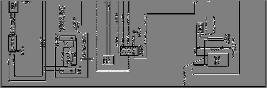

30 Electrical Schematic 30
31 Appendix A SERVICE BULLETIN 0074 NCC Electronic Temperature Control GOLD MEDAL PRODUCTS COMPANY Medallion Drive Phone: (513) Cincinnati, Ohio Fax: (513) U.S.A. SERVICE BULLETIN 0074 Date Issued 8/23/04 revised 12/15/04 Model(s) Affected- All Poppers with NCC Electronic Temperature Control This bulletin describes popcorn machines equipped with an Electronic Temperature Control manufactured by NCC for Gold Medal Products. There are no mechanical thermostats used with this control. The mechanical thermostats are replaced by two Thermocouple Sensors, one for the High Limit and one for Temperature Control. This model is also equipped with a beeper and an indicator light that activate when the kettle heat switch is on and the kettle is at or over the dump temperature set point. Note: All components listed in this service bulletin are shown in Figure 1 on page 5. Operation The control is factory set to a temperature which stops power to the kettle when the thermocouple in the kettle reaches the set temperature. See Table 1 for a list of temperature jumper settings. There is a Kettle Dump Potentiometer that is used to set the Alarm point for loading and dumping the kettle. This potentiometer will subtract up 10% of the set point jumper value to fine tune the alarm point. If the kettle heat switch is turned on and the beeper is sounding one of the following actions should be taken: 4. Load the corn and oil or 5. Dump the popped corn from the kettle or 6. Turn off the kettle heat switch if you are finished popping corn. The High Limit Control is fixed at 550ºF and cannot be adjusted. Overshoot Potentiometer For a stainless steel kettle the Patented First Time Overshoot Circuit Potentiometer is set to - 20%, full clockwise (CW). DO NOT change this setting. This setting prevents the kettle from getting too hot during the first time heat up. When power is applied to the kettle and the kettle temperature is below the first time overshoot temperature set point the power to the kettle will be turned off at the overshoot temperature. The alarm will NOT sound. The kettle will then cool to a point below the first time overshoot value and start to reheat. When the kettle reaches the alarm temperature the alarm will sound and it is time to load the kettle with corn and oil. The kettle will now operate from the alarm and jumper set points. The first time overshoot set point is based on the power set point jumper setting. For example if the power set point jumper is set at 460ºF 31
32 Appendix A SERVICE BULLETIN 0074 NCC Electronic Temperature Control the first time overshoot set point will be 368ºF (460ºF-92ºF). The 92ºF is 20% of the 460ºF value. Adjustment of Alarm Set Point If you would like to have the beeper sound sooner or later than the factory setting, adjust the temperature setting as follows: 1. To sound the beeper sooner, turn the Kettle Dump pot clockwise (CW) towards the -10% mark on the control board. This will lower the alarm set point without changing the power set point jumper value. For example if Set Point jumper is set at 400ºF and the Kettle Dump pot is at -5% the kettle alarm temperature will be 380 ºF (400ºF - 20ºF), the power set point stays at 400ºF. If the pot is set at 0% the alarm and power set points are the same, 400ºF. If the pot is set at -10% the alarm set point is 360ºF (400ºF -40ºF) and the power set point is 400ºF. A change of 1% CW on the potentiometer will subtract about 3 seconds from the alarm set point. 2. To sound the beeper later, turn the Kettle Dump pot counterclockwise (CCW). A change of 1% CCW on the Dump potentiometer will add about 3 seconds to the alarm set point. Adjustment of beeper Sound Level If you would like to lower the beeper volume, remove jumper J3 shown in figure 1. To stop the beeper remove jumper J4. Salt / Sweet Option The control board will have two separate set point jumpers. The lower value jumper is the sweet temperature. These jumpers have wires attached to them going directly to a salt/sweet switch or a salt /sweet relay. The salt/sweet switch selects which jumper is active. Factory Set Point Jumper Settings Model Temperature Salt F Temperature Sweet F Macho Pop/Pappy s % 2102E Citation % 52 oz. Medallion % 32 Oz. Pop-O-Gold % 2010 Astro Pop % 28 oz. Cornado 440/ % 36 oz. Cornado 440/ % 48 oz. Cornado 440/ % Table 1 Overshoot Potentiometer 32
33 Appendix A Trouble Shooting for Service Personnel SERVICE BULLETIN 0074 NCC Electronic Temperature Control 1. If the kettle does not heat and there are no beeper sounds, look on the heat control to see if the green PWR LED is on. The PWR LED indicates there is power to the control board. If the LED is not on, check the Heat Switch and wiring. Check for 120 VAC (230 VAC) across terminals L1 & L2. 2. If the kettle does not heat and/or the beeper sounds continuously check to be sure there is a set point jumper in one of the 6 locations. Remove the jumper and clean the pins off, sometimes the conformal coatings gets on the pins and acts as an insulator. 3. If the kettle does not heat and/or the beeper sounds continuously, look on the heat control to see if the red Probe LED is on. The Probe LED indicates there is a thermocouple problem. a. If the Probe LED is on and the Limit & Heat LED s are off and the beeper is on there is a problem with the Heat Thermocouple, TC-B wiring. Look at the terminal blocks for a loose connection. Check the kettle wiring for a loose or broken thermocouple wire. b. If the Probe and Heat LED s are on and the beeper is off there is a problem with the Limit thermocouple, TC-A wiring. Look at the terminal blocks for a loose connection. Check the kettle wiring for a loose or broken thermocouple wire. c. If the Probe LED is not on the thermocouple connections are OK. If the Limit LED and Alarm LED s are on and the beeper is on check the Set Point Jumpers. Most likely the jumper has come off. If the Jumper is in place temporarily move it to a different temperature setting to see if the control then works. 4. If the kettle heats for a very short time and then stops. a. If the Probe, Heat and Alarm LED s are on and the beeper is on the Heat Thermocouple, TC-B is wired reverse. Check for reversed thermocouple leads, see note 2 below. If the thermocouple leads are reversed the kettle will heat up to about 130 F and stop with the Probe LED on. The leads could be reversed at either the heat control itself or the terminal block. b. If the Probe and Heat LED s are on and the beeper is off the Limit Thermocouple, TC-A is wired reverse, troubleshoot as in item 3-a above. Note this is similar to 2-b above, the difference is the kettle started to heat and then quit. 5. The kettle is popping normally but the beeper does not sound, check for a missing jumper at J4. 5. Salt or Sweet temperature is not working correctly. Check to make sure both temperature set point jumpers are in place and wired correctly. Be sure the common wire for the switch or relay is connected to a bottom pin of one of the set point jumpers. 33
34 Appendix A SERVICE BULLETIN 0074 NCC Electronic Temperature Control Notes: 1. Do not adjust the (4) painted potentiometers numbers R89, R36, R73 and R74 on the electronic heat control. If adjusted, the performance will be erratic and could result in an over temperature condition. 2. Thermocouple wire consists of (2) different wires made of different materials that are color-coded polarity. It is important that red (-) is connected to red (-), and yellow (+) is connected to yellow (+), at the lead-in plug, the receptacle, and at the electronic heat control. Note that the red lead is magnetic if you have trouble determining which is which. 3. This control includes a patented first time overshoot circuit. On power up if the kettle is below the first time overshoot temperature it is normal for the heat light to go off and the kettle to stop heating before the set dump temperature. The kettle will continue to heat as soon as the kettle temperature drops below the first time overshoot temperature. 4. The Limit, Heat and Alarm LED s indicate the state of the output relays of the temperature control board. If an output LED is lit there should be 120 VAC on the respective ¼ faston with respect to common. The main voltage to the temperature control must be wired such that the hot 120 VAC (230 VAC) is connected to L1. The L2 connection is for the neutral or common voltage wire. If you have any questions, please feel free to call Technical Service or Engineering at Gold Medal Products Co. Toll Free Phone Number
35 Appendix A TC-B is the Control Thermocouple Input. + is Yellow Wire. SERVICE BULLETIN 0074 NCC Electronic Temperature Control TC-A is the Limit Thermocouple Input. + is Yellow Wire. Beeper Off/On Jumper. Remove for no Sound. Beeper Volume Jumper. Remove For lower Sound. Set Point Jumper. See Table 1 for Location. Salt/Sweet there are two jumpers with wires. The common wire is connected to a bottom jumper pin. First Time Overshoot Pot. Factory Set. DO NOT ADJUST! Kettle Dump Pot. Minus 0-10%. Turning CW will signal sooner, CCW will signal later. FIGURE 1 L2 is neutral wire. L1 is hot wire. Alarm Light Output Limit Contactor or relay Output. Heat Contactor or Relay Output. Limit, Heat & Alarm LEDS. Power On LED. 35 Probe Fault LED. Jumper A&B for 120 VAC. Jumper C only for 230 VAC.
36 WARRANTY WE WARRANT to the original purchaser the Gold Medal equipment sold by us to be free from defects in material or workmanship under normal use and service. Our obligation under this warranty shall be limited to the repair or replacement of any defective part for a period of six (6) months from the date of sale to the Original Purchaser with regard to labor and two (2) years with regard to parts and does not cover damage to the equipment caused by accident, alteration, improper use, voltage, abuse, or failure to follow instructions. THIS WARRANTY IS IN LIEU OF ALL OTHER WARRANTIES EXPRESSED OR IMPLIED, AND OF ALL OTHER OBLIGATIONS OR LIABILITIES ON OUR PART, INCLUDING THE IMPLIED WARRANTY OF MERCHANTIBILITY. THERE ARE NO WARRANTIES WHICH EXTEND BEYOND THE DESCRIPTION ON THE FACE HEREOF. We neither assume, nor authorize any other person to assume for us, any other obligation or liability in connection with the sale of said GOLD MEDAL equipment or any part thereof. The term Original Purchaser as used in this warranty shall be deemed to mean that person, firm, association, or corporation who was billed by the GOLD MEDAL PRODUCTS COMPANY, or their authorized distributor for the equipment. THIS WARRANTY HAS NO EFFECT AND IS VOID UNLESS THE ORIGINAL PURCHASER FIRST CALLS GOLD MEDAL PRODUCTS COMPANY AT TO DISCUSS WITH OUR SERVICE REPRESENTATIVE THE EQUIPMENT PROBLEM, AND, IF NECESSARY, FOR INSTRUCTIONS CONCERNING THE REPAIR OR REPLACEMENT OF PARTS. NOTE: This equipment is manufactured and sold for commercial use only. GOLD MEDAL PRODUCTS COMPANY Medallion Drive Cincinnati, Ohio USA Phone: Fax: The text, descriptions, graphics and other material in this publication are the proprietary and exclusive property of Gold Medal Products Company and shall not be used, copied, reproduced, reprinted or published in any fashion, including website display, without its express written consent. 36
Pop-O-Gold 32oz. Popcorn Machine Instruction Manual For Domestic Models Manufactured after December 2004
 Part No. 41490 Revised: November 2007 Pop-O-Gold 32oz. Popcorn Machine Instruction Manual For Domestic Models Manufactured after December 2004 Cincinnati, OH 45241-4807 USA Table of Contents I. Safety
GRAND POP-O-GOLD 32oz. Instruction Manual Models #2848, #2860, #2872, #2861, #2873 Domestic Models Only
 Part No. 48791 Revised: September 2009 GRAND POP-O-GOLD 32oz. Instruction Manual Models #2848, #2860, #2872, #2861, #2873 Domestic Models Only Cincinnati, OH 45241-4807 USA SAFETY PRECAUTIONS 2 INSTALLATION
Astro-Pop 20oz. Popcorn Machine Export Instruction Manual 2010XE
 Part No. 41488EX Revised: July 2009 Astro-Pop 20oz. Popcorn Machine Export Instruction Manual 2010XE Cincinnati, OH 45241-4807 USA 1 SAFETY PRECAUTIONS 2 INSTALLATION INSTRUCTIONS CHECKING SHIPMENT Unpack
SAM S CLUB POPPER UniMaxx Kettle Popcorn Machine Instruction Manual Model #2085CL
 SAM S CLUB POPPER UniMaxx Kettle Popcorn Machine Instruction Manual Model #2085CL Part No. 49388 Revised: March 2009 Cincinnati, OH 45241-4807 USA SAFETY PRECAUTIONS 2 Model #2085CL UniMaxx INSTALLATION
 WARNING!! The attached Gold Medal Manual is for reference only and is not intended for any other purpose. The information contained in these on line manuals is subject to change at any time. Improvements
Export Bucket Pump Instruction Manual Models: 2114XE & 2114XD
 Part No. 79064XE Revised: August 2006 Export Bucket Pump Instruction Manual Cincinnati, OH 45241 USA SAFETY PRECAUTIONS INTRODUCTION This manual provides instruction for installation and operation of the
Countertop B.I.B. Butter Dispenser Instruction Manual Model #2496
 Part No. 39177 Countertop B.I.B. Butter Dispenser Instruction Manual Cincinnati, OH 45241-4807 USA SAFETY PRECAUTIONS Installation Instructions Countertop B.I.B. Checking Shipment Unpack all cartons and
Cincinnati, OH USA
 Astro Pop Warmer Instruction Manual Model #2002 Part No. 61987 Revised July 2000 Cincinnati, OH 45241-4807 USA e-mail: goldme19@eos.net www.gmpopcorn.com SAFETY PRECAUTIONS INTRODUCTION Your new #2002
Gay 90 s Whiz Bang. Instruction Manual Model #2014. Cincinnati, OH USA. Part No Revised June 1996
 Gay 90 s Whiz Bang Instruction Manual Model #2014 Part No. 47700 Revised June 1996 Cincinnati, OH 45241-4807 USA SAFETY PRECAUTIONS INSTALLATION Your new Antique Popcorn Machine is completely assembled.
!"" #$% "!&' ( ( ) *
 *") !"" #$% "!&' (( ) * FunPop CART Assembly Manual Model # 2689 CARTS Part No. 59411 Revised: FEB 2009 Cincinnati, OH 45241-4807 USA INSTALLATION INSTRUCTIONS Checking Shipment Unpack all cartons and check
!"" #$% "!&' (( ) * FunPop CART Assembly Manual Model # 2689 CARTS Part No. 59411 Revised: FEB 2009 Cincinnati, OH 45241-4807 USA INSTALLATION INSTRUCTIONS Checking Shipment Unpack all cartons and check
Bag-In-A-Box Oil Pump System
 Bag-In-A-Box Oil Pump System Part No. 79285 Revised February 2000 INSTRUCTION MANUAL MODEL #2257 AND MODEL #2257H Cincinnati, OH 45241-4807 USA e-mail: goldme19@eos.net www.gmpopcorn.com SAFETY PRECAUTIONS
Accu-Meter Oil Pump. Instruction Manual. Model #2114. Cincinnati, OH USA. Part No Revised June 1996
 Instruction Manual Model #2114 Part No. 79064 Revised June 1996 Cincinnati, OH 45241-4807 USA SAFETY PRECAUTIONS INSTALLATION CHECKING SHIPMENT Your new Accu-Meter Oil Pump is completely assembled and
Hot Dog Roller Grills Instruction Manual Model #8023, Model #8024 and Model #8025 Model #8023SL, Model #8024SL and Model #8025SL
 Part No. 87630 Revised November 2007 Hot Dog Roller Grills Instruction Manual Model #8023, Model #8024 and Model #8025 Model #8023SL, Model #8024SL and Model #8025SL Model #8023 shown Cincinnati, OH 45241-4807
Automatic Butter Dispenser Instruction Manual Model #2395NS
 Automatic Butter Dispenser Instruction Manual Part No. 39642 Revised: July 2006 Cincinnati, OH 45241 USA Safety Precautions Automatic Butter Dispenser 2 INTRODUCTION Automatic Butter Dispenser This manual
Cincinnati, OH USA
 Part No. 87630PE Revised November 2007 Hot Dog Roller Grills Non-Stick Instruction Manual Model #8023PE, Model #8024PE and Model #8025PE Model #8023SLPE, Model #8024SLPE and Model #8025SLPE Model #8023PE
Part No DROP IN POPCORN WARMERS Instruction Manual Model #2343, 2344, 2345
 Part No. 39406 DROP IN POPCORN WARMERS Instruction Manual Model #2343, 2344, 2345 SAFETY PRECAUTIONS 2 INSTALLATION INSTRUCTIONS Inspection of Shipment: Unpack all cartons and check thoroughly for any
!"" #$% "!&' ( ( ) *
 *") !"" #$% "!&' (( ) * FunPop Assembly Manual Model # 2649CR Part No. 59406CR Revised: October 2004 Cincinnati, OH 45241-4807 USA INSTALLATION INSTRUCTIONS Checking Shipment Unpack carton and check thoroughly
!"" #$% "!&' (( ) * FunPop Assembly Manual Model # 2649CR Part No. 59406CR Revised: October 2004 Cincinnati, OH 45241-4807 USA INSTALLATION INSTRUCTIONS Checking Shipment Unpack carton and check thoroughly
FUNNEL CAKE FRYER Instruction Manual Models: 8078 / FC-4, 8082 / FC-6, and 8090 / FC-4
 Part No. 89784 Revised: December 2005 FUNNEL CAKE FRYER Instruction Manual Models: 8078 / FC-4, 8082 / FC-6, and 8090 / FC-4 Cincinnati, OH 45241-4807 USA GAS SAFETY PRECAUTIONS INSTALLATION INSTRUCTIONS
Instruction Manual. Fudge Puppy Display Case
 Instruction Manual Fudge Puppy Display Case Model No. 5535 10700 Medallion Drive, Cincinnati, Ohio 45241-4807 USA 2014 Gold Medal Products Co. Part No. 89074 SAFETY PRECAUTIONS DANGER Machine must be properly
Color Wheel Instruction Manual Model #7767
 Part No. 52179 Revised: April 2004 Color Wheel Instruction Manual Model #7767 Cincinnati, OH 45241-4807 USA SAFETY PRECAUTIONS INSTALLATION INSTRUCTIONS CHECKING SHIPMENT The Color Wheel is shipped in
PEANUT ROASTER Instruction Manual Model #5081
 Part No. 46355 Revised: September 2004 Instruction Manual Model #5081 Cincinnati, OH 45241-4807 USA SAFETY PRECAUTIONS 2 MODEL # 5081 OPERATING INSTRUCTIONS Unpacking and Assembly After unpacking your,
PLINKO Instruction Manual Model #7760
 Part No. 52148 Revised November 2002 Instruction Manual Model #7760 Cincinnati, OH 45241-4807 USA SAFETY SHEET 2 INSTALLATION INSTRUCTIONS CHECKING SHIPMENT The is shipped in two corrugated cartons. One
ROLLER GRILL Instruction Manual Model #8223, 8224, Part No Revised:March 2008
 ROLLER GRILL Instruction Manual Model #8223, 8224, 8225 Part No. 88189 Revised:March 2008 Safety Precautions Models #8223, 2 #8224, #8225 FORWARD This manual covers the model # 8223, # 8223, 8225 ROLLER
AUTO-BREEZE Cotton Candy Machine Instruction Manual Model #3052
 Part No. 55147 Revised: August 2004 AUTO-BREEZE Cotton Candy Machine Instruction Manual Cincinnati, OH 45241-4807 USA Safety Precautions Auto-Breeze 2 INTRODUCTION Your Floss Machine warranty is described
Film-Tech. The information contained in this Adobe Acrobat pdf file is provided at your own risk and good judgment.
 Film-Tech The information contained in this Adobe Acrobat pdf file is provided at your own risk and good judgment. These manuals are designed to facilitate the exchange of information related to cinema
Sno Konette. Instruction Manual Deluxe Model #1002EX Standard Model #1003EX DC Battery Model #1009EX. Cincinnati, OH USA.
 Sno Konette Instruction Manual Deluxe Model #1002EX Standard Model #1003EX DC Battery Model #1009EX Part No. 22045EX Revised June 1996 Model #1002EX Model #1003EX Cincinnati, OH 45241-4807 USA SAFETY PRECAUTIONS
Super Floss Instruction Manual Model #3038 and 3038EX
 Part No. 88761 Revised Aug 2003 Super Floss Instruction Manual Cincinnati, OH 45241-4807 USA Safety Precautions 2 INTRODUCTION Your Floss Machine warranty is described on the back page of this manual.
Giant Cone Display Case
 Instruction Manual Model #8211 Part No. 76132 Revised June 1996 Cincinnati, OH 45241-4807 USA SAFETY PRECAUTIONS This equipment is designed and sold for commercial use only. This equipment is not to be
Dispenser & Warmer RIC-1909 RIC-1909EXP
 Dispenser & Warmer RIC-1909 RIC-1909EXP Safety Precautions CAUTION This equipment is designed and sold for commercial use only. This equipment is not to be used by the consumer in home use. Do not allow
DIGITAL GIANT POPCORN MACHINE SERVICE MANUAL
 3243 North California Avenue, Chicago, IL 60618 DIGITAL GIANT POPCORN MACHINE SERVICE MANUAL Included in this manual: *One Pop Option *Salt/Sugar Option 120/208 Volt, Single and Three Phase, 60 Hz 120/240
Part No Revised May 2002
 Part No. 42231 Revised May 2002 Electronic Tornado Deluxe Whirlwind X15 Instruction Manual Model #3015A, #3015AX, #3005E, 3005XE, #3008E, #3008XE, #3007E, #3007XE, #3009E, and #3009XE Cincinnati, OH 45241-4807
Reproduction or other use of this Manual, without the express written consent of Vulcan, is prohibited.
 SERVICE MANUAL ELECTRIC BRAISING PANS (30 & 40 GALLON) VE30 VE40 ML-126849 ML-126850 VE40 SHOWN - NOTICE - This Manual is prepared for the use of trained Vulcan Service Technicians and should not be used
Blue Air. Commercial Refrigeration Inc. Installation & Operation Manual Chef Bases
 Blue Air Commercial Refrigeration Inc. Installation & Operation Manual Chef Bases Please read this manual completely before installing or operating this unit! BACB53 BACB71 BACB74 BACB83 BACB86 BACB96
Blue Air. Commercial Refrigeration Inc. Installation & Operation Manual Glass Door Countertop Refrigerator
 Blue Air Commercial Refrigeration Inc. Installation & Operation Manual Glass Door Countertop Refrigerator Please read this manual completely before installing or operating this unit! BAGR7 Blue Air reserves
STAR-MAX ELECTRIC HOT PLATE MODELS 502 AND 502F
 Star Manufacturing International Inc. 10 Sunnen Drive St. Louis, MO 63143 Phone: (314) 781-2777 FAX: (314) 781-3636 Installation and Operating Instructions 2M-Y7466 Rev. B 7/18/95 STAR-MAX ELECTRIC HOT
Installation & Operation Manual Chef Base
 Installation & Operation Manual Chef Base Please read this manual completely before installing or operating this unit! BACB53 BACB53M BACB71 BACB71M BACB74 BACB74M BACB83 BACB83M BACB86 BACB86M BACB96
TO ORDER PARTS CALL: (479) or
 or") Owner s Manual Industrial Ergonomic User-Friendly Hand Controls Date Manufactured: / / o Mart Cart XTi 24 Model 03522 - SKU# 280-3522 o Mart Cart XTi 24 Model 03524 - SKU# 280-3524 CONGRATULATIONS You
Owner s Manual Industrial Ergonomic User-Friendly Hand Controls Date Manufactured: / / o Mart Cart XTi 24 Model 03522 - SKU# 280-3522 o Mart Cart XTi 24 Model 03524 - SKU# 280-3524 CONGRATULATIONS You
Automated I.V. Stand Cat. No OPERATOR S MANUAL. Operation& Maintenance Instructions. Raising the Standard of Care!
 Automated I.V. Stand Cat. No. 741314 OPERATOR S MANUAL Operation& Maintenance Instructions Raising the Standard of Care! Table of Contents Warranty....................... 2 Hardware.......................
OPERATING MANUAL. aeration fans. models: sa sa sa SAFETY PRACTICES
 2237 MARSHALLTOWN BLVD. MARSHALLTOWN, IOWA 50158 PHONE: (641) 753-5601 TOLL FREE: 1-800-383-5601 FAX: (641) 752-9748 WWW.SPREAD-ALLMFG.NET OPERATING MANUAL aeration fans models: sa-12075 sa-12100 - sa-14100
Reach ins, Freeezers & Refrigerators Installation & Operation Manual
 Reach ins, Freeezers & Refrigerators Installation & Operation Manual BSR23 BSF23 BSR49 BSF49 BSR72 BSF72 IMPORTANT SAFETY INSTRUCTIONS (SAVE THESE INSTRUCTIONS) Visit us on the web at www.blueairinc.com
STAR-MAX ELECTRIC HOT PLATE
 Star Manufacturing International Inc. 10 Sunnen Drive St. Louis, MO 63143 Phone: (314) 781-2777 Fax: (314) 781-3636 Installation and Operating Instructions 2M-Z1436 Rev. C 1/8/03 STAR-MAX ELECTRIC HOT
ULTRAWARMER HOLDING STATION INSTALLATION & OPERATIONS MANUAL
 ULTRAWARMER HOLDING STATION INSTALLATION & OPERATIONS MANUAL This document includes: Warranty Specifications Wiring Diagram Operating Instructions Cleaning Instructions Parts List P/N: 11B741 Model UW1
CSA CERTIFIED Conforms to UL 507
 Installation tion Instructions Please read and save these instructions! TURBO/MAXX12 Volt All Weather RV Ventilator Fans P/N 00-965001 Deluxe Model 1200T WITH THERMOSTAT P/N 00-965007 Standard Model 3550
Instruction Manual. Whirlwind SHO
 Instruction Manual Whirlwind SHO Model No. 3009 10700 Medallion Drive, Cincinnati, Ohio 45241-4807 USA Part No. 63898 SAFETY PRECAUTIONS Page 2 INSTALLATION INSTRUCTIONS Inspection of Shipment After unpacking,
LARGE CAPACITY INCUBATOR Installation, Operation and Maintenance Instructions
 LARGE CAPACITY INCUBATOR Installation, Operation and Maintenance Instructions GENERAL 2 Inspection 2 Location 2 INSTALLATION 2 Door Alignment 2 Shelf Installation 2 Remote Contacts 2 2-10 Volt DC Output
MODEL MA4210 Installation and Operation Manual Important:
 MODEL MA4210 Installation and Operation Manual Important: This manual contains specific cautionary statements relative to worker safety. Read this manual thoroughly and follow as directed. It is impossible
OPERATING MANUAL. centrifugal fan SAFETY PRACTICES
 2237 MARSHALLTOWN BLVD. MARSHALLTOWN, IOWA 50158 PHONE: (641) 753-5601 TOLL FREE: 1-800-383-5601 FAX: (641) 752-9748 WWW.SPREAD-ALLMFG.NET OPERATING MANUAL centrifugal fan SAFETY PRACTICES 1. Have a qualified
The Da-Lite Difference.
 The Da-Lite Difference. Instruction Book for Boardroom Electrol DA-LITE SCREEN COMPANY, INC. 3100 North Detroit Street Post Office Box 137 Warsaw, Indiana 46581-0137 Phone: 574-267-8101 800-622-3737 Fax:
Operator's Manual. Storage System. Ultrasound Probe Cabinet. Manufactured by:
 Storage System Ultrasound Probe Cabinet Operator's Manual Manufactured by: CIVCO Medical Solutions 102 First Street South Kalona, IA 52247 USA 319.248.6757 / 800.445.6741 WWW.CIVCO.COM Copyright 2018 All
Safety, Installation and Service Manual Models 1952, 1953 & 1972
 Ultraviolet Germicidal Lamps Model 1952 24 Rooftop Unit Model 1953 32 Rooftop Unit Model 1972 Rooftop Unit, Internal Mount Safety, Installation and Service Manual Models 1952, 1953 & 1972 READ AND SAVE
INSTRUCTIONS FOR THE RELIANCE CONTROLS ARM SERIES AUTOMATIC TRANSFER SWITCH
 INSTRUCTIONS FOR THE RELIANCE CONTROLS ARM SERIES AUTOMATIC TRANSFER SWITCH THE RELIANCE CONTROLS ARM SERIES AUTOMATIC TRANSFER SWITCH IS NOT FOR "DO-IT-YOURSELF" INSTALLATION. It must be installed by
Air Curtain. Installation, Operating and Maintenance Instructions
 Installation, Operating and Maintenance Instructions Save this manual for future reference. Air Curtain Model Numbers: ES026, ES036, ES042, ES048, ES060, ES072 READ THIS OWNER S MANUAL CAREFULLY BEFORE
A48 / A48B (base plate) BATTERY CHARGER
 BATTERY CHARGER") A48 / A48B (base plate) BATTERY CHARGER CPN41054 ISSUE DATE: 12315-8/98 ECN/DATE 106 BRADROCK DRIVE DES PLAINES, IL. 60018-1967 (847) 299-1188 FAX: (847)299-3061 15349-07-07/02 16041 6/03 14575-2/01 INSTRUCTION
A48 / A48B (base plate) BATTERY CHARGER CPN41054 ISSUE DATE: 12315-8/98 ECN/DATE 106 BRADROCK DRIVE DES PLAINES, IL. 60018-1967 (847) 299-1188 FAX: (847)299-3061 15349-07-07/02 16041 6/03 14575-2/01 INSTRUCTION
Adjustable Angled Incline Conveyor Owners Manual with Operating Instructions
 Adjustable Angled Incline Conveyor Owners Manual with Operating Instructions Revision 012211 Table of Contents Basic Conveyor Features 3 Getting Started 4 Setting Up the Incline Conveyor 5 Belt Removal
1250 LB. CAPACITY MECHANICAL WHEEL DOLLY
 1250 LB. CAPACITY MECHANICAL WHEEL DOLLY 67287 SET-UP AND OPERATING INSTRUCTIONS Visit our website at: http://www.harborfreight.com Read this material before using this product. Failure to do so can result
Installation, Operating & Maintenance Instructions
 Electromechanical Linear Actuators Installation, Operating & Maintenance Instructions with parts list TAC Models with Clutch TAL Models with Limit Switches TAC Models with Limit Switches and Potentiometer
The Da-Lite Difference.
 The Da-Lite Difference. Instruction Book for Large Advantage Electrol DA-LITE SCREEN COMPANY, INC. 3100 North Detroit Street Post Office Box 137 Warsaw, Indiana 46581-0137 Phone: 574-267-8101 800-622-3737
READ AND FOLLOW ALL SAFETY INSTRUCTIONS SAVE THESE INSTRUCTIONS
 7.5 Swift Lock Ready Shape Tree (Patent Pending) Instructions IMPORTANT SAFETY INSTRUCTIONS When using electrical products, basic precautions should always be followed including the following: READ AND
PowerFlo 20 Parts List/Assembly Instructions/Users Guide ***PLEASE READ ALL INSTRUCTIONS CAREFULLY AND THOROUGHLY***
 PowerFlo 20 Parts List/Assembly Instructions/Users Guide ***PLEASE READ ALL INSTRUCTIONS CAREFULLY AND THOROUGHLY*** Owners Manual (Please check to make sure to locate all parts before assembly.) 11/12/2008
PARTS & SERVICE Manual for PANORAMA ROTISSERIE Model SP-7
 PARTS & SERVICE Manual for PANORAMA ROTISSERIE Model SP-7 THIS MANUAL SHOULD BE RETAINED FOR FUTURE USE SP7serv 12-22-08 WARRANTY The SP-7 carries a 1 year warranty on parts and labor from date of unit
H-2034, H-2035 SHRINK TUNNEL
 H-2034, H-2035 SHRINK TUNNEL SPECIFICATIONS IMPORTANT! Read this manual thoroughly and familiarize yourself with ALL controls and operating features. Keep this manual for future reference and maintenance.
Cambro Camtherm OWNER S MANUAL. Plate Heater.
 OWNER S MANUAL Cambro Camtherm Plate Heater This manual covers instructions for the following models: CHPL100 Cambro Camtherm Plate Heater Table of Contents Introduction... 1 Section I Product Information...
Electric Griddle. Owner s Manual. Models TMGE24, TMGE36, TMGE48
 Electric Griddle Owner s Manual Models, TMGE36, TMGE48 This manual includes material related to installation, use, cleaning, and care. Exploded view[s], as well as any available parts list[s] and wiring
Heavy Duty Four Wheeled Walker
 Heavy Duty Four Wheeled Walker Weight Capacity: 500 lbs. ITEM # W1802 Made in China 2011 ESSENTIAL MEDICAL SUPPLY, INC. Manufactured for Orlando, FL 32822 -- SAVE THESE INSTRUCTIONS -- Do not attempt to
The Da-Lite Difference.
 The Da-Lite Difference. Instruction Book for Cosmopolitan Electrol For Sizes Up To 9'x12' DA-LITE SCREEN COMPANY, INC. 3100 North Detroit Street Post Office Box 137 Warsaw, Indiana 46581-0137 Phone: 574-267-8101
Read this entire manual before operation begins.
 Read this entire manual before operation begins. Record below the following information which is located on the serial number data plate. Serial No. Model No. Date of Installation Contents Specifications.............
MODEL SCA Installation and Operation Manual Important:
 MODEL SCA Installation and Operation Manual Important: This manual contains specific cautionary statements relative to worker safety. Read this manual thoroughly and follow as directed. It is impossible
CRD610 Automatic Fitting Inserter
 CRD610 Automatic Fitting Inserter OPERATIONS MANUAL VERSION 1.2 LAST EDITED 12.12.2018 cleanroomdevices.com 1 Table of Contents Title Page. 1 Table of Contents...2 1.0 General Product & Safety Information....3
STOP. 44" High Speed Sweeper. Operator's Manual. Model No Safety Assembly Operation Maintenance Parts
 Operator's Manual STOP 44" High Speed Sweeper Model No. 486.029 DO NOT RETURN TO STORE For Missing Parts or Assembly Questions Call 1-866-576-8388 CAUTION: Before using this product, read this manual and
SPC-PANEL Simplex, Single Phase Pump Control Panel
 Pump Installation and Service Manual SPC-PANEL Simplex, Single Phase Pump Control Panel Pump Controls for 2 HP Grinder Pumps NOTE! To the installer: Please make sure you provide this manual to the owner
OWNER S MANUAL CAMBRO CAMDUCTION COMPLETE HEAT CHARGER.
 OWNER S MANUAL This owner s manual applies to all of the following product models: Model MDSCDCP9 (Special Order Only) For use with CAMBRO Camduction Pellet MDSCDP9 Note: Pellet Requires Underliner MDSCDL9
READ AND FOLLOW ALL SAFETY INSTRUCTIONS SAVE THESE INSTRUCTIONS
 5 Swift Lock Ready Shape Tree (Patent Pending) Instructions IMPORTANT SAFETY INSTRUCTIONS When using electrical products, basic precautions should always be followed including the following: READ AND FOLLOW
IV STANDS. Assembly, Usage and Maintenance INSTRUCTION MANUAL
 INSTRUCTION MANUAL IV STANDS Assembly, Usage and Maintenance Read and understand all of the instructions and safety information in this manual before operating this product. MAN-045 REV A 2018 MAC Medical,
MP/MTFL LIGHT FIXTURE (Dimming)
") Robern 701 N. Wilson Ave. Bristol, PA 19007 800.877.2376 MP/MTFL LIGHT FIXTURE (Dimming) General Notes 1. It is important that the armored cable be installed during electrical rough in. 2. When surface
Robern 701 N. Wilson Ave. Bristol, PA 19007 800.877.2376 MP/MTFL LIGHT FIXTURE (Dimming) General Notes 1. It is important that the armored cable be installed during electrical rough in. 2. When surface
SUBMERSIBLE MINI-PUMP
 SUBMERSIBLE MINI-PUMP Model 41287 Set up And Operating Instructions Diagrams within this manual may not be drawn proportionally. Due to continuing improvements, actual product may differ slightly from
4" ENVIRONMENTAL E-SERIES PUMPS OWNER'S MANUAL. DANGER warns about hazards that will cause. WARNING warns about hazards that can cause
 4" ENVIRONMENTAL E-SERIES PUMPS OWNER'S MANUAL BEFORE INSTALLING PUMP, BE SURE TO READ THIS OWNER S MANUAL CAREFULLY. CAUTION Fill pump with water before starting or pump will be damaged. The motor on
215E. Operator and Parts Manual MM158
 5E Operator and Parts Manual MM58 This manual is furnished with each new TENNANT Model 5E This manual consists of Specifications; Operation; Maintenance; Appendix; the How To Use This Manual; Low Dump
Instruction Manual AVTM for. Strip Chart Recorder Catalog Nos and
 AVTM220003 Rev. B January 2003 Instruction Manual AVTM220003 for DC µa Strip Chart Recorder Catalog Nos. 220003 and 220003-47 PO Box 9007 Valley Forge, PA 19485-1007 U.S.A. 610-676-8500 Shipping Address:
TRINETICS CSD SERIES OIL SWITCH INSTALLATION INSTRUCTIONS
 TRINETICS CSD SERIES OIL SWITCH INSTALLATION INSTRUCTIONS 33220900 DECEMBER 2011 Caution: The equipment covered by these installation instructions should be installed and serviced only by properly trained
UV DISINFECTION UNIT MODEL 3G
 SALCOR INC. P. O. Box 1090 Fallbrook, CA 92088-1090 Telephone: (760) 731-0745 Fax: (760) 731-2405 INSTALLATION MANUAL UV DISINFECTION UNIT MODEL 3G February, 2011 I. INSTALLATION INSTRUCTIONS WARNING!
Read this entire manual before operation begins.
 Read this entire manual before operation begins. Record below the following information which is located on the serial number data plate. Serial No. Model No. Date of Installation Contents Specifications.............
RESOURCE GUIDE. P r o d u c t M a n u a l. START International
 RESOURCE GUIDE P r o d u c t M a n u a l The information contained in this Resource Guide along with additional maintenance and repair information, videos and photos can be found online at www.startinternational.com
Linear Actuator. Installation Manual. warranty installation parts list. Linear Actuator Installation Manual Page 1
 Linear Actuator Installation Manual warranty installation parts list January 2004 Linear Actuator Installation Manual Page 1 MA1221B12 Warranty Information Chore-Time Equipment ( Chore-Time ) warrants
MODEL A96 SERIES. 130Vdc Switchmode Utility Rectifier / Battery Charger. Used with LaMarche Power Cage ECN/DATE
 MODEL A96 SERIES 130Vdc Switchmode Utility Rectifier / Battery Charger Used with LaMarche Power Cage CPN112138 ECN/DATE ISSUE DATE: ECN 17010-12/05 106 BRADROCK DRIVE DES PLAINES, IL. 60018-1967 (847)
Henny Penny Hand Breader/Sifter Model HB-11
 Henny Penny Hand Breader/Sifter Model HB-11 TECHNICAL MANUAL TABLE OF CONTENTS Section Page Section 1. MAINTENANCE... 1-1 1-1. Introduction....1-1 1-2. Safety... 1-1 1-3. Replacement of Belt...1-2 1-4.
OIL! Use #30 SAE Motor Oil in the gear case. 1. Use the bottle of oil that is included.
 2237 MARSHALLTOWN BLVD. MARSHALLTOWN, IOWA 50158 PHONE: (641) 753-5601 TOLL FREE: 1-800-383-5601 FAX: (641) 752-9748 WWW.SPREAD-ALLMFG.NET Instructions models: e-2, e-3, & e-6 grain spreaders ASSEMBLY
Heated Bakery Merchandiser Series. Series: WBC Operation Manual
 Heated Bakery Merchandiser Series Series: WBC Operation Manual WHAT IS COVERED WHO IS COVERED COVERAGE PERIOD WARRANTY COVERAGE EXCEPTIONS EXCLUSIONS INSTALLATION BKI LIMITED WARRANTY 2812 Grandview Drive
Tissue Master. User Manual
 Tissue Master User Manual This page left blank intentionally This manual is a guide for the use of the Omni International Tissue Master and accessories. Data herein has been verified and validated. It
Pump Installation and Service Manual HRS Hydromatic Retractable System
 Pump Installation and Service Manual HRS Hydromatic Retractable System NOTE! To the installer: Please make sure you provide this manual to the owner of the pumping equipment or to the responsible party
1.4 N/1.4 D. Operating Instructions. 580 Mayer Street, Building #7, Bridgeville, PA phone fax
 1.4 N/1.4 D Operating Instructions 580 Mayer Street, Building #7, Bridgeville, PA 15017 phone 412.206.0106 fax 412.206.0146 www.brightlines.com 2006 Brightline, L.P. Safety Warning: Do not dim a non-dim
Operation and Maintenance Manual for. Joyce/Dayton Linear Actuator Pound Capacity AC Actuator (with limit switch and potentiometer)
") Joyce/Dayton Corp. Operation and Maintenance Manual for Joyce/Dayton Linear Actuator 1500 Pound Capacity AC Actuator (with limit switch and potentiometer) WARNING! The recommendations in this manual for
Joyce/Dayton Corp. Operation and Maintenance Manual for Joyce/Dayton Linear Actuator 1500 Pound Capacity AC Actuator (with limit switch and potentiometer) WARNING! The recommendations in this manual for
BOLT-ON AND WELD-ON FLUSH FLOOR SLIDEOUT SYSTEMS OPERATION AND SERVICE MANUAL
 BOLT-ON AND WELD-ON FLUSH FLOOR SLIDEOUT SYSTEMS OPERATION AND SERVICE MANUAL TABLE OF CONTENTS SYSTEM...... Warning........ Description...... Prior to Operation OPERATION... Main Components... Mechanical...
DESIGNED BY EXPERIENCE PLASTIC SPHERE DISPENSER USER MANUAL. Manufactured by PSDS, Inc. for sole distribution by:
 DESIGNED BY EXPERIENCE PLASTIC SPHERE DISPENSER USER MANUAL Manufactured by PSDS, Inc. for sole distribution by: AEROSTAT, INC. 8830 AIRPORT BLVD LEESBURG, FL 34788 WEBSITE: AEROSTATINC.COM TEL: 352 787-1348
CRD600 Automatic Fitting Inserter
 CRD600 Automatic Fitting Inserter OPERATIONS MANUAL VERSION 2.3 LAST EDITED 12.07.2018 cleanroomdevices.com 1 Table of Contents Title Page.. 1 Table of Contents. 2 1.0 General Product & Safety Information...3
SHORTENING FILTER. Operating Instructions INSPECT CARTON SPECIFICATIONS PARTS. MODEL NO'S 102 & 107 CE Series
 Operating Instructions SHORTENING FILTER INSPECT CARTON MODEL NO'S 102 & 107 CE Series Remove product from carton... If damaged : Notify carrier Save carton and packing material Contact your Dealer, Distributor
DRAGO. Corn Header Manual f HEADSIGHT.COM
 DRAGO Corn Header Manual 09020801f HEADSIGHT.COM 574.546.5022 About Headsight Headsight Contact Info Headsight, Inc. 4845 3B Road Bremen, IN 46506 Phone: 574-546-5022 Fax: 574-546-5760 Email: info@headsight.com
Operations & Maintenance Manual DFH-1000 DUCTLESS FUME HOOD
 Operations & Maintenance Manual DFH-1000 DUCTLESS FUME HOOD ----------------------------------------------------------------We Make Clean Air----------------------------------------------------------------
Roller Door Operator
 INSTALLATION INSTRUCTIONS AND OWNERS MANUAL Roller Door Operator IMPORTANT PLEASE READ THESE INSTRUCTIONS CAREFULLY PRIOR TO COMMENCING THE INSTALLATION OF THE OPERATOR UNIT CAUTION This Automatic Opener
INSTRUCTION BOOK FOR. Cosmopolitan Electrol For Sizes Up To 9' x 12'
 INSTRUCTION BOOK FOR Cosmopolitan Electrol For Sizes To 9' x 12' Important Safety Instructions When using your video equipment, basic safety precautions should always be followed, including the following:
BAYLIFT SERVICE MANUAL
 -PRINT- MARCH 2014 - TABLE OF CONTENTS- INTRODUCTION I. INTRODUCTION T he RICON BayLift Public Use wheelchair lift is intended to provide wheelchair access to public vehicles including buses, school buses,