BRACKETT AIRCRAFT COMPANY INC.
|
|
|
- Derick Cummings
- 5 years ago
- Views:
Transcription
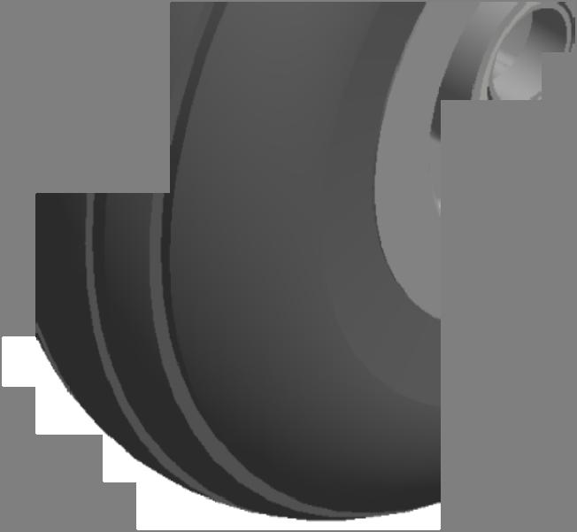
1 BAC BRACKETT AIRCRAFT COMPANY INC. BDW-BELL-A COMPLETE WHEEL SET USE ON: BELL LONGRANGER 0L, 0 GTOW:,000 LBS. LENGTH: N/A COLOR: ORANGE SHIPPING: " X " X LBS. (A SET IS TWO BOXES) 0 0 ATTACH SPINDLE TO UPPER HOLES ITEM 0 0 QTY W-BELL-00 W-BELL-0 W-BELL-0 W-BELL-0 W-0- W-0- W-HUF-0 W-HUF-0EB W--A W-00 W-- W--A 0K AN0-L A 0A0 K 00A0 0A0 A A0 CL--BLPB-.00 W-HUF- A 0A A A0 A0 A PART NUMBER PARTS LIST DESCRIPTION WELDED FRAME ASM. AXLE SLIDE ROUGH BACK ROUGH BACK GUIDE LEFT GUIDE JACK BASE JACK WITH BOLT KIT BASIC SPINDLE TIRE/WHEEL ASSEMBLY RING CASTLE NUT /- ZERK FITTING / WASHER SHIM S.S. / I.D..00 THICK /- THIN HEX LOCKNUT / I.D. / O.D. / HIGH BRONZE BUSHING / X / FENDER WASHER / LOCK WASHER / X / COTTER PIN / X / ALUM. POP RIVET / X BALL LOCK PIN HANDLE ASSEMBLY / HIGH COLLAR LOCK WASHER /- X / SHCS /- X BOLT / HIGH COLLAR LOCK WASHER S. S. /-0 X / SHCS S.S. /-0 X BOLT Page of //0


2 BAC BRACKETT AIRCRAFT COMPANY INC. W-00 TIRE/WHEEL ASSEMBLY ITEM QTY W-00TB W-00TR W-00WH PART NUMBER PARTS LIST DESCRIPTION INNER TUBE.00- WITH TR- VALVE.00 X PLY TIRE WHEEL ASSEMBLY Page of //0
3 BAC BRACKETT AIRCRAFT COMPANY INC. W-00WH WHEEL ASSEMBLY 0 ITEM 0 QTY W-00WH- W-00WH- 0- VH- LM0 LM00 C0 AN-A AN0- MS0- PART NUMBER PARTS LIST DESCRIPTION OUTER WHEEL HALF INNER WHEEL HALF FELT WASHER SNAP RING BEARING BEARING CUP. O.D.. I.D..0 WASHER S.S. /- X / CAD PLATED BOLT / WASHER /- LOCK NUT Page of //0


4 BAC BRACKETT AIRCRAFT COMPANY INC. W-HUF-0EB JACK WITH BOLT KIT JAN. 0 NORCO JACK "B" MODEL INTRODUCED. PLEASE IDENTIFY YOUR JACK MODEL BEFORE ORDERING REPLACEMENT PARTS. ITEM N.S. N.S. N.S. QTY OPT. OPT. OPT. PART NUMBER W-HUF-0EB-0 W-HUF-0-0 W-HUF-0DB-0 A0 A0 0A0 AN0- A K 000 AW ISO W-HUF-0-0D PARTS LIST DESCRIPTION HYDRAULIC JACK VALVE STEM ALUMINUM ARM KNOB /- THREADED MM X MM M THREAD SHOULDER BOLT M THREAD MM X MM SHOULDER BOLT M.MM PITCH LOCK NUT / WASHER 0- X / CAP SCREW S.S. BUNA-N / - 0 O-RING JACK #0B, SEAL KIT (#000) HYDRAULIC JACK OIL HARDWARE KIT Page of //0

5 INSTALLATION BDW-BELL-A NOTE: Always store the wheels in a well-protected area where they will not be exposed to inclement weather, corrosive vapors, abrasive dust, or any other harmful elements.. Before placing wheels on skid tube: PRE-CHECK Worn Tires replace when less than / (.mm) tread Check easy to roll no bearing noise Look at welds for cracks Check frame for damage Check tire pressure 0 PSI Jack Oil NO leaks on Frame base The wheels are mounted on the skid tube with the Jack Handle pointing FORWARD. To roll the wheels o Thread Jack handle into the handle holder, as shown. o Turn jack release knob counter clockwise ½ turn never more than turns. o Lift the jack frame up and tighten jack release knob the carrier should be above the ground. o Use handle to steer the wheels out to the helicopter.. At the helicopter: Lift the wheels over the skid tubes lifting eyes. Turn jack knob ½ turn to release pressure. Push the frame down & forward sliding carrier front nose pin into skid tube mounting hole. Finish by pushing rear carrier over the mounting hole & insert the ball lock pin thru the carrier & skid tube mount. Tighten jack release knob until it stops. (DO NOT OVER TIGHTEN) Place handle into jack link and pump until jack reaches bottom of frame. (DO NOT KEEP JACKING AFTER THE JACK REACHES BOTTOM OF FRAME DAMAGE CAN OCCUR) Remove handle and store in handle holder. This prevents the handle from falling out during towing. Removal of Wheels. Be sure nothing is under the skid tubes, LIKE YOUR TOES. Turn jack release knob counter clockwise VERY, VERY SLOWLY. Once the skid tubes are secure on the ground, rock the frame back and forth to relieve any pressure. Slide frame AFT & up to remove from skid tube. Roll back to storage. FAILURE TO FOLLOW ANY OF THE ABOVE PROCEDURES MAY CAUSE FAILURE OF THE UNIT AND CREATE HAZARDOUS TOWING CONDITIONS RESULTING IN DAMAGE TO THE AIRCRAFT AND CAN INJURE PERSONNEL AROUND THE AIRCRAFT 0 FLIGHTLINE DRIVE KINGMAN, AZ 0 PH: --00 FAX: -- WEBSITE: Page of
 tread.")
. JACK See Jack Preventative Maintenance Add AW ISO Hydraulic Jack Oil as necessary using oil filler plug.")
6 MAINTENANCE INSTRUCTION BDW-BELL-A TIRES See Tire/Wheel Inspection Air pressure maintained at 0 PSI for STA X.00/ ( ply). Grease wheel bearings every months or as needed with wheel bearing grease Aeroshell #. Replace tires when less than / (.mm) tread. FRAME Check all welds for cracks or deformities For repairs call Brackett Aircraft. Secure all bolts. Paint areas of loose or missing paint to prevent rusting. Grease slides and guides every months or as needed, USE AEROSHELL ( MS). JACK See Jack Preventative Maintenance Add AW ISO Hydraulic Jack Oil as necessary using oil filler plug. Add oil up to bottom of hole when level. It should not be necessary to refill or top off the reservoir with jack oil unless there is an external leak. An external leak requires immediate repair which must be performed in a dirt-free environment by qualified hydraulic repair personnel who are familiar with this equipment. NEVER USE ALCOHOL, HYDRAULIC BRAKE FLUID, AIRCRAFT HYDRAULIC FLUID #0 OR TRANSMISSION OIL IN THE JACK. NOTE: The jack must be lubricated periodically in order to prevent premature wearing of parts. A general-purpose grease must be applied to the three rivets/bolts that are part of the handle receiver and pump assembly. ****FAILURE TO FOLLOW ANY OF THE ABOVE PRECEDURED MAY CAUSE FAILURE OF THE UNI AND CREATE HAZARDOUS TOWING CONDITIONS RESULTING IN DAMAGE TO THE AIRCRAFT AND CAN INJURE PERSONNEL AROUND THE AIRCRAFT**** PH: --00 FAX: -- INFO@BRACKETTAIRCRAFT.COM WEBSITE: Page of
7 A MAINTENANCE INSTRUCTION WHEEL AND TIRE MAINTENANCE A Part Numbers: W-0, W-0, W-000, W-00 This section covers the removal, disassembly, inspection, reassembly, and installation of the wheel assemblies. When conducting wheel maintenance, observe the following general cautions: Careful handling of the wheel components will assure a long service life and trouble-free operation. Strictly observe the tire deflation and inflation procedures, and the torque values specified. Do not overtighten any bolt, nut, or fitting. Do not employ impact or power wrenches to remove or tighten any threaded parts. Handle the wheel bearing cones with extreme care. Many bearing failures can be traced to dropping or mishandling the cones during maintenance. Bearing cups and cones should be used as a matched set to provide maximum service life. Do not drive bearing cones onto the wheel axle, and never overtighten the axle nut. The wheel halves should be properly maintained to protect the paint and surface finishes; exposed aluminum/magnesium is susceptible to corrosion. Nicks, scratches, and other damage caused by improper handling of the wheel halves during maintenance invite corrosion which, if unattended, could lead eventually to fatigue cracks and wheel failure. Wheel Removal from Frame Housing and Disassembly ) Remove hubcap / wheel cover, if applicable. ) Remove cotter pin and axle nut. a) Rock wheel / tire slightly to unset bearings and remove. ) Place wheel / tire assembly on a clean flat surface. ) Remove air from tire by depressing the valve stem plunger until air can no longer be heard escaping from the tire. WARNING: DO NOT ATTEMPT TO REMOVE VALVE CORE UNTIL TIRE HAS BEEN COMPLETELY DEFLATED. VALVE CORES WILL BE EJECTED AT HIGH VELOCITIES IF UNSCREWED BEFORE AIR PRESSURE HAS BEEN RELEASED. 0 FLIGHTLINE DRIVE KINGMAN, AZ 0 PH: --00 FAX: -- WEBSITE: Page of
8 A MAINTENANCE INSTRUCTION WHEEL AND TIRE MAINTENANCE Part Numbers: W-0, W-0, W-000, W-00 A ) Remove valve core. ) Remove bolts, nuts, and washers holding the wheel halves together. Separate the inner and outer wheel halves and remove tire. Remove retaining rings and drive grease seals from wheel halves with a suitable drift. Remove bearing cones and store carefully to avoid damage or contamination. The bearing cup is a shrink fit into the wheel half and SHOULD NOT BE REMOVED, UNLESS REPLACEMENT IS NECESSARY due to scratches, nicks, pitting, corrosion, or evidence of overheating. If bearing cup replacement is necessary, place wheel half in an oven degrees F for 0 minutes. a) Remove wheel half from heat source and immediately remove bearing cup. If bearing cup does not fall out, tap it evenly with a suitable drift pin or use a hydraulic press. WARNING: WHEEL HALVES WILL REMAIN VERY HOT. PROTECTIVE GLOVES ARE REQUIRED. Wheel Inspection ) Visually inspect wheel halves for cracks, nicks, corrosion, or other damage. Any cracks in the wheel half are cause for replacement of wheel half. The tire bead seat area of a wheel is typically an area of stress concentration and possibly subjected to trauma from tire beads and tools used to remove tires. Special attention should be taken in this area when inspecting for defects. All defect indications must be thoroughly investigated to determine part airworthiness. Dye penetrant inspection and visual examination is an effective method to evaluate a defect indication. To facilitate the inspection process, it is recommended that the paint be stripped in the area being evaluated. Replace any cracked or excessively corroded parts. Small nicks, scratches, or pits may be blended out and polished with fine sandpaper. Treat and repaint to original condition. ) Inspect wheel bearing cup bore for burrs, primer residue, or foreign matter. Make sure surface is clean. Inspect retaining ring and grease seals for distortion and wear. ) Replace grease felts if they are hard or contaminated. Molded rubber grease seals should be replaced if cracked, dried out, or distorted. 0 FLIGHTLINE DRIVE KINGMAN, AZ 0 PH: --00 FAX: -- WEBSITE: Page of
9 A MAINTENANCE INSTRUCTION WHEEL AND TIRE MAINTENANCE A Part Numbers: W-0, W-0, W-000, W-00 ) Wheel tie bolts must be inspected for cracks, bending, thread damage, or excessive corrosion. If any evidence is seen on bolt replace. ) Inspect self-locking nut for damage. If nut can be turned onto bolt by hand, past the nut s selflocking section, it should be replaced. Wheel Assembly Reassembly of the wheel assembly is essentially the reverse of the disassembly procedures. Assemble the wheel on a clean flat surface and be careful with components. ) If bearing cup was removed, heat wheel half to degrees F for minutes and chill bearing cup -0 degrees F for no less than hours. ) Install the chilled bearing cup into bearing bore of heated wheel half. Tap with fiber drift evenly against shoulder seat. Avoid cocking bearing cup during installation. ) Use Aeroshell # (or equivalent) to pack bearing cone and lightly grease felt seals. Properly greased bearings should have no voids between rollers. Then assemble into wheel half with snap ring SEE PARTS LIST. Remove excess grease. ) Make sure the inside of the tire is clean and dry. Wipe bead area with denatured alcohol, followed by soap and water. ) Inflate tube just enough to round it out. Then install yellow strip adjacent to the red spot on tire. If no mark on tube, use red spot opposite of valve stem. ) Install the tire and inner tube on outer wheel half, inserting the valve stem through the valve hole. Place inner wheel half inside the tire. Align the makes made at disassembly with those on outer wheel half. ) Install bolts, washers on outside wheel half and the washers nuts on inner wheel half. a) Torque dry ¼ 0-00 in-lbs b) Torque dry / 0-0 in-lbs ) Fill with air to recommended air pressure. 0 FLIGHTLINE DRIVE KINGMAN, AZ 0 PH: --00 FAX: -- WEBSITE: Page of
10 TIRE PREVENTATIVE MAINTENANCE Tire/Wheel Inspection: Any tire, no matter how well constructed, may fail as a result of punctures, impact damage, improper inflation, overloading, or other conditions resulting from use or misuse. Tire failure may create a risk of property damage and serious personal injury. To reduce risk of tire failure, we strongly recommend you read and follow all safety information. Inspect wheels and tires for wear, cracks, cuts, or damage. Bumps or bulges may indicate separation within the tire body. A damaged tire can suddenly fail causing damage to property or serious personal injury. Inspect tire for adequate tread depth / nd inch (. millimeters). Tire Inflation: Always keep tire inflated to the manufactures recommended pressure. Tire sidewall stamping information will tell you the recommended cold air pressure. Check tire inflation before moving aircraft. Air Hawk X.00 ply psi Air Hawk X.0 ply 0 psi Carlisle.0/.0- ply psi Kenda.0/.0- ply psi Kenda.0/.0- ply 0 psi STA X.00- ply 0 psi Air Hawk :00-0 ply 0 psi Use valve caps to keep valve cores clean, clear of debris and to help guard against air leakage. Under-inflated tires will cause damage leading to failure that could result in damage to property or serious personal injury. Over-inflated tires are more likely to become punctured, cut, or broken by sudden impact leading to failure that could result in damage to property or serious personal injury. PH: --00 FAX: -- INFO@BRACKETTAIRCRAFT.COM WEBSITE: Page 0 of
11 A MAINTENANCE INSTRUCTION A JACK PREVENTATIVE MAINTENANCE Always store equipment in a well-protected area where it will not be exposed to inclement weather, corrosive vapors, abrasive dust, or any other harmful elements. Jack must be cleaned of water, snow, sand, or grit before using. Jack must be lubricated periodically in order to prevent premature wearing of parts. A general-purpose grease must be applied to handle base pivot bolts, release mechanism and all other bearing surfaces. It should not be necessary to refill or top off the reservoir with hydraulic fluid unless there is an external leak. An external leak requires immediate repair which must be performed in a dirt-free environment by qualified hydraulic repair personnel who are familiar with this equipment. Use a high grade hydraulic/jack oil ISO to add fluid. IN ORDER TO PREVENT SEAL DAMAGE AND JACK FAILURE, NEVER USE ALCOHOL, HYDRAULIC BRAKE FLUID, OR TRANSMISSION OIL IN THE JACK. Inspect the jack before each use. Do not use the jack if any component is cracked, broken, bent, shows signs of damage, or leaks hydraulic fluid. Do not use the jack if it has loose or missing hardware or components. Do not attempt to make any hydraulic repairs unless you are a qualified hydraulic repair person that is familiar with this equipment. Available Oil for Jack: Part No: AW ISO QT Available Seal Kits: Ton Jack (W--A) Ton Jack (W-HUF-0D/EB) Ton Jack (W--D/F/G) Part No: 00 Part No: 000 Part No: FLIGHTLINE DRIVE KINGMAN, AZ 0 PH: --00 FAX: -- WEBSITE: Page of
BRACKETT AIRCRAFT COMPANY
 BAC BRACKETT AIRCRAFT COMPANY www.brackettaircraft.com INC. BDW-0LRH HYDRAULIC WHEEL ASM. USE ON: BELL LONG RANGER 0L, 07 GTOW:,00 LBS. LENGTH: N/A COLOR: ORANGE SHIPPING: BOXES " X 0" X " @ 0 LBS. Page
BRACKETT AIRCRAFT CO., INC. HYDRAULIC WHEEL LIFT
 BAC BAC H H 0 FLIGHTLINE DR. KINGMAN, AZ 0 9--00 BRACKETTAIRCRAFT.COM HYDRAULIC WHEEL LIFT G G 9 F 0 F E E 0 9 D LIFT PART NUMBER TY-TBW-RD TY-TBW-RD APPLICABLE TOW BAR TYPE " ROUND PIPE " ROUND PIPE D
INSTRUCTIONS FOR CONTINUED AIRWORTHINESS
 INSTRUCTIONS FOR CONTINUED AIRWORTHINESS for GROVE MODEL 40-108 & 40-208 MAIN WHEELS DOCUMENT 12012-12 REV IR January 16, 2012 TABLE OF CONTENTS SECTION PAGE Title Page...1 Table of Contents...2 Record
COMPONENT MAINTENANCE MANUAL AND INSTRUCTIONS FOR CONTINUED AIRWORTHINESS FOR AEROCET 5.00 X 6.00 (6
 PRIEST RIVER, ID. (208) 448-0400 Component Maintenance Manual & ICA A-10036 5.00 X 6.00 (6.00-6) WHEEL ASSEMBLY, OIL BATH, AND GREASE PACK TYPES COMPONENT MAINTENANCE MANUAL AND INSTRUCTIONS FOR CONTINUED
ABI WHEEL & BRAKE KIT
 INSTALLATION INSTRUCTIONS and INSTRUCTIONS FOR CONTINUED AIRWORTHINESS for the installation of ABI-199-62 WHEEL & BRAKE KIT for CESSNA AIRCRAFT SERIES 180, 185, 206 Doc No.: ABI-199-62-4 REV B 04/21/2017
INSTRUCTIONS CONTINUED AIRWORTHINESS
 INSTRUCTIONS FOR CONTINUED AIRWORTHINESS FOR GROVE MAIN WHEEL AND BRAKE ASSEMBLIES WITH FAA-TSO APPROVAL DOCUMENT 13046-11 Rev C April 29, 2018 TABLE OF CONTENTS SECTION PAGE Title Page... 1 Table of Contents...
WHEELS 1. DESCRIPTION A.
 WHEELS 1. DESCRIPTION A. Main Wheels Serials 22-0002 thru 22-4045 before SB2X-32-21, 22T-0001 thru 22T-0689 before SB2X-32-21: The main wheels are of aluminum construction and designed to be used with
2 TON CAPACITY PROFESSIONAL SERIES ALUMINUM JACK OWNER'S MANUAL SPECIFICATIONS
 80006 OWNER'S MANUAL CONTENTS: Page 1 Specifications 2 Warning Information 3 Setup, Operating and Preventative Maintenance 4 Troubleshooting 5 Maintenance 6 Exploded View Drawing and Replacement Parts
Instructions for Continued Airworthiness
 Instructions for Continued Airworthiness for GROVE 28-4001 AND 28-4001A WHEEL AND BRAKE CONVERSION KITS in all PIPER AIRCRAFT INCLUDED IN THE FAA APPROVED MODEL LIST when installed In Accordance With Supplemental
Air / Hydraulic Under Axle Jack
 655 Eisenhower Drive Owatonna, MN 55060-0995 USA Phone: (507) 455-7000 Tech. Serv.: (800) 533-6127 Fax: (800) 955-8329 Order Entry: (800) 533-6127 Fax: (800) 283-8665 International Sales: (507) 455-7223
High Lift Transmission Jack
 655 Eisenhower Drive Owatonna, MN 55060 USA Phone: (507) 455-7000 Tech. Serv.: (800) 533-6127 Fax: (800) 955-8329 Order Entry: (800) 533-6127 Fax: (800) 283-8665 International Sales: (507) 455-7223 Fax:
COMPONENT MAINTENANCE MANUAL FOR AEROCET WHEEL ASSEMBLIES, OIL BATH, AND GREASE PACK TYPE; AND AEROCET BRAKE ASSEMBLY
 COMPONENT MAINTENANCE MANUAL FOR AEROCET, AND GREASE PACK TYPE; AND AEROCET BRAKE ASSEMBLY TITLE PAGE pg. i 32-00-01 Revision 2 This page intentionally left blank. TITLE PAGE pg. ii 32-00-01 Revision 2
Low Lift Transmission Jack
 655 Eisenhower Drive Owatonna, MN 55060 USA Phone: (507) 455-7000 Tech. Serv.: (800) 533-6127 Fax: (800) 955-8329 Order Entry: (800) 533-6127 Fax: (800) 283-8665 International Sales: (507) 455-7223 Fax:
BRACKETT AIRCRAFT COMPANY
 RKETT IRRFT OMPNY www.brackettaircraft.com IN. W-MH-SW OMPLETE SSEMLY USE ON: M MH- GTOW: LENGTH: N/ OLOR: FLT LK SHIPPING: OXES " X 0" X " @ 0 LS. E. Page of 0//00 RKETT IRRFT OMPNY, IN. INSTLLTION &
Racing Jack Max. Capacity: 3,000 lbs. (1,361 kg)
") R SPX Corporation 655 Eisenhower Drive Owatonna, MN 55060-0995 USA Phone: (507) 455-7000 Tech. Serv.: (800) 533-6127 Fax: (800) 955-8329 Order Entry: (800) 533-6127 Fax: (800) 283-8665 International Sales:
R SPX Corporation 655 Eisenhower Drive Owatonna, MN 55060-0995 USA Phone: (507) 455-7000 Tech. Serv.: (800) 533-6127 Fax: (800) 955-8329 Order Entry: (800) 533-6127 Fax: (800) 283-8665 International Sales:
Air Assist Bottle Jack Max. Capacity: 12 Tons (4313C) & 20 Tons (4321C) Operating Range: psi
 & 20 Tons (4321C) Operating Range: psi") Form No. 545742 Parts List and Operating Instructions for: 4313C 4321C Air Assist Bottle Jack Max. Capacity: 12 Tons (4313C) & 20 Tons (4321C) Operating Range: 40 150 psi 45 44 43 42 41 40 39 22 1 37 28
Form No. 545742 Parts List and Operating Instructions for: 4313C 4321C Air Assist Bottle Jack Max. Capacity: 12 Tons (4313C) & 20 Tons (4321C) Operating Range: 40 150 psi 45 44 43 42 41 40 39 22 1 37 28
6722 Rev. A CAPACITY: 22 TON TRUCK AXLE JACK WITH AIR RETURN
 CONTENTS: Page Specifications 2 Warning Information Setup Instructions and Operating Instructions 4 Preventative Maintenance, Inspection and Proper Storage 5 Troubleshooting, Owner/User Responsibility
Service Jacks. Operating Instructions & Parts Manual. Model Number. Capacity 4 Ton 4 Ton Air/ Manual 10 Ton 10 Ton Air/ Manual HW93657/ HW93660
 Service Jacks Operating Instructions & Parts Manual Model Number HW93657 HW93667 HW93660 HW93662 Capacity 4 Ton 4 Ton Air/ Manual 10 Ton 10 Ton Air/ Manual Made in North America HW93657/ HW93660 HW93667/
6602LP CAPACITY: 2 TON LOW RIDER SERVICE JACK
 CONTENTS: Page 1 Specifications 2 Warning Information 3 Setup Instructions 4 Operating Instructions, Preventative Maintenance, Inspection and Proper Storage 5 Hydraulic Jack Maintenance Guide and Regular
jegs.com. Installation Instructions for Ton Aluminum Floor Jack
 Installation Instructions for 80077 3-Ton Aluminum Floor Jack Contents: Specifications Warning Information Setup and Operating Instructions Preventive Maintenance and Troubleshooting Hydraulic Maintenance
SPECIFICATIONS SPECIFICATIONS
 4430 and 4450 OWNER'S MANUAL CONTENTS: Page 1 Specifications 2 Warning Information 3 Setup and Operating Instructions 4 Preventative Maintenance and Troubleshooting 5 4430 Exploded View Drawing and Parts
Air-Assist Service Jack Max. Capacity: 10 Tons
 Form No. 565786 Parts List & Operating Instructions for: 1511B Air-Assist Service Jack Max. Capacity: 10 Tons 109 67 66 68 77 69 70 78 95 94 107 106 108 26 71 72 72 93 X L 65 75 92 91 90 89 88 87 86 85
Service Jack. Form No Parts List & Operating Instructions 1510B. Max. Capacity: 5 and 10 Tons. 1 of 3. Sheet No. Issue Date: Rev.
 SPX Corporation 655 Eisenhower Drive Owatonna, MN 55060-0995 USA Phone: (507) 455-7000 Tech. Serv.: (800) 533-6127 Fax: (800) 955-8329 Order Entry: (800) 533-6127 Fax: (800) 283-8665 International Sales:
AV A IM V 103D Aircraft Wheels
 AVIM 103D Aircraft Wheels Aircraft Wheels Aircraft Wheels Usually two piece Two opposing conical tapered bearings for each wheel Can be tube type or tubeless Tubeless will have seal rings or sealing compound
500kg TELESCOPIC TRANSMISSION LIFTER
 Product Code: 2056T PRODUCT CODE: 2056T 500kg TELESCOPIC TRANSMISSION LIFTER Safe Working Capacity 500kg Base Dimension 540 x 570 mm Minimum Height 1175mm Maximum Height 1900mm Made in China to TQB Brands
WARNING SPECIFICATIONS MODEL # A 1-1/2 TON TRANSMISSION JACK. Manufactured to comply with the ASME PASE-2014 Safety Standard.
 MODEL # 791-7180 A 1-1/2 TON TRANSMISSION JACK BEFORE USING THIS DEVICE, READ THIS MANUAL COMPLETELY AND THOROUGHLY, UNDERSTAND ITS OPERATING PROCEDURES, SAFETY S AND MAINTENANCE REQUIREMENTS. It is the
Air Assist Bottle Jack Max. Capacity: 12 Tons (4313C) & 20 Tons (4321C) Operating Range: psi
 & 20 Tons (4321C) Operating Range: psi") R SPX Division 655 Eisenhower Drive Owatonna MN 55060 Phone: (507) 455-7000 Tech. Serv.: (800) 533-6127 Fax: (800) 955-8329 Order Entry: (800) 533-6127 Fax: (800) 283-8665 International Sales: (507) 455-7223
R SPX Division 655 Eisenhower Drive Owatonna MN 55060 Phone: (507) 455-7000 Tech. Serv.: (800) 533-6127 Fax: (800) 955-8329 Order Entry: (800) 533-6127 Fax: (800) 283-8665 International Sales: (507) 455-7223
MODCO TM FIGURE 500 CLOSURE
 CLOSURE SPECIALISTS SINCE 1981 MODCO TM FIGURE 500 CLOSURE INSTALLATION INSTRUCTIONS (!) THE INFORMATION PROVIDED IN THIS DOCUMENT IS VERY IMPORTANT (!) & (!) needs to be shared with everyone involved
Wheel end service for greased wheel ends
 wheel ends Page 1 Tech tip Scope This document recommends procedures for servicing greased wheel ends. Included are SKF recommendations for manually adjusted, hard greased (NLGI 1, 2, and 3) and semi-fluid
Forklift Jack. Scissors Max. Capacity: 4 ton Scissors Low Height: 2-5/32 in. (55 mm) Scissors High Height: 17-29/32 in. (455 mm)
 Scissors High Height: 17-29/32 in. (455 mm)") 655 Eisenhower Drive Owatonna, MN 55060 USA Phone: (507) 455-7000 Tech. Serv.: (800) 533-6127 Fax: (800) 955-8329 Order Entry: (800) 533-6127 Fax: (800) 283-8665 International Sales: (507) 455-7223 Fax:
655 Eisenhower Drive Owatonna, MN 55060 USA Phone: (507) 455-7000 Tech. Serv.: (800) 533-6127 Fax: (800) 955-8329 Order Entry: (800) 533-6127 Fax: (800) 283-8665 International Sales: (507) 455-7223 Fax:
Maintenance Information
 16573370 Edition 2 February 2014 Air Grinder 99V Series Maintenance Information Save These Instructions Product Safety Information WARNING Failure to observe the following warnings, and to avoid these
SPECIFICATIONS CONTENTS:
 Model 3052A 1,100 Lbs Air Assist 2 Stage Transmission Jack INSTRUCTION MANUAL CONTENTS: Page 1 Specifications Page 2 Warning Information Page 3 Assembly Page 4 Operating Instructions Page 4 Preventative
Long Chassis Hydraulic Service Jacks
 Long Chassis Hydraulic Service Jacks Operating Instructions & Parts Manual Model Number Atd-7390 Atd-7391 Capacity 5 Ton 10 Ton Atd Tools Inc. 160 Enterprise Drive, Wentzville MO 63385 Printed in China
SECTION ZF FRONT AXLE
 04-101.01/ 1 2011JA14 SECTION 04-101.01 6 3 5 1 2 9 1. Upper radius rod 2. Lower radius rod 3. Caliper 4. BRAKE Disk 5. Pneumatic connector 6. Hub 7. steering knuckle 8. Grease Fitting 9. Pneumatic connector
Under Axle Jack Max. Capacity: 25 Tons
 SPX Corporation 655 Eisenhower Drive Owatonna, MN 55060-0995 USA Phone: (507) 455-7000 Tech. Serv.: (800) 533-6127 Fax: (800) 955-8329 Order Entry: (800) 533-6127 Fax: (800) 283-8665 International Sales:
Operating Instructions 20 Ton Air/Hydraulic Service Jack
 MODEL: 3225 Operating Instructions 20 Ton Air/Hydraulic Service Jack WARNING: Important: Read these instructions and all warnings prior to using this equipment. Understand all operating procedures, safety
SPECIFICATIONS CONTENTS:
 Model 3052 1,100 Lbs 2 Stage Transmission Jack INSTRUCTION MANUAL CONTENTS: Page 1 Specifications Page 2 Warning Information Page 3 Assembly Page 4 Operating Instructions Page 4 Preventative Maintenance
Service Jacks. No. 1503A Max. Capacity: 2-1/2 Tons No. 1504A Max. Capacity: 3 Tons. Service Jack Item List
 SPX Corporation 655 Eisenhower Drive Owatonna, MN 55060-0995 USA Phone: (507) 455-7000 Tech. Serv.: (800) 533-6127 Fax: (800) 955-8329 Order Entry: (800) 533-6127 Fax: (800) 283-8665 International Sales:
SECTION 7 - SUSPENSION
 For Arctic Cat Discount Parts Call 606-678-9623 or 606-561-4983 SECTION 7 - SUSPENSION 7 TABLE OF CONTENTS Front and Rear Suspension Assembly Schematics... 7-2 Shock Absorbers... 7-2 Swing Arm... 7-5 Front
Hydraulic Hand Pallet Trucks
 Operating Instructions & Parts Manual 12U124 Please read and save these instructions. Read carefully before attempting to assemble, install, operate, or maintain the product described. Protect yourself
Air / Hydraulic Floor Service Jack
 SPX Corporation 655 Eisenhower Drive Owatonna, MN 55060-0995 USA Phone: (507) 455-7000 Tech. Serv.: (800) 533-6127 Fax: (800) 955-8329 Order Entry: (800) 533-6127 Fax: (800) 283-8665 International Sales:
Air Actuated Hydraulic Bottle Jacks
 Air Actuated Hydraulic Bottle Jacks Operating Instructions & Parts Manual Model Number Atd-7412 Atd-7420 Capacity 12 Ton 20 Ton Atd Tools Inc. 160 Enterprise Drive, Wentzville MO 63385 Printed in China
Maintenance Information
 16573347 Edition 2 February 2014 Air Grinder Series 88H Maintenance Information Save These Instructions Product Safety Information WARNING Failure to observe the following warnings, and to avoid these
Wheels Brakes Tires Hydraulic hoses/ fittings Landing Gear SPARE PART CATALOGUE. Price list EURO
 Wheels Brakes Tires Hydraulic hoses/ fittings Landing Gear SPARE PART CATALOGUE Price list EURO GENERAL MAINTENANCE AND INSTALLATION MANUAL The instructions detailes following are general instruction concerning
Air / Hydraulic Floor Service Jack
 655 Eisenhower Drive Owatonna, MN 55060 USA Phone: (507) 455-7000 Tech. Serv.: (800) 533-6127 Fax: (800) 955-8329 Order Entry: (800) 533-6127 Fax: (800) 283-8665 International Sales: (507) 455-7223 Fax:
Installation, Operating and Maintenance Instructions. Rotating Machine Screw Actuators. With Parts List Publication Part No.
 Installation, Operating and Maintenance Instructions With Parts List Publication Part No. SK-2389-R1 Rotating Machine Screw Actuators 1/4 Through 1-Ton Capacity Caution This manual contains important information
SPECIFICATIONS CONTENTS: Warning Information. Operating Instructions Preventative Maintenance and Troubleshooting
 Model 3322 22 Ton Air/Hydraulic Truck Axle Jack OWNER'S MANUAL CONTENTS: Page 1 Page 2 Page 3-4 Page 4-5 Page 5 Page 6 Page 7 Page 8 Specifications Warning Information Assembly Operating Instructions Preventative
DESCRIPTION Acura TSX SUSPENSION Front - TSX. NOTE: For system description and component location, see Fig. 1.
 2004 SUSPENSION Front - TSX DESCRIPTION NOTE: For system description and component location, see Fig. 1. Fig. 1: Identifying Front Suspension Components Wednesday, March 12, 2008 8:30:45 8:30:55 PM Page
Motorcycle/ATV Lift. Max. Capacity: 1,500 lbs. Parts List
 SPX Corporation 655 Eisenhower Drive Owatonna, MN 55060-0995 USA Phone: (507) 55-7000 Tech. Serv.: (800) 533-627 Fax: (800) 955-89 Order Entry: (800) 533-627 Fax: (800) 283-8665 International Sales: (507)
Hydraulic Clutch Jack
 Hydraulic Clutch Jack Operating Instructions & Parts Manual Model Number Atd-7404 Capacity 500 Lb. Atd Tools Inc. 160 Enterprise Drive, Wentzville MO 63385 Printed in China ATD7404-M0 05/07 Save these
INSPECTION & MAINTENANCE BULLETIN ARI 1301/1302 1" Plug Type Angle Valves
 INSPECTION & MAINTENANCE BULLETIN ARI 1301/1302 1" Plug Type Angle Valves Item # Description Item # Description 1 Body 12 Washer 2 Packing Retainer 13 Bushing 3 Packet Set 14 Bolt 4 Jam Nut 15 Yoke 5 Stud
Hydraulic Transmission Jacks
 Hydraulic Transmission Jacks Operating Instructions & Parts Manual Model Number Atd-7435 Atd-7436 Atd-7437 Capacity 1100 Lb. 2000 Lb. 3000 Lb. Model Atd-7435 Model Atd-7436 Model Atd-7437 Atd Tools Inc.
HEAVY DUTY TROLLEY JACK. Operation Manual
 HEAVY DUTY TROLLEY JACK 4T Operation Manual Make sure to read and fully understand the instruction manual before using this product and keep the manual properly 1 General Description Product Description
BOGERT HMMWV LIFTING JACK KIT PART NR: 30M-HVBMI NSN:
 BOGERT HMMWV LIFTING JACK KIT PART NR: 30M-HVBMI NSN: 5120-01-573-3382 Tire Replacement Jack Operating Instructions Model: 30M-HV Jack with BMI P40A Hydraulic Pump Bogert International Inc. 3606 N. Swallow
SECTION 6 3 SERVICE PROCEDURES AND SPECIFICATIONS. Chassis
 SECTION 6 3 SERVICE PROCEDURES AND SPECIFICATIONS Chassis Specifications 206 Checking brake fluid 208 Checking power steering fluid 209 Checking tire pressure 210 Rotating tires 211 Checking and replacing
TECHNICAL BULLETIN. TP Issued Servicing Rockwell s TB Series Trailer Axles with Unitized Hub Assemblies
 TECHNICAL BULLETIN TP-96175 Issued 12-96 Servicing Rockwell s TB Series Trailer Axles with Unitized Hub Assemblies TB Series Trailer Axles Introduction Rockwell s TB series trailer axle features a permanently
Portable Two-Stage Under Axle Jack Max. Capacity: First Stage: 27.5 Tons Second Stage: 11 Tons. Safety Precautions
 SPX Corporation Eisenhower Drive Owatonna, MN 00-0 USA Phone: (07) -7000 Tech. Serv.: (00) -7 Fax: (00) - Order Entry: (00) -7 Fax: (00) - International Sales: (07) -7 Fax: (07) -70 Form No. Parts List
1988 Chevrolet Pickup V SUSPENSION - FRONT (4WD)' 'Front Suspension - "V" Series 1988 SUSPENSION - FRONT (4WD) Front Suspension - "V" Series
' 'Front Suspension - V Series 1988 SUSPENSION - FRONT (4WD) Front Suspension - V Series") 1988 SUSPENSION - FRONT (4WD) Front Suspension - "V" Series DESCRIPTION NOTE: Vehicle serial numbers used in this article has been abbreviated for common reference to Chevrolet and GMC models. Chevrolet
1988 SUSPENSION - FRONT (4WD) Front Suspension - "V" Series DESCRIPTION NOTE: Vehicle serial numbers used in this article has been abbreviated for common reference to Chevrolet and GMC models. Chevrolet
BRAKE SYSTEM Return To Main Table of Contents
 BRAKE SYSTEM Return To Main Table of Contents GENERAL... 2 BRAKE PEDAL... 10 MASTER CYLINDER... 13 BRAKE BOOSTER... 16 BRAKE LINE... 18 PROPORTIONING VALVE... 19 FRONT DISC BRAKE... 20 REAR DRUM BRAKE...
WHEELS BEARINGS TIRES
 GROUP 22 WHEELS BEARINGS TIRES CONTENTS Page GENERAL INFORMATION 1 SERVICE DIAGNOSIS 1 SERVICE PROCEDURES... 2 WHEELS... 2 Page BEARINGS 2 TIRES 4 SPECIFICATIONS AND TIGHTENING REFERENCE.. In Rear of Manual
Operation and Maintenance Instructions
 Hydratight Limited Bentley Road South Darlaston West Midlands WS10 8LQ United Kingdom Tel: +44 121 50 50 600 Fax: +44 121 50 50 800 E-mail: enquiry@hydratight.com Website: www.hydratight.com TOP COLLAR
OWNER S MANUAL PRODUCT CODE: 2006T
 Jul-18 Product Code: 2006T OWNER S MANUAL PRODUCT CODE: 2006T HYDRAULIC PIPE BENDER 12,000KG Model Capacity Bending Die No of Attachments 12,000kg 1/2", 3/4", 1", 1-1/4", 1-1/2", 2" 6 Made in China to
INSTALLATION AND OPERATION MANUAL
 Tire Vulcanizer Model: RV80L VER A PLEASE READ THE ENTIRE CONTENTS OF THIS MANUAL PRIOR TO INSTALLATION AND OPERATION. BY PROCEEDING YOU AGREE THAT YOU FULLY UNDERSTAND AND COMPREHEND THE FULL CONTENTS
Installation Instructions
 Preparing your vehicle to install your brake system upgrade 1. Rack the vehicle. 2. If you don t have a rack, then you must take extra safety precautions. 3. Choose a firmly packed and level ground to
Hydraulic Long Jacks
 Operating Instructions & Parts Manual Hydraulic Long Jacks Model 44915 44930 44940 44980 44981C (Air option) Capacity 1-1/2 Ton 3 Ton 4 Ton 8 Ton 8 Ton Models 44915, 44930, 44940 & 44980 Model 44981C U.S.
Part 7 DO IT YOURSELF MAINTENANCE
 Part 7 DO IT YOURSELF MAINTENANCE Chapter 7 2 Engine and Chassis Checking the engine oil level Checking the engine coolant level Checking brake fluid Checking power steering fluid Checking tire pressure
PNEUMATIC SLIDING VALVE
 INSTALLATION, OPERATION, & #: MM-SV001 6-23-09 Rev. A Page 1 of 8 PNEUMATIC SLIDING VALVE PART NUMBERS (Including, but not inclusive) SV704MSTS, SV714MSTS, SV754MSTS, SV764MSTS, SV774MSTS, SV706MSTS, SV716MSTS,
12. FRONT WHEEL/FRONT BRAKE/
 12 4.5kgm 0.9kg-m 4.5kg-m 12-0 SERVICE INFORMATION... 12-1 HYDRAULIC BRAKE... 12-10 TROUBLESHOOTING... 12-2 FRONT SHOCK ABSORBER... 12-16 FRONT WHEEL... 12-3 STEERING HANDLEBAR... 12-19 FRONT BRAKE...
Maintenance Information
 16573321 Edition 3 February 2014 Air Grinder Series 61H Maintenance Information Save These Instructions Product Safety Information WARNING Failure to observe the following warnings, and to avoid these
TIRES AND WHEELS 22-1 TIRES AND WHEELS CONTENTS
 ZJ TIRES AND WHEELS 22-1 TIRES AND WHEELS CONTENTS TIRES... 1 WHEELS... 7 TIRES INDEX DESCRIPTION AND OPERATION RADIAL-PLY TIRES... 2 REPLACEMENT TIRES... 3 SPARE TIRE TEMPORARY... 2 TIRE INFLATION PRESSURES...
Hydraulic Transmission Jack, Telescopic
 Operating Instructions & Parts Manual Hydraulic Transmission Jack, Telescopic Model 4000 400 (Air Operated) Capacity 000 lbs. 000 lbs. Model 4000 Model 400 U.S. Patent No. 6,02,377! This is the safety
Figure 56 - Carrier Roller, Cross Section. Figure 57 - Carrier Roller, Exploded View THRUST - BUSHING HUB WASHER (1)~~~ 3/8 NC x 3/4"
~~~ 3/8 NC x 3/4") 3/8 NC x 3/4" THRUST - BUSHING 721540 Figure 56 - Carrier Roller, Cross Section HUB Figure 57 - Carrier Roller, Exploded View 1. WASHER (1)~~~ I 1/2 NC x 1-1/4"{3) 720925 5010-28 5. Remove the face seal
3/8 NC x 3/4" THRUST - BUSHING 721540 Figure 56 - Carrier Roller, Cross Section HUB Figure 57 - Carrier Roller, Exploded View 1. WASHER (1)~~~ I 1/2 NC x 1-1/4"{3) 720925 5010-28 5. Remove the face seal
Mechanical Actuators
 Mechanical Actuators Translating Machine Screw Actuators 100-Ton, 150-Ton & 250-Ton Capacity Installation, Operation & Maintenance Instructions Publication Part No. SK-2389-100 CAUTION This manual contains
Wheels. Wheels and Tires ! CAUTION. Wheel Selection
 Wheels Wheel Selection Wheels are a very important and critical component of your running gear system. When specifying or replacing your trailer wheels it is important that the wheels, tires, and axle
"Figure 2: Trim Washer" was "Figure 1: Trim Washers". Page: 40A-06 REV 1: In Step 6, added "Fully torque the nut."
 14401 Keil Road NE, Aurora, Oregon, USA 97002 PHONE 503-678-6545 FAX 503-678-6560 www.vansaircraft.com info@vansaircraft.com Service Letters and Bulletins: www.vansaircraft.com/public/service.htm REVISION
Instruction Manual For Auto Shift Hydraulic Lift Table
 Instruction Manual For Auto Shift Hydraulic Lift Table Model Number: CART-550-AS Note: Owner/Operator must read and understand this Instruction Manual before operating the lift & tilt table. Contents 1
Operating Instructions & Parts Manual. Capacity 4 Ton. 10 Ton 10 Ton
 Service Jacks Operating Instructions & Parts Manual Model Number HW93657 HW93667 (Air/Manual) HW93660 HW93662 (Air/Manual) Capacity 4 Ton 4 Ton 10 Ton 10 Ton Made in the U.S.A. Model No. HW93657 & HW93660
Best Practice Guideline. Tyre Handling in Surface Operations
 Best Practice Guideline Tyre Handling in Surface Operations www.aspasa.co.za June 2018 Introduction The job of tyre servicing can be extremely hazardous. An inflated large vehicle tyre contains tremendous
OPERATING INSTRUCTIONS & SERVICE MANUAL BLUE MAX II HYDROSTATIC TEST PUMP
 PAGE 1 OF 10 OPERATING INSTRUCTIONS & SERVICE MANUAL BLUE MAX II HYDROSTATIC TEST PUMP EFFICIENT, EASY OPERATION Air operated pump Wide range of pressures and volumes Easy to operate controls Output pressure
SECTION 6 3 SERVICE PROCEDURES AND SPECIFICATIONS. Chassis
 SERVICE PROCEDURES AND SPECIFICATIONS Chassis SECTION 6 3 Specifications........................................... 208 Checking brake fluid...................................... 210 Checking power steering
SECTION 8 2 DO IT YOURSELF MAINTENANCE. Chassis
 DO IT YOURSELF MAINTENANCE Chassis SECTION 8 2 Checking the coolant level of the traction motor................ 184 Checking the radiator....................................... 185 Checking brake fluid........................................
ASSEMBLY & OPERATION INSTRUCTION MANUAL
 Sliding Bridge Jack 3,500 lbs. Capacity ASSEMBLY & OPERATION INSTRUCTION MANUAL TABLE OF CONTENTS Specifications... 2 Description & Features... 3 Installation Instructions... 4 Safety Instructions... 4
STANDARD OPERATING PROCEDURE
 STANDARD OPERATING PROCEDURE SOP 12-01 / January 8, 2012 Rev 02/12 Rev 03/12 10/13 TO: Subject: All Fastlube Employees TIRE REPAIR PROCEDURES One of the greatest liabilities for a company providing tire
Mini Jacks Instruction Manual
 J11050-M0_062017 Instruction Manual MODELS: J11050, J11055-5 Ton Capacity J11100-10 Ton Capacity J11200-20 Ton Capacity This is the safety alert symbol. It is used to alert you to potential personal injury
INSTALLATION AND MAINTENANCE MANUAL
 IMPORTANT This manual must accompany the trailer when delivered to the end user. INSTALLATION AND MAINTENANCE MANUAL ISS Series Suspensions 347 King Street West, Ingersoll, Ontario, Canada, N5C 3K6 Ph:
Installation and Maintenance Manual Van s RV3,4,6,6A,7,7A,8,8A,9,9A,10,12,14 and 14A
 AERO FRANCE Aéropole 05130 TALLARD Tél: +33 (0)4 92 20 16 19 Fax: +33 (0)4 92 52 69 66 Van s RV3,4,6,6A,7,7A,8,8A,9,9A,10,12,14 and 14A Copyright Jean Marie Urlacher This documents contains 72 pages -
MUELLER. Super Centurion 350 Fire Hydrant. Reliable Connections. Inspection and Maintenance 2. Filling Oil Reservoir 3. Facing the Hydrant 4
 operating Instructions manual MUELLER Super Centurion 350 Fire Hydrant table of contents PAGE Inspection and Maintenance 2 Filling Oil Reservoir 3 Facing the Hydrant 4 Restoring Service after Traffic Knockover
Operation & Service Manual
 Operation & Service Manual Model: 02-1248-0112 12 Ton Single Stage Jack 11/2004 Rev. 02 Includes Illustrated Parts Lists 1740 Eber Rd Tronair, Inc. Phone: (419) 866-6301 Holland, OH 43528-9794 www.tronair.com
SD Bendix E-10PR Retarder Control Brake Valve DESCRIPTION. OPERATION - Refer to Figure 2
 SD-03-832 Bendix E-10PR Retarder Control Brake Valve MOUNTING PLATE SUPPLY 4 PORTS ELECTRICAL AUXILIARY DESCRIPTION TREADLE RETARDER CONTROL SECTION EXHAUST DELIVERY 4 PORTS FIGURE 1 - E-10PR RETARDER
TT-12 OWNERS MANUAL/PARTS LIST
 TOPLIFTER Tailgates By THIEMAN TT-12 OWNERS MANUAL/PARTS LIST SHOWN WITH OPTIONAL 2 PC. ALUMINUM PLATFORM! IMPORTANT! KEEP IN VEHICLE! PLEASE READ AND UNDERSTAND THE CONTENTS OF THIS MANUAL BEFORE OPERATING
INSTRUCTION AND REPAIR MANUAL MODELS 341A, 342A AND 344A 6
 SECTION 6 ITEM 0 DATED JUNE 1998 SUPERSEDES ITEMS 1, 2, DATED MARCH 1992 INSTRUCTION AND REPAIR MANUAL MODELS 1A, 2A AND A 6 NOTE This repair manual is applicable to pump Models 1A, 2A and A. All photos
Instruction Manual For DODGE. Airport Baggage Handling Systems Speed Reducers
 Instruction Manual For DODGE Airport Baggage Handling Systems Speed Reducers ABHS TXT109 - TXT115 - TXT125 ABHS TXT209 - TXT215 - TXT225 ABHS TXT309A - TXT315A - TXT325A ABHS TXT409A - TXT415A - TXT425A
Installation, Operation, and Maintenance Manual. Welker Automatic Insertion Corrosion Coupon Device Model AID-1CC
 Installation, Operation, and Maintenance Manual Welker Automatic Insertion Corrosion Coupon Device Model The information in this manual has been carefully checked for accuracy and is intended to be used
SECTION 35iS/U: LANDING GEAR & ENGINE MOUNT
 WD-1221 ENGINE MOUNT STANDOFF SECTION 35iS/U: LANDING GEAR & ENGINE MOUNT U-01203E-1 INBOARD DOUBLER PLATE U-01203B-1 INBOARD WEAR PLATE U-01203C-1 BEARING PLATE U-01203-2 (U-01203-1 SHOWN) INBOARD MAIN
TIRES AND WHEELS 22-1 TIRES AND WHEELS CONTENTS
 PL TIRES AND WHEELS 22-1 TIRES AND WHEELS CONTENTS page page TIRES... 1 WHEELS... 8 TIRES INDEX page DESCRIPTION AND OPERATION RADIAL-PLY TIRES... 2 REPLACEMENT TIRES... 3 SPARE TIRE TEMPORARY... 2 TIRE
Property of American Airlines
 Date: September, 00 MALABAR INTERNATIONAL AIRCRAFT MAINTENANCE & SUPPORT EQUIPMENT READ AND SAVE THIS INSTRUCTION MANUAL OWNER'S MANUAL FOR MALABAR MODEL A SINGLE STAGE VARIABLE HEIGHT HYDRO - MECHANICAL
These instructions are applicable to the following models: ARI 1118 ARI 1148
 INSPECTION & MAINTENANCE BULLETIN ARI 1118 & 1148 Safety Relief Valve These instructions are applicable to the following models: ARI 1118 ARI 1148 Only AAR class F facilities are certified to recondition,
Maintenance Information
 Form 16573321 Edition 1 July 2004 Air Grinder Series 61H Maintenance Information Save These Instructions Always wear eye protection when operating or performing maintenance on this tool. Always turn off
SERVICE MANUAL for. Engine-to-Generator. Part Number used on. John Deere Engine Driven Aircraft Ground Power Single-Bearing Generator Sets
 TO-216 SERVICE MANUAL for Engine-to-Generator FLEXIBLE COUPLING Part Number 181267 used on John Deere Engine Driven Aircraft Ground Power Single-Bearing Generator Sets manufactured by HOBART BROTHERS COMPANY
These instructions are applicable to the following models: ARI 1108 ARI HP1108
 INSPECTION & MAINTENANCE BULLETIN ARI 1108 & HP1108 Safety Relief Valve These instructions are applicable to the following models: ARI 1108 ARI HP1108 Only AAR class F facilities are certified to recondition,