Electronic Capacity Control
|
|
|
- Patience Johns
- 5 years ago
- Views:
Transcription
1 Milton Roy Electronic Capacity Control maxroy B, MacRoy, mroy, and Milroyal Product Family Pumps INSTALLATION, OPERATION, AND MAINTENANCE MANUAL This manual supersedes the following manuals: , , , , , and Please record the following data for file reference Tag Number(s): Model Number: Serial Number: Installation Date: Installation Location: mroy ISSUED 2/203
2 PRECAUTIONS The following precautions should be taken when working with metering pumps. Please read this section carefully prior to installation. Protective Clothing!!!!!!!! ALWAYS wear protective clothing, face shield, safety glasses and gloves when working on or near your metering pump. Additional precautions should be taken depending on the solution being pumped. Refer to Material Safety Data Sheets for the solution being pumped. Hearing Protection It is recommended that hearing protection be used if the pump is in an environment where the timeweighted average sound level (TWA) of 85 decibels is exceeded. (as measured on the A scale -- slow response) Electrical Safety Remove power and ensure that it remains off while maintaining pump or actuator. DO NOT FORGET TO CONNECT THE PUMP AND ACTUATOR TO EARTH Electric protection of the motor (Thermal protection or by means of fuses) is to correspond to the rated current indicated on the motor data plate. Liquid Compatibility Verify if the materials of construction of the wetted components of your pump are recommended for the solution (chemical) to be pumped. Pumps Water Primed All pumps are tested with water at the factory. If your process solution is not compatible with water, flush the Pump Head Assembly with an appropriate solution before introducing the process solution Plumbing and Electrical Connections! Always adhere to your local plumbing and electrical codes. Line Depressurization To reduce the risk of chemical contact during disassembly or maintenance, the suction and discharge lines should be depressurized before servicing. Over Pressure Protection To ensure safe operation of the system it is recommended that some type of safety/pressure-relief valve be installed to protect the piping and other system components from damage due to over-pressure. Lifting! Use This manual should be used as a guide only - Follow your company s recommended lifting procedures. It is not intended to replace or take precedence over recommendations, policies and procedures judged as safe due to the local environment than what is contained herein. lifting equipment that is rated for the weight of the equipment to be lifted. i
3 IMPORTANT SAFETY INSTRUCTIONS WARNING WHEN INSTALLING, CALIBRATING, OR OPERATING THIS ACTUATOR, BASIC SAFETY PRECAUTIONS SHOULD ALWAYS BE FOLLOWED TO REDUCE RISK OF FIRE, ELECTRIC SHOCK, AND PERSONAL INJURY. FAILURE TO FOLLOW THESE INSTRUCTIONS COULD RESULT IN DEATH OR SERIOUS INJURY. Read all instructions before installation, calibration, or operation. GENERAL SAFETY CONSIDERATIONS - Read this manual carefully. - Installation, calibration, and maintenance should be performed by trained and qualified personnel. Personnel should be familiar with the precautions required in working with hazardous voltages which exist inside the actuator. Personnel should also be adequately trained on any hazards inherent in the chemicals used in the metering pump. - Always wear protective clothing including gloves and safety glasses when working on or near chemical metering pumps. - Follow directions and warning provided with the chemicals from the chemical manufacturer. User is responsible for determining the hazards associated with the chemicals being pumped and using the proper safety gear and procedures. - Hazardous voltages are present when cover is removed. Disconnect power when installing or servicing this unit. - Unit must be properly grounded. - Conform to local codes in wiring this equipment. - Actuator must be adequately rated if it is to be used in a hazardous location. See product data plate for rating information. This rating must not be exceeded under any circumstances. To prevent ignition of hazardous atmospheres, cover must be tight while circuits are energized. - In order to comply with the requirements of agency approvals (see data plate), specifications for conduits connections, wire gauge and type, fastener torque ratings, and operating condition must be adhered to. i
4 GENERAL SAFETY CONSIDERATIONS FOR IECEx RATED APPLICATIONS: - Actuator is to be cleaned regularly to prevent a buildup of dust on the enclosure. WARNING DO NOT OPEN THE ACTUATOR WHEN AN EXPLOSIVE ATMOSPHERE IS PRESENT. WARNING ACTUATOR MUST BE GROUNDED. WARNING POTENTIAL ELECTROSTATIC CHARGING HAZARD GROUNDING EQUIPMENT WILL NOT PREVENT PROPAGATING BRUSH CHARGES. THE EQUIPMENT SHOULD NOT BE SUBJECTED TO CHARGING MECHANISMS STRONGER THAN MANUAL RUBBING. - Earthing (protective) conductor is to be the size of the phase conductors and equipotential bonding conductors are to be minimum 4mm 2 (0 AWG) cross sectional area. - The ground lug shall be tightened to the earthing connector so that contact pressure on the electrical connections shall be maintained and not loosen due to temperature or humidity. - Only suitable rated IECEx approved Ex d cable glands are to be employed that also maintain the IP6X rating. - Only suitable cable and cable glands or conductors in conduits rated to 00 C are to be employed to maintain the temperature rating. - Only suitable rated IECEx approved Ex d blanking elements are to be employed that also maintain the IP6X rating. - If required, only IECEx approved blanking elements are to be employed and shall not be used with an adaptor. - Only suitable rated IECEx approved Ex d thread adaptors are to be employed that also maintain the IP6X rating. - If required, only IECEx approved devices are to be employed. ii
5 QUICK START GUIDE NOTE: Read and understand safety instruction before proceeding. READ - Read and comply with all safety instructions presented in this manual. In order to comply with the requirements of agency approvals (see data plate), specifications for conduit connections, wire gauge and type, fastener torque ratings, and operating conditions must be adhered to. CONNECT VERIFY - Connect AC power. Use conduit connections or cable glands. - Ground unit. - Connect command signal. - Connect feedback signal. - Voltage selector switch is set to the required voltage (5 or 230 VAC). - DIP switches are set for desired operation. - Command input signal is set to desired operation 4-20 ma or (-5VDC). Factory set at 4-20 ma. - Feedback signal output is set to desired operation 4-20mA or (-5 VDC). Factory set at 4-20 ma. - Loss of command signal action (unit moves to low signal position or (hold last position). Factory setting moves unit to low signal position. - If reverse action is required (optional, call factory). WARNING HAZARDOUS VOLTAGES ARE PRESENT ON THE CIRCUIT BOARD. TO PREVENT IGNITION OF HAZARDOUS ATMOSPHERES, COVER MUST BE TIGHT WHILE CIRCUITS ARE ENERGIZED. APPLY POWER - Apply command signal. - Apply AC power. OBSERVE - Actuator should run to command position and stop. - Full range of command signal should result in desired range of actuator travel (factory setting is for full travel of 0% to 00%) iii
6 CALIBRATE FINISH - If actuator was installed on the pump at the factory, it has been factory calibrated. - If actuator is retrofit or a non-standard range is desired, follow the calibration instructions in this manual. - Install cover. Observe torque requirements of 5 ft.-lb. (20 N-m) in hazardous location. - If the unit is IECEX/ATEX certified, tighten the set screw in the base to lock the cover to maintain the rating and prevent tampering. iv
7 TABLE OF CONTENTS IMPORTANT SAFETY INSTRUCTIONS...i QUICK START... iii SECTION DESCRIPTION.... GENERATL INFORMATION....2 PRINCIPLE OF OPERATION....3 SPECIFICATIONS....4 PRODUCT MODEL CODING AGENCY APPROVALS (Figures, 2 and 3)...5 SECTION 2 INSTALLATION GENERAL INFORMATION Field Installation of ECC ECC Circuit Board Replacement Circuit Board Replacement For ECC(s) Build After January 2000 and/or After A Circuit Board Retrofit Kit is Replaced UNPACKING STORAGE/IDLE SERVICE SAFETY PRECAUTIONS MOUNTING WORKING WITH THE COVER ELECTRICAL CONNECTIONS Installation of Input/Output Command Signal Wiring Input Signal Feedback Output Signal Feedback Output Signal 4-20 ma Feedback Output Signal -5 VDC Installation of Primary Power Wiring CIRCUIT BOARD RETROFIT KIT INSTALLATION (Table 9)...2 v
8 2.8. Remove Old Circuit Board Required Modifications ECC Part Number XXX, 05295XXX (Figure 6) Install New Circuit Board...3 SECTION 3 OPERATION CONTROLS INITIAL START-UP Operating Modes Input Signal CONTROL RANGE ADJUSTMENT...7 SECTION 4 MAINTENANCE SPARE PARTS RETURNING UNITS TO THE FACTORY MAINTENANCE PRINTED CIRCUIT BOARD (PCB) REPLACEMENT Removal of PCB (Figure 5) Installation of PCB FEEDBACK POTENTIOMETER REPLACEMENT Removal of Feedback Potentiometer Installation of PCB NYLON WORM GEAR REPLACEMENT Removal of Nylon Worm Gear Installation of Nylon Worm Gear MOTOR REPLACEMENT Removal of Motor Installation of Motor ECC CALIBRATION Calibration Routines...24 vi
9 4.8.. Calibration A Calibration B Calibration C...27 SECTION 5 - TROUBLESHOOTING...30 SECTION 6 PARTS LIST GENERAL ILLUSTRATED PARTS LIST ELECTRONIC CAPACITY CONTROL PARTS LIST PARTS LIST FOR MROY ECC MOUNTING ADAPTER (MROY A ) PARTS LIST FOR MROY ECC MOUNTING ADAPTER (MROY B ) PARTS LIST FOR MACROY ECC MOUNTING ADAPTER (MACROY G, D AND MILROYAL G) PARTS LIST FOR MAXROY ECC MOUNTING ADAPTER (MAXROY B ) PARTS LIST FOR MILROYAL ECC MOUNTING ADAPTER AND MOUNTING ADAPTER GUARD ASSEMBLY (MILROYAL B ) PARTS LIST FOR MILROYAL ECC MOUNTING ADAPTER AND GEAR DRIVE (MILROYAL C ) PARTS LIST FOR MILROYAL ECC MOUNTING (MILROYAL D)...56 APPENDIX A APPENDIX B MAXROY B PUMP ECC INSTALLATION (RETROFIT)...58 MILROYAL B PUMP FIELD INSTALLATION (RETROFIT)...60 APPENDIX C MILROYAL C PUMP FIELD INSTALLATION (RETROFIT)...62 FIGURE. Nema 4 Electronic Capacity Control Data Plate...6 FIGURE 2. Nema 7 Electronic Capacity Control Data Plate...6 FIGURE 3. IECEX/ATEX Certified Electronic Capacity Control Data Plate...6 FIGURE 4. Declaration of Conformity...7 FIGURE 5. Circuit Board Connectors J4 and J5... FIGURE 6. Circuit Board, FIGURE 7. Circuit Board, XXX, 05295XXX...4 FIGURE 8. Conversion Detail...5 FIGURE 9. Jumper Plugs/Action Mode Conversion...6 FIGURE 0. Effect of Zero & Span Controls...7 FIGURE. Split Range Operation with Two Pumps (Typical ph Control System)...7 FIGURE 2. Circuit Board, Top...9 FIGURE 3. Circuit Board, Bottom...9 FIGURE 4. Circuit Board removed...2 FIGURE 5. Potentiometer Connector P2 Pins and FIGURE 6A. Electronic Capacity Control ( )...33 FIGURE 6B. Electronic Capacity Control with Setscrew...34 vii
10 FIGURE 6C. Electronic Capacity Control ( )...35 FIGURE 7. mroy A ECC Mounting Adapter (DWG )...39 FIGURE 8. mroy B ECC Mounting Adapter (DWG )...4 FIGURE 9 (). MacRoy G ECC Mounting Adapter (DWG ) Design through September 2004 and Milroyal G...43 FIGURE 9 (2). MacRoy D ECC Mounting (DWG )...44 FIGURE 20. MaxRoy B ECC Mounting Adapter (DWG )...47 FIGURE 2 (). Milroyal B ECC Mounting Adapter (DWG )...48 FIGURE 2 (2). Milroyal B ECC Mounting Adapter Guard Assy (DWG )...50 FIGURE 22. Milroyal C ECC Mounting Adapter (DWG )...52 FIGURE 23. Milroyal D ECC Mounting Adapter (DWG )...55 viii
11 SECTION DESCRIPTION. GENERAL INFORMATION In this age of sophisticated process control concepts, many people are taking advantage of the latest breakthroughs in technology to upgrade their own equipment and systems. The Milton Roy Electronic Capacity Control (ECC) easily interfaces with computerized process and process instruments, as the ECC will adjust the output of a metering pump from 0% to 00% in response to a 4 to 20 milliamp or to 5 VDC signal from a computer or other source. This outstanding feature can be purchased as an integral part of the pump, or it can be bought separately and field installed. The ECC mounts to the housing of the pump and operates in place of the manual stroke adjustment..2 PRINCIPLE OF OPERATION The ECC allows remote adjustment of the volume of liquid delivered by the metering pump. This is accomplished by utilizing a 4-20 ma command signal from a Milton Roy Remote Panel Mount (ARPM-00/200) or Remote Wall Mount (ARWM-00/200) remote controller (manual ), or a customer s control system. In a closed loop control system, the ECC accepts the computer or controller 4-20 ma signal directly and provides immediate and accurate control of the pump flow under varying process conditions. When the ECC receives the 4-20 ma command signal, the drive motor responds by moving the ECC to the required position. As the ECC moves, it changes the position of the pump s stroke adjust shaft, thus altering the pump s flow rate. Refer to Table which lists reference manuals containing information on the stroke adjust shaft and pump operation. Table. Stroke Adjust Shaft & Pump Operation Reference Manuals Pump Manual mroy maxroy B Milroyal C Milroyal B Milroyal D MacRoy G MacRoy D Milroyal G SPECIFICATIONS INPUT POWER 5 VAC, 50/60 Hz, phase ±0% (standard) 220 VAC, 50/60 Hz, phase ±0% (optional) amp max CONTROL SIGNAL INPUT 4-20 ma into 250 ohms impedance (standard) Direct acting: 4-20 ma (see note below) Split range: 4-2 ma, 2-20 ma -5 VDC 440K load, DIP selectable (optional) NOTE As supplied, the ECC is direct acting (pump capacity increases with increasing input signal to ECC) although it may be converted to reverse acting by following the procedure outlined in Section 3, Operation.
12 POSITION FEEDBACK OUTPUT 4-20 ma, max 500 ohm load (standard) -5 VDC, min. 250 ohms impedance, DIP selectable (optional) Motor RPM 72 Accuracy ±0.5% Manual operation Fluted handwheel with ECC unpowered Enclosure NEMA 4X, IP66 (standard) Hazardous location (optional) Pollution degree 2 (EN600-).4 PRODUCT MODEL CODING MaxRoy B, mroy, MacRoy and Milroyal product family pumps can be ordered with or without an ECC already attached. If the ECC is ordered with the pump, it is indicated in the pump model code by an E, E2, EA or EB in the capacity adjustment slot. The pump model code can be found on the pump data plate, mounted to the pump. There are four ECC s customarily supplied with a pump; these models are shown in the product model code tables (Table 2 - Table 8). There are several very similar ECC data plates; some of these are shown in Figure and Figure 2. Please note that the Figure 2 data plate documents what safety and/or hazardous location approvals apply to the unit. Table 2. mroy Model Codes Enclosure is aluminum with Stainless Steel (SS) shaft Model Number Enclosure Voltage 50/60 Hz Travel time (0% to 00%) mroy - 0 seconds PPRW22RMH Nema 4 5 VAC PPRW52RMH Nema VAC maxroy B - 3 minutes Milroyal D - minute PPRX22RMH Explosion Proof (FM Approved) 5 VAC MacRoy D and G - 3 minutes Milroyal B, C, and G - 3 minutes Duty cycle PPRX52RMH PPRX22RMH-I Explosion Proof (FM Approved) IECEX/ATEX IP VAC 5 VAC 00% Continuous up to 0 F 75% at 20 F PPRX52RMH-I IECEX/ATEX IP VAC 50% at 40 F Environmental -40 F to 40 F (-40 C to 60 C) Altitude max 6559ft (2000m) Relative humidity max 80% up to 87 F (3 C), decreasing linearly to 50% at 04 F (40 C) Installation category 2 (EN600-) 2
13 Table 3. maxroy B Model Codes Table 5. Milroyal C Model Codes Model Number Enclosure Voltage 50/60 Hz Model number Enclosure Voltage 50/60 Hz PPGW222RMH Nema 4 5 VAC PPGW522RMH Nema VAC PPGX222RMH PPGX522RMH PPGX222RMH-I PPGX522RMH-I Explosion Proof (FM Approved) Explosion Proof (FM Approved) IECEX/ATEX IP66 IECEX/ATEX IP66 Table 4. Milroyal B Model Codes Model number Enclosure 5 VAC 230 VAC 5 VAC 230 VAC Voltage 50/60 Hz PPGW242LMH Nema 4 5 VAC PPGW542LMH Nema VAC PPGW482LMH Nema 4 5 VAC 50/60 Hz PPGW682LMH Nema VAC 60 Hz PPGW782LMH Nema VAC 50 Hz PPGX482LMH PPGX682LMH PPGX782LMH PPGX482LMH-I PPGX682LMH-I Explosion Proof (FM Approved) Explosion Proof (FM Approved) Explosion Proof (FM Approved) IECEX/ATEX IP66 IECEX/ATEX IP66 5 VAC 50/60 Hz 230 VAC 60 Hz 230 VAC 50 Hz 5 VAC 50/60 Hz 230 VAC 60 Hz PPGX242LMH Explosion Proof (FM Approved) 5 VAC PPGX782LMH-I IECEX/ATEX IP VAC 50 Hz PPGX542LMH Explosion Proof (FM Approved) 230 VAC PPGX242LMH-I IECEX/ATEX IP66 5 VAC PPGX542LMH-I IECEX/ATEX IP VAC 3
14 Table 6. Milroyal D Model Codes Table 7. Milroyal G Model Codes Model Number Enclosure Voltage 50/60 Hz Model Number Enclosure Voltage 50/60 Hz Low Pressure PPGW292LMH Low Pressure PPGW592LMH Low Pressure PPGX292LMH Low Pressure PPGX592LMH Low Pressure PPGX292LMH-I Low Pressure PPGX592LMH-I High Pressure PPGW22LMH High Pressure PPGW52LMH Nema 4 Nema 4 Explosion Proof (FM Approved) Explosion Proof (FM Approved) IECEX/ATEX IP66 IECEX/ATEX IP66 Nema 4 Nema 4 5 VAC 230 VAC 5 VAC 230 VAC 5 VAC 230 VAC 5 VAC 230 VAC PPGW242LMH Nema 4 5 VAC PPGW542LMH Nema VAC PPGX242LMH PPGX542LMH PPGX242LMH-I PPGX542LMH-I Explosion Proof (FM Approved) Explosion Proof (FM Approved) IECEX/ATEX IP66 IECEX/ATEX IP66 5 VAC 230 VAC 5 VAC 230 VAC Table 8. MacRoy D and G Model Codes Model Number Enclosure Voltage 50/60 Hz PPGW242LMH Nema 4 5 VAC High Pressure PPGX22LMH High Pressure PPGX52LMH High Pressure PPGX22LMH-I High Pressure PPGX52LMH-I Explosion Proof (FM Approved) Explosion Proof (FM Approved) IECEX/ATEX IP66 IECEX/ATEX IP66 5 VAC 230 VAC 5 VAC 230 VAC PPGW542LMH Nema VAC PPGX242LMH PPGX542LMH PPGX242LMH-I PPGX542LMH-I Explosion Proof (FM Approved) Explosion Proof (FM Approved) IECEX/ATEX IP66 IECEX/ATEX IP66 5 VAC 230 VAC 5 VAC 230 VAC 4
15 .5 AGENCY APPROVALS (figures, 2 and 3) WARNING THE DATA PLATE DOCUMENTS ALL SAFETY AND/OR HAZARDOUS LOCATION APPROVALS THAT APPLY. THESE ARE NOT TO BE EXCEEDED. The data plate documents all safety and/or hazardous location approvals that apply to the unit. See Figures and 2 for data plate configurations. All of or some of the following approvals may apply: MET Labs MET Labs U.S. Safety and Explosion proof Canadian Safety and Explosion proof CSA CSA 25/30 CE Safety EN600- Installation category 2 Pollution degree 2 EMC directives - Emissions EN Immunity EN CENELEC FM (Flameproof) EN 5004 & 5008 Factory Mutual explosion proof ATEX EN EN EN IECEX IEC IEC IEC A declaration of conformity (Figure 3) lists the standards declared by the Milton Roy Company. 5

16 Figure. Nema 4 Electronic Capacity Control Data Plate. Figure 2. Nema 7 Electronic Capacity Control Data Plate. Figure 3. IECEX/ATEX Certified Electronic Capacity Control Data Plate. 6
17 7
18 SECTION 2 INSTALLATION 2. GENERAL INFORMATION The ECC is usually shipped already mounted to the pump. Installation, therefore, is usually only a matter of connecting the signal wiring (paragraph 2.6.) and primary power wires (paragraph 2.6.4). Model numbers containing (-I) are IECEX/ATEX approved. Actuators containing (-I) model code will come with the locking set screw in the base (see figure 5B). Unlock the set screw for cover removal. Tighten the set screw to lock the cover to maintain rating and prevent tampering. Hex key for set screw adjustment is shipped with actuator. 2.. Field Installation of ECC Field installation of the ECC to an existing pump is usually not recommended due to the precise alignment required. MacRoy G and MacRoy D pumps cannot be converted in the field to ECC operation. MRoy A/B pumps manufactured before 987 cannot be converted in the field to ECC operation. The mroy A/B pump housing must have been machined to mount an ECC. Contact the Milton Roy service department if you wish to convert a manually adjusted mroy pump manufactured after 987 to ECC operation. If the ECC was supplied as a field mounting kit, refer to field installation instructions for the following pumps; maxroy B (Appendix A), Milroyal B (Appendix B) or Milroyal C (Appendix C). Upon completion of the retrofit, proceed with service connections (paragraph 2.4) ECC Circuit Board Replacement As ECC circuit boards fail (ECC(s) built before January 2000) at field installations, they are replaced with an ECC circuit board retrofit kit (see Table 9). The circuit board retrofit kit replaces the old circuit board with a new unit. Match your Milton Roy pump to the correct circuit board retrofit kit part number using Table 9. Refer to Circuit Board retrofit kit installation (paragraph 2.7) Circuit Board Replacement For ECC(s) Built After January 2000 and/or After A Circuit Board Retrofit Kit Is Replaced. After a conversion kit is installed in the field and/or a new ECC circuit board (ECC(s) built after January 2000) fails order replacement board p/n for all pumps except Milroyal C. Order p/n for Milroyal C pumps. When ordering the replacement board (p/n 30300/39320) specify what pump the unit is being installed on to insure the replacement board is configured for your pump. This will eliminate problems during installation. Refer to Printed Circuit Board Replacement (paragraph 4.4, Section 4). Table 9. ECC Circuit Board Retrofit Kits Part Number For ECC(s) Built Before January mroy A & B with 5 VAC 50/60 Hz input power 2227 mroy A & B with 230 VAC 50/60 Hz input power 2228 Milroyal B, Milroyal G or MacRoy G with 5 VAC 50/60 Hz input power 2229 Milroyal B, Milroyal G or MacRoy G 230 VAC 50/60 Hz input power 2230 Milroyal C with 5 VAC 50/60 Hz input power 223 Milroyal C with 60 Hz 230 VAC input power 2232 Milroyal C with 50 Hz 230 VAC input power 2233 Milroyal D or MacRoy D with 5 VAC 50/60 Hz input power 2234 Milroyal D or MacRoy D with 230 VAC 50/60 Hz input power 2235 maxroy B with 5 VAC 50/60 Hz input power 2236 maxroy B with 230 VAC 50/60 Hz input power 8
19 2.2 UNPACKING Units are shipped f.o.b. factory and the title passes to the customer when the carrier signs for receipt of the unit. In the event that damages occur during shipment, it is the responsibility of the customer to notify the carrier immediately and to file a damage claim. Carefully examine the shipping crate/box upon receipt from carrier to be sure there is no obvious damage to contents. Open the crate/box carefully so accessory items fastened to the inside of the crate/box will not be damaged or lost. Examine all material inside crate/box and check against packing list to be sure that all items are accounted for and intact. 2.3 STORAGE/IDLE SERVICE Several ECC components are steel and are subject to corrosive attack during storage/idle time in hot, humid environments. The ECC covers are not air tight. In humid environments, the humidity in the air can condense during cooler evenings, even to the extent that water can accumulate inside the housing. Milton Roy does not warrant against damage caused by corrosion or atmospheric conditions. With reasonable care at the site, the products and packaging methods will effectively protect new, uninstalled units from corrosion due to water and water vapor for up to one year. CAUTION FAILURE TO PROPERLY STORE AND PROTECT THE EQUIPMENT MAY VOID ANY WARRANTY, EXPRESSED OR IMPLIED. OUTDOOR STORAGE IS NOT RECOMMENDED UNDER ANY CIRCUMSTANCES UNLESS SPECIFICALLY PREPARED FOR STORAGE PRIOR TO SHIPMENT FROM THE FACTORY. The amount of time the ECC can remain in storage or idle service can be extended. Depleted, factory installed desiccant can be removed and replaced with new desiccant. Call the factory at (25) for instructions to properly extend ECC storage. Maximum Estimated Storage Indoors, dry ambient controlled temperature: Initial: 2 months Extend preservation: 2 additional months Indoors, dry ambient uncontrolled temperature: Initial: Extend preservation: Outdoor storage: 2.4 SAFETY PRECAUTIONS 6 months 6 additional months Not recommended When installing, operating, and maintaining the ECC, keep safety considerations foremost. Use proper tools, protective clothing, and eye protection when working on the equipment and install the equipment with a view toward ensuring safe operation. Follow the instructions in this manual and take additional safety measures appropriate to the liquid being pumped. Be extremely careful in the presence of hazardous substances (e.g., corrosives, toxics, solvents, acids, caustics, flammables, etc.) 2.5 MOUNTING The Milton Roy ECC is commonly shipped already mounted on a pump. Because of this, installation usually requires connecting the power and signal wires. If the ECC was shipped without a pump, mounting to your pump and minor calibration adjustment is required (Full calibration is performed at the factory and only limited calibration is required after mounting). ECCs installed on pumps outdoors should be protected by a shelter. Care should be taken to keep condensation and moisture from entering via the electrical conduit. 2.6 WORKING WITH THE COVER Explosion proof units have a set screw in the base to lock the cover after it s installed. This is to maintain the explosion proof rating and prevent tampering. On explosion proof units, to remove the cover, first loosen the set screw in the base using a 5/64 hex key. Then unscrew the cover. To install the cover, screw it on all the way. The cover can be torqued to 5 lb.ft (20 N.m). Then snug the locking set screw in the base using a 5/64 hex key to prevent the cover from being unscrewed. 9
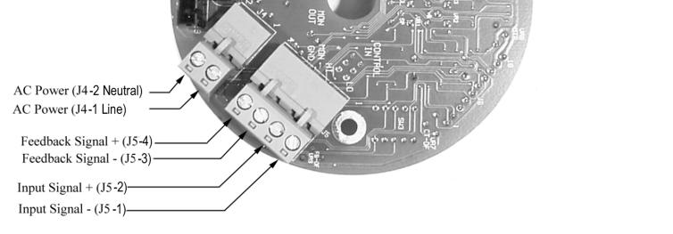
20 2.7 ELECTRICAL CONNECTIONS The electrical connections for the ECC are input signal, feedback output signal, and input power. Terminal blocks, with removable connectors are located on the bottom of the circuit board under the ECC cover. Conduit access to the ECC is via two threaded /2-4 inch NPT threaded openings in the ECC base. The Milton Roy ECC is commonly shipped with red ½ - 4 inch NPT plastic plugs in the conduit access openings. During installation, remove these shipping plugs and do not use them. Use appropriate cable glands instead. For IECEx installations, use an explosionproof conduit seal applied by the installer or user of the equipment according to code. All wiring should conform to National Electrical codes or local codes as they apply. Conduit bushings must be chosen to provide NEMA 4, and explosion proof integrity. In North America, use NEMA type 4 and/or explosion proof conduit fittings. In Europe, cable glands with IP66 and/or Ex d ratings are readily available with /2-4 inch NPT threads. WARNING ALWAYS DISCONNECT PRIMARY POWER BEFORE REMOVING THE COVER FROM THE ECC. FAILURE TO FOLLOW THESE INSTRUCTIONS COULD RESULT IN DEATH OR SERIOUS INJURY. CAUTION AVOID DAMAGE TO SENSITIVE ELECTRONICS, REMOVE THE COVER FROM THE ECC CAREFULLY 2.7. Installation of Input/Output Command Signal Wiring CAUTION IMPROPER CONNECTION OF THE COMMAND LINES CAN CAUSE DAMAGE TO THE ECC. USE ONLY 300 VOLT, 05 C RATED WIRE, MINIMUM 22 AWG, MAXUMUM 4 AWG. 3. Maintain integrity of safety approvals using only 300 volt, 05 C (UL 23 or equiv.) rated insulation. Maintain CE immunity ratings, using shielded cable inside of conduit. 4. Feed four (4 to 22 AWG) shielded wires through appropriately rated conduit bushing inserted into one of the conduit holes in base of ECC. Ground shields for four wires to a good chassis ground at control end. 5. Route wires to ECC keeping electrical interference to a minimum. Carefully pull four-position connector J5 from circuit board. Connect command signal wires to connector J5 (Figure 4 and 2). Reconnect connector J5 to circuit board Input Signal The input signal, used to control the ECC, can be either 4-20 ma or (-5 VDC). A five-position Dip switch, SW2 (Figure, located on the top of the circuit board) selects the control signal used by the operator. The factory sets SW2 for the model ordered and should not need changed. Position (Table 0) of SW2 sets the input signal. Position 2 sets the movement of the ECC after unintentional loss of the control signal. Position 3 and 4 sets the ECC for use with a pump or valve and should always be set to 3-OFF and 4-ON for the pump mode. Position 5 is not used.. To remove the cover: explosion proof units have a set screw in the base that locks the cover when it is closed and maintains its explosion proof rating. To remove the cover, first loosen the set screw in the base using a 5/64 hex key. 2. Unscrew the ECC cover by turning it counterclockwise (as viewed from the top). Lift the cover straight off and away. 0
 and COMMON (J5-3).")
21 2.7.3 Feedback Output Signal A position output, proportional to ECC position, is used for remote position indication. A current of 4-20 ma or a voltage of -5 VDC is available between MONITOR (J5-4) and COMMON (J5-3). Feedback zero and feedback span adjustments (Figure ) are provided to fine tune the output (see calibration instructions). DIP switch SW3 (Figure ) selects the feedback output signal. Use of the output signal is optional Feedback Output Signal 4-20 MA NOTE Do not connect the 4-20 ma output to a circuit with greater than a 500 ohm load. Set SW3 per Table for a 4-20 ma feedback signal Feedback Output Signal -5 VDC Figure 5. Circuit Board Connectors J4 and J5 Table 0. SW2 DIP Switch Settings INPUT SWITCH POSITION NOTE Do not connect the -5 VDC output to a circuit having less than 250 ohms impedance. Input Signal of 4-20 ma Input Signal of -5 VDC Hold Position on Loss of Control Signal Return to Lower Limit on Loss of Control Signal Pump Mode (limits absolute) Valve Mode (limits floating) Not Used ON OFF ON OFF OFF ON ON OFF NC Set SE3 per Table for a -5 VDC feedback signal. Table. SW3 DIP Switch Settings OUTPUT Output Signal of 4-20 ma Output Signal of -5 VDC SWITCH POSITION ON ON OFF OFF OFF OFF OFF ON ON ON
22 Installation of Primary Power Wiring Primary power wiring to operate the ECC should be routed via an on/off switch (there are no switches on the ECC) or a panel breaker switch.. Maintain integrity of safety approvals using only 300 volt, 05 C (UL 23 or equiv.) rated insulation. CAUTION Table 2. SW Voltage Selector Switch Setting For Input Power of 5VAC 50/60Hz Note: The motor and motor run capacitor must be rated for 5VAC operation, or damage will result. For Input Power of 230VAC 50/60Hz Note: The motor and motor run capacitor must be rated for 230VAC operation, or damage will result IMPROPER CONNECTION OF THE POWER LINE OR INCORRECT SUPPLY VOLTAGE CAN CAUSE DAMAGE TO THE ECC. DISCONNECT ALL POWER BEFORE CONNECTING WIRES. 2. Feed three (2 to 6 AWG) primary power wires through appropriately rated conduit bushing inserted into the other conduit hole in the base of the ECC. Connect ground wire to screw at ECC end. WARNING PROPERLY GROUND THE UNIT. 3. Carefully pull two-position connector J4 from circuit board (Figure 4). Connect HI-blk and LO-wht wires to terminal block connector J4 (Figure 2). Reconnect connector J4 to circuit board. CAUTION VOLTAGE SELECTOR SWITCH SW LOCATED ON TOP OF THE CIRCUIT BOARD MUST BE SET TO THE VOLTAGE LISTED ON YOUR DATA PLATE (FIGURE OR 2), OR DAMAGE TO MOTOR WILL RESULT. Voltage selector switch SW (Figure ), located on top of the circuit board, is a twoposition switch used to configure the ECC for an input of 5 VAC or 230 VAC. Insure SW is set to the voltage listed on your data plate (Figure or 2), attached to the enclosure. The factory sets SW for the model ordered and should not be changed. If the operating voltage must be changed, contact the Milton Roy factory at (25) for conversion parts and instructions. 2.8 CIRCUIT BOARD RETROFIT KIT INSTALLATION (Table 9) 2.8. Remove Old Circuit Board. Unscrew ECC cover by turning it counterclockwise (as viewed from the top). Lift cover straight off and away. 2. If the board you are replacing has terminal blocks for primary and signal wires, loosen screws and remove wires. Label wires before removal to facilitate re-installation. 3. If the old board has plug-in connectors, simply unplug all connectors from circuit board. 4. Remove circuit board from its three mounting standoffs Required Modifications Identify old circuit board type (see Figure 5 and 6) and follow directions specific to board. ECC Part Number (Figure 5). No adaptation needed. Motor plug is the same, and the run capacitor will plug directly into the new circuit board. Discard the old cup style safety cover. Proceed to paragraph 2.7.3, Install New Circuit Board. 2
23 ECC Part Number XXX and 05295XXX (Figure 6). Adapter for the motor plug is required, (Milton Roy p/n , a 5 pin male to 9 pin female connector). 2. Appropriate motor run capacitor is required since these boards had capacitor soldered to circuit board. 3. Motor run resistor if used, may need to be re-located on the base plate (Figure 7) to allow room to locate the motor run capacitor. 4. The motor run capacitor should be mounted using a new base plate mounting screw, p/n (6-32 x 7/6 ). CAUTION Install New Circuit Board. Connect: J J2 J3 J4 J5 9-pin motor connector, use adapter as required. 3-pin potentiometer connection. 4-pin motor run capacitor connection. 2-pin AC power connector. 4-pin control signal connector 2. Mount the board on the standoffs utilizing three captive 8-32 screws. Orient circuit board with voltage selector switch over feedback potentiometer (Figure 7). 3. Calibrate as required Section 4, Maintenance. VOLTAGE SELECTOR SWITCH SW LOCATED ON TOP OF THE CIRCUIT BOARD MUST BE SET TO THE VOLTAGE LISTED ON YOUR DATA PLATE (FIGURE OR 2), OR DAMAGE TO MOTOR WILL RESULT. 5. Voltage selector switch SW (Figure ), located on top of the circuit board, is a twoposition switch used to configure the ECC for an input of 5 VAC or 230 VAC. Insure SW is set to the voltage listed on your data plate (Figure or 2), attached to the enclosure. The factory sets SW for the model ordered and should not be changed. If the operating voltage must be changed, contact the Milton Roy factory at (25) for conversion parts and instructions. 6. Set DIP switch SW2 (Paragraph 2.6.2, Input Signal). 7. Set DIP switch SW3 for 4-20 ma or (-5 VDC) output appropriately. (Paragraph 2.6.3, Feedback Output Signal). 8. Proceed to paragraph Install New Circuit Board. 3


24 Figure 6. Circuit Board, Figure 7. Circuit Board, XXX, 05295XXX 4


25 Figure 8. Conversion Detail 5
 and signal LO (-) must be connected correctly or the ECC will not respond. (Installation, Section 2) 2. Apply a command signal.")
26 SECTION 3 OPERATION 3. CONTROLS The Milton Roy ECC is equipped with a hand wheel that can be used to reposition the ECC shaft. The hand wheel can only be used when the primary power is off. 3.2 INITIAL START-UP Fill the pump with oil and prepare the pump for operation according to procedures in the instruction manual for the pump.. Check signal connections. The signal HI (+) and signal LO (-) must be connected correctly or the ECC will not respond. (Installation, Section 2) 2. Apply a command signal. CAUTION VOLTAGE SELECTOR SWITCH SW LOCATED ON TOP OF THE CIRCUIT BOARD MUST BE SET TO THE VOLTAGE LISTED ON YOUR DATA PLATE (FIGURES OR 2), OR DAMAGE TO MOTOR WILL RESULT. 3. Apply AC power. 4. Slowly change the command signal from one extreme to the other. The pump capacity knob should move from 0% to 00% and back to 0%. 5. If the unit performed properly, confirm that all connections have been made properly, install the cover on the ECC. Torque the cover to 5 lb-ft (20 N-m). For explosion proof units, tighten set screw in base using a 5/64 hex key to lock the cover and prevent tampering while in operation. Install unit in service. (If the pump moved but did not have the proper travel, the ECC may need to be adjusted. See ECC Calibration, Section Operating Modes The Milton Roy ECC can be set for one of two modes of operation. The operating mode must be established before the control signal can be set up. The ECC is factory configured for directacting, 4-20 ma command signal range, which is the most common. The model number, found on the data plate, determines the mode set by the factory. The two modes are described below:. Direct-acting - an increasing control signal drives the pump to 00% capacity. 2. Reverse-acting - an increasing control signal drives the pump to 0% capacity. Perform the following procedure to change the operating mode:. Apply power and drive ECC and capacity control knob to 00% capacity setting by applying a 20 ma command signal. 2. Remove power from ECC and remove cover. 3. Install jumper plugs between circuit board and potentiometer and circuit board and motor (Figure 8). Jumper plugs are available from the factory: 3 wire jumper (J2) 5 wire jumper (J) Figure 9. Jumper Plugs/Action Mode Conversion. 6
27 4. Disconnect ECC from pump. Remove the four screws that mount the ECC to the bracket and carefully remove the ECC from the pump. On MaxRoy B pumps loosen coupling nut (Figure 9, Item 865) and coupling (860) to allow free rotation of ECC shaft. 5. Apply power to ECC and allow it to run to its new position at a zero ma signal. Ensure the capacity control knob did not rotate. 6. Apply a 4 ma signal to place ECC in reverse-acting mode. This is now the 00% capacity setting. 7. With ECC and pump capacity knob at 00% capacity setting, carefully slide the ECC shaft back into the coupling and replace the four mounting screws. If required, rotate the pump adjustment screw to allow assembly. Do not move the ECC shaft. On MaxRoy B pumps tighten coupling nut (Figure 9, Item 865) and coupling (860) (Approximately 40 lb. ft.). Pin should remain in approximate midpoint of slot in coupling. 8. Check operation through full signal range and recalibrate if required (See ECC Calibration, Section 4) Input Signal The ECC is shipped from the factory adjusted to accept a 4-20 ma command signal. If the unit is to be operated with any other range, it must be set up for that range. Adjusting the span control, VR, Figure, determines the maximum travel of the ECC over the full range of the command signal. Adjusting the zero control, VR2, Figure shifts the position of this travel (Figure 9). The ECC may be set up to operate over a split range of either 0 to 00% capacity corresponding to a 2 to 20 ma signal, or 0 to 00% capacity corresponding to a 2 to 4 ma signal (in reverse action mode) - such as pumps A & B in a typical ph control system, shown in Figure 0. Figure 0. Effect of Zero & Span Controls Figure. Split Range Operation with Two Pumps (Typical ph Control System). 3.3 CONTROL RANGE ADJUSTMENT First remove the cover from the ECC. On the ECC circuit board, Figure, are four lights and four small trim potentiometers. The lights are in pairs. The pots are for zero, span, upper limit, and lower limit adjust. CAUTION THE LIMIT POTENTIOMETERS MUST BE SET BEFORE CHANGING THE CONTROL RANGE. THEY MUST BE ADJUSTED (AS THEY ARE AT THE FACTORY) TO PREVENT OVERTRAVEL OF THE CONTROL SPOOL. IMPROPER ADJUSTMENT OF THESE UPPER AND LOWER LIMIT TRIM POTS MAY RESULT IN DAMAGE TO THE PUMP OR THE ECC.. Energize the ECC with AC power. 2. Make sure that the appropriate jumper plugs have already been either removed or installed to establish the desired mode of action (direct action or reverse action) as described earlier in this section. 7
28 3. Locate the Zero (VR2) and Span (VR) adjust controls on the printed circuit board (PCB) shown in Figure. 4. Apply the lower limit input signal to the unit. For a 4-20 ma operating range, this signal will be 4 ma; (for a 2-20 ma range, the lower signal will be 2 ma). 5. Turn the Zero (VR2) adjust control until the pump capacity indicator ring moves to the desired point or until no further adjustment is possible, whichever comes first. 6. Apply the upper limit input signal to the unit (this will be 20 ma). 7. Turn the Span (VR) adjust control until the pump capacity control knob moves to the desired point. 8. Repeat Steps 4 through 7 until the desired results are achieved. 8


29 Figure 2. Circuit Board, Top. Figure 3. Circuit Board, Bottom. 9
30 SECTION 4 MAINTENANCE 4. SPARE PARTS NOTE To avoid delays in repairs, the following spare parts should be stocked for your ECC: Federal law prohibits handling of equipment that is not accompanied by an OSHA Material Safety Data Sheet (MSDS). A completed MSDS must be packed in the shipping crate if the ECC is returned attached to a pump. These safety precautions will aid the troubleshooting and repair procedure and preclude serious injury to repair personnel from hazardous residue in pump liquid end. NOTE See Paragraph 2..2 and 2..3 before ordering circuit boards. Circuit Board: 30300/39320 NOTE All inquiries or parts orders should be addressed to your local Milton Roy representative or send to: When ordering Potentiometer Assembly or Motor, also order jumper wires. Jumper wires are used when older wiring does not match the color coding of the new parts. 3 wire jumper: Nylon Worm Gear: Motor: 5 wire jumper: Parts Department Milton Roy Company Flow Control Division 20 Ivyland Road Ivyland, PA Phone: (25) Fax: (25) Call Factory Call Factory MAINTENANCE Parts orders must include the following information: Because of its solid-state design, the Milton Roy ECC is exceptionally reliable and should seldom need maintenance or repair. Aside from calibrations (the unit is calibrated at the factory and should not need calibrated initially), the only typical maintenance procedures are replacement of the printed circuit board, feedback potentiometer, nylon worm gear, and/or replacement of the motor. Pump serial number (on pump nameplate) Model number (on ECC nameplate) Part description Quantity required Always include the serial and model numbers in all correspondence regarding the unit. 4.2 RETURNING UNITS TO THE FACTORY Electronic Capacity Control (ECC) units will not be accepted for repair without a Return Material Authorization, available from the Factory Repair Department. If the ECC is being returned attached to a pump, process liquid should be flushed from the pump liquid end and oil should be drained from the pump housing before the pump is shipped. Label the unit clearly to indicate the liquid being pumped. 20
31 4.4 PRINTED CIRCUIT BOARD (PCB) REPLACEMENT 4.4. Removal of PCB (Figure 5). Apply power and set pump stroke adjust knob to 0% setting or remove power and manually turn the pump stroke adjust knob to 0% setting. WARNING FIGURE 4. Circuit Board Removed. ALWAYS DISCONNECT ELECTRICAL POWER FROM THE PUMP MOTOR AND ECC BEFORE PERFORMING ANY MAINTENANCE. FAILURE TO FOLLOW THESE INSTRUCTIONS COULD RESULT IN DEATH OR SERIOUS INJURY. 4.5 FEEDBACK POTENTIOMETER REPLACEMENT 4.5. Removal of Feedback Potentiometer. Apply power and set pump stroke adjust knob to 0% setting or remove power and manually turn the pump stroke adjust knob to 0% setting. 2. Disconnect electrical power to ECC. 3. Disconnect ECC from its mounting bracket by removing four mounting screws and pulling unit. WARNING ALWAYS DISCONNECT ELECTRICAL POWER FROM THE PUMP MOTOR AND ECC BEFORE PERFORMING ANY MAINTENANCE. FAILURE TO FOLLOW THESE INSTRUCTIONS COULD RESULT IN DEATH OR SERIOUS INJURY. 4. Unscrew cover (280) from ECC. 5. Carefully loosen three captive screws equally (do not completely remove screws) and gently lift PCB from mounting standoffs. 6. Disconnect connectors J, J2, J3, J4, and J5 from bottom of PCB. 2. Disconnect electrical power to ECC Installation of PCB 3. Remove PCB (Paragraph 4.4.).. Connect connectors J, J2, J3, J4, and J5 to bottom of PCB. 4. Remove two screws that secure potentiometer/bracket/gear assembly. Remove feedback potentiometer. 2. Place PCB on three standoffs and carefully tighten captive screws. Ensure nylon washers are on captive screws between PCB and standoffs Installation of Feedback Potentiometer. Install replacement potentiometer assembly. Apply very slight pressure and align teeth of gear to lay inside groves of nylon gear. Do not force gears together overly tight or allow teeth to lay on top of worm gear teeth. Tighten two retaining screws. There should be slight pressure between gears. 3. Perform calibration B if board was calibrated at factory or calibration C if board was not calibrated at factory. 2. Apply a very small amount of lithium grease (if needed to motor shaft nylon worm gear. Motor shaft may have grease from previous maintenance. 2
32 4.6.2 Installation of Nylon Worm Gear 3. Compare wire colors of new feedback potentiometer connector to wire colors of old feedback potentiometer connector. When place-ment of wires is different install jumper cable (ordered with new feedback potentiometer) between P2 and J2 (Figure 3).. Slide new nylon worm gear (90) over motor shaft and align shaft holes to gear holes with 3/32 punch. Being careful not to damage nylon worm gear, press spring pin (200) through holes in gear and shaft. Place pin equal distance from both sides of gear. 4. Install PCB (Paragraph 4.4.2). WARNING 5. Perform calibration A. ALWAYS DISCONNECT ELECTRICAL POWER FROM THE PUMP MOTOR AND ECC BEFORE PERFORMING ANY MAINTENANCE. FAILURE TO FOLLOW THESE INSTRUCTIONS COULD RESULT IN DEATH OR SERIOUS INJURY. 4.6 NYLON WORM GEAR REPLACEMENT 4.6. Removal of Nylon Worm Gear. Apply power and set pump stroke adjust knob to 0% setting or remove power and manually turn the pump stroke adjust knob to 0% setting. 2. Reinstall capacitor (65) (if removed). Tighten screw. Do not allow wires to be pinched under capacitor. WARNING 3. ALWAYS DISCONNECT ELECTRICAL POWER FROM THE PUMP MOTOR AND ECC BEFORE PERFORMING ANY MAINTENANCE. FAILURE TO FOLLOW THESE INSTRUCTIONS COULD RESULT IN DEATH OR SERIOUS INJURY. Install feedback potentiometer (Paragraph 4.5.2). 4. Install PCB (Paragraph 4.4.2). 5. Perform calibration A. 4.7 MOTOR REPLACEMENT 2. Disconnect power from ECC REMOVAL OF MOTOR 3. Remove PCB (Paragraph 4.4.).. Apply power and set pump stroke adjust knob to 0% setting or remove power and manually turn the pump stroke adjust knob to 0% setting. 4. Remove feedback potentiometer (Paragraph 4.5.). 5. Remove screw that secures capacitor (65) (if installed) to ECC. Slide capacitor to one side away from nylon worm gear (90). Leave wires attached. 2. Disconnect power from ECC. 3. Disconnect ECC from pump. Remove four bolts/screws that mount ECC to bracket and carefully remove ECC from pump. 6. Using a 3/32 punch, push out spring pin holding nylon gear on shaft. Remove gear. 4. Disconnect gear box (mroy A and B has no gear box) from ECC. Remove four screws that mount gear box to ECC and carefully remove gear box from ECC. 5. Clean grease from gear located at bottom of motor shaft. Using a /8 punch push out spring pin holding gear and slide gear off shaft. Retain gear and spring pin. Parts will be used during installation of new motor. 22
33 6. On mroy A and B ECCs use a 3/6 punch and push out spring pin (Figure 6 and 7, item 920) holding drive shaft (90). Remove drive shaft. Retain drive shaft and spring pin. Parts will be used during installation of new motor. 7. Reposition feedback potentiometer (Paragraph 4.5.2, Steps & 2). 8. Position wiring to J as noted previously and attach two cable ties. 9. Install PCB (Paragraph 4.4.2, Steps and 2). 7. Remove PCB (Paragraph 4.4., Steps 4-6). 8. Loosen two screws for feedback potentiometer and slide potentiometer away from worm gear. 0. On mroy A and B ECCs slide drive shaft (Figure 6 and 7, item 90) over bottom of motor shaft and align mounting holes. Press spring pin (920) through both holes with 3/6 punch. Place pin equal distance from both sides of gear. 9. Note placement of wiring to J for identical placement during installation of new motor. Remove two cable ties from connector J wiring.. Slide gear removed previously from bottom of motor shaft over new motor shaft. Align shaft holes to gear holes. Being careful not to damage gear, press spring pin through holes in gear and shaft with /8 punch. Place pin equal distance from both sides of gear. 0. Carefully remove two screws (Figure 5, item 40) from adapter plate (60) and remove adapter plate from motor.. Remove motor wires from J. 2. Remove four mounting screws (50) from bottom of base (0) and remove motor. 2. Apply lithium grease to gear above and mount gear box to ECC with four screws (mroy A and B has no gear box) Installation of Motor 3. Mount ECC to pump. Connect ECC to pump bracket with four bolts/screws.. Mount motor to base (0) and secure with four mounting screws (50). 4. Connect power to ECC. 2. Connect motor wires to J. 5. Perform calibration A. 3. Remove worm gear (90) from old motor. Carefully remove spring pin (200) with 3/32 punch without damage to worm gear (90). 4. Slide worm gear (90) over new motor shaft and align shaft holes to gear holes. Being careful not to damage nylon worm gear, press spring pin (200) through holes in gear and shaft with 3/32 punch. Place pin equal distance from both sides of gear. 5. Attach adapter plate (60) to motor and secure with two screws (40). One screw (40) also mounts capacitor (65) to adapter plate. 6. Apply a very small amount of lithium grease (if needed) to motor shaft nylon worm gear. Motor shaft may have grease from previous maintenance. 23
34 4.8 ECC CALIBRATION Calibration A Calibration A is performed to synchronize the ECC with the pump. Calibration A is performed when: WARNING YOU WILL BE MAKING ADJUSTMENTS TO THE ECC CONTROL CIRCUIT BOARD WHILE IT IS POWERED UP. THIS CONTROL BOARD IS POWERED BY POTENTIALLY DANGEROUS VOLTAGE (5 OR 230 VAC). THE CALIBRATION PROCEDURE IS TO BE PERFORMED ONLY BY QUALIFIED PERSONNEL FAMILIAR WITH THE HAZARDS INHERENT WORKING NEAR HIGH VOLTAGES. MILTON ROY ASSUMES NO RESPONSIBILITIES FOR DAMAGE TO EQUIPMENT OR INJURY TO PERSONNEL WHILE PERFORMING THIS CALIBRATION PROCEUDRE. Replacing any components in the position feedback assembly. This includes the nylon worm gear/driver, the potentiometer, and/or potentiometer gear. Adding or removing reverse action jumpers (section 3).. Tools needed for calibration A: a) Digital volt meter (DVM) or equivalent with resistance, 5 VDC, and 20 ma. NOTE b) 4-20 ma (-5 VDC) source and 5 or 220 VAC source ECCs are calibrated at the factory and usually do not need to be calibrated initially. c) Precision screwdriver to adjust potentiometers 4.8. Calibration Routines d) Tool kit The Milton Roy ECC has nine adjustment potentiometers. These potentiometers adjust the ECC's span and zero travel, lower and upper travel limits, feedback zero, feedback span, control offset, range offset, and feedback offset. Control offset, range offset, and feedback offset will only be adjusted during a complete calibration procedure (calibration C). These three adjustments are usually not changed. 2. Preparation: a) All new components should be replaced. b) Insure pump is set to 0% setting. c) Remove AC power. d) Loosen set screw (530) in base, remove cover (280) from ECC. Before calibration is performed set-up the voltage selector switch, SW(Paragraph 2.6.4), input signal SW2(Paragraph 2.6.2), and feedback output signal SW3(Paragraph 2.6.3). Use of the feedback output signal is optional and needs set only if it will be used. CAUTION VOLTAGE SELECTOR SWITCH SW LOCATED ON TOP OF THE CIRCUIT BOARD MUST BE SET TO THE VOLTAGE LISTED ON YOUR DATA PLATE (FIGURES OR 2), OR DAMAGE TO MOTOR WILL RESULT. There are three levels of calibration that can be performed. Use the appropriate calibration routine for your requirement. For all routines, reference Figure 0. e) Ensure voltage selector switch is set to 5 VAC or 230VAC as indicated on data plate (Section 2). f) 24 If circuit board has been replaced ensure DIP switches SW2 and SW3 are set as needed for proper orientation (Section 2).

35 g) Remove ECC from Pump. WARNING 3. Remove PCB (Paragraph 4.4.) to gain access to feedback potentiometer. USE EXTREME CAUTION. FULL LINE VOLTAGES ARE PRESENT ON AREAS OF THE CIRCUIT BOARD. 4. Remove P2 and connect DVM between P2 pin and P2 pin 2 (Figure 4). Loosen screws to potentiometer to allow movement of potentiometer gear without moving nylon worm gear. Set potentiometer to.5k ohms ±00 ohms for Milroyal B, C, and Macroys, 0.87 ohms ±0. ohms for mroys and.3 ohms ±0. ohms for Maxroys and Milroyal D ECCs and re-tighten potentiometer screws. This sets the resistance of the potentiometer. 7. Apply AC power to ECC. 8. Apply a 4 ma ( VDC) control signal and allow motor to run until it stops. Disconnect power. 9. Manually turn pump stroke adjust to a position of 0% for direct-acting or 00% for reverse-acting. 0. Install ECC to pump. Do not rotate ECC shaft. If necessary, slightly rotate pump coupling for proper engagement with ECC drive pin. Install and tighten mounting bolts.. Using a screwdriver, rotate motor shaft to turn pump stroke adjust to minus % (this is percent below 0% reading, shows as 9 on most pump micrometer rings). (Max Roy pump has mechanical stops). 2. Low signal adjust: Disconnect motor lead, J. Apply a 4 ma ( VDC) signal and adjust zero pot (VR2) until both motion lights are off (CR5 and CR6). Adjust lower limit LED (CR3) until just on using (VR3), if needed. Adjust feedback zero pot (VR5) to 4 ma ( VDC), if needed. Figure 5. Potentiometer Connector P2 Pins and 2 NOTE The MaxRoy B, Milroyal B, C, G, MacRoy G, and D uses a 20: gearbox. It requires 200 turns at the actuator handwheel to adjust the pump stroke 0 turns (0% to 00%). The Milroyal D uses a 5: or 2 :. 5. Install PCB (Paragraph 4.4.2) and perform remaining adjustments. WARNING 3. Manually turn pump stroke adjust to a position of 00% (0%) for direct-acting or 0% (-%) for reverse-acting. (The Max Roy pump has mechanical stops.) USE EXTREME CAUTION. FULL LINE VOLTAGES ARE PRESENT ON AREAS OF THE CIRCUIT BOARD. 6. Disconnect J5 (Figure 4 and connect a 4-20 ma current source (or -5 VDC) to input signal (high and low) connection at fourposition connector located under PCB. 4. High signal adjust: Apply 20 ma (5 VDC) signal and adjust span pot (VR) until both motion lights are off. Adjust upper limit LED (CR4) until just on (VR4), if needed. Adjust feedback span pot (VR6) to 20 ma (5 VDC), if needed. 25
36 5. Verify: Verify travel with low and high signal. Readjust feedback zero and feedback span if needed for travel. Readjust limits until limit LEDs are just on, if needed. f) WARNING USE EXTREME CAUTION. FULL LINE VOLTAGES ARE PRESENT ON AREAS OF THE CIRCUIT BOARD. 6. Disconnect input and output control signal wiring, reconnect all connectors, and install ECC cover. 3. Disconnect J5 (Figure 4) and connect a 4-20 ma current source (or -5 VDC) to input signal (high and low) connection at fourposition connector located under PCB Calibration B Calibration B is performed to synchronize the ECC with the pump. Remove ECC from pump. WARNING Calibration B is performed after replacing the circuit board with a new board that has been factory calibrated. USE EXTREME CAUTION. FULL LINE VOLTAGES ARE PRESENT ON AREAS OF THE CIRCUIT BOARD.. Tools needed for calibration B: 4. Apply AC power to ECC. a) Digital volt meter (DVM) or equivalent with resistance, 5 VDC, and 20 ma. 5. Apply a 4 ma ( VDC) control signal and allow motor to run until it stops. Disconnect power. b) 4-20 ma (-5 VDC) source and 5 or 220 VAC source 6. Manually turn pump stroke adjust to a position of 0% for direct-acting or 00% for reverse-acting. c) Precision screwdriver to adjust potentiometers d) Tool kit Install ECC to pump. Do not rotate ECC shaft. If necessary, slightly rotate pump coupling for proper engagement with ECC drive pin. Install and tighten mounting bolts. Preparation: a) Ensure new circuit board is replaced. 8. Using a screwdriver, rotate motor shaft to turn pump stroke adjust to minus % (this is percent below 0% reading, shows as 9 on most pump micrometer rings). (Max Roy pump has mechanical stops). b) Remove AC power. c) Remove cover from ECC. CAUTION 9. Low signal adjust: Disconnect motor lead, J. Apply a 4 ma ( VDC) signal and adjust zero pot (VR2) until both motion lights are off (CR5 and CR6). Adjust lower limit LED (CR3) until just on (VR3), if needed. Adjust feedback zero pot (VR5) to 4 ma ( VDC), if needed. VOLTAGE SELECTOR SWITCH SW LOCATED ON TOP OF THE CIRCUIT BOARD MUST BE SET TO THE VOLTAGE LISTED ON YOUR DATA PLATE (FIGURES OR 2), OR DAMAGE TO MOTOR WILL RESULT. d) Ensure voltage selector switch is set to 5 VAC or 230 VAC as indicated on data plate (Section 2). NOTE The MaxRoy B, Milroyal B, C, G, MacRoy G, and D uses a 20: gearbox. It requires 200 turns at the actuator handwheel to adjust the pump stroke 0 turns (0% to 00%). The Milroyal D uses a 5: or 2 :. e) If new circuit board has been replaced ensure DIP switches SW2 and SW3 are set as needed for proper operation (Section 2). 26
37 0. Manually turn pump stroke adjust to a position of 00% (0%) for direct-acting or 0% (-%) for reverse-acting. (The Max Roy pump has mechanical stops). c) Loosen set screw (530) in base, remove cover (280) from ECC. CAUTION. High signal adjust: Apply 20 ma (5 VDC) signal and adjust span pot (VR) until both motion lights are off. Adjust upper limit LED (CR4) until just on (VR4), if needed. Adjust feedback span pot (VR6) to 20 ma (5 VDC), if needed. VOLTAGE SELECTOR SWITCH SW LOCATED ON TOP OF THE CIRCUIT BOARD MUST BE SET TO THE VOLTAGE LISTED ON YOUR DATA PLATE (FIGURE OR 2), OR DAMAGE TO MOTOR WILL RESULT. 2. Verify: Verify travel with low and high signal. Readjust feedback zero and feedback span if needed for travel. Readjust limits until limit LEDs are just on, if needed. d) Ensure voltage selector switch is set to 5 VAC or 230VAC as indicated on data plate (Section 2). e) Ensure DIP switches SW2 and SW3 are set as needed for proper operation (Section 2). 3. Disconnect input and output control signal wiring, reconnect all connectors and install ECC cover. f) Calibration C Remove ECC from pump. NOTE Calibration C is a complete calibration. Performed after replacing a circuit board with a new board that was not factory calibrated. For example, A user may want to move an ECC from a mroy series of pumps to a Milroyal B series. This procedure would be used to now set up the Milroyal B ECC. It is important for the user to understand that circuit boards obtained from the manufacturer are preset for a specific series of pumps. This procedure can also be used as a diagnostic tool to verify the integrity of a circuit board. Only qualified personnel familiar with the complete calibration procedure should use it as a diagnostic tool. Table 3 lists the resistances value of VR8 that is set at the manufacturer on circuitcard 30300/39320 when the series (pump) it is being used on is specified. Table 3. Circuit Board Resistance Values. Tools needed for calibration C: a) Digital volt meter (DVM) or equivalent with resistance, 5 VDC, and 20 ma. b) 4-20 ma (-5 VDC) source and 5 or 220 VAC source PRODUCT SERIES Resistance Value ohms, adjust VR8 to get All Value ECCs,450 to,550 All mroy Pumps,450 to,550 Milroyal B, C, & G 9,800 to 0,800 Milroyal D 8,600 to 8,700 MacRoy G 9,800 to 0,800 maxroy B 9,800 to 0,800 NOTE c) Precision screwdriver to adjust potentiometers Values above must be obtained with feedback potentiometer connector J2 unplugged. Replace J2 after resistance is set. d) Tool kit 2. Preparation: g) Disconnect feedback potentiometer connector J2. a) Ensure circuit board has been replaced. b) Remove AC power. 27
38 h) Connect a DVM across test pins J6-9 and J6-0 located on top of PCB (Figure ). Adjust range offset (VR8) for the value of your product, see Table 3 (VR8 may not need adjusted). i) full CW and complete paragraph step 2. a through 3. h. 4. Adjustments for span (VR) and feedback span (VR6). Connect feedback potentiometer connector J2. a) Disconnect motor lead, J. Apply 20 ma (5 VDC) input signal. Reset DVM for VDC range. 3. Initial adjustments for zero (VR2), control offset (VR7), feedback offset (VR9), and feedback zero (VR5) (Figure ). (ECC may be on or off the pump.) b) Measure J6-. Manually move ECC motor shaft to adjust feedback pot for +5 VDC. c) Adjust span pot (VR) until both motion LEDs (CR5 and CR6) are off. WARNING USE EXTREME CAUTION. FULL LINE VOLTAGES ARE PRESENT ON AREAS OF THE CIRCUIT BOARD. d) Measure J6-6. Adjust feedback span (VR6) for - 4 VDC. a) Disconnect motor lead, J. Apply 4 ma ( VDC) input signal. Apply 5 or 230 VAC power. 5. Reconnect P and apply power. Vary input signal from low to high and observe correct operation. b) Attach negative lead of DVM to pin 8 of test connector J6. 6. Apply a 4 ma ( VDC) control signal and allow motor to run until it stops. Disconnect power. c) Measure J6-. Manually move ECC motor shaft to adjust feedback pot for + VDC ± 0. VDC (carefully use large screwdriver through center hole in circuit board to manually turn motor shaft). 7. Manually turn pump stroke adjust to a position of 0% for direct-acting or 00% for reverse-acting. 8. Install ECC to pump. Do not rotate ECC shaft. If necessary, slightly rotate pump coupling for proper engagement with ECC drive pin. Install and tighten mounting bolts. d) Measure J6-2. Adjust zero pot (VR2) for - VDC ± 0.05 VDC. e) Measure J6-4. Adjust control-offset pot (VR7) for - VDC ± 0.05 VDC. f) 9. Using a screwdriver, rotate motor shaft to turn pump stroke adjust to minus % (this is percent below 0% reading, shows as 9 on most pump micrometer rings). (Max Roy pump has mechanical stops). Measure J6-3. Should read 0.00 VDC or close to it. g) Measure J6-6. Adjust feedback offset (VR9) for 0.00 VDC ±0. VDC. 0. Low signal adjust: Disconnect motor lead, J. Apply a 4 ma ( VDC) signal and adjust zero pot (VR2) until both motion lights are off (CR5 and CR6). Adjust lower limit LED (CR3) until just on (VR3), if needed. Adjust feedback zero pot (VR5) to 4 ma ( VDC), if needed. h) Measure J6-7 with DVM set to ma range (VDC range for -5 VDC output). Adjust feedback zero (VR5) for 4 ma ±0.mA ( VDC ±0. VDC). i) If any Initial adjustments for zero (VR2), control offset (VR7), feedback offset (VR9), or feedback zero (VR5) can not be attained set VR3 full CCW and VR4 NOTE The MaxRoy B, Milroyal B, C, G, MacRoy G, and D uses a 20: gearbox. It requires 200 turns at the actuator handwheel to adjust the pump 28
39 stroke 0 turns (0% to 00%). The Milroyal D uses a 5: or 2:.. Manually turn pump stroke adjust to a position of 00% (0%) for direct-acting or 0% (-%) for reverse-acting. (Max Roy pump has mechanical stops.) 2. High signal adjust: Apply 20 ma (5 VDC) signal and adjust span pot (VR) until both motion lights are off. Adjust upper limit LED (CR4) until just on (VR4), if needed. Adjust feedback span pot (VR6) to ma (5 VDC), if needed. 3. Verify: Verify travel with low and high signal. Readjust feedback zero and feedback span if needed for travel. Readjust limits until limit LEDs are just on, if needed. 4. Disconnect input and output control signal wiring, reconnect all connectors, and install ECC cover. 29
40 SECTION 5 TROUBLE SHOOTING ECC moves to same position regardless of signal applied Limit lights flicker as ECC moves ECC does not respond to 4-20 ma command signal Improper command signal applied to ECC. Connect ma meter into signal line. Read signal. If necessary, correct signal source, possible broken wire, loose connection, etc. Mode setup incorrect. Review initial start-up procedure. Feedback potentiometer gear slipping or worn. Manually move knob, apply control signal, and observe gear. If necessary, replace feedback potentiometer assembly. Bad feedback potentiometer. With oscilloscope, observe pot signal while in motion. If necessary, replace feedback potentiometer assembly. Bad connection at plugs. Check continuity. Repair or replace plugs and/or wiring as necessary. Bad printed circuit board. Replace PC board. No power to ECC. Correct by applying AC power to ECC. Polarity of 4-20 ma signal wires connected to terminals may be backwards. Check polarity and correct if improper. Motor frozen in place. With power off, use handwheel to check motor rotation. Replace motor if necessary. Potentiometer bad. Replace potentiometer. Bad printed circuit board. Replace PC board. ECC will only travel in one direction Bad printed circuit board. Replace PC board. ECC chatters or vibrates ECC is driving the pump adjustment against the pump s mechanical stop. Reset the ECC and pump high and low limits per calibration procedure. If limits are okay, then circuit board and/or feedback potentiometer should be replaced. 30
41 THIS PAGE IS INTENTIONALLY BLANK 3
42 SECTION 6 PARTS LIST 6. GENERAL. This section gives information regarding replaceable components. 6.2 ILLUSTRATED PARTS LIST 5. Figure and Item Number Column a) The item numbers shown in the detailed parts list correspond to the item numbers appearing on the exploded view illustration. To find an unknown part number, locate the part on the illustration and note the item number. Look for the item number on the detailed parts list. The part number is on the same line. A dash (-) precedes nonillustrated item numbers. 6. Description Column a) The name of the item is in the description column. 7. Part Number Column a) The supplier s part number is listed in the part number column 8. Quantity Column a) The numbers appearing in the quantity column are the total quantity of the listed part required in its immediate assembly. 9. Reference Code Column a) This column is used to denote assembly and detail part variations among similar components (models) covered by this publication. When the symbol A, B, etc. is entered in this column, the part is used only in the model at which the symbol appears. If the column is blank, the part is used in all models. 32
43 Figure 6A. Electronic Capacity Control ( ). 33
44 Figure 6B. Section B-B with Set Screw 34


45 Figure 6C. Electronic Capacity Control ( ) 35
46 6.3 ELECTRONIC CAPACITY CONTROL PARTS LIST Model: MacRoy G & D mroy maxroy B Code: A B C Figure Item Number Number 5 Model: Milroyal B Milroyal C Milroyal D Milroyal G Code D E F G Description Part Number Quantity 0 Base (Explosion Proof) Bushing, Bronze A, B, C, D, F, G 20 Bushing E 30 Seal A, B, C, D, F, G A, C, D, F, G B E A, C, D, F, G B E inch Motor (5 VAC, 224M) Motor (5 VAC, 224N) Motor (5 VAC, P-400) Motor (220 VAC, 227D) Motor (220 VAC, 227E) Motor (220 VAC, P-400) Jumper, Reverse Acting Wire, BLU, 22 gauge, P-400 only Screw, No x /2 Ground Screw, Green, Explosion Proof Only Ground Lug, Explosion Proof Only Adapter Plate Shrink Tubing, / inch 62 Resistor, 200 ohms, 5VAC A, B, C, D, F, G 62 Resistor, 750 ohms, 220VAC A, B, C, D, F, G Wire, BLU, 22 gauge Wire, YEL, 22 gauge Capacitor UF inch 9 inch 65 Capacitor.5 UF Capacitor 3 UF Capacitor 4 UF Capacitor 5 UF Reference Code A, B, C, D, F, G B (220VAC) A, C, D, F, & G (220VAC) E (220VAC 60Hz) A, B, C, D, F, & G (5VAC), E (220VAC 50Hz) E (5VAC)
47 Figure Item Number Number Part Number Quantity inch 7 inch 3 3 E E F B, C A, D, E, G Mounting Base, Tie-Rap Tie-Rap Connector (P3), AMP, 4 Pin Wire, BRN Wire, ORN Washer, Spring Lock, No. 8 Circuit Board Standoff Potentiometer Assembly Includes Items 00, 0, 02, 03 (8 Teeth), 04, 05, 06, 07, 08, Pot. (0 Turns) Potentiometer Assembly Includes Items 00, 0, 02, 03 (32 Teeth), 04, 05, 06, 07, 08, Pot. ( Turn) Potentiometer Assembly Includes Items 00, 0, 02, 03 (32 Teeth), 04, 05, 06, 07, 08, Pot. (0 Turns), Bracket, Potentiometer Potentiometer Potentiometer Wire, BLK & WHT, 22 gauge Gear, 8 Teeth inch -03 Gear, 32 Teeth Wire, RED & WHT, 22 gauge Wire, GRY, 22 gauge Pin, Spring, x 3/8 Shrink Tubing, /8 Connector (P2), AMP, 3 Pin Washer, Plastic Washer, Spring Lock, No. 4 Screw, No x 3/6 Screw, No x 7/6 Washer, Lock, No. 6 Connector (P), AMP, 9 Pin Ties, Cable Identification Plate, Terminal Square Ring Seal inch 7 inch 3 inch Gear, Worm, Single Lead Description 37 Reference Code E E A, D, E, F, G B, C F A, B, C, D, E, G F A, B, C, D, E, G
48 Figure Item Number Number Part Number Description Quantity Reference Code Gear, Worm, Double Lead Pin, Spring, 3/32 x /2 Circuit Board (5 VAC, 230 VAC, 50/60 Hz), Specify Pump Circuit Board (5 VAC, 230 VAC, 50/60 Hz), Specify Pump F A, B, C, D, F, G 280 Cover, Short A, B, C, D, F, G Cover, Tall Bushing, Bronze E 300 Shaft, Hand Wheel A, B, C, D, F, G Shaft, Hand Wheel O-ring, x 0.070, BUNA Spring Clip, Retaining Knob, Hand Pin, Spring, 0.25 x -/4 Label, Explosion Label, NEMA 4 Shaft, Drive Coupling E -385 Pin, Spring, /8 x 5/ A, C, D, E, F, G Rivet Plug Gearbox(20:) Double Stage 2 2 A, C, D, G 40 Gearbox, Single (5:) F(Low Pressure) 40 Gearbox(2:) Double Stag CALL FACTORY CALL FACTORY F(High Pressure) Items not shown Connector (P4), 2 Position Phoenix Connector (P5), 4 Position Phoenix Set Screw, # E E
49 Figure 7. mroy A ECC Mounting Adapter (DWG ). 39
50 6.4 PARTS LIST FOR MROY ECC MOUNTING ADAPTER Model: mroy A Figure Number Item Number Items not shown. Description Kit, ECC Retrofit, RT, RH, & RJ Plunger, Includes Wrench Kit, ECC Retrofit, RA & RP Plunger, Includes Wrench Plug Assembly, Adapter NPT Plug Assembly, Adapter /2 NPT O-Ring, Cont. Spool, Urethane 23 Spool, Control Sleeve, Threaded - 36ss Screw, Socket Set, 06-32NC x /4 Plate,% Capacity - Aluminum Ring, Calibration - Aluminum Knob, Capacity Adjustment Bearing, Control Spool Washer, Thrust - 5/6 Steel Coupling, Drive Lockwasher, Drive Coupling #6 Internal Tooth Screw, Drive Coupling Pan Head 632 x 3/8 Bracket, Mounting Nut, Serrated Flange /4-20NC Screw, Socket Head 5/6-8 x 5/8 ECC Shaft, Drive Shaft Assembly, Drive: Includes Items 90, 95, & 920 Pin, Drive Shaft /8x-/8 Pin, Drive Shaft Spring.87x5/8 Lockwasher, Spring 3/8 Bolt, Hex Head 3/8-6 x 3/4 Lg. Side Guard, Left Side Guard, Right Screw, Button Head x 5/6 Label, Warning 40 Part Number Quantity See Table Reference Code

51 Figure 8. mroy B ECC Mounting Adapter (DWG ). 4
52 6.5 PARTS LIST FOR MROY ECC MOUTNING ADAPTER Model: mroy B Figure Number Item Number Items not shown. Description Kit, ECC Retrofit -9/32 & 7/8 Plunger (RS & RM) Includes Wrench Kit, ECC Retrofit - -7/6 Plunger (RB) Includes Wrench Plug Assembly, Use Plug Assembly, Adapter 3/4 NPT O-Ring, Cont. Spool, Urethane 20 Spool, Control Sleeve, Threaded Screw, Socket Set 6-32NCx/4 Decal, Capacity Ring, Calibration - Aluminum Knob, Capacity Adjust - Delrin Bearing, Control Spool Washer, Thrust /2 - Steel Clip, E-Ring External Coupling, Drive Lock-Washer, Internal Tooth #8 Screw, Pan Hd #8-32NC x /2 Bracket, Mounting - Steel Stud, Mounting Nut, Serrated Flange /4-20NC Screw, Socket Head 5/6-8x5/8 ECC Shaft Assembly, Drive: Includes Items 90, 95 & 920 Shaft, Drive - Delrin Pin, Dowel /8 x -3/8 Steel Pin, Spring 0.87 x 3/6 CRS Lock-Washer, Spring 3/8 Screw, Hex Hd 3/8-6 x 3/4 Guards, Side Screw, Bottom Head #0-32x 5/6 Label, Warning 42 Part Number Quantity See Table Reference Code
 Design through September 2004 and Milroyal G. 43")
53 Figure 9 (Sheet of 2). MacRoy G ECC Mounting Adapter (DWG ) Design through September 2004 and Milroyal G. 43

54 Figure 20 (Sheet 2 of 2). MacRoy D ECC Mounting (DWG ) 44
Electronic Capacity Control
 Electronic Capacity Control maxroy B, MacRoy, mroy, and Milroyal Product Family Pumps INSTALLATION, OPERATION, AND MAINTENANCE MANUAL This manual supersedes the following manuals: 339-0002-000, 339-0006-000,
Instruction Manual PN-Z PACKED PLUNGER PUMP. This Manual should be made available to person responsible for installation, maintenance and operation.
 MILTON ROY INDIA (P) LTD Metering Pumps Instruction Manual PN-Z PACKED PLUNGER PUMP This Manual should be made available to person responsible for installation, maintenance and operation. PUMP MODEL: SERIAL
Instruction Manual PN-K PACKED PLUNGER PUMP. This Manual should be made available to person responsible for installation, maintenance and operation.
 MILTON ROY INDIA (P) LTD Metering Pumps Instruction Manual PN-K PACKED PLUNGER PUMP This Manual should be made available to person responsible for installation, maintenance and operation. PUMP MODEL: SERIAL
Type 2000 Transducer Product Instructions
 Type 2000 Transducer Product Instructions The Type 2000 is an electro-pneumatic device that regulates an unregulated supply pressure down to an electronically-controlled output pressure. There are two
12 Series Linear Actuators. Operation & Maintenance Manual, Analog Positioner Installation
 12 Series Linear Actuators Operation & Maintenance Manual, Analog Positioner Installation 6810 POWERLINE DR.-FLORENCE, KY. 41042 - TELEPHONE 859-727-7890, TOLL FREE 1-800-662-9424 FAX. 859-727-4070, E-MAIL:
1100 Series Piston Type Differential Pressure Gauges
 1100 Series Piston Type Differential Pressure Gauges 1. Safety Before installing, check the Series Number and verify compatibility to the process media and temperature in contact with the wetted parts.
RF Point Level Control with Sensor Monitor
 The 681 Point Level Control utilizes DPDT relays to provide switching for peripheral devices (such as pumps) in level applications. A sensor attached to the control acts as an antenna to transmit the process
REFERENCE MANUAL FORM: MX-TRM-E REL REV MTE
 Matrix APAX 380V-415V 50Hz TECHNICAL REFERENCE MANUAL FORM: MX-TRM-E REL. September 2014 REV. 002 2014 MTE Corporation WARNING High Voltage! Only a qualified electrician can carry out the electrical installation
INSTALLATION AND SERVICE INSTRUCTIONS FOR 2000 SERIES FLAMEPROOF XENON AND FLUORESCENT BEACONS
 INSTALLATION AND SERVICE INSTRUCTIONS FOR 2000 SERIES FLAMEPROOF XENON AND FLUORESCENT BEACONS Address all communications and shipments to: FEDERAL SIGNAL CORPORATION Industrial Systems Group 2645 Federal
OpenAir Electric Damper Actuators GDE/GLB Series Non-spring Return Rotary 24 Vac - Modulating Control 0 to 10 Vdc
 Document No. 155-187P25 EA GDE/GLB-1 OpenAir Electric Damper Actuators GDE/GLB Series Non-spring Return Rotary 24 Vac - Modulating Control 0 to 10 Vdc Description The OpenAir direct coupled 24 Vac non-spring
Matrix APAX. 380V-415V 50Hz TECHNICAL REFERENCE MANUAL
 Matrix APAX 380V-415V 50Hz TECHNICAL REFERENCE MANUAL WARNING High Voltage! Only a qualified electrician can carry out the electrical installation of this filter. Quick Reference ❶ Performance Data Pages
MF /MS Series
 MF41-6153/MS41-6153 Series 24 Vac, Three-position/Modulating Non-spring Return Rotary Electronic Damper SmartX Actuators General Instructions Description The direct-coupled, 24 Vac, non-spring return electronic
Filtered PWM Speed Control for Permanent Magnet DC Motors
 Instructions for Installation and Operation Filtered PWM Speed Control for Permanent Magnet DC Motors Model 0794 Speed and Direction Control up to 5/8 HP NEMA-1/IP-20 Specifications Product Type:... WPM-2148E1
M T E C o r p o r a t i o n. dv/dt Filter. Series A VAC USER MANUAL PART NO. INSTR REL MTE Corporation
 M T E C o r p o r a t i o n dv/dt Filter Series A 440-600 VAC USER MANUAL PART NO. INSTR - 019 REL. 041119 2004 MTE Corporation IMPORTANT USER INFORMATION NOTICE The MTE Corporation dv/dt Filter is designed
BULLETIN NO.ELEC IM121/10A Replaces IM121/09A
 Mid-West Instrument BULLETIN NO.ELEC IM121/10A Replaces IM121/09A INSPECTION Model 121 Indicating Differential Pressure Switch / Transmitter Electrical: Installation and Operating Instructions Upon receipt
Switching DC Power Supply
 99 Washington Street Melrose, MA 02176 Phone 781-665-1400 Toll Free 1-800-517-8431 Visit us at www.testequipmentdepot.com Model 1693, 1694 Switching DC Power Supply INSTRUCTION MANUAL 1 Safety Summary
Pulse Encoder Interface Kit For Use With FlexPak 3000 and WebPak 3000 DC Drives M/N 907FK0101
 Pulse Encoder Interface Kit For Use With FlexPak 3000 and WebPak 3000 DC Drives M/N 907FK0101 Instruction Manual D2-3302-3 The information in this manual is subject to change without notice. Throughout
CBC-300 Series & CBC-300C Series Dual Channel Adjust Clutch/Brake Controls
 CBC-300 Series & CBC-300C Series Dual Channel Adjust Clutch/Brake Controls P-269-89-0408 Installation Installation & Operating Instructions Contents Introduction........................... 2 Specifications.........................
OpenAir Electric Damper Actuators GDE/GLB Series Non-spring Return Rotary 24 Vac - Modulating Control 0 to 10 Vdc
 Technical Instructions Document No. 155-187P25 EA GDE/GLB-1 OpenAir Electric Damper Actuators GDE/GLB Series Non-spring Return Rotary 24 Vac - Modulating Control 0 to 10 Vdc Description The OpenAir direct
CP-8301-xxx Series. Application. Features. Applicable Literature. 1 to 15 Vdc Input Electronic Actuator Drive General Instructions
 CP-80-xxx Series to 5 Vdc Input Electronic General Instructions Application The CP-80-xxx Series electronic actuator drive is designed to process a variable to 5 Vdc signal from a controller to provide
Installation and Operating Manual
 Model u002 & u003 Installation and Operating Manual Ultrasonic Level Switch 60 Great Hill Road Naugatuck, CT 06770 ph: 203-729-6434 fax: 203-729-6696 www.innovativesensing.com Read this Manual Before Installing
KENCO ENGINEERING COMPANY
 KENCO ENGINEERING COMPANY P.O. BOX 470426 TULSA, OK 74147-0426 PHONE: (918) 663-4406 FAX: (918) 663-4480 www.kenco-eng.com e-mail: info@kenco-eng.com SERIES KTD THERMAL DIFFERENTIAL FLOW/LEVEL SWITCH INSTALLATION
VA-908x Series Electric Rotary Actuators for Two-Position and Modulating Service
 VA-908x Series Electric Rotary Actuators for Two-Position and Modulating Service Installation Instructions VA-908x Code No. LIT-12011566 Issued August 24, 2009 Applications The VA-908x Series Electric
INSTRUCTION MANUAL (ATEX / IECEx)
") INSTRUCTION MANUAL (ATEX / IECEx) BExBGL2D LED BEACON For use in Flammable Gas and Dust Atmospheres BExBGL2D 1) Warnings DO NOT OPEN WHEN AN EXPLOSIVE ATMOSPHERE IS PRESENT DO NOT OPEN WHEN ENERGIZED POTENTIAL
INSTRUCTION MANUAL (ATEX / IECEx) BExBGL2D LED BEACON For use in Flammable Gas and Dust Atmospheres BExBGL2D 1) Warnings DO NOT OPEN WHEN AN EXPLOSIVE ATMOSPHERE IS PRESENT DO NOT OPEN WHEN ENERGIZED POTENTIAL
M T E C o r p o r a t i o n MATRIX FILTER. SERIES B Volts, 50HZ USER MANUAL PART NO. INSTR REL MTE Corporation
 M T E C o r p o r a t i o n MATRIX FILTER SERIES B 380-415 Volts, 50HZ USER MANUAL PART NO. INSTR - 015 REL. 060628 2006 MTE Corporation IMPORTANT USER INFORMATION NOTICE The MTE Corporation Matrix Filter
DuraDrive MF /MS Series Non-spring Return Rotary Electronic Damper Actuators 24 Vac Three-position/Modulating
 General Instructions DuraDrive MF4-653/MS4-653 Series Non-spring Return Rotary Electronic Damper Actuators 4 Vac Three-position/Modulating Description The DuraDrive direct-coupled, 4 Vac, non-spring return
P200 P/I Transducer. Installation, Operation, and Maintenance Instructions INTRODUCTION
 INTRODUCTION Scope This manual provides instructions for the installation, adjustment, maintenance, and parts ordering of the P200 Pneumatic-to-Current P/I Transducer. Due to its over-engineered design,
CP-9301 CP Application. Features. Applicable Literature. Electronic Actuator Drives General Instructions
 CP-90 CP-90 Electronic Drives General Instructions Application The CP-90 and CP-90 electronic actuator drives process a variable input signal from a controller to provide proportional control of an electric
SineWave Guardian TM 380V 600V INSTALLATION GUIDE. Quick Reference. ❶ How to Install Pages 6 17 ❷ Startup/Troubleshooting Pages WARNING
 SineWave Guardian TM 380V 600V INSTALLATION GUIDE FORM: SWG-IG-E REL. October 2018 REV. 003 2018 MTE Corporation High Voltage! Only a qualified electrician can carry out the electrical installation of
High Frequency SineWave Guardian TM
 High Frequency SineWave Guardian TM 380V 480V INSTALLATION GUIDE FORM: SHF-IG-E REL. January 2018 REV. 002 2018 MTE Corporation High Voltage! Only a qualified electrician can carry out the electrical installation
Technical Manual. DLM Module. This manual should remain with the unit.
 Technical Manual DLM Module This manual should remain with the unit. Safety Rules SAVE THESE INSTRUCTIONS! Read the following information carefully before attempting to install, operate or service this
Type Type 1001 Transducers. I/P & E/P Transducers
 Type 1001 I/P & E/P Description The Type 1001 is a patented family of electropneumatic instruments that is used to reduce a supply pressure to a regulated output pressure which is directly proportional
Chapter Page. 1 Introduction Description 1
 Chapter Page 1 Introduction 1 1.1 Description 1 Table of Contents 2 Calibration 3 2.1 Wet Calibration 3 2.2 Calibration Procedure 4 2.3 Installing Optional Display Board 5 2.4 Display Board Range Adjustment
Double Diaphragm with Pressure-Type Leak Detector. For MILROYAL, CENTRAC B And MAXROY
 Double Diaphragm with Pressure-Type Leak Detector For MILROYAL, CENTRAC B And MAXROY Manual No : 54126 Rev. : 00 Rev. Date : 02/2016 PRECAUTIONS The following precautions should be taken when working with
OpenAir Electronic Damper Actuators GLB Series Enhanced Non-spring Return Rotary
 Document No. 155-785 OpenAir Electronic Damper Actuators GLB Series Enhanced Non-spring Return Rotary Description The OpenAir direct coupled enhanced non-spring return rotary electric actuators are designed
CP (Vdc) CP (Milliamp) CP (Slidewire)
 CP (Milliamp) CP (Slidewire)") CP-91-456 (Vdc) CP-91-716 (Milliamp) CP-91-717 (Slidewire) Electronic General Instructions Application Electronic actuator drive is used to provide proportional control of an electric gear train actuator
CP-91-456 (Vdc) CP-91-716 (Milliamp) CP-91-717 (Slidewire) Electronic General Instructions Application Electronic actuator drive is used to provide proportional control of an electric gear train actuator
A48 / A48B (base plate) BATTERY CHARGER
 BATTERY CHARGER") A48 / A48B (base plate) BATTERY CHARGER CPN41054 ISSUE DATE: 12315-8/98 ECN/DATE 106 BRADROCK DRIVE DES PLAINES, IL. 60018-1967 (847) 299-1188 FAX: (847)299-3061 15349-07-07/02 16041 6/03 14575-2/01 INSTRUCTION
A48 / A48B (base plate) BATTERY CHARGER CPN41054 ISSUE DATE: 12315-8/98 ECN/DATE 106 BRADROCK DRIVE DES PLAINES, IL. 60018-1967 (847) 299-1188 FAX: (847)299-3061 15349-07-07/02 16041 6/03 14575-2/01 INSTRUCTION
Powers TM Controls EA 338 Electronic Actuator
 Powers TM Controls Technical Instructions Document No. 155-136P25 EA 338-1 Description Features 24 Vac power supply. The s are used with floor mount linkage kits to operate dampers in HVAC installations.
U00X ULTRASONIC LEVEL SWITCH. Ultrasonic Liquid Level Switches INSTALLATION AND OPERATIONS MANUAL. For Models: U002, U003 & U004
 U00X ULTRASONIC LEVEL SWITCH INSTALLATION AND OPERATIONS MANUAL Ultrasonic Liquid Level Switches For Non-Hazardous Locations For Models: U002, U003 & U004 READ THIS MANUAL PRIOR TO INSTALLATION This manual
M9216 Series Electric Spring Return Actuators
 *34636461G* 34-636-461, Rev. J Installation Instructions M9216 Issue Date October 217 M9216 Series Electric Spring Return Actuators Installation IMPORTANT: The M9216 Series actuator is intended to control
U00X ULTRASONIC LEVEL SWITCH. Ultrasonic Liquid Level Switches INSTALLATION AND OPERATIONS MANUAL. For Models: U002, U003 & U004
 U00X ULTRASONIC LEVEL SWITCH INSTALLATION AND OPERATIONS MANUAL Ultrasonic Liquid Level Switches For Non-Hazardous Locations For Models: U002, U003 & U004 READ THIS MANUAL PRIOR TO INSTALLATION This manual
CONTROL FEATURES AVAILABLE OPTIONS
 Vari Speed A2000 TABLE OF CONTENTS Control Features Options Application Data Operating Condition s Control Ratings Chart Mounting Dimensions Installation and Wiring Typical Wiring Diagram Schematic (Block
Operating Instructions
 Operating Instructions Pendant Light Fitting > Contents 1 Contents 1 Contents...2 2 General Information...2 3 General Safety Instructions...3 4 Conformity to Standards...3 5 Intended Field of Application...3
VA-715x Electric Valve Actuator
 Product/Technical Bulletin VA-7150 Issue Date 0513 VA-715x Electric Valve Actuator The VA-715x Series synchronous motor-driven actuator provides incremental (three wire), incremental with feedback, or
2000 Series Flameproof Xenon and Fluorescent Beacons Installation and Service Instructions
 2000 Series Flameproof Xenon and Fluorescent Beacons Installation and Service Instructions 2562179B REV. B 818 Printed in USA 2013-2018 Federal Signal Corporation. All rights reserved. Limited Warranty
12 Series Linear Electric Actuator Installation, Operation & Maintenance Manual
 12 Series Linear Electric Actuator Installation, Operation & Maintenance Manual TELEPHONE: +1-859-727-7890 TOLL FREE: +1-800-662-9424 FAX: +1-859-727-4070 E-MAIL: DVOGES@INDELAC.COM MROBINSON@INDELAC.COM
VALIADIS S.A. HELLENIC MOTORS
 Explosion proof motors MAK 56-250 (MAKe 63-250) series Groups IIB and IIC Ex db / Ex db e (EPL) executions Gb or Ex tb IIIC (EPL) Db II 2 G, II 2D, 2GD SAFETY INSTRUCTIONS Safety Instructions MAK and MAKe
SAVE THESE INSTRUCTIONS
 READ AND FOLLOW ALL SAFETY INSTRUCTIONS! SAVE THESE INSTRUCTIONS AND DELIVER TO OWNER AFTER INSTALLATION IMPORTANT SAFEGUARDS When using electrical equipment, basic safety precautions should always be
1000 Series Piston Type Differential Pressure Gauges
 1000 Series Piston Type Differential Pressure Gauges 1. Safety Before installing, check the Series Number and verify compatibility to the process media and temperature in contact with the wetted parts.
MAXIGARD A2000 SPEED SWITCH. Introduction
 A107-05, Page 1 952-361-3026, INC. (Fax) 952-368-4129 327 LAKE HAZELTINE DRIVE, CHASKA, MN 55318 800-328-0738 MAXIGARD A2000 SPEED SWITCH Introduction The Maxigard A2000 Speed Switch is designed to monitor
1329I Integrated Drive/Motor CE Filter Option Kit
 Instruction Sheet 1329I Integrated Drive/Motor CE Filter Option Kit CE filter options are designed to be used with the 1329I Integrated Drive/Motor. The main function of the CE filter is to reduce the
MAx-305 & MAx-318 Series MAx-405 Through MAx-419 Series Two-Position Actuators
 MAx-305 & MAx-38 Series MAx-405 Through MAx-49 Series Two-Position Actuators General Instructions Application For two-position operation of dampers, valves, and other equipment which require the return
ECON ELECTRIC ACTUATOR Fig ELA60 Ex
 ECON ELECTRIC ACTUATOR Fig. 7907, type ELA60 Fig. 7907 ELA60 IP67 (optionally IP68) Fig. 7907 ELA60 Ex EX ǁ 2G Ex d IIB T4 Gb Small & Compact quarter turn actuator Mechanical position indicator High output
Owner's/Installation Manual
 Owner's/Installation Manual Power Management Module (PMM) and Starter Kit NOTE: The starter kit must be purchased and installed prior to individual PMM usage. Model Numbers: 00686-0 PMM 00699-0 PMM WITH
model ps600 Address all communications and shipments to: FEDERAL SIGNAL CORPORATION
 MODEL: PS600 HZ: 60 A model ps600 installation and service manual for federal model ps600 FEDERAL SIGNAL CORPORATION POWER SUPPLY VOLTS: SERIES: 120VAC FEDERAL SIGNAL CORPORATION UNIVERSITY PARK, IL. U.S.A.
SAX Electronic Valve Actuator
 SAX Electronic Valve Actuator Non-spring Return, 24 Vac, Proportional Control Technical Instructions Document No. 155-506 Description The SAX Non-spring Return (NSR), Electronic Valve Actuator requires
Quarter Master Chief Series 92 Actuator
 Quarter Master Chief Series 92 Actuator Installation, Operation and Maintenance Manual File: Series 92 O & M manual Rev. V 4/22/2013 Page 1 of 13 Table of Contents Series 92 Electric Actuator Introduction...
Model Combustible Gas Sample Draw Detector Head Operator s Manual
 Model 1017-06 Combustible Gas Sample Draw Detector Head Operator s Manual Part Number: 71-0356 Revision: P1 Released: 2/4/15 www.rkiinstruments.com WARNING Read and understand this instruction manual before
SLA Battery Capacity Analyzer
 Model: 600B SLA Battery Capacity Analyzer USER MANUAL Safety Summary The following safety precautions apply to both operating and maintenance personnel and must be followed during all phases of operation,
EB EN. Type 3372 Electropneumatic Actuator. Translation of original instructions
 EB 8313-1 EN Translation of original instructions V2001-IP Control Valve Type 3372 0511/0531 Electropneumatic Actuator with Type 3321 Valve Type 3372 Electropneumatic Actuator Edition July 2013 Note on
INSTRUCTION MANUAL (ATEX / IECEx)
") INSTRUCTION MANUAL (ATEX / IECEx) BExBG10D-P and BExBG15D-P Flameproof Xenon Beacons For use in Flammable Gas and Dust Atmospheres BExBG10D-P / BExBG15D-P 1) Warnings DO NOT OPEN WHEN AN EXPLOSIVE ATMOSPHERE
INSTRUCTION MANUAL (ATEX / IECEx) BExBG10D-P and BExBG15D-P Flameproof Xenon Beacons For use in Flammable Gas and Dust Atmospheres BExBG10D-P / BExBG15D-P 1) Warnings DO NOT OPEN WHEN AN EXPLOSIVE ATMOSPHERE
Installation and Operating Manual
 . Installation and Operating Manual WE/XE-690, 1350, 1700, 2640, 4400, 5200, 6900, 10500 17500, 25690 1 (Rev. 020113) IOM8011.docx . Table of Contents Introduction Page Safety Instructions..... 3 Introduction
Electric Modulating Actuator Installation, Operation & Maintenance Manual
 Electric Modulating Actuator Installation, Operation & Maintenance Manual For Use with: All Modulating AC Voltage Models Additional supplements may be needed for selected optional equipment including,
OEM Manual. 4042SA Leak Detecting Spill Alarm Instruction manual
 OEM Manual 4042SA Leak Detecting Spill Alarm Instruction manual 1 These instructions generally describe the installation, operation, and maintenance of, subject equipment. The manufacturer reserves the
MS Application. Features. Proportional Valve Actuator General Instructions
 Proportional Valve Actuator Application The Proportional Valve Actuator is a non-spring return actuator used with proportional to 10 Vdc or 4 to 0 ma controllers and standard 1/" to 1-1/4" two-way and
RP-4000 Reserve Power Control
 Instruction Manual IM-0580 RP-4000 Reserve Power Control Table of Contents General Information... 2-3 Introduction... 2 Cautions... 2 Receiving/Inspection... 2 Storage... 2 Equipment Return... 2 Identification
Mount directly to 1.05 jackshafts. (new ZG-120 bracket shown) EFB24-S N4, EFX24-S N4(H) EFB24-S, EFX24-S (p. 21)
 EFB24-S N4, EFX24-S N4(H) EFB24-S, EFX24-S (p. 21)") EFB and EFX Series Spring Return Direct Coupled Actuator Minimum 70 in-lb Torque For damper areas up to 66 sq-ft* (For lower torque, see AFB, AF, NFB, LF, or TF series) Applications New standard clamp
EFB and EFX Series Spring Return Direct Coupled Actuator Minimum 70 in-lb Torque For damper areas up to 66 sq-ft* (For lower torque, see AFB, AF, NFB, LF, or TF series) Applications New standard clamp
PL900 ILLUMINATOR. Fiber-Lite. Operation Manual. Setup. Fiber Optic Connection A PRODUCT OF DOLAN-JENNER INDUSTRIES. Voltage Selection:
 PL900 ILLUMINATOR A PRODUCT OF DOLAN-JENNER INDUSTRIES Setup Voltage Selection: Operation Manual Read and review the instructions on the label covering the power entry module and the instructions in this
SPECIFICATIONS ATTENTION OPERATION DESCRIPTION
 EMP-5 Installation Manual - P/N 80103 - Ed. 01/09 EMP-5 Current or Voltage Input Drive Modulating Actuator Installation Instructions 1 7 SPECIFICATIONS The EMP-5 series actuators provide damper control
dv Sentry TM 208V 600V INSTALLATION GUIDE Quick Reference ❶ How to Install Pages 6 14 ❷ Startup/Troubleshooting Pages WARNING
 dv Sentry TM 208V 600V INSTALLATION GUIDE FORM: DVS-IG-E REL. January 2018 REV. 003 2018 MTE Corporation High Voltage! Only a qualified electrician can carry out the electrical installation of this filter.
QPV1 Electronic Pressure Regulator INSTALLATION AND MAINTENANCE INSTRUCTIONS
 INSTALLATION AND MAINTENANCE INSTRUCTIONS DESCRIPTION / IDENTIFICATION The QPV1 is a high resolution electronic pressure regulator. The QPV1 provides a regulated output pressure that is proportional to
Model 124 Filter Minder & Model 124
 Installation & Maintenance Instructions Model 124 Filter Minder & Model 124 Indicating Differential Pressure Switch / Transmitter Reading Office Cutbush Park, Danehill, Lower Earley, Reading, Berkshire.
Matrix AP 400V 690V INSTALLATION GUIDE. Quick Reference. ❶ How to Install Pages 6 20 ❷ Startup/Troubleshooting Pages WARNING
 Matrix AP 400V 690V INSTALLATION GUIDE FORM: MAP-IG-E REL. May 2017 REV. 002 2017 MTE Corporation WARNING High Voltage! Only a qualified electrician can carry out the electrical installation of this filter.
INSTALLATION DATA MANUAL Model 510 Pressure Transmitter
 INSTALLATION DATA MANUAL Model 510 Pressure Transmitter 3829 Forest Parkway, Suite 500 Wheatfield, NY 14120 Toll Free: 1-800-688-0030 International: 1-716-629-3800 Fax: 716-693-9162 www.viatran.com solutions@viatran.com
D-70, D-140, D-210, and D-280 Series Electric Non-Spring Return Actuators
 Installation D-70, D-140, D-210, and D-280 Series Electric Non-Spring Return Actuators IMPORTANT: The D- Series actuators are intended to control equipment under normal operating conditions. Where failure
Boston Gear Ratiotrol DC Motor Speed Control
 Boston Gear Ratiotrol DC Motor Speed Control P-3017-BG Doc. No. 60007 Installation and Operation DCX plus Series II Enclosed Models 1/12-1 HP a division of Altra Industrial Motion Contents l General Information
OpenAir Electric Damper Actuator GDE/GLB Series Non-spring Return, 24 Vac Floating Control, Rotary
 EA GDE/GLB-2 OpenAir Electric Damper Actuator GDE/GLB Series Non-spring Return, 24 Vac Floating Control, Rotary Description OpenAir non-spring return, 24 Vac, floating control, direct-coupled, actuators
OPERATING INSTRUCTIONS PLEASE READ CAREFULLY
 OPERATING INSTRUCTIONS PLEASE READ CAREFULLY 925-0330 Rev 0 0416 TABLE OF CONTENTS SAFETY SUMMARY... 3 SPECIFICATIONS... 4 1.0 INTRODUCTION/DESCRIPTION.... 5 2.0 LOCATION AND MOUNTING... 5 3.0 CONNECTIONS
T-1001 TYPE 1001 I/P & E/P TRANSDUCERS
 TYPE 1001 I/P & E/P TRANSDUCERS T-1001 The Type 1001 is a patented family of electro-pneumatic instruments that is used to reduce a supply pressure to a regulated output pressure which is directly proportional
Model Combustible Gas Sample Draw Detector Head Operator s Manual
 Model 1017-07 Combustible Gas Sample Draw Detector Head Operator s Manual Part Number: 71-0480 Revision: P1 Released: 1/4/19 www.rkiinstruments.com WARNING Read and understand this instruction manual before
Safe & Secure Series Electric Actuator with Internal Battery Back-up Installation, Operation & Maintenance Manual
 Safe & Secure Series Electric Actuator with Internal Battery Back-up Installation, Operation & Maintenance Manual For Use with: SNS4, SNS6, SNS10 & SNS15 Models Additional supplements may be needed for
Valcom Failsafe Unit. 1620ESv2 SERIES. Operation and Maintenance Manual
 Valcom Failsafe Unit 1620ESv2 SERIES Operation and Maintenance Manual Table of Contents Section Title Page 1. - Introduction.. 2. - Unpacking the Failsafe unit. 3. - Installation 3.1 - Auto / Timed UPS
VA-7450 Series. Electric Valve Actuators
 34-636- 771, Rev. D Installation Instructions VA-7450 Series Issue Date 0216 VA-7450 Series Electric Valve Actuators Applications VA-7450 Series Electric Valve Actuators provide on/off, floating, or proportional
MP-5400 Series. Application. Features. Applicable Literature. Electronic Positive Positioning Hydraulic Actuator General Instructions
 TAC 1354 Clifford Avenue P. O. Box 2940 Loves Park, IL 61132-2940 www.tac.com MP-5400 Series Electronic Positive Positioning Hydraulic Actuator General Instructions Application The MP-5400 Series Actuators
INSTRUCTION MANUAL FOR VOLTAGE REGULATOR APR P/N
 INSTRUCTION MANUAL FOR VOLTAGE REGULATOR APR 125-5 P/N 9168800100 Publication: 9168800990 Revision: J 03/09 INTRODUCTION This instruction manual provides information about the operation and installation
Electric Actuator Installation, Operation & Maintenance Manual
 ICI Indelac Controls, Inc. Electric Actuator Installation, Operation & Maintenance Manual 6810 Powerline dr.-florence, Ky. 41042 - Telephone 859-727-7890, Tool free 800-662-9424 Fax. 859-727-4070, e-mail:
Mid-West Instrument. Series 700 "Wet/Wet" Installation and Operating Instructions. Differential Pressure Transmitter
 Mid-West Instrument IM_700/A Series 700 "Wet/Wet" Installation and Operating Instructions Differential Pressure Transmitter 6500 Dobry Dr. Sterling Heights, MI USA Toll Free: 800-648-5778 Ph 586-254-6500
INSTALLATION INSTRUCTIONS FOR FACTORY MUTUAL APPROVED INSTRUMENTS
 INSTALLATION INSTRUCTIONS FOR FACTORY MUTUAL APPROVED INSTRUMENTS PLEASE NOTE Installation instructions must be strictly followed in compliance with Intrinsic Safety National Standard NEC 504 or ANSI/ISA
GuaRdboX - Gd series IOM (Installation, Operation & Maintenance Manual) 0100-ENG rev.4
 0100-ENG rev.4") 1. Introduction: This instruction manual contains important information regarding the safety instructions, installation, operation, maintenance and storage of the Guardbox limit switch boxes. The limit
1. Introduction: This instruction manual contains important information regarding the safety instructions, installation, operation, maintenance and storage of the Guardbox limit switch boxes. The limit
Quarter Master Series 94 Actuator
 Quarter Master Series 94 Actuator Installation, Operation and Maintenance Manual Assembly Series 94 Manual Rev V 9/5/13 Page 1 of 12 Table of Contents Series 94 Electric Actuator Introduction... 3 Description...
User's Manual Models SE100MJ/NJ and SE200MJ/NJ Integral Type Magnetic Flowmeter
 User's Manual Models SE100MJ/NJ and SE200MJ/NJ Integral Type Magnetic Flowmeter Manual Change No. 09-001-5E Please use attached sheets for the pages listed below in (10th). Page Page 10-2 EMC Conformity
OpenAir Electric Damper Actuators GDE/GLB Series Non-spring Return Rotary 24 Vac - Modulating Control 0 to 10 Vdc
 Document No. 155-187P25 EA GDE/GLB-1 OpenAir Electric Damper Actuators GDE/GLB Series Non-spring Return Rotary 24 Vac - Modulating Control 0 to 10 Vdc Description The OpenAir direct coupled 24 Vac non-spring
EL5600 Series Electric Linear Actuators Installation and Maintenance Instructions
 3581050/5 IM-P358-05 CH Issue 5 EL5600 Series Electric Linear Actuators Installation and Maintenance Instructions 1 Safety information 2 General 3 Installation 4 Commissioning 5 Maintenance IM-P358-05
VA9104-xGA-2S Series Electric Non-Spring Return Valve Actuators
 FIG:mntpos_H2O_app VA9104-xGA-2S Series Electric Non-Spring Return Valve Actuators Installation Instructions Part No. 14-1336-15, Rev. C Issued July 6, 2011 Supersedes December 28, 2007 Applications The
Installation, Operation, Repair and Parts Manual
 Self-Priming Adaptor Form L-1516 (3-08) Installation, Operation, Repair and Parts Manual Description Self-priming adaptor (SPA) is a low pressure tank that provides air separation from the liquid being
L5000 Plus. Installation & Setup Guide
 L5000 Plus Page 1 of 16 JDE1945 IssB s1 May 2009 Contents Description Page Safety... 3 Installation Standards 4 Specification. 4 Installation Procedure Pump Box. 6 Auxiliary Pump Boxes... 7 Connecting
90W DC Power Supply. User Manual. 99 Washington Street Melrose, MA Phone Toll Free
 99 Washington Street Melrose, MA 02176 Phone 781-665-1400 Toll Free 1-800-517-8431 Visit us at www.testequipmentdepot.com 1410 90W DC Power Supply User Manual Safety Summary The following safety precautions
SOS SERIES SOS1 SOS2. Spares On Site Battery Cabinet Installation Guide rEV3
 Atlantic Battery Systems 1065 Market Street Paterson, NJ 07513 Phone: (800) 875-0073 Fax: (973) 523-2344 sales@atbatsys.com www.atbatsys.com SOS1 SOS2 SOS SERIES Spares On Site Battery Cabinet Installation
OpenAir Electric Damper Actuator GDE/GLB Series Non-spring Return Rotary 24 Vac 3-position Control
 OpenAir Electric Damper Actuator GDE/GLB Series Non-spring Return Rotary EA GDE/GLB-2 Description OpenAir direct coupled 24 Vac non-spring return rotary electric actuators are designed for 3-position (floating)
Installation and Service Instructions for 87,000 & 87,100 Series Self-Adjust Brakes (rev. B)
") Spring-Set Disc Brakes P/N 8-078-98-0 effective 6/6/0 Installation and Service Instructions for 87,000 & 87,00 Series Self-Adjust Brakes (rev. B) Tools required for installation and servicing: 3/8 hex
Spring-Set Disc Brakes P/N 8-078-98-0 effective 6/6/0 Installation and Service Instructions for 87,000 & 87,00 Series Self-Adjust Brakes (rev. B) Tools required for installation and servicing: 3/8 hex