Before installation please observe the following points: After installation, please observe the following points:
|
|
|
- Laurence Goodwin
- 5 years ago
- Views:
Transcription
1 Before installation please observe the following points: Read all information in this manual carefully. All suspension components are fitted and removed acc. to the manufacturer s specifications for fitting and removing, if not otherwise required in these instructions. Check that your vehicle type is listed in the certificate as being specified for this kit. Check the product for all components - before starting installation! Check that dimensions and fastening - points are comparable between the original and BILSTEIN shock absorbers. Remove the negative battery pole. - Directional references (left, right, front, - rear) are always with reference to the driving direction. The test vehicles are left- hand drive - vehicles. The installed location of the BILSTEIN ridecontrol is optional. The system components may be located anywhere in the vehicle in accordance to the specifications in the sections about BILSTEIN ridecontrol installation. - - After installation, please observe the following points: Set the vehicle height by adjusting spring plates and lock nuts on the new dampers. Only use the supplied spanner wrenches. All rubber- mounted strut/ damper attachments must not be fully tightened until AFTER the suspension system is loaded (wheels on the ground). Other mounting fasteners (for example brackets) must be securely tightened BEFORE load is placed on the suspension system. Because the vehicle has been lowered, - freedom of movement (clearence) for all wheel-/ tire- combinations must be checked. Connect the negative battery pole. - After installing the suspension system, caster - and camber must be checked and adjusted according to manufacturer s specifications. Check and reset load- dependent brake compensator and ABS system according to manufacturer s specifications. Check and adjust headlight setting
2 All diagrams are generalized and not to scale! Brackets, etc. specific to strut are not shown! list of torques M8 M 10 M 12 M 14 M 16 Thread Torque Nm Torque ft lb Do not use an impact tool to loosen or tighten fasteners due to possible damage to the product. Self- locking nuts must only be used once!
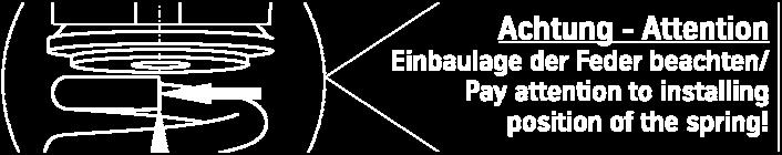
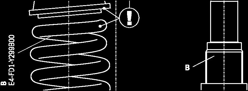
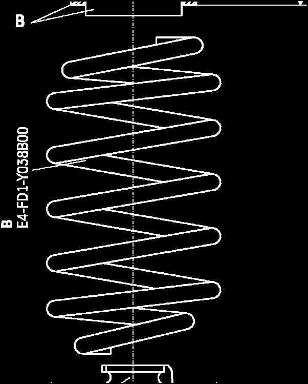
3 mounting instruction for front axle Removal Place vehicle on a wheel-free car hoist, lift it and remove wheels. Vehicles equipped with xenon headlight the movable element of sensor for the headlamp levelling controller must removed before. Pay attention that support wires of brake system are strain-free during removal. Stabilization by suitable means is demanded. Remove bottom mount. Remove top fixing nuts from support bearing. Do not remove central nut at this time! Remove complete strut and clamp it in an appropriate strut vice. Using a suitable spring compressor, compress suspension spring until tension on support bearing is free to move. Release central nut and remove original mounting parts and coil spring. Please refer to diagram to identify which parts will be replaced with BILSTEIN- supplied components. Installation Assemble BILSTEIN and/ or original mounting parts, as well as the new BILSTEIN spring on the BILSTEIN strut in reverse order as removal. IMPORTANT! Spring plates must not be adjusted outside the ranges specified in the certificate! The correct mounting position of the suspension springs can be determined by the printing on the springs; install them with the print upright. The top spring runout must be positioned at the highest point of spring plate slope (see page 5). Do not reuse original- bumper, since BILSTEIN- strut has built in bump stop. Fit assembled BILSTEIN strut to the vehicle in reverse order as removal. Care must be taken to ensure that the power cable is seated correctly in the wheelsuspension raft ( see photo on page 5).


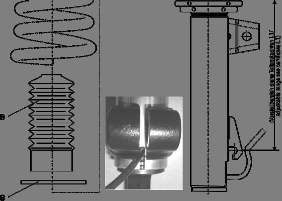

4 front axle
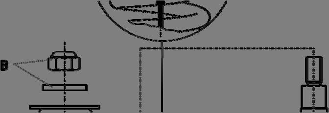
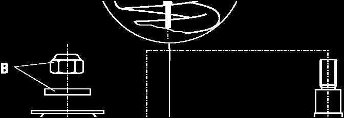
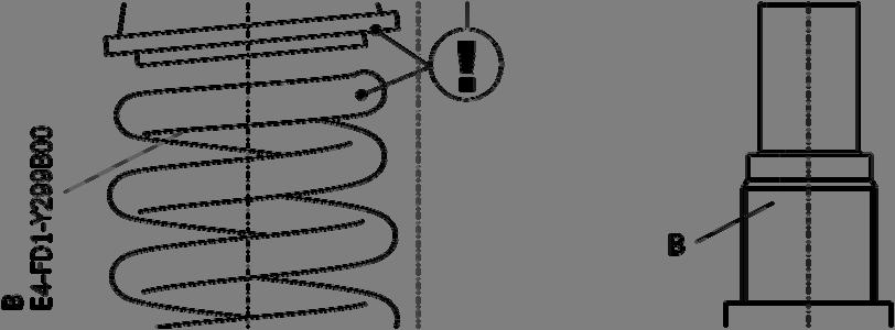
5 mounting instruction for rear axle Removal Place vehicle on a wheel-free car hoist, lift it and remove wheel Pay attention that support wires of brake system are strain-free during removal. Stabilization by suitable means is demanded. Remove top and bottom mount. Remove complete shock absorber and original mounting parts. Installation Drill a hole of ø 12 mm into original support bearing ( see rear axle sketch). Remove and modify original mounting parts acc. to the rear axle sketch, complete with BILSTEIN mounting parts and fit on BILSTEIN shock absorber in reverse order as removal. Fit BILSTEIN shock absorber to the vehicle in reverse order as removal.

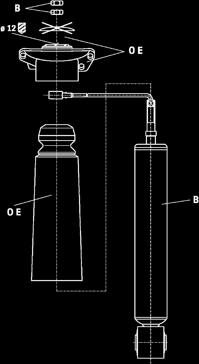
6 rear axle
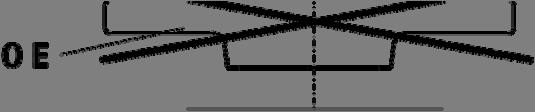


7 adjustment assembly rear axle
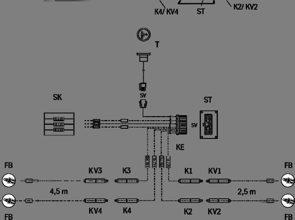
8 Scope of Delivery 1 x control unit ( ST) 1 x wiring harness ( KE): 2 m wire, brown, 0,75 mm² 2 m wire, red, 0,75 mm² 2 m wire, black, 0,75 mm² 3 x connectors 0,5-1,5 mm² 3 x splice wire clamps 0,5-1,5 mm² 3 x crimping connectors ø 8,4 mm 3 x crimping connectors ø 6,5 mm 1 x LED- switch ( T) 2 x extension cable ( KV) 2,5 m 2 x extension cable ( KV) 4,5 m 20 x tie straps
, LED- switch ( T) and for the cables ( K) ( ATTENTION! Location can be different in different vehicles with different equipment).")
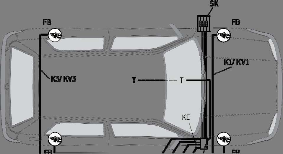
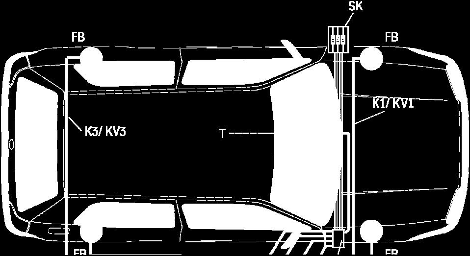
9 Preparations for Installing Remove the plastic cover for cabin ventilation elements at the cowl inside the engine compartment. Determine location for the BILSTEIN control unit ( ST), LED- switch ( T) and for the cables ( K) ( ATTENTION! Location can be different in different vehicles with different equipment). Possible locations are: ST Outside right, next to the glove compartment ( cover must remove; see pic.1) Bild 1/ pic. 1 T Free area of dashboard. Take care that the distance to driver s position is correct! Switch must be accessible to driver when operating the vehicle. Front, at central armrest. K Along existing body holes inside engine bay. Ensure that there is enough free clearance for installation and there are no existing wires/ instruments nearby. ST can be installed in a non-visible location, because there is no need for access after installation; make sure that the type approval number ( e1* ) is readable for TÜV approval or technical inspection! For installation of T a drilled hole of min. ø 18,5 mm / 0.73 is necessary. Take care that all cables do not contact sharp or hot panels. If possible use existing empty conduits. Select connecting points that there is no influence on electronic system. Error messages and malfunction may result. Routing and fastening of cables can be done with tie straps along existing wiring harness. Do not coil extra long cables, as there is danger of self- induction.
10 Installing ( The control unit for our test vehicle was positioned inside passenger compartment) Remove the cover below dashboard. Fasten the BILSTEIN control unit by using supplied Velcro (hook and loop) fastener right next to the glove compartment ports upwards. Connect BILSTEIN control unit ( ST) and wiring harness ( KE) by using the plug ( SV). Connect the terminals ( batt.+, batt.-, ignition) directly with battery pole (batt.+, batt.-) of fuse box ( SK) inside passenger compartment by using delivered cable lugs. Finally all cables must protected with appropriate cover. KL 15 ignition wire (black) Each terminal is marked for easy identification as follows: KL 30 batt.+ wire (red) KL 31 batt.- wire (brown) Check all terminals to avoid short-circuit or defective connection by using a tester before connecting. Fasten wires by using delivered tie straps. Fix the LED button in the previous- made hole in the dashboard or in the center console and secure it with the lock nut from rear side. Guide the cable with the connector ( SV) for the LED button below the dashboard to the button. Connect the plug connection between LED button and cable harness and fix the cable. This is the identification of the cables for connection to the struts / shocks ( FB): front left - VL/ FL - front right - VR/ FR - rear left - HL/ RL - rear right - HR/ RR - Guide the cable for VL from BILSTEIN control panel through the body opening (right beside of ventilation) into the engine compartment, below the plastic cover (cover below the windshield), lead to the left side of the vehicle and through existing openings to the strut. Connect to the protruding cable end of the strut and fix it sufficiently. If necessary use the supplied extension cables ( KV 2,5 m). Guide the cable for VL from BILSTEIN control panel through the body opening (right beside of ventilation) into the engine compartment. Lead through existing openings to the strut. Connect to the protruding cable end of the strut and fix it sufficiently.
11 Guide both cables for the rear from BILSTEIN control panel, along the previously opened footboard at passenger side, along the wiring harness to the backside. The cable for the right shocks lead directly into the wheelhouse through existing body openings to the shock. Connect to the protruding cable end of the shock and fix it sufficiently. Guide the cable for the left shock absorber behind the rear bench seat to the left side of the vehicle. Thence, lead directly into the wheelhouse through existing body openings to the shock. Connect to the protruding cable end of the shock and fix it sufficiently. If necessary use the supplied extension cables ( KV 4,5 m). Operation The BILSTEIN ridecontrol is controlled by the LED- switch ( T). You can select between two settings Comfort and Sport. The base setting is Comfort, with the BILSTEIN ridecontrol switched off. Push the LED- switch to switch the system on (firm) The outer race and a spot in the middle of the switch illuminates blue. Push the LED- switch again to switch the BIL- STEIN ridecontrol off (soft). Error Analysis The LED switch assists you in case problems occur. A blink code, visualized by the spot in the middle of the switch, indicates which problem is preventing an optimal function of the system. Blink duration and pause between the blinks is 1 sec. After a 3 sec. pause the blink code starts again. In case of error message or power failure for any other reason, the BILSTEIN ridecontrol is set to Sport automatically.

12
Contents: - certificate BILSTEIN ridecontrol for multilink rear axle only:
 Contents: - certificate BILSTEIN ridecontrol for multilink rear axle only: AUDI A3,S3,RS3, 3-doors, 4- doors, incl. Sportback and Quattro - SEAT Leon, 2WD und 4WD, incl.st - SKODA Oktavia, sedan and station
After installation please observe the following points: Before installation please observe the following points:
 Before installation please observe the following points: Read all information in this manual carefully. All suspension components are fitted and removed acc. to the manufacturer s specifications for installing
IMPORTANT! READ THIS FIRST!
 IMPORTANT! READ THIS FIRST! Installation of shock absorbers requires special tools and expert knowledge. Accordingly, installation of all BILSTEIN products must be performed by a qualified suspension specialist.
518A00 MOUNTING INSTRUCTION
 IMPORTANT! READ THIS FIRST! Installation of shock absorbers requires special tools and expert knowledge. Accordingly, installation of all BILSTEIN products must be performed by a qualified suspension specialist.
1. General Description
 General Description 1. General Description A: SPECIFICATION Front Rear Model Wheel arch height (Tolerance: +12 mm 24 mm ( +0.47 in 0.94 in)) mm (in) 376 (14.8) Camber (Tolerance: 0 45 Differences between
E4-WM5-Y530A00 MOUNTING INSTRUCTION
 IMPORTANT! READ THIS FIRST! Installation of shock absorbers requires special tools and expert knowledge. Accordingly, installation of all BILSTEIN products must be performed by a qualified suspension specialist.
E4-WM5-Y556A00 MOUNTING INSTRUCTION
 IMPORTANT! READ THIS FIRST! Installation of shock absorbers requires special tools and expert knowledge. Accordingly, installation of all BILSTEIN products must be performed by a qualified suspension specialist.
B8 5112/5162 LEVELING KIT (FRONT) RAM x4 GAS
 RAM x4 GAS") B8 5112/5162 LEVELING KIT (FRONT) 2014+ RAM 2500 4x4 GAS IMPORTANT! READ THIS FIRST! Installation of shock absorbers requires special tools and expert knowledge. Accordingly, installation of all BILSTEIN
B8 5112/5162 LEVELING KIT (FRONT) 2014+ RAM 2500 4x4 GAS IMPORTANT! READ THIS FIRST! Installation of shock absorbers requires special tools and expert knowledge. Accordingly, installation of all BILSTEIN
PRO STREET-S INSTALLATION INSTRUCTIONS
 PARTS & HARDWARE LIST Part Number Description Qty Part Number Description Qty A 1534.8100 DAMPER ASSY FRONT 2 B 1534.8200 DAMPER ASSY REAR 2 C PDK4.TOOL 4mm ADJUSTMENT TOOL 1 D PDK6.TOOL 6mm ADJUSTMENT
Saab 9-3 CV M04-, 4D/5D M06-
 SCdefault 900 Installation instructions SITdefault MONTERINGSANVISNING INSTALLATION INSTRUCTIONS MONTAGEANLEITUNG INSTRUCTIONS DE MONTAGE Sports chassis Accessories Part No. Group Date Instruction Part
IMPORTANT! READ THIS FIRST!
 MPORTANT! READ THS FRST! nstallation of shock absorbers requires special tools and expert knowledge. Accordingly, installation of all BLSTEN products must be performed by a qualified suspension specialist.
Jeep Grand Cherokee ZJ 4 Suspension Kit
 92168800 Jeep Grand Cherokee 93-98 ZJ 4 Suspension Kit Thank you for choosing Rough Country for all your suspension needs. Rough Country recommends a certified technician install this system. In addition
Accessory Kit Estimated Fitting Time: 120 Minutes
 Landcruiser LC00 Tow-Pro Wiring Kit - Landcruiser LC00 Kit Part No: TPWKIT - 005 Accessory Kit Estimated Fitting Time: 0 Minutes FI88 Page 0 of Issue: Date: 7/09/07 07 General Notes Safety Notes Parts
P Original Series Cargo Van Lift Mounting Instructions Fullsize Ford Van present. Preparing the Gate
 Fullsize Ford Van- 1992-present Preparing the Gate 1. Remove the mounting hardware which is banded to the liftgate. 2. Verify mounting kit (Figure 1 and Table 1). S-400-40 STRAP VAN MOUNTING EAR BENT BRACKET
Installation Instructions
 Installation Instructions Eibach Springs, Inc. 264 Mariah Circle Corona, California 92879-1751 USA Tech Support 800-222-8811 Ext 114 Eibach Multi-Pro R1 Coilovers - #2085.712 2006-2008 BMW, 325i, 328i,
HP10134 & HP10135 KITS BASIC SIMULTANEOUS AIR SPRING ACTIVATION KIT
 HP10134 & HP10135 KITS BASIC SIMULTANEOUS AIR SPRING ACTIVATION KIT Thank you and congratulations on the purchase of a Pacbrake simultaneous air spring activation kit. This kit was designed to add in-cab
SUSPENSION SYSTEM PROBLEM SYMPTOMS TABLE SP 1
 SUENSION SUENSION SYSTEM 1 SUENSION SYSTEM Suspension system Vehicle is unstable Bottoming Sways/pitches Wheels shimmy Abnormal tire wear Vehice pull PROBLEM SYMPTOMS TABLE Use the table below to help
Emergency response guide
 Emergency response guide ΛΦ 20426 DAF Trucks N.V., Eindhoven, The Netherlands. In the interest of continuing product development, DAF reserves the right to change specifications or products at any time
SCdefault. 900 Installation instructions
 SCdefault 900 Installation instructions SITdefault Installation kit, extra lights MONTERINGSANVISNING INSTALLATION INSTRUCTIONS MONTAGEANLEITUNG INSTRUCTIONS DE MONTAGE Accessories Part No. Group Date
SCdefault. 900 Installation instructions
 SCdefault 900 Installation instructions SITdefault Sports chassis MONTERINGSANVISNING INSTALLATION INSTRUCTIONS MONTAGEANLEITUNG INSTRUCTIONS DE MONTAGE Accessories Part No. Group Date Instruction Part
Installation Instructions
 Installation Instructions Eibach Springs, Inc. 264 Mariah Circle Corona, California 92879-1751 USA Tech Support 800-222-8811 Ext 114 Eibach Pro Street Coilovers - #8598.711 2006-2008 Volkswagen, GTi, 2.0L
NOTICE TO DEALER AND VEHICLE OWNER
 921332300 *1332BAG1* 1332BAG1 2012-18 DODGE 1500 6 LIFT KIT Thank you for choosing Rough Country for all your suspension needs. Rough Country recommends a certified technician install this system. In addition
SCION tc LOWERING SPRINGS Preparation
 Preparation Part Number: PTR11-21100 PTR11-21100-50 Kit Contents Item # Quantity Reqd. Description 1 2 Front Spring 2 2 Rear Spring 3 2 Locking Nut 4 2 Spring Bumper, Front 5 1 Instruction Form Hardware
900 Installation instructions. SCdefault
 12 788 439 1 SCdefault 900 Installation instructions SITdefault Timer kit MONTERINGSANVISNING INSTALLATION INSTRUCTIONS MONTAGEANLEITUNG INSTRUCTIONS DE MONTAGE Accessories Part No. Group Date Instruction
GROUP 33A 33A-1 CONTENTS GENERAL DESCRIPTION... 33A-2 FRONT SUSPENSION DIAGNOSIS. 33A-3 LOWER ARM... 33A-13 SPECIAL TOOLS... 33A-5
 33A-1 GROUP 33A CONTENTS GENERAL DESCRIPTION 33A-2 DIAGNOSIS 33A-3 INTRODUCTION TO FRONT SUSPENSION DIAGNOSIS 33A-3 DIAGNOSIS TROUBLESHOOTING STRATEGY 33A-3 SYMPTOM CHART 33A-3 SYMPTOM PROCEDURES 33A-3
FRONT SUSPENSION GROUP 33A 33A-1 CONTENTS GENERAL DESCRIPTION... 33A-2 FRONT SUSPENSION DIAGNOSIS. 33A-3 LOWER ARM... 33A-13 SPECIAL TOOLS...
 33A-1 GROUP 33A FRONT SUSPENSION CONTENTS GENERAL DESCRIPTION......... 33A-2 DIAGNOSIS. 33A-3 INTRODUCTION TO DIAGNOSIS........................ 33A-3 DIAGNOSIS TROUBLESHOOTING STRATEGY...... 33A-3 SYMPTOM
PRE-INSTALLATION. INSTALLATION INSTRUCTIONS Front Dodge Ram WD 6" Suspension Lift Kit
 2012-2015 Dodge Ram 1500 4WD 6" Suspension Lift Kit PRE-INSTALLATION 35015 2 - Knuckle (Driv/Pass) 2 - Crossmember (Front/Rear) 2 - Differential Bracket (Driv/Pass) 1 - Diff. Brace Bracket (Pass) 2 - Front
FRONT WHEEL ALIGNMENT
 2 Front: B A A Rear: C D Front SUENSION FRONT WHEEL ALIGNMENT D F046082E03 B FRONT WHEEL ALIGNMENT ADJUSTMENT 1. INECT TIRE (a) Inspect the tires (see page TW-3). 2. MEASURE VEHICLE HEIGHT Standard vehicle
Suspension System RS6582B
 Suspension System RS6582B Tahoe/Yukon READ ALL INSTRUCTIONS THOROUGHLY FROM START TO FINISH BEFORE BEGINNING INSTALLATION IMPORTANT NOTES! WARNING: This suspension system will enhance the off-road performance
Towing and Road Service Guide For 2013 Lexus GS. Quality and Education Services AAA Automotive 1000 AAA Drive Heathrow, FL 32746
 Towing and Road Service Guide For 2013 Lexus GS Quality and Education Services AAA Automotive 1000 AAA Drive Heathrow, FL 32746 March 5, 2012 Index General Towing Information Special Precautions 1 Car
*1609BAG8* 1609BAG8 JEEP JK 3 1/2 SUSPENSION KIT A
 JEEP JK 3 1/2 SUSPENSION KIT 92160900A *1609BAG8* 1609BAG8 Thank you for choosing Rough Country for your suspension needs. Please read instructions before beginning installation. Check the kit hardware
SUSPENSION SYSTEM PROBLEM SYMPTOMS TABLE SP 1
 SUENSION SUENSION SYSTEM 1 Vehicle/pulls Bottoming Sway/pitches Wheel shimmy Abnormal tire wear SUENSION SYSTEM PROBLEM SYMPTOMS TABLE Use the table below to help determine the cause of the problem. The
This file is available for free download at
 This file is available for free download at http://www.iluvmyrx7.com This file is fully text-searchable select Edit and Find and type in what you re looking for. This file is intended more for online viewing
Motronic ignition system, servicing
 Page 1 of 25 28-2 Motronic ignition system, servicing Note: Motronic Engine Control Module (ECM) J220* with connector page 24-9, item 16. 1 - Highvoltage ignition cable Ignition secondary circuit Check
PRODUCT SAFETY NOTICE
 PRODUCT SAFETY NOTICE Congratulations. This vehicle has been equipped with a Firestone air suspension system. This suspension will enhance the vehicle s handling when loaded, however, the vehicle s performance
Thank you for choosing Rough Country for all your suspension needs.
 06-UP JEEP COMMANDER 2 LIFT KIT Thank you for choosing Rough Country for all your suspension needs. Rough Country recommends a certified technician install this system. In addition to these instructions,
B29048, B29049, B29050, B29051, B29053, B
 May 1, 2011 Lit. No. 48266, Rev. 05 B29048, B29049, B29050, B29051, B29053, B29400-5 HARNESS KIT 3-PORT ISOLATION MODULE LIGHT SYSTEM w/2-plug SYSTEM HARNESSES Installation Instructions Read this document
Installation Instructions
 Installation Instructions Eibach Springs, Inc. 264 Mariah Circle Corona, California 92879-1751 USA Tech Support 800-222-8811 Ext 114 Eibach Pro Street-S Coilovers - #2895.711 2009 Dodge Challenger, R/T,
07-11 GM 1500 Pickup, Avalanche, Yukon, Tahoe, Suburban Front 2.5 Kit
 92130500 07-11 GM 1500 Pickup, Avalanche, Yukon, Tahoe, Suburban Front 2.5 Kit Thank you for choosing Rough Country for all your suspension needs. Rough Country recommends a certified technician install
NOTICE TO DEALER AND VEHICLE OWNER
 921322300 *1322BAG1* 1322BAG1 2009-17 Dodge 2wd 1500 6 Lift Kit Thank you for choosing Rough Country for all your suspension needs. Rough Country recommends a certified technician install this system.
IMPORTANT! READ THIS FIRST!
 MPORTANT! READ THS FRST! nstallation of shock absorbers requires special tools and expert knowledge. Accordingly, installation of all BLSTEN products must be performed by a qualified suspension specialist.
KIT # Figure 1. Figure 2. Figure 3
 KIT #60748 BY MN-330 (02809) ECR6529 1. Jack up rear of vehicle or raise on hoist. Support frame with safety stands. Remove lower shock absorber attaching bolts. CUT BOTTOM (2) SECTIONS OFF RUBBER BUMP
650 Series Cargo Van Lift Mounting Instructions Ford Transit (Standard Roof) 2015-Present
 2015-Present") TOMMY GATE OWNER'S / OPERATOR'S MANUAL 650 Series 650 LB Capacity 650 Series Cargo Van Lift Mounting Instructions Ford Transit (Standard Roof) 2015-Present Installing the Base Plate 1. Examine the interior
TOMMY GATE OWNER'S / OPERATOR'S MANUAL 650 Series 650 LB Capacity 650 Series Cargo Van Lift Mounting Instructions Ford Transit (Standard Roof) 2015-Present Installing the Base Plate 1. Examine the interior
VECTRIX VX-2 SERVICE MANUAL. Version 1.0/May 2011 VECTRIX, LLC
 www.vectrix.com CONTENTS SECTION A: Tools 1 Tools Needed SECTION B: Mechanical Parts 1 Front Fairing 2 Front Console Cover 3 Speedometer Cover 4 Front Vertical Panel Cover-Lower 5 Front Vertical Panel
Hayes TrailTrac Kit Installation Guidelines Polaris Rush / Pro-R / Indy
 Models: 2010-2014 Polaris Rush / Pro-R / Indy Packing List 1 Electronic Control Unit (ECU) 1 ECU Velcro, 3 inch 1 Switch face plate 1 Switch face plate adhesive 1 Switch 1 Wiring harness 1 Fully pre-filled
Emergency response guide
 Emergency response guide 20408 DAF Trucks N.V., Eindhoven, The Netherlands. In the interest of continuing product development, DAF reserves the right to change specifications or products at any time without
TOYOTA PRIUS PLUS LOWERING SPRINGS Preparation
 Preparation Part Number: PTR07-47100 Kit Contents Item # Quantity Reqd. Description 1 2 Front Spring 2 2 Rear Spring 3 2 Nut 4 1 Instructions Hardware Bag Contents Item # Quantity Reqd. Description 1 2
2014 F /6 LIFT KIT
 92157500 2014 F-150 4 /6 LIFT KIT THANK YOU FOR CHOOSING ROUGH COUNTRY FOR YOUR SUSPENSION NEEDS. Rough Country recommends a certified technician install this system. In addition to these instructions,
Installation Instructions
 Installation Instructions 6 Suspension System FTS25005BK / FTS25006BK 2006-2012 Nissan Frontier 2wd/4wd SHORT BED ONLY Tool List: (not included) Floor Jack & Jack Stands Assorted Metric & S.A.E Sockets
TESTING & REPAIR > REMOVE/INSTALL FRONT SHOCK ABSORBER - AR32.25-P-0105RT
 Page 1 of 8 Service Manual: SUSPENSION -- R500/R63 Print Date: TESTING & REPAIR > REMOVE/INSTALL FRONT SHOCK ABSORBER - AR32.25-P-0105RT 2006 Mercedes-Benz R500 5.0L Eng MODELS 251 except CODE (489) Airmatic
INSTALLATION INSTRUCTIONS
 INSTALLATION INSTRUCTIONS Accessory P/N 08E10-TA0-100 Application 2008 ACCORD 2-AND 4-DOOR Publications No. AII 35358 Issue Date AUG 2007 PARTS LIST Ambient Light Kit 2 Ambient lights Fuse label Washer
INSTALLATION INSTRUCTIONS 88029
 INSTALLATION INSTRUCTIONS 88029 FOR SUSPENSION SYSTEMS RS6503: JEEP WRANGLER (TJ) READ ALL INSTRUCTIONS THOROUGHLY FROM START TO FINISH BEFORE BEGINNING INSTALLATION REV F IMPORTANT NOTES! WARNING: This
Kit INSTALLATION GUIDE. 5 psi Low Pressure Sensor (Single Gauge)
") ª Kit 25592 5 psi Low Pressure Sensor (Single Gauge) MN-333 (131107) ECR 7119 INSTALLATION GUIDE For maximum effectiveness and safety, please read these instructions completely before proceeding with installation.
ª Kit 25592 5 psi Low Pressure Sensor (Single Gauge) MN-333 (131107) ECR 7119 INSTALLATION GUIDE For maximum effectiveness and safety, please read these instructions completely before proceeding with installation.
ALWAYS follow all Webasto installation and repair instructions and observe all warning instructions.
 Water heater unit Feel drive Thermo Top E Auxiliary Heating Thermo Top C Auxiliary Heating Thermo Top P Auxiliary Heating e 00 000 e 00 000 e 00 004 Installation instructions Toyota RAV 4 Petrol From model
2003 FORESTER SERVICE MANUAL QUICK REFERENCE INDEX
 2003 FORESTER SERVICE MANUAL QUICK REFERENCE INDEX CHASSIS SECTION FRONT SUSPENSION FS REAR SUSPENSION RS WHEEL AND TIRE SYSTEM WT This service manual has been prepared to provide SUBARU service personnel
Installation Guide for the TeraFlex Elite LCG JK 4 Long Arm Suspension System
 Tera Manufacturing, Inc. 5251 South Commerce Dr. Murray, Utah 84107 Phone/801.288.2585 Fax/801.713.2313 www.teraflex.biz INSTALLATION GUIDE Installation Guide for the TeraFlex Elite LCG JK 4 Long Arm Suspension
INSTALLATION INSTRUCTIONS
 28 INSTALLATION INSTRUCTIONS SECTION - AIR SPRING SECTION 2 - AIR ACCESSORY 2-5 ! IMPORTANT PLEASE DON T HURT YOURSELF, YOUR KIT OR YOUR VEHICLE. TAKE A MINUTE TO READ THIS IMPORTANT INFORMATION. This
SERVICE MANUAL. Permobil C350. Power Wheelchair
 SERVICE MANUAL US Permobil C350 Power Wheelchair Contents Contents Introduction... 5 Rating plates... 6 Covers... 8 Batteries... 10 Rear wheels... 12 Support wheels... 14 Front wheels... 16 Wheel fork...
PRODUCT SAFETY NOTICE DEALER/INSTALLER NOTICE
 PRODUCT SAFETY NOTICE Congratulations. This vehicle has been equipped with a Firestone air suspension system. This suspension will enhance the vehicle s handling when loaded, however, the vehicle s performance
TOYOTA COROLLA LOWERING SPRINGS Preparation
 Preparation Part Number: PTR07-02140 Kit Contents Item # Quantity Reqd. Description 1 2 Front Spring 2 2 Rear Spring 3 1 Hardware 4 1 Instruction Form Hardware Bag Contents Item # Quantity Reqd. Description
ENGINE REMOVAL & INSTALLATION
 TORQUE VALUES ENGINE MOUNTING = Apply Victory All Purpose Grease 2872187 1. Install all bolts in order A-H Do not tighten. E 41 Nm (30 lb-ft) M8 x 25mm D 111 Nm (82 lb-ft) 12 x 100mm ENGINE INSTALLATION
AUXILIARY BATTERY BOX INSTALLATION INSTRUCTIONS
 AUXILIARY BATTERY BOX INSTALLATION INSTRUCTIONS The original TOMMY GATE hydraulic lift Assembling the Auxiliary Battery Box 1. Remove the cover from the auxiliary battery box by removing the two nuts and
29048, 29049, 29050, 29051, 29052, 29053, 29054,
 April 15, 2014 Lit. No. 29225, Rev. 11 29048, 29049, 29050, 29051, 29052, 29053, 29054, 29400 5 HARNESS KIT 3 PORT ISOLATION MODULE LIGHT SYSTEM w/2 PLUG SYSTEM HARNESSES Installation Instructions Read
Kit psi Low Pressure Sensor (Dual Gauge)
") ª Kit 25812 5 psi Low Pressure Sensor (Dual Gauge) MN-337 (111107) ECR 7119 INSTALLATION GUIDE For maximum effectiveness and safety, please read these instructions completely before proceeding with installation.
ª Kit 25812 5 psi Low Pressure Sensor (Dual Gauge) MN-337 (111107) ECR 7119 INSTALLATION GUIDE For maximum effectiveness and safety, please read these instructions completely before proceeding with installation.
*1553BAG3* F-150 2WD 4 /5 /6 LIFT KIT 1553BAG3
 *1553BAG3* 1553BAG3 921553220 2015-16 F-150 2WD 4 /5 /6 LIFT KIT THANK YOU FOR CHOOSING ROUGH COUNTRY FOR YOUR SUSPENSION NEEDS. Rough Country recommends a certified technician install this system. In
IMPORTANT! PLEASE READ ALL INSTRUCTIONS FIRST!
 IMPORTANT! PLEASE READ ALL INSTRUCTIONS FIRST! If in doubt, please contact your local BILSTEIN dealer or our sales department before installation. When replacing other brands, BILSTEIN shock absorbers
SELF DRILL SCREWS FILLER STRIP
 r ve Pickup Lift Mounting Instructions Fullsize Ford Trucks- F-150 2015-present Preparing the Gate 1. Remove the mounting hardware which is banded to the liftgate. 2. Verify mounting bracket kit (Figure
HARNESS KIT 3-PORT ISOLATION MODULE LIGHT SYSTEM
 October 1, 2018 Lit. No. 92988, Rev. 00 72199 HARNESS KIT 3-PORT ISOLATION MODULE LIGHT SYSTEM Parts List and Installation Instructions Read this document before installing the harness kit. See your sales
650 Series Cargo Van Lift Mounting Instructions Fullsize Ford 1992-Present
 TOMMY GATE OWNER'S / OPERATOR'S MANUAL 650 Series 650 LB Capacity 650 Series Cargo Van Lift Mounting Instructions Fullsize Ford 1992-Present Installing the Base Plate 1. Examine the interior and exterior
INSTALLATION INSTRUCTIONS
 2807 INSTALLATION INSTRUCTIONS SECTION - AIR SPRING SECTION 2 - AIR ACCESSORY -6 ! IMPORTANT PLEASE DON T HURT YOURSELF, YOUR KIT OR YOUR VEHICLE. TAKE A MINUTE TO READ THIS IMPORTANT INFORMATION. This
09-UP F150 2WD 6 LIFT KIT
 92157300 09-UP F150 2WD 6 LIFT KIT THANK YOU FOR CHOOSING ROUGH COUNTRY FOR YOUR SUSPENSION NEEDS. Rough Country recommends a certified technician install this system. In addition to these instructions,
09-13 FORD F150 4 LIFT KIT
 92159900 09-13 FORD F150 4 LIFT KIT THANK YOU FOR CHOOSING ROUGH COUNTRY FOR YOUR SUSPENSION NEEDS. Rough Country recommends a certified technician install this system. In addition to these instructions,
1990 SUSPENSION Front ES250, LS400
 SUSPENSION - FRONT Article Text 1990 Lexus LS 400 For Lextreme Copyright 1998 Mitchell Repair Information Company, LLC Thursday, January 29, 2004 04:56PM ARTICLE BEGINNING 1990 SUSPENSION Front ES250,
Installation Instructions
 Installation Instructions Eibach Springs, Inc. 264 Mariah Circle Corona, California 92879-1751 USA Tech Support 800-222-8811 Ext 114 Eibach Pro Street-S Coilovers - #28110.711 2011-13 Dodge Challenger
and Original Series Pickup Lift Mounting Instructions Fleetside Chevy & GMC Trucks Fleetside 4-door Chevy & GMC Trucks T-100
 r ve and Original Series Pickup Lift Mounting Instructions Fleetside Chevy & GMC Trucks - 1960-1987 Fleetside 4-door Chevy & GMC Trucks - 1988-1991 Preparing the Gate 1. Remove the mounting hardware which
TOYOTA SOLARA CONVERTIBLE XM SATELLITE RADIO Preparation. Part Number: Mounting Kit PT
 Preparation Part Number: Mounting Kit PT546-06061 Tuner Assy 86180-0W030 Tuner Assy Kit Contents (86180-0W030) 1 1 Tuner Assy, Stereo Component Mounting Kit Contents (PT546-06061) 1 Ground Cable 1 1 Wire,
Performance Suspension Parts INSTALLATION INSTRUCTIONS
 Performance Suspension Parts INSTALLATION INSTRUCTIONS Before you start installation work, please read the following carefully: - Ensure that the TUEV certificate matches the vehicle specifications (front
97-06 JEEP TJ/LJ LONG ARM UPGRADE KIT
 921663U00 97-06 JEEP TJ/LJ LONG ARM UPGRADE KIT Thank you for choosing Rough Country for your suspension needs. This kit is an upgrade kit only. This kit includes frame mounting points and adjustable long
29048, 29049, 29050, 29051, 29052, 20953, 29054,
 July 15, 2008 Lit. No. 29225, Rev. 06 29048, 29049, 29050, 29051, 29052, 20953, 29054, 29400-2 HARNESS KIT 3-PORT ISOLATION MODULE LIGHT SYSTEM w/2-plug SYSTEM HARNESSES Installation Instructions Read
2015 F /5 /6 LIFT KIT
 92155700 2015 F-150 4 /5 /6 LIFT KIT THANK YOU FOR CHOOSING ROUGH COUNTRY FOR YOUR SUSPENSION NEEDS. Rough Country recommends a certified technician install this system. In addition to these instructions,
Jeep Wrangler (JK)
") 89109 Rev B Suspension Systems RS66109BR5 and RS66109BR9 2007 2013 Jeep Wrangler 4 Door Sport and Rubicon Models (2 SPORT SYSTEM) Jeep Wrangler (JK) 2007-2013 89109 Rev B READ ALL INSTRUCTIONS THOROUGHLY
89109 Rev B Suspension Systems RS66109BR5 and RS66109BR9 2007 2013 Jeep Wrangler 4 Door Sport and Rubicon Models (2 SPORT SYSTEM) Jeep Wrangler (JK) 2007-2013 89109 Rev B READ ALL INSTRUCTIONS THOROUGHLY
(877) MON-FRI 7AM-5PM PST OR WEBSITE: ReadyLIFT.COM **Please retain this document in your vehicle at all times**
 MON-FRI 7AM-5PM PST OR WEBSITE: ReadyLIFT.COM **Please retain this document in your vehicle at all times**") IF YOUR ReadyLIFT PRODUCT IS MISSING A OR HAS A DAMAGED PART, PLEASE CONTACT CUSTOMER SERVICE DIRECTLY. For warranty issues please return to the place of installation and contact ReadyLIFT. A NEW REPLACEMENT
IF YOUR ReadyLIFT PRODUCT IS MISSING A OR HAS A DAMAGED PART, PLEASE CONTACT CUSTOMER SERVICE DIRECTLY. For warranty issues please return to the place of installation and contact ReadyLIFT. A NEW REPLACEMENT
Water heater unit. Installation instructions. Peugeot Partner. Citroen Berlingo. Supplementary heating Thermo Top C. Table of Contents.
 Water heater unit Feel the drive Supplementary heating Thermo Top C e1 00 0002 Installation instructions Peugeot Partner Citroen Berlingo 6 4 1 2 3 5 Gasoline and diesel From model year 2003 Only for left-hand
JEEP JK 6 2 DR X-SERIES SUSPENSION KIT
 921684X00 Thank you for choosing Rough Country for your suspension needs. JEEP JK 6 2 DR X-SERIES SUSPENSION KIT Rough Country recommends a certified technician install this system. In addition to these
1 M-3000-H4 F150 4X4 Lowering Kit
 READ INSTRUCTIONS COMPLETELY THROUGH BEFORE STARTING. IT IS RECOMMENDED THAT INSTALLATION BE DONE BY A QUALIFIED MECHANIC. REPLACE ALL STOCK PARTS THAT ARE DAMAGED OR WORN. ALWAYS WEAR EYE PROTECTION.
SCION tc SECURITY (V5) Preparation
 Preparation") Preparation Part Number: PT398-21070 Kit Contents Item # Quantity Reqd. Description 1 1 2 1 GBS ECU Hardware Bag Contents Item # Quantity Reqd. Description 1 1 V5 Security ECU 2 1 ECU Mounting Bracket
Preparation Part Number: PT398-21070 Kit Contents Item # Quantity Reqd. Description 1 1 2 1 GBS ECU Hardware Bag Contents Item # Quantity Reqd. Description 1 1 V5 Security ECU 2 1 ECU Mounting Bracket
INSTALLATION INSTRUCTION Rev A
 INSTALLATION INSTRUCTION 88587 Rev A FOR RANCHO SUSPENSION SYSTEM RS6587B: 2009 DODGE RAM 1500 READ ALL INSTRUCTIONS THOROUGHLY FROM START TO FINISH BEFORE BEGINNING INSTALLATION IMPORTANT NOTES! WARNING:
Return To Main Table of Contents GENERAL... 2 STRUT ASSEMBLY LOWER ARM STABILIZER BAR CENTER MEMBER WHEEL AND TIRE...
 FRONT SUSPENSION Return To Main Table of Contents GENERAL... 2 STRUT ASSEMBLY... 11 LOWER ARM... 13 STABILIZER BAR... 17 CENTER MEMBER... 19 WHEEL AND TIRE... 21 GENERAL GENERAL SPECIFICATIONS Suspension
29048, 29049, 29050, 29051, 29052, 29053, 29054,
 May 1, 2018 Lit. No. 29206, Rev. 13 29048, 29049, 29050, 29051, 29052, 29053, 29054, 29400 7 HARNESS KIT 3 PORT ISOLATION MODULE LIGHT SYSTEM w/3 PLUG SYSTEM HARNESSES Installation Instructions Read this
Engineered to Ride, Built to last
 Congratulations on your selection to purchase an Arnott Air Suspension System. We at Arnott Air Suspension Systems are proud to offer a high quality product at the industries most competitive pricing.
Front and Rear Suspension Modification Kit Installation
 Page 1 of 12 2014 Chevrolet Sonic (US/Canada) Sonic US/Canada Accessory Installation Manual Accessories Performance Accessories Accessories Document ID: 3471343 Front and Rear Suspension Modification Kit
INSTALLATION INSTRUCTIONS Air Spring Kit Dodge WD IMPORTANT NOTES
 INSTALLATION INSTRUCTIONS 6211 Air Spring Kit 2003+ Dodge 1500 4WD Thank you for purchasing a quality Hellwig Product. PLEASE READ THIS INSTRUCTION SHEET COMPLETELY BEFORE STARTING YOUR INSTALLATION IMPORTANT
JEEP JK 4 LONGARM. Tools Needed: Thank you for choosing Rough Country for your suspension needs.
 921786000 Thank you for choosing Rough Country for your suspension needs. JEEP JK 4 LONGARM Rough Country recommends a certified technician install this system. In addition to these instructions, professional
INSTALLATION INSTRUCTION 88581
 INSTALLATION INSTRUCTION 88581 FOR RANCHO SUSPENSION SYSTEM RS6581B: DODGE RAM READ ALL INSTRUCTIONS THOROUGHLY FROM START TO FINISH BEFORE BEGINNING INSTALLATION Rev C IMPORTANT NOTES! WARNING: This suspension
*1557BAG12* 1557BAG F /5 /6 LIFT KIT G THANK YOU FOR CHOOSING ROUGH COUNTRY FOR YOUR SUSPENSION NEEDS.
 2015-18 F-150 4 /5 /6 LIFT KIT THANK YOU FOR CHOOSING ROUGH COUNTRY FOR YOUR SUSPENSION NEEDS. 92155700G *1557BAG12* 1557BAG12 Rough Country recommends a certified technician install this system. In addition
Installation Instructions LamboStyleDoors (The instruction are to be used as a reference. Please repeat for both doors)
") Installation Instructions LamboStyleDoors (The instruction are to be used as a reference. Please repeat for both doors) Pre installation check list: - Double check vehicles data with TUV certificate -
Installation Instructions LamboStyleDoors (The instruction are to be used as a reference. Please repeat for both doors) Pre installation check list: - Double check vehicles data with TUV certificate -
INSTALLATION INSTRUCTION
 1551 S. Vineyard Avenue Ontario, CA 91761 (909) 923-1973 INSTALLATION INSTRUCTION Club Car Precedent Installation Notes CURTIS 1234, 1236 OR 1238 AC INDUCTION MOTOR/ CONTROLLER REVISION: B This kit is
E4-WM5-Y366A00 MOUNTING INSTRUCTION
 E4-WM5-Y366A00 MOUNTINGINSTRUCTION IMPORTANT! PLEASE READ ALL INSTRUCTIONS FIRST! If in doubt, please contact your local BILSTEIN dealer or our sales department before installation. When replacing other
FAX
 INSTALLATION INSTRUCTIONS 6299 Air Suspension Kit (pat. pending) 2009+ Dodge 1500 Pickup with Rear Coil Springs Thank you for purchasing a quality Hellwig Product. PLEASE READ THIS INSTRUCTION SHEET COMPLETELY
»Product» Safety Warning
 C2402, C2602 Installation Instructions 2007-2013 Chevy 1/2 Ton 2wd Pickup 4.5", 6.5" Suspension System Read and understand all instructions and warnings prior to installation of product and operation of