ColorMax 2 Powder Coating System with Encore Feed Center
|
|
|
- Austen Richard
- 5 years ago
- Views:
Transcription
1 ColorMax 2 Powder Coating System with Encore Feed Center Customer Product Manual Issued 10/15 For parts and technical support, call the Industrial Coating Systems Customer Support Center at (800) or contact your local Nordson representative. This document is subject to change without notice. Check for the latest version. NORDSON CORPORATION AMHERST, OHIO USA
2 Contact Us Nordson Corporation welcomes requests for information, comments, and inquiries about its products. General information about Nordson can be found on the Internet using the following address: Address all correspondence to: Nordson Corporation Attn: Customer Service 555 Jackson Street Amherst, OH Notice This is a Nordson Corporation publication which is protected by copyright. Original copyright date No part of this document may be photocopied, reproduced, or translated to another language without the prior written consent of Nordson Corporation. The information contained in this publication is subject to change without notice. Trademarks ColorMax, icontrol, Nordson, and the Nordson logo are registered trademarks of Nordson Corporation. AeroDeck and AeroWash are trademarks of Nordson Corporation.
3 Change Record i Revision Date Change Change Record 02 04/15 Replaced part number with part number Changed screen 8 from minutes to minutes /15 Added slidegate assembly parts /15 Replaced part number with part number Added part number (12-valve pilot solenoid).
4 ii Change Record
5 Table of Contents iii Table of Contents Safety Introduction Qualified Personnel Intended Use Regulations and Approvals Personal Safety Fire Safety Grounding Action in the Event of a Malfunction Disposal Description Introduction System Components Booth Reclaim System Feed Center Automatic Gun Movers/Gun Blow-Off Afterfilter Afterfilter Operation Control Panels Encore Venturi Feed Center Control Panel Main Electrical Control Panel Typical System Options Roll-On/Roll-Off System Operation Introduction Typical Operating Settings Operating Air Pressures Timer Board Settings Booth Control Functions Changing Function Values Startup Ancillary Equipment Clean Function Color Change Procedures Powder Level Sensor Operation Booth Moving Shutdown
6 iv Table of Contents Maintenance Initial Canopy Conditioning Daily Maintenance System Cleaning Daily Equipment Maintenance Weekly Maintenance Monthly Maintenance Booth Canopy Conditioning Cyclone Cleaning HDLV Transfer Pump and Transfer Pan Maintenance Transfer Pan Cleaning Disassembly Cleaning Assembly Emptying the Afterfilter Waste Hoppers Maintenance Check List Troubleshooting Common Problems Reversing Motor Direction Repair Introduction Cartridge Filter Replacement Filter Removal Filter Installation Seasoning the Cartridge Filters Final Filter Replacement Pulse Valve Replacement Preparation Parts Introduction Afterfilter Parts Gun Blow-Off Parts Miscellaneous Parts System Diagram
7 Safety 1-1 Section 1 Safety Introduction Read and follow these safety instructions. Task- and equipment-specific warnings, cautions, and instructions are included in equipment documentation where appropriate. Make sure all equipment documentation, including these instructions, is accessible to all persons operating or servicing equipment. Qualified Personnel Equipment owners are responsible for making sure that Nordson equipment is installed, operated, and serviced by qualified personnel. Qualified personnel are those employees or contractors who are trained to safely perform their assigned tasks. They are familiar with all relevant safety rules and regulations and are physically capable of performing their assigned tasks. Intended Use Use of Nordson equipment in ways other than those described in the documentation supplied with the equipment may result in injury to persons or damage to property. Some examples of unintended use of equipment include using incompatible materials making unauthorized modifications removing or bypassing safety guards or interlocks using incompatible or damaged parts using unapproved auxiliary equipment operating equipment in excess of maximum ratings Regulations and Approvals Make sure all equipment is rated and approved for the environment in which it is used. Any approvals obtained for Nordson equipment will be voided if instructions for installation, operation, and service are not followed.
8 1-2 Safety All phases of equipment installation must comply with all federal, state, and local codes. Personal Safety Fire Safety To prevent injury follow these instructions. Do not operate or service equipment unless you are qualified. Do not operate equipment unless safety guards, doors, or covers are intact and automatic interlocks are operating properly. Do not bypass or disarm any safety devices. Keep clear of moving equipment. Before adjusting or servicing any moving equipment, shut off the power supply and wait until the equipment comes to a complete stop. Lock out power and secure the equipment to prevent unexpected movement. Relieve (bleed off) hydraulic and pneumatic pressure before adjusting or servicing pressurized systems or components. Disconnect, lock out, and tag switches before servicing electrical equipment. Obtain and read Material Safety Data Sheets (MSDS) for all materials used. Follow the manufacturer s instructions for safe handling and use of materials, and use recommended personal protection devices. To prevent injury, be aware of less-obvious dangers in the workplace that often cannot be completely eliminated, such as hot surfaces, sharp edges, energized electrical circuits, and moving parts that cannot be enclosed or otherwise guarded for practical reasons. To avoid a fire or explosion, follow these instructions. Do not smoke, weld, grind, or use open flames where flammable materials are being used or stored. Provide adequate ventilation to prevent dangerous concentrations of volatile materials or vapors. Refer to local codes or your material MSDS for guidance. Do not disconnect live electrical circuits while working with flammable materials. Shut off power at a disconnect switch first to prevent sparking.
9 Safety 1-3 Know where emergency stop buttons, shutoff valves, and fire extinguishers are located. If a fire starts in a spray booth, immediately shut off the spray system and exhaust fans. Clean, maintain, test, and repair equipment according to the instructions in your equipment documentation. Use only replacement parts that are designed for use with original equipment. Contact your Nordson representative for parts information and advice. Grounding WARNING: Operating faulty electrostatic equipment is hazardous and can cause electrocution, fire, or explosion. Make resistance checks part of your periodic maintenance program. If you receive even a slight electrical shock or notice static sparking or arcing, shut down all electrical or electrostatic equipment immediately. Do not restart the equipment until the problem has been identified and corrected. All work conducted inside the spray booth or within 1 m (3 ft) of booth openings is considered within a Class 2, Division 1 or 2 Hazardous location and must comply with NFPA 33, NFPA 70 (NEC articles 500, 502, and 516), and NFPA 77, latest conditions. All electrically conductive objects in the spray areas shall be electrically connected to ground with a resistance of not more than 1 megohm as measured with an instrument that applies at least 500 volts to the circuit being evaluated. Equipment to be grounded includes, but is not limited to, the floor of the spray area, operator platforms, hoppers, photoeye supports, and blow-off nozzles. Personnel working in the spray area must be grounded. There is a possible ignition potential from the charged human body. Personnel standing on a painted surface, such as an operator platform, or wearing non-conductive shoes, are not grounded. Personnel must wear shoes with conductive soles or use a ground strap to maintain a connection to ground when working with or around electrostatic equipment. Operators must maintain skin-to-handle contact between their hand and the gun handle to prevent shocks while operating manual electrostatic spray guns. If gloves must be worn, cut away the palm or fingers, wear electrically conductive gloves, or wear a grounding strap connected to the gun handle or other true earth ground. Shut off electrostatic power supplies and ground gun electrodes before making adjustments or cleaning powder spray guns. Connect all disconnected equipment, ground cables, and wires after servicing equipment.
10 1-4 Safety Action in the Event of a Malfunction If a system or any equipment in a system malfunctions, shut off the system immediately and perform the following steps: Disconnect and lock out electrical power. Close pneumatic shutoff valves and relieve pressures. Identify the reason for the malfunction and correct it before restarting the equipment. Disposal Dispose of equipment and materials used in operation and servicing according to local codes.
11 Description 2-1 Section 2 Description Introduction This manual covers ColorMax 2 Engineered Powder Coating Systems equipped with Encore Feed Centers. It includes a description of the major system components and their operation; basic daily operation and general troubleshooting procedures; booth and afterfilter maintenance and repair procedures; and part numbers for normal wear items. Because powder coating systems are customized to meet customer requirements, your system may have controls and equipment not described in this manual or located in different positions. Your Nordson representative can provide you with additional information and training to supplement this manual. Because powder coating systems are engineered for the application, Nordson Corporation provides separate manuals for each component or sub-system, such as the feed center, automatic guns, automatic gun controllers, manual spray systems, powder pumps, fire detection systems, and gun movers. Refer to these manuals for more information on the operation and maintenance of these components.
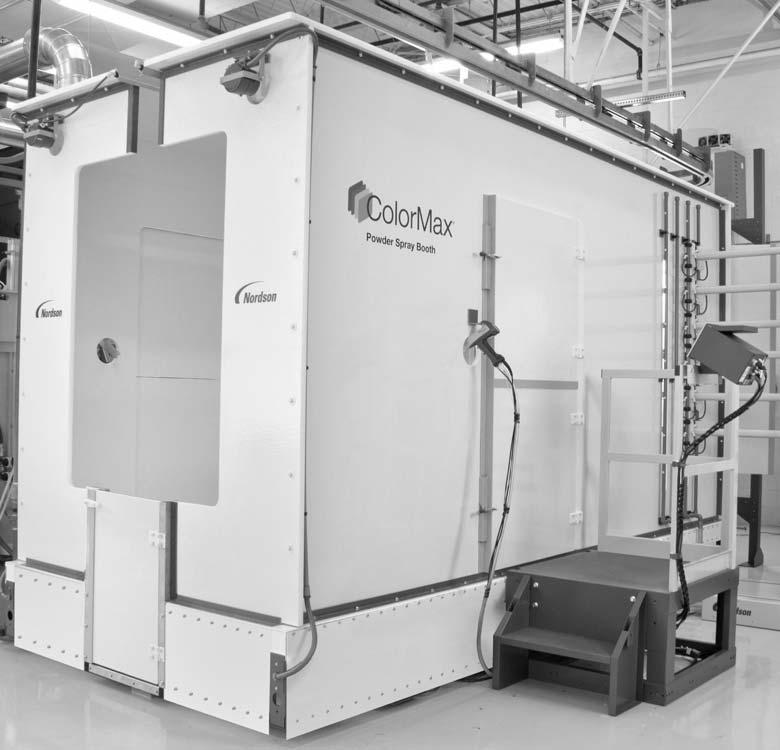
12 2-2 Description System Components Figure 2-1 shows a typical fully equipped ColorMax system. Item Component Function 1 Booth Consists of canopy and base. Contains the oversprayed powder within the system. Refer to page 2-4 for more information. 2 Reclaim System Consists of the cyclone assembly, banjo, duct work, and afterfilter (not shown here). The cyclones separate the oversprayed powder from the air flowing through the booth. The reclaimed powder is pumped back to the feed center. Refer to page 2-6 for more information. 3 Encore Feed Center Consists of an enclosure, sieve, and powder lances and pumps, and purge manifolds. Conditions virgin and reclaimed powder, fluidizes the powder, and pumps it to the spray guns. Refer to page 2-8 for more information. 4 Utility Deck Provides a platform for the major components of the system, and houses wiring and air hoses and tubing, valves and regulators, powder hoses, and gun cables. Shipped pre-plumbed and wired for quick system installation. 5 Main Electrical Control Panel Houses the system operator controls, PLC, and Variable Frequency Drives (VFDs) for the gun movers. Refer to page 2-15 for more information. 6 Gun Movers and Gun Blow-Off Optional equipment. The spray guns can be mounted on fixed stands, oscillators, or reciprocators. These devices can be mounted on automatic or manual positioners. Refer to page 2-10 for more information. 7 Powder Application Equipment Optional equipment. Typically consists of automatic and manual spray guns and controllers. The Nordson icontrol 2 system controls both the automatic spray guns and automatic gun movers (positioners and reciprocators). Refer to the manuals supplied with your system components for information on setup and operation. Not Shown Not Shown Afterfilter icontrol 2 Houses the system exhaust fan, along with cartridge filters that separate the waste powder from the air flow, and final filters that clean the air before returning it to spray room. Refer to page 2-11 for more information. Controls gun triggering and spraying, and gun movers such as in/out positioners and reciprocators. The system uses signals from conveyor encoders, photo eyes, light curtains, and proximity sensors to identify and track the movement of parts through the spray booth, and to control the spray guns and gun movers. Refer to the operator manual for more information.

13 Description Figure 2-1 ColorMax 2 System Components
14 2-4 Description Booth Figure 2-2 shows the exterior and interior components of a typical ColorMax powder spray booth. Item Component Function 1 Conveyor slot and air knife The conveyor slot allows the part hangers to pass completely through the canopy. Compressed air flowing from the air knife prevents sprayed powder from escaping from the conveyor slot. 2 Fire detector heads Continuously monitor the interior of the booth. If an electrical spark or flame is detected, the fire detection system shuts down the entire system. The system controller is typically mounted on the side of the main electrical control panel, or close to it. 3 Canopy Contains the powder within the booth. Can be made from Nordson Apogee panels or polypropylene. The canopy requires periodic conditioning and should not be touched with bare hands to preserve its ability to shed powder. 4 Base Provides the platform for the canopy and includes the floor duct through which the air flows on its way to the cyclones. 5 Manual spray gun operator doors Provides access to the booth for the manual spray gun operators. 6 Operator platforms Provide operators with access to the booth. Manual gun controllers are typically mounted on the platform railings. 7 Booth doors Provide a way to close off the end of the booth and prevent powder from escaping when blowing off the interior of the booth during color changes and routine cleaning. 8 Vertical riser door Provides access to the riser that routes the air flowing through the booth into the cyclone for cleaning and inspection. 9 AeroDeck Act as dampers to prevent the air flowing into the riser inlet from drawing the powder sprayed by the automatic guns away from the parts moving through the booth. Air is pulsed across the AeroDecks by the air knife running down the center of the decks to keep powder from accumulating on top of them. 10 Floor blow-offs Blow the powder off the floor and into the floor duct to prevent accumulations. The blow-offs are pulsed in a repetitive pattern, one section at a time, to keep air consumption to a minimum. 11 Gun blow-off manifolds Distribute the gun blow-off air to the blow-off nozzles. 12 Gun blow-off nozzles Blow off the exterior of the guns as they are retracted from the booth during the color change sequence. There are 4 nozzles for each gun.
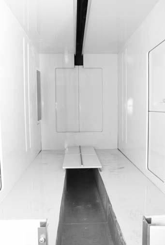
15 Description Figure 2-2 Booth Components
16 2-6 Description Reclaim System Figure 2-3 shows the components of a typical ColorMax reclaim system. Item Component Function 1 Dual cyclone Reclaims usable powder from the air flowing through them. Inside the cyclones, the air swirls around and slows so the larger and heavier powder particles fall to the bottom, into the transfer pan. The fine powder dust stays suspended in the air flow and is carried through the ductwork to the afterfilter. 2 Lower section of cyclone Allows the interior of the cyclones to be cleaned thoroughly during color changes. The lower section is hinged so that it swings up and mates with a cleaning port that is connected to the afterfilter ductwork. 3 Transfer pan Collects and fluidizes the reclaimed powder so the transfer pump can pump it back to the feed center to be sieved and re-used. It contains a porous membrane that diffuses low pressure compressed air into the powder to fluidize it The transfer pan is hinged so it can be opened and cleaned thoroughly during color changes. 4 Transfer pump Pumps the reclaimed powder back to the feed center. The pump is a Nordson High Capacity HDLV pump with purge capability. 5 Cyclone cleaning port Mates with the lower cyclone section when it is swung open. The port maintains an air flow through the lower section while the operator cleans the interior. The port duct is connected to the afterfilter duct work so that waste powder flows directly to the afterfilter. 6 Slide gate Allows air to be pulled through the lower cyclone section and cleaning port when open. Close when not cleaning the lower section. 7 Banjo and afterfilter duct Conveys air and waste powder to the afterfilter from the cyclone. A pneumatically operated slide gate in the duct closes if a fire is detected in the booth to prevent it from spreading to the afterfilter.


17 Description Figure 2-3 Common Reclaim Components
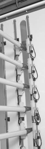
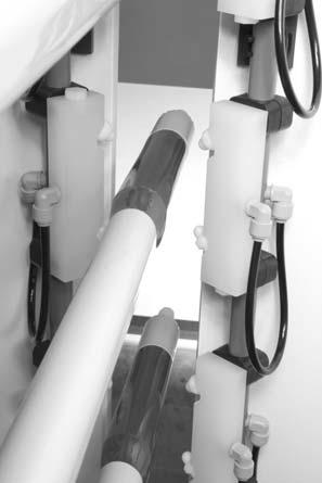
18 2-8 Description Feed Center Figure 2-4 shows the components of the Encore Feed Center. Refer to the feed center manual for additional information and parts lists. Item Component Function 1 Operator control panel Houses electrical and pneumatic controls for the feed center and system. 2 Lance purge regulator Adjusts the lance purge air pressure. 3 Fluidizing air regulator Adjusts the fluidizing air for the hopper or lance. 4 Blow gun Used to blow off the components of the feed center. 5 Level sensors Detect powder levels in hopper or box. When powder level falls below end of sensor, either an alarm is activated or the virgin powder transfer pump is turned on to add more powder to the system, depending on the system configuration. 6 Powder lances Function as pickup tubes so that the pumps mounted on top of the lances can draw powder out of the hopper or box and deliver it to the spray guns. The lances are mounted on the lift assembly. The lances shown are equipped with optional fluidizing bars for use with powder boxes and optional hose manifolds. 7 Powder hopper (optional) Contains and fluidizes the power supply. A porous membrane in the bottom diffuses low pressure compressed air into the powder so that it behaves like a fluid. 8 Vibrating table (vibrator motor is optional) Supports the powder hopper or box, vibrates to fluidize the powder supply. Normally turned on only when powder boxes are used instead of hoppers. 9 In-line powder pumps Pump the powder out to the spray guns. 10 Sieve Vibrates to screen reclaimed and virgin powder before delivering it to the powder hopper or box. Can be fitted with a ultrasonic screen for higher throughput if needed. 11 Lift assembly Consists of a carriage, vertical slide, and pneumatic cylinder. The lances are mounted on the carriage. The cylinder moves the lances up and down. Proximity switches on the cylinder are positioned to stop the lances at different positions depending on the powder source selected by the operator. 12 Disconnect switch Turns on and off power to the feed center controls. Not Shown Not Shown Purge manifold and clamping cylinder Duct damper Located below the vibrating table. During a color change, the lances are lowered onto the purge manifold, where they are clamped in place before the lance and gun purge starts. Located on top of the exhaust duct transition. Opened and closed with a pneumatic cylinder. Controlled by a switch on the operator panel. In Auto mode, when a color change is initiated, the damper is automatically opened to contain the powder within the feed center. When the color change is complete, the damper is partially closed since full flow is not required during normal operation. The operator can also open the damper manually as desired.

19 Description Figure 2-4 Encore Feed Center Components (shown with optional hose manifolds on lances)


20 2-10 Description Automatic Gun Movers/Gun Blow-Off Component Positioners Oscillators or Reciprocators Gun Blow-Off System NOTE: Gun movers are optional. If they are not used, then the spray guns are mounted on fixed stands. Description Move the spray guns into or out of the canopy. The positioners can be manually operated or electrically driven automatic devices. Automatic positioner movement is controlled by the Nordson icontrol system or Axis Controller. During production, the positioners maintain the set gun-to-part distance settings, following the contours of the parts. Positioners move the guns horizontally. Applications may require vertical positioners. Move the spray guns in repetitive or variable patterns for thorough part coverage; position spray guns between blow-off nozzles during color changes. Blow powder off the spray guns as they are retracted out of the booth during the first part of a color change sequence. The nozzles are supplied with air by manifolds located in the booth base. Blowoff Manifolds and Nozzles Automatic Guns Oscillator (or Reciprocator) Positioner Figure 2-5 View of Positioner and Oscillator with Gun Blow-Off System
21 Description 2-11 Afterfilter Figure 2-6 shows a typical afterfilter assembly. The afterfilter houses an exhaust fan that draws air through all booth openings to contain sprayed powder within the system and convey the overspray into the cyclone for reclaim and re-use. The powder dust not reclaimed by the cyclones is filtered out of the air by the cartridge filters and final filters in the afterfilter. Table 2-1 Afterfilter Components Item Component Description 1 Final Filters Remove any remaining fine powder particles from the air before returning it to the spray room. 2 Fan/Motor Assembly Creates and maintains the air flow into the booth and feed center, through the cyclones and ducts, into the afterfilter, and back into the spray room. 3 Waste Hoppers Collect powder particles that are blown off the cartridge filters. 4 Fluidizing Plates Fluidize the powder in the waste hoppers, allowing the powder to be pumped out of the waste hoppers. 5 Intake Duct Brings powder-laden air from the cyclones to the afterfilter. 6 Afterfilter Panel Contains the pulse timer panel, PULSE ON DEMAND switch, and differential pressure switches and gauges. Refer to Afterfilter Panel for more information. 7 Cartridge Filters Filter powder particles out of the air flow through the filter media and into the fan section. 8 Pulse Valves Periodically send pulses of air through the cartridge filters to blow off powder collected on the outside of the cartridges. 9 Pulse Air Manifolds Distributes compressed air to the pulse valves. 10 Pulse Valve Solenoid Boxes Signal the pulse valves to open based on settings made in the pulse valve timer panel. NOTE: The afterfilter may have either deflagration vents or an explosion suppression system. Contact your Nordson representative for information about explosion venting or suppression equipment. Afterfilter Operation See Figure 2-6. Powder is conveyed through the intake duct (5) into the collector section, where powder collects on the external surfaces of the cartridge filters (7). The air passes through the cartridge filters and flows up into the final filter section, through the fan (2) and final filters (1), and back into the spray room. The pulse valves (8) periodically release large volumes of compressed air into the centers of the cartridge filters, blowing the accumulated powder off the filters. Pulsing is controlled by the pulse valve timer in the afterfilter panel (6), which allows you to set both the time between pulses (delay) and the length (duration) of the pulse.
22 2-12 Description Figure 2-6 Afterfilter Operation Front and Side Views The PULSE ON DEMAND switch on the afterfilter panel allows the operator to set cartridge pulsing to be either continuous or on-demand: CONTINUOUS: Cartridges are pulsed at operator-specified intervals set at the pulse valve timer. ON-DEMAND: Cartridges are pulsed when the cartridge filter differential pressure switch detects a pressure drop across the cartridge filters of 6.5-in. water column (wc). Pulsing stops when the pressure drops below 6.5 in. The powder blown off the cartridge filters is unusable, primarily because most of the particles are too small to hold an electrostatic charge. The powder falls into the waste hoppers (3) in the bottom of the collector section. The waste hoppers are equipped with fluidizing plates (4), which diffuse air into the powder so that it will flow easily when pumped out of the hoppers by transfer pumps. The final filter differential pressure switch monitors the pressure drop across the final filters. At 2.5-in. wc, a red warning light on the system control panel lights. At 3-in. wc, the entire system shuts down. Typically, the afterfilter is equipped with quick-acting explosion and fire suppression systems. These are not shown here.
23 Description 2-13 Control Panels Refer to the following tables for a description of typical system controls. The contents and locations of the control panels vary depending on the system configuration and options installed. Encore Venturi Feed Center Control Panel See Figure 2-7. Table 2-2 Powder Feed Center Control Panel Control Function 1. Damper Selection Left: Manual mode Damper is open for high flow. Right: Auto mode Damper is partially closed during normal operation, open during color change. 2. Bulk Feed Pump Turns on and off the virgin powder transfer pump. Used when system is equipped with a bulk feed system. When on, the pump is turned on and off automatically as needed to satisfy the level sensor on the lance assembly. 3. Reclaim Powder Transfer Pump Turns on and off the reclaim powder transfer pump. When on, the pump operates continually. 4. Sieve Control Turns sieve vibrator motor on and off. 5. Color Change Enable Starts color change sequence. If operator platform is equipped with an Ancillary Equipment Clean Cycle button, lances are automatically raised out of hopper or box. If not, then starts external gun blow off. 6. Emergency Stop Shuts down powder coating system. 7. Table Vibrator Turns table vibrator motor on and off. 8. Purge Selection Left: Start internal gun purge cycle. Center: Off Right: Start transfer pump purge cycle. 9. Lance Lift Raises and lowers lance assembly. 10. Powder Source Selects hopper or box, controls where lances stop when lowered into powder. Select 11. Color Change Indicator Light (Green) Off: Color change cycle is disabled Blinking: In color change cycle. On: Color change automatic operations complete.
24 2-14 Description Figure 2-7 Powder Feed Center Controls

25 Description 2-15 Main Electrical Control Panel See Figure 2-8. Your system control panel may be different. Table 2-3 Main Electrical Control Panel Functions Component Description 1. SYSTEM START Turns on system power. Lights green when on. 2. SYSTEM STOP Turns off power to the system control panel. 3. SYSTEM READY Lights green when the SYSTEM START button is pressed, the duct gate is fully open, and all interlocks are satisfied. 4. AFTERFILTER FAN Starts the afterfilter exhaust fan and enables all other system functions. START 5. AFTERFILTER FAN STOP Stops the afterfilter exhaust fan and disables system functions. 6. FINAL FILTER WARNING Lights if final filters start clogging and the warning level on the differential pressure switch is reached. 7. FLOOR CLEAN Turns on and off canopy floor blow-off pulsing. 8. OSCILLATOR #1 Turns on and off Oscillator #1 motion. START and STOP 9. OSCILLATOR #2 START and STOP Turns on and off Oscillator #2 motion. 10. OSCILLATOR #1 Regulates oscillator speed from Minimum to Maximum. and 2 SPEED 11. ANCILLARY EQUIPMENT CLEAN and RESET Lights amber when the ancillary equipment clean function is active. Turns the ancillary clean function to OFF when pushed ANC EQUI RESET Figure 2-8 Main Electrical Control Panel
26 2-16 Description Typical System Options Refer to the manuals shipped with optional equipment for more information, or contact your Nordson Corporation representative. Air Dryer Equipment Spray Gun Oscillators or Reciprocators Powder Drum Unloaders Fluidizing Hopper Part Identification and Spray Gun Triggering Systems Table 2-4 Typical System Options Description Removes moisture from the system air supply. Most systems use regenerative-desiccant or refrigerated air dryers. Move the spray guns in repetitive vertical patterns for thorough part coverage. Oscillators are typically controlled from the system control panel. Reciprocators are controlled by a Nordson icontrol system, Axis controller, or PLC. Transfer virgin powder from shipping boxes, drums, or bags to the powder feed center. Plastic boxes with fluidizing plates and pans, which diffuse low pressure air into the powder so it can be pumped out of the hoppers and out to the spray guns. Identify and track parts on the conveyor line and control automatic spray gun movement, triggering, pump and gun air, and electrostatic voltage. The Nordson icontrol system provides all these functions. Roll-On/Roll-Off System Roll-on/roll-off systems move the booth offline for color change, cleaning, and maintenance. In roll-on/roll-off systems, the entire system, including the cyclone, is mounted on a platform equipped with casters and motor drives. The casters ride on rails installed in the spray room floor. The motor drives move the platform online and offline. The cyclone is disconnected from the afterfilter before the move, then re-connected when the move is completed. Booth movement is controlled by online and offline end-of-travel limit switches. Operator controls consist of switches on the system control panel or a pendant.
27 Operation 3-1 Section 3 Operation WARNING: Allow only qualified personnel to perform the following tasks. Follow the safety instructions in this document and all other related documentation. Introduction The PLCs in the powder feed center and the main electrical control panel control the automatic processes in a typical system. The PLCs are typically programmed by your Nordson application engineer to suit your application requirements. Spray gun triggering and the movement of positioners and reciprocators are typically controlled by a Nordson icontrol Integrated Control system. Refer to the icontrol manuals for instructions on configuration, programming, and operation. CAUTION: Before starting up your powder coating system for the first time, perform the Initial Canopy Conditioning procedure in Maintenance. The inside surfaces of the canopy must be clean, free of oils, and dry. A clean canopy prevents powder from sticking, and allows for fast color changes. Do not touch the inside surfaces of the canopy with bare hands if possible. Wear clean cotton gloves when working in the canopy interior. NOTE: Before starting your system for the first time, review and adjust if necessary your feed center PLC function settings, level sensor functions, and air pressure settings. These are described in the Setup section of the feed center manual.
28 3-2 Operation Typical Operating Settings The settings listed here are approximate. You may need to adjust these settings to obtain the desired results. Operating Air Pressures Table 3-5 Typical Operating Air Pressures Air Pressure Setting Input (System) 7 bar (100 psi) Cartridge Filter Pulse (Afterfilter) 4 bar (60 psi) Waste Hopper Fluidizing 1 bar (15 psi) (Afterfilter) AeroWash 5.5 bar (80 psi) Floor Blow-Off Bleed Air 2.8 bar (40 psi) Floor Blow-Off Pulse Air 3.4 bar (50 psi) Purge Air (Feed Center) 6.2 bar (90 psi) Feed Hopper Fluidizing Air bar (5 10 psi) Lance Fluidizing Air bar (5 10 psi) Timer Board Settings Table 3-6 Typical Timer Board Settings Timer Setting Afterfilter Cartridge Filter Pulsing On Time (Duration) 0.07 seconds Off Time (Delay) seconds


29 Operation 3-3 Booth Control Functions The booth functions are controlled by a PLC inside the main electrical control panel. The following function values are programmed into the controller at the factory and can be adjusted as needed for the application. Table 3-7 Powder Feed Center Function Settings Screen Function Description Default SCREEN 1 Welcome Screen Displays program reference number, program description, program version number and last edit date. N/A SCREEN 2 Blow-Off Zone Shows the number of blow off zones in the system. This can be adjusted from 1 to 8. 6 SCREEN 3 Blowoff Zone Settings, Zones 1 4 Sets the blow-off zone ON time for zones seconds (150ms) SCREEN 4 Blow-Off Zone Settings, Zones 5 8 Sets the blow-off zone ON time for zones seconds (150ms)


30 3-4 Operation Screen Function Description Default SCREEN 5 Blow-Off Delay Sets the delay time between each floor blow-off actuation seconds NOTE: If changed, please turn the FLOOR CLEAN SWITCH on the MECP enclosure door to OFF, then ON to load the new value. SCREEN 6 AeroDeck ON Time The AeroDeck cleaning valve will activate after zones 2, 4, 6, and 8 turn off. The ON time will be timed in accordance with the blow-off delay time stetting seconds NOTE: This value should always be at least 4 seconds less than the delay value in Screen 5. SCREEN 7 After Filter Vibrate and Fluidizing Duration Sets the duration time for the after filter vibrate and fluidizing function seconds SCREEN 8 After Filter Vibrate and Fluidizing Cycle Delay Sets the delay time for the after filter vibrate and fluidizing cycle. 10:00 minutes


31 Operation 3-5 Screen Function Description Default SCREEN 9 Status Screen 1 This is a status screen only with no adjustable parameters. N/A The screen displays the next floor blow-off zone, current blow-off delay time remaining, AeroDeck ON time remaining, and AeroDeck OFF time remaining. SCREEN 10 Status Screen 2 This is a status screen only with no adjustable parameters. N/A The screen displays the programmed AeroDeck ON time and the calculated OFF time. This screen is updated if the user values from Screen 5 and 6 are changed, and the FLOOR CLEAN selector switch is toggled OFF then ON.
 or DOWN ( ) arrow keys. 3. While on the selected screen, press and hold the ESC key.")
32 3-6 Operation Changing Function Values Open the main electrical control panel door to access the PLC. NOTE: These instructions are also reproduced on a label on the inside of the control panel door. Figure 3-1 Feed Center PLC Interface 1. Press the ESC key to begin search. 2. Find the function screen to be changed by pressing the UP ( ) or DOWN ( ) arrow keys. 3. While on the selected screen, press and hold the ESC key. A cursor will appear. 4. Use the LEFT ( ) and RIGHT ( ) arrow keys to position the cursor on the value to be changed. 5. Press the OK key to highlight the value. 6. Use the LEFT ( ) and RIGHT ( ) arrow keys to select the correct units (xx:xx) column, and then the UP ( ) and DOWN ( ) arrow keys to change the value. 7. Press the the OK key to enter the value. 8. Make additional changes to the same page by moving the cursor as described in steps When data changes to the page are complete, press the ESC key twice.
33 Operation 3-7 Startup Use the following procedure to start up the system on a daily basis. NOTE: These procedures assume that the system has been cleaned. 1. Turn the main electrical control panel, feed center, and afterfilter control panel disconnect switches to the ON position. 2. If applicable, move the system into the on-line position. Refer to Booth Moving in this section for more information. 3. Refer to page Press the SYSTEM START button on the system control panel. The button lights. The safety gate (in the duct between the cyclones and the afterfilter) opens. When the gate is fully open and all interlocks are satisfied, the SYSTEM READY indicator lights and the system is ready to start. 4. Press the AFTERFILTER FAN START button on the system control panel. The fan starts and the afterfilter cartridge filters are pulsed automatically. 5. Turn the FLOOR CLEAN switch to the ON position. 6. Select the powder source (hopper or box) on the feed center control panel. 7. Fill a feed hopper 2/3 full of powder, or open a powder box. 8. Raise the lance assembly and center the powder source under the lances. 9. Lower the lances into the powder. The lance will stop at a position determined by the powder source selection. 10. Turn on the vibrator table if the powder source is a box. 11. Adjust the fluidizing air pressure, using the regulator on the side of the feed center. The powder should be gently boiling without geysering out of the powder source. Allow the powder to fluidize for several minutes before starting production. 12. Turn on the powder sieve.
34 3-8 Operation 13. Turn on the reclaim transfer pump. 14. If a bulk unloader is used, turn on the virgin powder transfer pump. 15. Turn the Damper switch to the Automatic position. WARNING: Make sure all personnel are clear of the oscillators or reciprocators and spray guns before turning them on. Failure to observe this warning could result in equipment damage and injury to personnel. 16. Turn on the oscillators or reciprocators from the system control panel. 17. Turn on the manual spray gun controllers and the automatic gun controller, if not already on. 18. Make sure the part ID system is powered and working properly. NOTE: Before spraying powder, wait several minutes for the powder in the feed source to fluidize. When properly fluidized, the powder will be gently boiling. Adjust the fluidizing air pressure as needed. 19. Start the conveyor, hang parts on it, and start production. Refer to your spray gun controller manuals for adjustments to the spray settings. NOTE: It is important that the inside surface of the canopy is not touched by bare hands. Skin oils and other contaminants will affect the ability of the canopy to shed powder. Operators should wear cotton gloves when working with the canopy.
35 Operation 3-9 Ancillary Equipment Clean Function See Figure 3-1. The Ancillary Equipment Clean and Reset control is located on the non-cyclone side manual platform. This function allows the manual station operator to initiate the first part of the color change cycle, or the ancillary clean mode, without disrupting work flow. As the last part to be coated passes the automated coating equipment, the non-cyclone side operator can press the START ANCILLARY EQUIPMENT CLEAN CYCLE button to initiate this mode. The operator can then complete the task of touching up the final part as the automatic equipment clean cycle is running. A corresponding indicator and reset button located at the system panel will turn amber as an indication that the mode is activated. This reset button can be pushed at any time during the clean cycle to turn the function off. See Figure 2-8. At the conclusion of the ancillary equipment clean cycle, the color change switch located the the feed center panel can be turned to the ON position to complete the color change sequence.. Figure 3-1 Ancillary Equipment Clean Cycle Button Box Color Change Procedures Color change procedures vary depending on the type of application equipment and feed center included in the system. To perform a color change most efficiently, it is recommended that two trained operators be present. The operators are responsible for cleaning the following items: 1. Cyclone side operator: Powder feed center and cyclones 2. Non-cyclone side operator: Interior of booth canopy and cyclones The two operators tasks should be performed at the same time unless otherwise noted. Refer to the foldouts included as a supplement to this manual for step-by-step procedures. Note that the procedures are recommendations only and can be modified as desired.
36 3-10 Operation Powder Level Sensor Operation The lance assembly lowers as the powder level falls. When the level sensor senses no powder, the sensor activates either a low-powder alarm or starts the bulk feed transfer pump to add virgin powder to the system. There are two level sensors. The position of one should be set for boxes, the other for hoppers. When the lance is lowered into the powder, it will stop at the position set on the lance cylinder proximity switches for the selected powder source. The level sensor positions should be set to signal for new powder or a low powder alarm when the powder height is the desired distance above the end of the lances. Refer to the Encore Powder Feed Center manual for more information. Booth Moving Perform this procedure to move the system online or offline. NOTE: Disregard this procedure if your system is not equipped with a roll-on/roll-off system. 1. From the Main Menu, touch the Booth Move button. 2. Touch the Exhauster Stop button. The afterfilter exhaust fan stops. 3. Touch the Duct Lifter Open button. The cyclones disconnect from the afterfilter inlet duct. 4. When BOOTH MOVER READY is displayed on the booth moving menu, press the BOOTH MOVER ENABLE button on the system control panel. The booth mover buzzer sounds and the pendant button is enabled for three minutes. 5. Visually check the area around the booth for obstructions. Clear the area of all obstructions and personnel. 6. Press the pendant button to move the booth to the desired position. The booth moves as long as the button is held down. The booth stops moving when either you release the button or the booth reaches either the online or offline position. 7. When either ONLINE READY or OFFLINE READY is displayed on the booth moving menu, touch the Duct Lifter Close button. The cyclones connect to the afterfilter inlet duct. 8. When EXHAUSTER READY is displayed on the booth moving menu, touch the Exhauster Start button. The afterfilter exhaust fan starts.
37 Operation 3-11 Shutdown Use the following procedure to shut down the system. 1. Move the booth offline, if desired. Refer to Booth Moving. 2. Clean the system by performing the color change process, but do not install a new powder source. Refer to the Color Change section for more information. 3. Press the SYSTEM STOP button. All of the motors in the system turn off. NOTE: If you are shutting down the system for a short break in production, do not perform step If you will be shutting down the system for maintenance, repair, or an extended period of time, perform these steps: a. Press the SYSTEM STOP button on the system control panel. b. Turn the disconnect switches on the powder feed center, main electrical control panel, and afterfilter control panels to the OFF position.
38 3-12 Operation
39 Maintenance 4-1 Section 4 Maintenance WARNING: Allow only qualified personnel to perform the following tasks. Follow the safety instructions in this document and all other related documentation. Initial Canopy Conditioning Perform this procedure on new canopies before initial startup. This procedure removes any oils or other contaminants from the canopy, making the canopy easy to clean and reducing the potential for contamination of reclaimed powder. Required: Acetone or 80%+ isopropyl alcohol, mild dishwashing detergent, clean water, 5 gallon buckets, pre-washed 100% cotton rags, clean hand sponges and sponge mop. NOTE: Rags used for cleaning must be washed before use to remove sizing and starches which would be transferred to the canopy surfaces, degrading the ability of the canopy to shed powder. 1. Wipe down entire canopy with acetone or isopropyl alcohol and pre-washed, 100% cotton rags. 2. Fill two clean buckets with water. 3. Put 2 3 drops of mild dish washing detergent into one of the buckets. This will be the soap bucket. 4. Soak and wring out a hand sponge or a sponge mop in the soap bucket. Wipe down the entire inside of the canopy, frequently wringing out the sponge in the rinse bucket and then re-soaping the sponge in the soap bucket. A continuous wet surface is not necessary, so do not be concerned if some surfaces air-dry prior to next step. You must make sure that the soap solution contacts all surfaces. 5. Empty the buckets, rinse them, and repeat steps 1 3, for a total of two wash cycles. 6. Empty the buckets and rinse them. Fill the buckets with clean water and rinse the entire inside of the canopy, frequently wringing out the sponge in the rinse buckets. 7. Repeat step 5 two more times, for a total of three rinse cycles, then allow the canopy to completely dry before spraying powder. NOTE: It is important that the inside surface of the canopy is not touched by bare hands. Skin oils and other contaminants will affect the ability of the canopy to shed powder during blowoff. Operators should wear cotton gloves when working with the canopy.
40 4-2 Maintenance Daily Maintenance Perform these procedures daily to keep your system clean and functioning properly. System Cleaning Perform this procedure daily. WARNING: Wear an approved respirator and safety glasses or goggles when performing maintenance or cleaning operations. Obtain and read Material Safety Data Sheets for each powder used. 1. Perform all procedures in the Color Change section, stopping at loading new powder into the feed center and spraying new powder. 2. After the spray guns are purged and blown clean, wipe down the spray guns with clean cotton cloths. Clean the nozzles and replace any worn parts. Refer to the gun manuals for additional maintenance procedures. 3. Remove any powder residue from the booth using an air-powered vacuum with a soft brush attachment. Wipe down all surfaces with a damp, lint-free cloth (do not use tack cloths). NOTE: It is important that the inside surface of the canopy is not touched by bare hands. Skin oils and other contaminants will affect the ability of the canopy to shed powder during blowoff. Operators should wear cotton gloves when working with the canopy. 4. Clean the feed center and wipe down the interior with clean cotton cloths. 5. Clean the floor around the booth. Daily Equipment Maintenance Equipment Flame Detector System Air Dryers Air Velocity Compressed Air Supply Table 4-1 Daily Equipment Maintenance Procedure Check the detector sensors every four hours and clean the lenses, if necessary. Make sure air is being supplied to the sensors. Make sure the detector system is operating properly. Perform any required maintenance as described in your air dryer manual. Measure the air velocity at all booth openings with a velometer. Minimum velocity is 43 m/min (140 fpm). Hold a clean, white cloth under the supply line drop leg and open the drop-leg drain valve. Water, oil, or other contaminants will stain the cloth. Eliminate any source of contamination. Drain the filters and separators and check the filter elements. Check all air pressure regulator settings. NOTE: The air dryer should remain on at all times to prevent moisture from accumulating in the compressed air system. Continued...
41 Maintenance 4-3 Equipment Afterfilter Cartridge Filters and Housings Final Filter Housing and Fan Oscillators, Reciprocators, and In/Out Gun Positioners Powder Spray Guns Powder Pumps Sieve Reclaim and Virgin HDLV Transfer Pumps Afterfilter Transfer Pumps Workpiece, Equipment, and Conveyor Grounds Procedure Pulse the cartridge filters to clean them. With the exhaust fan operating, check the cartridge filter differential pressure gauge. It should read between 4- and 6-in. wc. Check the pulse valve timing to make sure that the cartridge filters are being pulsed often enough to prevent clogging. If pulsing the filters does not clean them enough to bring down the pressure, then the filters have reached the end of their lives and must be replaced. With the exhaust fan operating, check the final filter differential pressure gauge. It should read between 1- and 2.5-in. w.c. If the differential pressure exceeds 3 w.c., that system will shut down, as the pressure indicates that the final filters are clogged, most likely by the failure of a cartridge filter. If this happens, replace the final filters. Check the cartridge filters and replace any that have failed. Each shift, make sure the oscillators and reciprocators are stroking smoothly and at the proper speed. Make sure the positioners are moving smoothly. Lubricate the gun movers and make repairs and adjustments as necessary. Refer to the gun mover manuals for instructions. Clean the spray guns according to the instructions in their manuals. Disassemble and clean the pump blocks, venturi throats and throat holders. Replace worn parts. Remove and clean the screen. Replace the screen if it is damaged. Check the rubber seals. Replace any damaged or worn parts. Inspect the pinch valve body for signs of powder leakage. If you see powder in the pinch valve body or stress cracks in the pinch valves, replace the pinch valves. Refer to the pump manual for long term maintenance and repair procedures. Disconnect the transfer hoses from the pumps. Blow out the powder from the hoses with compressed air. Remove the transfer pumps from the adapters. Blow out the adapters and pickup tubes. Disassemble the pumps. Clean the parts with a low-pressure air gun and a clean cloth. Replace any worn or damaged parts. WARNING: An ungrounded or poorly grounded workpiece, hanger, conveyor, or other equipment can cause electrical arcing. If arcing is observed, shut down the system immediately. Correct the cause before resuming operations. Failure to observe this warning could result in a fire or explosion, causing property damage and possible personal injury or death. Make sure all workpieces are grounded through the hangers and conveyor. The resistance between the workpieces and the hangers, and the hangers and ground, must be less than 1 megohm. Use a megohm meter to check resistances. You will get better transfer efficiency and workpiece coverage at 500 ohms or less. Clean the hangers regularly.
42 4-4 Maintenance Weekly Maintenance Equipment Booth Enclosure Differential Pressure Gauges Powder Spray Guns and Cables Powder Pumps and Feed Hoses Table 4-2 Weekly Maintenance Procedure Clean the booth exterior, all attached equipment, and the spray room. Check the canopy for damage and dirt. Clean as necessary. Refer to the Booth Canopy Conditioning procedure on page 4-5. Observe and record the differential pressure gauge readings. Cartridge Filters Pressure Drop: in. wc Final Filters Pressure Drop: in. wc If the pressure drop across the cartridge filters exceeds 6.5-in. wc, the filters are clogged. If the pressure drop across the final filters exceeds 2.5-in. wc, the final filter warning light on the system control panel will light. At 3-in. wc the system will shut down. Clean the spray guns. Perform electrostatic resistance checks as described in the spray gun and control unit manuals. Purge the lance assemblies. Disassemble the pumps and clean the venturi throats and nozzles. Replace any worn or damaged parts. Blow out the feed hoses with compressed air. Replace damaged or clogged hoses. Monthly Maintenance Equipment Afterfilter Waste Hoppers Air Dryer Electrical Connections Gaskets Fan and Roll-On/Roll-Off System Bearings Roll-On/Roll-Off Wheels Equipment Grounds Table 4-3 Monthly Equipment Maintenance Procedure Empty the afterfilter waste hoppers monthly. Refer to Emptying the Waste Hoppers for instructions. Check the air dryer operation. Refer to your air dryer manual for maintenance procedures and schedules. Check all terminal blocks and junction boxes for loose wires. Tighten any loose connections and inspect the system wiring. Replace any damaged wires. Inspect all gaskets and seals for damage. Replace them if they are damaged. Every six months, lubricate the fan bearings and all motor bearings with two shots of No. 2 lithium grease from a grease gun. Lubricate the flanged wheel bearings with two shots of white lithium grease every six months. WARNING: Ungrounded or poorly grounded equipment can cause electrical arcing. If arcing is observed, shut down the system immediately. Correct the cause before resuming operations. Failure to observe this warning could result in a fire or explosion, causing property damage and possible personal injury or death. Check all equipment grounds. Repair or replace unconnected or damaged ground cables.
43 Maintenance 4-5 Booth Canopy Conditioning Perform this procedure every six months or whenever it becomes difficult to blow powder off the canopy surface. Conditioning keeps the canopy easy to clean and reduces the potential for contamination of reclaimed powder. NOTE: To remove impact-fused powder, perform the initial canopy conditioning procedure on page Fill two clean buckets with water. 2. Put 2 3 drops of mild dish washing detergent into one of the buckets. This will be the soap bucket. 3. Soak and wring out a hand sponge or a sponge mop in the soap bucket. Wipe down the entire inside of the canopy, frequently wringing out the sponge in the rinse bucket and then re-soaping the sponge in the soap bucket. 4. Empty the buckets, rinse them, and repeat steps 1 3, for a total of two wash cycles. 5. Empty the buckets and rinse them. Fill the buckets with clean water and rinse the entire inside of the canopy, frequently wringing out the sponge in the rinse buckets. 6. Repeat step 5 two times, for a total of three rinse cycles. Allow the canopy to completely dry before resuming spray operations. NOTE: It is important that the canopy is not touched by bare hands. Skin oils and other contaminants will affect the ability of the canopy to shed powder during blowoff. Operators should wear cotton gloves when working with the canopy.
44 4-6 Maintenance Cyclone Cleaning Use the cyclone cleaning media listed in Parts to clean the cyclones and remove impact-fused powder. Results may vary depending on the level of impact fusion. Cleaning durations can be reduced or increased to meet system requirements. 1. Disconnect the transfer hose and fluidizing air tubing from the transfer pan at the bottom of the cyclone. 2. Plug all the tubing and hose connectors in the transfer pan. 3. Close the cyclone access doors, if open. 4. With the exhaust fan running, dump 1 2 cups of cyclone cleaning media into the cyclone inlet duct. 5. Let media clean the cyclones for approximately one hour. This duration can be reduced or increased as needed. 6. Shut down the exhaust fan. 7. Open the transfer pan and remove the remaining cyclone cleaning media. 8. Close the transfer pan. 9. Load a new powder color and reclaim to waste for 1 2 minutes to cleanse the system of the cyclone cleaning media residue.


45 Maintenance 4-7 HDLV Transfer Pump and Transfer Pan Maintenance For more detailed maintenance and repair information, refer to the Prodigy HDLV High-Capacity Pump manual. Component HDLV Reclaim and Virgin Transfer Pumps Maintenance Procedure Daily Inspect the pinch valve body for signs of powder leakage. If you see powder in the pinch valve body or stress cracks in the pinch valves, replace the pinch valves. Pinch Valves Kit Every Six Months or Each Time You Disassemble the Pump Disassemble the pump assembly and inspect the lower Y body and upper Y-manifold for signs of wear or impact fusion. Clean these parts in an ultrasonic cleaner if necessary. NOTE: To reduce downtime, keep a spare upper Y-manifold and lower Y body in stock to install while you are cleaning the other set. Upper Y-Manifold Kit Transfer Pan (Cyclone) Lower Y Body Part Periodically disassemble and clean the transfer pan. Refer to Transfer Pan Cleaning for instructions. NOTE: Required cleaning frequency depends on several factors, including powder type used, color change frequency, and experience. Periodically blow off the fluidizing plate and inspect it for signs of air contamination. If the plate is discolored and appears to be contaminated, replace it. Refer to Transfer Pan Cleaning for replacement instructions. Check your air supply and correct any contamination problems.
Prodigy ColorMax Powder Coating System
 Prodigy ColorMax Powder Coating System Customer Product Manual Issued 6/09 For parts and technical support, call the Industrial Coating Systems Customer Support Center at (800) 433-9319 or contact your
Prodigy HDLV Pump. Customer Product Manual Part A02
 Prodigy HDLV Pump Customer Product Manual Issued 1/07 For parts and technical support, call the Industrial Coating Systems Customer Support Center at (800) 433-9319 or contact your local Nordson representative.
Prodigy HDLV Generation II Pump Panel
 Prodigy HDLV Generation II Pump Panel Customer Product Manual Issued 01/10 For parts and technical support, call the Finishing Customer Support Center at (800) 433-9319. This document is subject to change
RediCoat by Nordson. Hopper and VBF Dolly Systems. Customer Product Manual Part A Issued 10/07
 RediCoat by Nordson Hopper and VBF Dolly Systems Customer Product Manual Part 1082648A Issued 10/07 This document is subject to change without notice. Nordson Corporation Amherst, Ohio USA 2 Table of Contents
Sure-Max Powder Transfer System
 Sure-Max Powder Transfer System Customer Product Manual Issued 7/06 For parts and technical support, call the Industrial Coating Systems Customer Support Center at (800) 433-9319 or contact your local
Prodigy HDLV Pump Manifold and Circuit Board
 Prodigy HDLV Pump Manifold and Circuit Board Customer Product Manual Issued 05/08 For parts and technical support, call the Finishing Customer Support Center at (800) 433-939. This document is available
Encore HD Powder Spray System with Prodigy Pump Cabinet
 Encore HD Powder Spray System with Prodigy Pump Cabinet Customer Product Manual Part 604979-06 Issued 05/8 For parts and technical support, call the Industrial Coating Systems Customer Support Center at
Prodigy Powder Port Feed Center
 Prodigy Powder Port Feed Center Customer Product Manual Issued 2/ For parts and technical support, call the Finishing Customer Support Center at (800) 433-939. This document is subject to change without
Powder Feed Center. Customer Product Manual Part A03
 Powder Feed Center Customer Product Manual Issued 1/09 For parts and technical support, call the Industrial Coating Systems Customer Support Center at (800) 433-9319 or contact your local Nordson representative.
Econo-Coat Manual Powder Spray Gun
 Econo-Coat Manual Powder Spray Gun Customer Product Manual Issued 0/03 For parts and technical support, call the Industrial Coating Systems Customer Support Center at (800) 433-939 or contact your local
Tribomatic II Extended Automatic Powder Spray Gun
 Tribomatic II Extended Automatic Powder Spray Gun Customer Product Manual Issued 7/06 For parts and technical support, call the Industrial Coating Systems Customer Support Center at (800) 433-939 or contact
Tribomatic II Purgeable Automatic Powder Spray Gun
 Tribomatic II Purgeable Automatic Powder Spray Gun Customer Product Manual Issued 4/0 For parts and technical support, call the Industrial Coating Systems Customer Support Center at (800) 4-99 or contact
Encore HD Automatic System Standalone Pump Stand
 Encore HD Automatic System Standalone Pump Stand Customer Product Manual Part 6 0 Issued /7 For parts and technical support, call the Finishing Customer Support Center at (00) 4-99. This document is subject
Excel 3000 Series Powder Coating System
 Excel 3000 Series Powder Coating System Customer Product Manual Part 1095480 02 Issued 1/18 For parts and technical support, call the Industrial Coating Systems Customer Support Center at (800) 433 9319
Vantage Manual Powder Spray Gun
 Vantage Manual Powder Spray Gun Customer Product Manual Issued 04/16 For parts and technical support, call the Finishing Customer Support Center at (800) 433-9319. This document is subject to change without
NVR-Series Vertical Reciprocators
 NVR-Series Vertical Reciprocators Customer Product Manual Issued /6 For parts and technical support, call the Finishing Customer Support Center at (800) 4-99. This document is subject to change without
Envirocoat Series Powder Coating System
 Envirocoat Series Powder Coating System Customer Product Manual Issued 2/11 For parts and technical support, contact your local Nordson representative This document is subject to change without notice.
Big Bag Unloader. Customer Product manual Part Number Issued 07/17
 Big Bag Unloader Customer Product manual Part Number 7580188-01 Issued 07/17 For parts ordering, call the Industrial Coating Systems EU Customer Support Center on 0080070017001 or contact your local Nordson
Versa-Spray IPS Manual Electrostatic Porcelain Enamel Powder Spray Gun
 Versa-Spray IPS Manual Electrostatic Porcelain Enamel Powder Spray Gun Customer Product Manual Issued 11/06 For parts and technical support, call the Industrial Coating Systems Customer Support Center
902 Powder Coating Booth
 902 Powder Coating Booth Customer Product Manual Part For parts and technical support, call the Industrial Coating Systems Customer Support Center at (800) 433-9319 or contact your local Nordson representative.
Spectrum HD Feed Center
 Spectrum HD Feed Center Customer Product Manual Issued 09/18 For parts and technical support, call the Industrial Coating Systems Customer Support Center at (800) 433-9319 or contact your local Nordson
Colormax Powder Coating System Color Change Process
 Nordson Corporation OPERATOR S CARD P/N 1015049B Colormax Powder Coating System Color Change Process Safety WARNING: Allow only qualified personnel to perform the following tasks. Follow the safety instructions
Vantage Modular Gun Control System
 Vantage Modular Gun Control System Customer Product Manual Issued 04/5 For parts and technical support, call the Finishing Customer Support Center at (800) 433-939. This document is available on the Internet
Electrostatic Flux Coating System
 Electrostatic Flux Coating System Customer Product Manual Part NORDSON CORPORATION AMHERST, OHIO USA Nordson Corporation welcomes requests for information, comments and inquiries about its products. General
Versa-Spray IPS Automatic Electrostatic Porcelain Enamel Powder Spray Gun
 Versa-Spray IPS Automatic Electrostatic Porcelain Enamel Powder Spray Gun Customer Product Manual Issued 05/6 For parts and technical support, call the Industrial Coating Systems Customer Support Center
Encore HD and XT Manual Powder Spray System Controller
 Encore HD and XT Manual Powder Spray System Controller Customer Product Manual Issued 04/18 For parts and technical support, call the Industrial Coating Systems Customer Support Center at (800) 433-9319
ColorMax Powder Coating Booth Installation Guide
 ColorMax Powder Coating Booth Installation Guide Customer Product Manual Issued /0 For parts and technical support, call the Finishing Customer Support Center at (800) 433-939. This document is subject
Versa-Spray II Automatic Powder Spray Gun
 Versa-Spray II Automatic Powder Spray Gun Customer Product Manual Issued 05/6 For parts and technical support, call the Industrial Coating Systems Customer Support Center at (800) 433-939 or contact your
Sure Coat Individual Controllers
 Sure Coat Individual Controllers Customer Product Manual Issued 9/03 For parts and technical support, call the Industrial Coating Systems Customer Support Center at (800) 433-939 or contact your local
Prodigy HDLV Pump Generation III, Pump Manifold and Circuit Board
 Prodigy HDLV Pump Generation III, Pump Manifold and Circuit Board Customer Product Manual Issued 3/6 For parts and technical support, call the Finishing Customer Support Center at (800) 433-939. Check
Spectrum VT Feed Center
 Spectrum VT Feed Center Customer Product Manual Issued 06/18 For parts and technical support, call the Industrial Coating Systems Customer Support Center at (800) 433-9319 or contact your local Nordson
Vantage Individual Powder Spray Gun Controller
 Vantage Individual Powder Spray Gun Controller Customer Product Manual Issued 04/15 For parts and technical support, call the Finishing Customer Support Center at (800) 433-9319. This document is subject
Versa-Spray II Automatic Powder Spray Gun
 Versa-Spray II Automatic Powder Spray Gun Customer Product Manual Issued /06 For parts and technical support, call the Industrial Coating Systems Customer Support Center at (800) 433-939 or contact your
Encore HD Pump. For parts and technical support, call the Finishing Customer Support Center at (800)
") Encore HD Pump Customer Product Manual Issued 3/18 For parts and technical support, call the Finishing Customer Support Center at (800) 433-9319. Check http://emanuals.nordson.com/finishing for the latest
Encore HD Pump Customer Product Manual Issued 3/18 For parts and technical support, call the Finishing Customer Support Center at (800) 433-9319. Check http://emanuals.nordson.com/finishing for the latest
Prodigy Automatic Powder Spray Guns
 Prodigy Automatic Powder Spray Guns Customer Product Manual Part 1054075-09 Issued 8/18 For parts and technical support, call the Industrial Coating Systems Customer Support Center at (800) 433-9319 or
Rhino SD3/XD3 Air Motor
 Rhino SD3/XD3 Air Motor Customer Product Manual Issued 6/18 For parts and technical support, call the Industrial Coating Systems Customer Support Center at (800) 433-9319 or contact your local Nordson
Prodigy Robot Gun. For parts and technical support, call the Finishing Customer Support Center at (800)
") Prodigy Robot Gun Customer Product Manual Issued 3/14 For parts and technical support, call the Finishing Customer Support Center at (800) 433-9319. This document is subject to change without notice. Check
Prodigy Robot Gun Customer Product Manual Issued 3/14 For parts and technical support, call the Finishing Customer Support Center at (800) 433-9319. This document is subject to change without notice. Check
EcoLiner Compound Gun
 EcoLiner Compound Gun Customer Product Manual Issued 3/06 For parts and technical support, call the Industrial Coating Systems Customer Support Center at (800) 433-9319 or contact your local Nordson representative.
Prodigy Generation II High-Capacity HDLV Powder Transfer Pump
 Prodigy Generation II High-Capacity HDLV Powder Transfer Pump Customer Product Manual Issued 0/0 For parts and technical support, call the Finishing Customer Support Center at (800) 433-939. This document
Auto-Flo Air-Assist Automatic Dispensing Valve
 Auto-Flo Air-Assist Automatic Dispensing Valve Customer Product Manual Part NORDSON CORPORATION AMHERST, OHIO USA Nordson Corporation welcomes requests for information, comments and inquiries about its
Ink-Dot Hydraulic System with Reservoir Manifold
 Ink-Dot Hydraulic System with Reservoir Manifold Customer Product Manual Issued 7/10 For parts and technical support, call the Industrial Coating Systems Customer Support Center at (800) 433-9319 This
Auto-Flo Panel Reinforcement Automatic Dispensing Valve
 Auto-Flo Panel Reinforcement Automatic Dispensing Valve Customer Product Manual Part NORDSON CORPORATION AMHERST, OHIO USA Nordson Corporation welcomes requests for information, comments and inquiries
Sure Coat Modular Gun Control System Part B: Pneumatic Modules. Customer Product Manual Part B
 Sure Coat Modular Gun Control System Part B: Pneumatic Modules Customer Product Manual Issued 4/03 For parts and technical support, call the Industrial Coating Systems Customer Support Center at (800)
Spectrum VT Inline Powder Feed Pump
 Instruction Sheet P/N 160919 01 Spectrum VT Inline Powder Feed Pump WARNING: Allow only qualified personnel to perform the following tasks. Follow the safety instructions in this document and all other
Econo-Coat Series II Powder Coating System
 Econo-Coat Series II Powder Coating System Customer Product Manual Issued 10/10 For parts and technical support, call the Finishing Customer Support Center at (800) 433-9319. This document is subject to
Encore HD Manual Powder Spray Gun
 Encore HD Manual Powder Spray Gun Customer Product Manual Issued 04/18 For parts and technical support, call the Industrial Coating Systems Customer Support Center at (800) 433-9319 or contact your local
Sure Coat Manual Gun Control Unit
 Sure Coat Manual Gun Control Unit Customer Product Manual Issued 6/07 For parts and technical support, call the Industrial Coating Systems Customer Support Center at (800) 433-939 or contact your local
Mastic Gun. Customer Product Manual Part A. Issued 2/04 NORDSON CORPORATION AMHERST, OHIO USA
 Mastic Gun Customer Product Manual Issued 2/04 NORDSON CORPORTION MHERST, OHIO US Table of Contents Safety...................................... 1 Qualified Personnel........................ 1 Intended
2 8 CC Ejector Gun. Customer Product Manual Part
 2 8 CC Ejector Gun Customer Product Manual Issued 03/14 For parts and technical support, call the Industrial Coating Systems Customer Support Center at (800) 433-9319 or contact your local Nordson representative.
T1-Titanium Non-HVLP Spray Gun
 T1-Titanium Non-HVLP Spray Gun THE SPRAY GUN PEOPLE FOR PRODUCT INFORMATION CALL: 1-800-742-7731 Important Safety Instructions Read all warnings and instructions in this manual. Save these instructions.
Cyclo-Kinetic Powder Coating Booths
 Cyclo-Kinetic Powder Coating Booths Customer Product Manual Part 107115C NORDSON CORPORATION AMHERST, OHIO USA Nordson Corporation welcomes requests for information, comments and inquiries about its products.
Sure Coat Modular Gun Control System Part D: Gun Purge Module. Customer Product Manual Part B
 Sure Coat Modular Gun Control System Part D: Gun Purge Module Customer Product Manual Issued 4/0 For parts and technical support, call the Industrial Coating Systems Customer Support Center at (800) 4-919
Powder Bell. Customer Product Manual Part A NORDSON CORPORATION AMHERST, OHIO USA
 Powder Bell Customer Product Manual Part NORDSON CORPORATION AMHERST, OHIO USA Nordson Corporation welcomes requests for information, comments and inquiries about its products. Address all correspondence
Airless Spray Gun INSTRUCTIONS DP psi (345 bar) Maximum Working Pressure
 Maximum Working Pressure") INSTRUCTIONS DP-6376 Airless Spray Gun 5000 psi (345 bar) Maximum Working Pressure INSTRUCTIONS This manual contains important warnings and information. READ AND KEEP FOR REFERENCE. Table of Contents Warnings......................................
INSTRUCTIONS DP-6376 Airless Spray Gun 5000 psi (345 bar) Maximum Working Pressure INSTRUCTIONS This manual contains important warnings and information. READ AND KEEP FOR REFERENCE. Table of Contents Warnings......................................
Prodigy Manual Powder Spray Guns
 Prodigy Manual Powder Spray Guns Customer Product Manual Issued 6/07 For parts and technical support, call the Industrial Coating Systems Customer Support Center at (800) 433-9319 or contact your local
Encore Automatic Porcelain Enamel HD Powder Spray Gun
 Encore Automatic Porcelain Enamel HD Powder Spray Gun Customer Product Manual Issued 08/18 For parts and technical support, call the Industrial Coating Systems Customer Support Center at (800) 433-9319
Spectrum Powder Coating System
 Spectrum Powder Coating System Customer Product Manual Part For parts and technical support, call the Industrial Coating Systems Customer Support Center at (800) 433-9319 or contact your local Nordson
Rhino SD3/XD3 5-Gallon Follower Modules
 Rhino SD3/XD3 5-Gallon Follower Modules Customer Product Manual Part 6033 03 Issued 6/8 For parts and technical support, call the Industrial Coating Systems Customer Support Center at (800) 433-939 or
A16A Inside Stripe Gun
 A6A Inside Stripe Gun Customer Product Manual Issued 5/0 For parts and technical support, call the Finishing Customer Support Center at (800) 433-939. This document is subject to change without notice.
DUST COLLECTOR (BOTTOM REMOVAL BAG & CAGE) INSTALLATION AND OPERATING INSTRUCTIONS
 INSTALLATION AND OPERATING INSTRUCTIONS") 4080 SE International Way. Suite B110, Milwaukie, OR 97222 (503) 654-0867 Fax: (503) 654-4671 email: ftech@filtertechnologyltd.com www.filtertechnologyltd.com DUST COLLECTOR (BOTTOM REMOVAL BAG & CAGE)
4080 SE International Way. Suite B110, Milwaukie, OR 97222 (503) 654-0867 Fax: (503) 654-4671 email: ftech@filtertechnologyltd.com www.filtertechnologyltd.com DUST COLLECTOR (BOTTOM REMOVAL BAG & CAGE)
Rhino SD2/XD2 Frames
 Rhino SD2/XD2 Frames Customer Product Manual 0308-0 Issued 03/8 For parts and technical support, call the Industrial Coating Systems Customer Support Center at (800) 33-939 or contact your local Nordson
Lean Cell Powder Spray System
 Lean Cell Powder Spray System Customer Product Manual Issued 6/16 For parts and technical support, call the Industrial Coating Systems Customer Support Center at (800) 433-9319 or contact your local Nordson
Pro-Meter Gear Metering Pump
 Pro-Meter Gear Metering Pump Customer Product Manual Part 0808E-0 Issued 4/6 NORDSON CORPORATION AMHERST, OHIO USA tents Table of Contents Safety... Qualified Personnel... Intended Use... Regulations and
NRPS-100 Rotary Sieve
 NRPS-100 Rotary Sieve Customer Product Manual Part For parts and technical support, call the Industrial Coating Systems Customer Support Center at (800) 433-9319 or contact your local Nordson representative.
MGFHVLP. Instructions/Parts. Mini Gravity Feed System E. Part No Includes MGFHVLP Mini Gravity Feed Spray Gun and MGC 125 Gravity Cup.
 Instructions/Parts MGFHVLP Mini Gravity Feed System FOR PRODUCT INFORMATION CALL: 1-800-742-7731 309989E For gravity feed spraying of automotive colors and clears. Ideal for touch-up and detail work. Important
Universal Automatic Non-Conductive Fluid Regulator
 Universal Automatic Non-Conductive Fluid Regulator Customer Product Manual Part 1017527 04 Issued 3/18 NORDSON CORPORATION AMHERST, OHIO USA Table of Contents tents Safety... 1 Qualified Personnel... 1
Encore HD Manual Powder Spray System
 Encore HD Manual Powder Spray System Customer Product Manual Issued 04/18 For parts and technical support, call the Industrial Coating Systems Customer Support Center at (800) 433-9319 or contact your
D Instructions/Parts. Siphon Feed Detail Spray Gun D
 Instructions/Parts D-5-55 Siphon Feed Detail Spray Gun FOR PRODUCT INFORMATION CALL: 1-800-742-7731 309991D Important Safety Instructions Read all warnings and instructions in this manual. Save these instructions.
Instructions/Parts List. WB100 Isolation System and PRO Xs3 Spray Gun K ELECTROSTATIC, WATERBORNE, AIR SPRAY
 Instructions/Parts List ELECTROSTATIC, WATERBORNE, AIR SPRAY WB00 Isolation System and PRO Xs3 Spray Gun 309293K Important Safety Instructions Read all warnings and instructions in this manual. Save these
PRO Auto Xs Air Spray Gun
 Instructions/Parts List ELECTROSTATIC, FOR WATERBORNE COATINGS PRO Auto Xs Air Spray Gun 309457G EN Part No. 244591, Series A 100 psi (0.7 MPa, 7 bar) Maximum Air Inlet Pressure 100 psi (0.7 MPa, 7 bar)
Section 10: Engraving Machine Cleaning
 Section 10: Engraving Machine Cleaning In This Section Cleaning Important! Laser Tube Cleaning - Important! Fire Warning! Through normal use your laser system can collect debris and soot that are potentially
High-Pressure Fluid Filters
 High-Pressure Fluid Filters Customer Product Manual Part 107971C02 NORDSON CORPORATION AMHERST, OHIO USA Nordson Corporation welcomes requests for information, comments and inquiries about its products.
Prodigy HDLV System Troubleshooting - Generation III
 Prodigy HDLV System Troubleshooting - Generation III Instruction Sheet P/N 1081071-05 Use the procedures listed in this document to isolate and correct common problems with Prodigy HDLV Systems. Refer
VFC-5 to VFC-500 FLO-COATER
 VFC-5 to VFC-500 FLO-COATER OPERATION INSTRUCTIONS Page -1- CONTENTS PAGE NUMBER System Description... 2 Flo-Coater Description... 4 Operation of a Flo-Coater... 8 Selective Operator Control... 9 Operating
Electrostatic System Checks
 Instruction Sheet P/N Electrostatic System s WARNING: Allow only qualified personnel to perform the following tasks. Follow the safety instructions in this document and all other related documentation.
Electric Vibratory Box Feeder Retrofit Kit
 Instruction Sheet P/N 008E WARNING: Allow only qualified personnel to perform the following tasks. Follow the safety instructions in this document and all other related documentation. Description This
DISPLACEMENT PUMP INSTRUCTIONS-PARTS LIST Rev. K. Model , Series A Model , Series B Model , Series A
 INSTRUCTIONS-PARTS LIST INSTRUCTIONS This manual contains important warnings and information. READ AND KEEP FOR REFERENCE. DISPLACEMENT PUMP 308190 Rev. K 3000 psi (210 bar) MAXIMUM WORKING PRESSURE Model
Electric Airless Sprayers Operating Instructions
 Electric Airless Sprayers Operating Instructions 309365 Rev. A 3000 psi (210 bar, 21 MPa) Maximum Working Pressure How To Perform: Component Identification....... 3 Setup........................... 4 Startup..........................
Model PRO 3500sc Electrostatic Air Spray Gun 65 kv, MANUAL GUN
 INSTRUCTIONS-PARTS LIST This manual contains important warnings and information. READ AND KEEP FOR REFERENCE. 307912 Rev. AC INSTRUCTIONS Model PRO 3500sc Electrostatic Air Spray Gun 65 kv, MANUAL GUN
Page 1 of 12. Part# /30/2016
 Part# 1007480-02 9/30/2016 This manual contains important information concerning the installation and operation of the gun washers listed above. Read manual thoroughly and keep for future reference. INSTRUCTIONS
EP-2 Si Three-Piston Pump
 EP- Si Three-Piston Pump Customer Product Manual Issued 0/ For parts and technical support, call the Industrial Coating Systems Customer Support Center at (800) -99 or contact your local Nordson representative.
EasySelect-Cup Manual Powder Gun
 E Operating Instructions and Spare parts list EasySelect-Cup Manual Powder Gun EasySelect-Cup 27 28 EasySelect-Cup Table of Contents Safety rules EasySelect-Cup Manual Powder gun...........................................
Low-Pressure Color Change Manifold
 Low-Pressure Color Change Manifold Customer Product Manual Issued 0/03 For parts and technical support, call the Industrial Coating Systems Customer Support Center at (800) 33-939 or contact your local
RA-20 Rotary Atomizer
 RA-20 Rotary Atomizer Customer Product Manual Issued 3/18 For parts and technical support, call the Industrial Coating Systems Customer Support Center at (800) 433-9319 or contact your local Nordson representative.
FABER BURNER ROUTINE MAINTENANCE
 FABER BURNER ROUTINE MAINTENANCE Version 2016 The Faber burner is designed for minimal maintenance; however, the frequency and quantity of maintenance that is required depends upon many factors which vary
A7A Single and Dual Automatic Airless Spray Guns
 A7A Single and Dual Automatic Airless Spray Guns Customer Product Manual Issued 8/06 For parts and technical support, call the Finishing Customer Support Center at (800) 433-939. This document is available
EP-2 Three-Piston Pump
 EP- Three-Piston Pump Customer Product Manual Issued 0/ For parts and technical support, call the Industrial Coating Systems Customer Support Center at (800) -99 or contact your local Nordson representative.
Model PRO 3500hc Electrostatic Air Spray Gun 65 kv, HIGH CONDUCTIVITY, MANUAL GUN
 INSTRUCTIONS-PARTS LIST This manual contains important warnings and information. READ AND KEEP FOR REFERENCE. 308018 Rev. W INSTRUCTIONS Model PRO 3500hc Electrostatic Air Spray Gun 65 kv, HIGH CONDUCTIVITY,
AIRMIX PUMP and LOW-PRESSURE PUMP air motor with reversing block
 INSTRUCTION MANUAL AIRMIX PUMP and LOW-PRESSURE PUMP air motor with reversing block Manual : 0306 573.002.212 Date : 12/06/03 Supersedes : 17/06/02 Modif. 1 + 4 added KREMLIN REXSON Site de Stains : 150,
Encore HD Mobile Powder Coating System
 Quick Start Guide P/N 1608259-02 Encore HD Mobile Powder Coating System Encore HD Mobile System Components COMPONENTS REQUIRED FOR INSTALLATION Preassembled Mobile System Encore HD Spray Gun with Cable
SP30 10:1 Piston Pump
 Instruction Sheet P/N SP30 10:1 Piston Pump 1. Safety Read this section before using the equipment. This section contains recommendations and practices applicable to the safe installation, operation, and
ANSI Z50.1. Safety Standards
 ANSI Z50.1. Safety Standards 5. Dry Ingredient Handling Equipment 5.1 General Requirements 5.1.1 Whenever a dry ingredient handling system is of such size that the beginning of its operation is remote
CleanSpray XT Spray Guns
 CleanSpray XT Spray Guns Customer Product Manual Issued 05/12 For parts and technical support, call the Finishing Customer Support Center at (800) 433-9319. This document is subject to change without notice.
COMPACT BAGHOUSE COLLECTOR
 COMPACT BAGHOUSE COLLECTOR Instructions for Installation, Operation and Maintenance Models from J20 to J45 Page 1 of 15 Shipping and Receiving: 1, Inspect the shipment with purchasing order and notify
Trilogy Air Spray and LVLP Automatic Spray Guns
 Trilogy Air Spray and LVLP Automatic Spray Guns Customer Product Manual Part 1601058-03 Issued 3/14 For parts and technical support, call the Industrial Coating Systems Customer Support Center at (800)
Page 1 of 19. Part# /10/2006
 Part# 1002733-01 10/10/2006 This manual contains important information concerning the installation and operation of the gun washers listed above. Read manual thoroughly and keep for future reference INSTRUCTIONS
Installation Instructions for Aux 101 Kit A044Z055
 Instruction Sheet 7-2013 Installation Instructions for Aux 101 Kit A044Z055 1 Introduction The information contained within is based on information available at the time of going to print. In line with
Upgrading the Sure Coat Modular Gun Control System
 Instruction Sheet P/N 007365B Upgrading the Sure Coat Modular Gun Control System WARNING: Read the Safety section in the Sure Coat Modular Gun Control System manual before performing any of the following
Installation. Part A, Section 3. This section covers the following unit configurations. 3400V 3500V. Voltage 4. Pump Piston (E, F, or G)
") Part A, Section 3 Model This section covers the following unit configurations. Voltage 4 3100V 3400V 3500V Pump Piston (E, F, or G) Manifold Control 4-Port (A) 6-Port (B) Vista Temperature (TC) A 3-0 A
Part A, Section 3 Model This section covers the following unit configurations. Voltage 4 3100V 3400V 3500V Pump Piston (E, F, or G) Manifold Control 4-Port (A) 6-Port (B) Vista Temperature (TC) A 3-0 A
Installation. Part A, Section 3. This section covers the following unit configurations: 3400V 3500V Voltage 1, 2, 3 Pump Piston (E, F, G)
") Part A, Section 3 Model This section covers the following unit configurations: 3100V 3400V 3500V Voltage 1, 2, 3 Pump Piston (E, F, G) Manifold Control 4-Port (A) 6-Port (B) Vista Temperature (TC) A 3-0
Part A, Section 3 Model This section covers the following unit configurations: 3100V 3400V 3500V Voltage 1, 2, 3 Pump Piston (E, F, G) Manifold Control 4-Port (A) 6-Port (B) Vista Temperature (TC) A 3-0