Operating Instructions for Oval Wheel Flowmeter. Model: DOE
|
|
|
- Christine McCormick
- 5 years ago
- Views:
Transcription

1 Operating Instructions for Oval Wheel Flowmeter Model: DOE
2 We don t accept warranty and liability claims neither upon this publication nor in case of improper treatment of the described products. The document may contain technical inaccuracies and typographical errors. The content will be revised on a regular basis. These changes will be implemented in later versions. The described products can be improved and changed at any time without prior notice. Copyright All rights reserved. 1. Contents 1. Contents Note Instrument Inspection Regulation Use Operating Principle Mechanical Connection Electrical Connection General Electronic options Hall sensor output Cable version Option K Connector version Option D (Connector EN ) Commissioning Maintenance Technical Information Order Codes Accessories Dimensions EU Declaration of Conformance Manufactured and sold by: Kobold Messring GmbH Nordring D Hofheim Tel.: +49(0) Fax: +49(0) info.de@kobold.com Internet: page 2 DOE K01/0817
3 2. Note Please read these operating instructions before unpacking and putting the unit into operation. Follow the instructions precisely as described herein. The devices are only to be used, maintained and serviced by persons familiar with these operating instructions and in accordance with local regulations applying to Health & Safety and prevention of accidents. The device is an OEM device; therefore, the customer must ensure compliance with the EMC directive. When used in machines, the measuring unit should be used only when the machines fulfil the EC-machine guidelines. As per PED 2014/68/EU In acc. with Article 4 Paragraph (3), "Sound Engineering Practice", of the PED 2014/68/EU no CE mark. 3. Instrument Inspection Instruments are inspected before shipping and sent out in perfect condition. If the device undergoes some kind of damage, we recommend a thorough inspection of the delivery packaging. In case of damage, please inform your parcel service / forwarding agent immediately, since they are responsible for damages during transit. Scope of delivery: The standard delivery includes: Oval Wheel Flowmeter model: DOE Operating Instructions 4. Regulation Use Any use, which is beyond the manufacturer s specification, may invalidate its warranty. Therefore, any resulting damage is not the responsibility of the manufacturer. The user is responsible for such damage. DOE K01/0817 page 3
4 5. Operating Principle Oval gear flowmeters are categorised as positive displacement flow technology. When liquid flows through this type of positive displacement flowmeter, two oval geared rotors measure a constant volume per rotation within a precisely machined measuring chamber. With each rotation, a constant volume of liquid is measured. The rotation of the oval gears is sensed via magnets embedded within the rotors. These magnets transmit a high resolution pulse output. The output signal can be processed externally via a remote display controller or PLC or via a variety of output/display options available as accessories attached to the flowmeters. The positive displacement flow technology allows for precise flow measurement of most clean liquids regardless of the media conductivity. Other liquid properties also have a minimal effect on the performance of this type of meter. Flow profile conditioning and straight pipes run are not required as with other flow technology making oval gear installations simple to install in tight spaces and at an economical price. page 4 DOE K01/0817
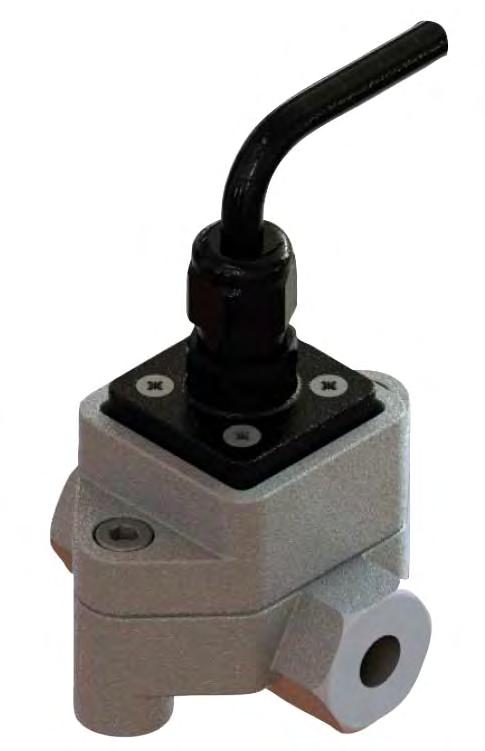
5 6. Mechanical Connection Fluid entering the meter must maintain its liquid state without being solidified. In case of pressure surges, a pressure relief valve should be mounted to protect the device. The device should always be mounted with correct orientation as shown below: Orientation If the above mentioned orientations are not complied with, the device s performance will be degraded leading to reduced life and the damages caused will be the responsibility of the customer. It is highly recommended to INSTALL a filter immediately before (prior to) the meter. Filters are available and sold separately. Recommended Filter: DOE-x05 DOE-x15: < 75 μm particle size (200 mesh) DOE-x20 DOE-x35: < 150 μm particle size (100 mesh) DOE-x40 DOE-x60: < 350 μm particle size (45 mesh) Flow conditioning: Flow conditions are not required since the DOE flowmeter does not require any straight pipe runs before or after the flowmeter. Location: The recommended installation would be before of any flow control and/or shut off valves, this installation prevents complete emptying of the meter. This minimizes the risk of leakage and/or air entrapment which could result in damage to the flowmeter or inaccurate initial readings. A by-pass installation is recommended for process or safety critical meters. Isolation valves enable the meter to be isolated from the system and serviced as needed. System purging is also possible with a by-pass arrangement. Accommodate all meter ratings and locate the meter on the discharge side of the process pump. DOE K01/0817 page 5
6 For outdoor applications, be sure all electrical entries are sealed properly via the proper glands, mounting, sealing or containment. For humid environments, mount the instrument appropriately as to avoid condensation build up. Generally these installations have the conduit connection pointing downward as to drain any condensate away from the electronics. Liquid State: Liquid within the flowmeter must not freeze. If heat tracing is necessary, please be sure to adhere to the temperature limits of the flow meter. Ensure the liquid does not flash, do not exceed the max DP of the flowmeter. Hydraulic shock: Surge dampeners or pressure relief valves must be installed if hydraulic shock or pressure spikes are present. Highly pulsating flow can also damage the DOE flowmeter. Diaphragm pumps and specific application profiles can cause high frequency pulsating flow. Proper pulsating dampers are highly recommended. 7. Electrical Connection 7.1 General Two types of output are available on DOE Oval Gear flow-meter; the standard output is a single NPN Hall Effect sensor, providing a square wave frequency output signal which is linearly proportional to volumetric flow. The optional Fuel Consumption model provides a similar NPN Hall Effect sensor output combined with a Platinum temperature sensor output. The Fuel Consumption model has a specific magnetic sensor design which is tailored to produce accurate measurements on fuel injected combustion engines, which are typically prone to flow pulsations. In addition to the volume measurement, the Fuel Consumption option also provides a temperature measurement of the liquid inside the flowmeter; this allows for temperature compensation of liquid volumes between the inlet and outlet of an engine s fuel system. 7.2 Electronic options Reed switch pulse output (... H0) The reed switch output is a two wire normally open SPST voltage free contact. Note: when using the reed switch output the liquid temperature must not change at a rate greater than 10 ºC per minute. Average switching life of reed contact (MTTF): At max. load 100 V / 10 ma 5 x 10⁵ switching cycles At load <5 V / 10 ma 5 x 10⁸ switching cycles Recommended load: 10 V / 10 ma Hall sensor pulse output (... H0/T0) page 6 DOE K01/0817
7 In these electronics options, a Hall Effect sensor used. The electrical connection is provided in 3-wire version. The output is switched to +Vs via pull up resistor. The external supply voltage is VDC. The high signal is approximately equal to the supply voltage +Vs and the low signal is approximately 0 V. The electrical load will be connected to the supply voltage. Maximum output current (current sink): 10 ma (not short circuit protected). In addition to Hall sensor, the option H0 is equipped with a Reed switch. 7.3 Hall sensor output The NPN Hall Effect is a high resolution solid state 3 wire device which provides an un-sourced, open collector, NPN transistor output. The term unsourced means that no voltage is applied to the output from within the flow-meter. The output of the Hall Effect must be pulled to a high state by an external voltage between 5-24VDC, this is achieved by fitting a pull-up resistor between the signal output (white wire) and the voltage supply (red wire). The pull up resistor ties the open collector output to the available DC voltage level, providing a square wave pulse output, which alternates between ground potential and the DC voltage available at the signal wire. The NPN Hall Effect output is a reliable output type, producing a consistent output irrespective of supply voltage variations below the maximum voltage limit, temperature variations, or mechanical shock. The service life of the Hall Effect output is theoretically infinite, so long as it is protected from high energy voltage spikes. Hall Effect outputs are protected against reverse polarity, and against low energy voltage spikes; however they are not protected against constant overvoltage above the maximum limit of 24V (±5%). Many secondary flow instruments are fitted with an integral pull-up resistor, but if connecting the Hall Effect output to an electronic device that does not contain an integral pull-up resistor, one MUST be fitted by the installer. The pull-up resistor is connected between the signal wire (white) and the +VDC wire (red); recommended pull-up resistor value is 10 kohm, 2.4 kohm is the minimum value. It is NOT recommended to combine any inductive loads on the same voltage supply as your flow-meter, as these components are commonly sources of high frequency interference that may affect the quality of the Hall Effect output signal. Another concern to do with inductive loads on a common voltage source is the potential for voltage spikes well in excess of the 24VDC limit of the Hall Effect sensors. Caution! Make sure that the voltage values of your system correspond with the voltage values of the measuring unit. Make sure that the supply wires are de-energized. Plug in the system according to the connecting diagrams. Attention! Incorrect wiring will lead to damage of the unit s electronics. DOE K01/0817 page 7

 7.5.1 Internal connections 7.")
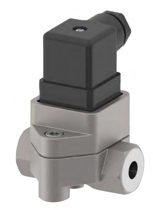
8 7.4 Cable version Option K Connection DOE-...BP wire color red black white yellow green blue Function +Vs 0V/GND Signal PT100-1 PT100-2 PT Connector version Option D (Connector EN ) Internal connections External connection with reed switch output page 8 DOE K01/0817


9 7.5.3 External wiring with Hall sensor output The individually specified maximum electrical values of the reed switch must never be exceeded, even for a moment. Higher switching values may reduce the service life or even destroy the contact. For capacitive and inductive loads (e.g. via long lines), we recommend the following protective circuits: Lamp load with series or parallel resistance to the reed switch. Protection with a RC suppressor For a.c. current and inductive load. Protection with a diode for d.c. current and inductive load. Protection with an inductance or Resistance for capacitive load. DOE K01/0817 page 9


10 8. Commissioning The piping MUST be flushed of debris before installation. Debris such as slag from welding, grinding dust, rust, pipe tape or sealing compound are common within new piping installations and will damage the flowmeter if not flushed or filtered from the process piping before installation and operation. A by-pass system is common for frequent system flushing or frequent meter removal. If a by-pass system is not practical or possible, removal of the gears before flushing is necessary. For proper operation the flowmeter must be purged of air. During long periods of inactivity or after a flushing, air may be in the piping. Elimination of the air may be achieved by operating the meter at a low flow rate until all the air is eliminated. Damage may occur to the flowmeter if it is run above the maximum rated flow rate or if the maximum differential pressure of 15 psi (1 bar, 100 kpa) is exceeded. page 10 DOE K01/0817
11 9. Maintenance Adhering to the installation instructions is the most important requirement to ensure that your Oval Gear meter provides the maximum level of operational performance. Oval Gear meters are a mechanical device, and so will be subject to some wear and tear over their operational life, except under ideal circumstances. The amount of normal wear that the meter will experience will be very dependent on the operational conditions such as; flow rate, temperature, cleanliness of the liquid, lubricity of the liquid, and the amount of continuous duty required of the meter. In order to maximise the operational availability of your meter, and reduce system downtime, a periodic maintenance and inspection regime should be used. Frequency of maintenance depends on the operational conditions of the meter and the criticality of the system; it is the user s responsibility to determine inspection frequency however the manufacturer can provide guidance. For any installations that require in-situ cleaning (CIP); it is important that the cleaning or flushing procedures do not produce operating conditions that are outside of the acceptable flow rate, pressure, or temperature ratings of the meter. Chemical compatibility of cleaning solutions should be checked against the materials of construction of the meter. Before undertaking meter maintenance ensure the following: Associated alarm(s) or control output(s) are isolated so not to affect the process Voltage supply is isolated from the meter Liquid supply to the meter is closed off The meter is depressurised and liquid drained from the meter / pipeline DOE K01/0817 page 11
12 9.1 Disassembly of DOE (Refer to the exploded view diagram) Removal of electronics To remove the electronic assembly: Cable option D: Open the screw (11) of the plug (10). The plug can be removed by pulling it off the connector terminals. The removal of 4 screws (9) from the connector (8) will make the access to the PCB-Board (6) possible. The screw (7) of the PCB (6) should be unscrewed and the complete electronic assembly can be taken out. Cable option K: The removal of 4 screws (13) from the connector (12) will make the access to the PCB-Board (6) possible. The screw (7) of the PCB (6) should be unscrewed and the complete electronic assembly should be taken out carefully without damaging the soldered connections Removal of oval gears To remove the oval gears: Remove the 2 cylinder screws (5) carefully. This will make the removal of the cover (4) possible. The O-ring (3) can then be taken off the flow housing (1) and the oval gears (2) can be easily taken out of the housing. 9.2 Re-Assembly of DOE (Refer to the exploded view diagram) When re-assembling, please insert the rotor (2) with the embedded magnet (for DOE-x05/10) nearest to the dimple located on the meter body (1) face outside the O-ring groove. Install the rotors exactly perpendicular from each other (90 in orientation). They will only work if installed precisely. Manually test full rotation after installation as the rotors will not completely rotate freely unless installed precisely 90 from each other. Proper placement of the O-ring (3) within the groove is necessary for leak free operation. Place the meter cover (4) such that the dimple located on the bottom side of the cover lies on the same side as the dimple on the meter body (1). Tighten the meter bodies (1&4) with the help of 2 cylinder screws (5). Cable option D: The electronic assembly in this case consists of (6), (7), (8), (9) along with the gasket. This assembly can be mounted by first putting the electronic PCB (6) in the cover (4) and screwing it fix with the help of screw (7). Then the gasket will be placed and the connector (8) will be fixed with the help of 4 screws (9). In the end the plug (10) is fixed with screw (11). Cable option K: The electronic assembly in this case consists of (6), (7), (12), (13), (14), (15) along with the gasket. This assembly can be mounted by first putting the electronic PCB (6) in the cover (4) and screwing it fix with the help of screw (7). Then the gasket will be placed and the connector (12) will be fixed with the help of 4 screws (13). page 12 DOE K01/0817
13 Technical Information Material DOE-1 Body: aluminium Oval wheels: PEEK, encapsulated magnets Axes: stainless steel DOE-2 Body: stainless steel Oval wheels: stainless steel , Magnete gekapselt Bearing: carbon graphite Axes: stainless steel DOE-3 Body: stainless steel Oval wheels: stainless steel (gesintert), vernickelte Magnete Bearing: carbon graphite Axes: stainless steel DOE-8 Body: stainless steel Oval wheels: PEEK for x05, x10, x15, PPS für x20 Bearing: carbon graphite O-rings: Axes: Accuracy (under reference conditions*): stainless steel , encapsulated magnets medium temperature FKM: C DOE ±1% of reading (DOE-x05...DOE-x15, DOE-820, DOE-810) ±0,5% of reading (DOE-220, DOE-320) Repeatability: typ. ±0,03% Protection class: IP65 Medium temperature: -20 C C (stainless steel) -20 C C (PEEK) Max. pressure: 64 bar Ambient temperature: -20 C C Electrical connection: valve plug EN form A or 2 m cable UL/cUL 6xAWG20 *Reference conditions: x05...x20 (Mineralöl 10 cst, 20 C, 5 bar) Recommended filter (e.g. model MFR-DO...) DOE-x05...DOE-x15<75 µm micron (200 mesh) DOE-x20<150 µm micron (100 mesh) DOE K01/0817 page 13
14 MFR-DO (version stainless steel) Design: two-part screwed body Connections: female G¼...G½ DIN ISO 228 T1 Pressure rating: PN40 Temperature range: -30 C C Mesh size: 200 mesh/75 µm forr G¼, G⅜ 100 mesh/150 µm for G½ Mounting position: cover toward bottom, note specified direction of flow Materials Body(1): stainless steel , EN Cover (2): stainless steel , EN Mesh (4): stainless steel 316 Cap (9): stainless steel , EN Seal (11): PTFE O-ring (31): FPM page 14 DOE K01/0817
15 10. Order Codes Model DOE- Material/ housing/ rotor 1 = aluminium/ PEEK 2 = st. steel/ st. steel 3 2) = st. steel/ st. steel 8 3) = st. steel/ PEEK Example: DOE-1 05H R1 1 R0 D 0 1) Measuring range Connection Gaskets Elektronics 05H = 0,5-36 l/h 05G = 0,14-9,5 GPH 10H = l/h 10G = 0,5-26,5 GPH 15H = l/h 15G = GPH 20H 2) = 1-40 l/min 20G 2 ) = GPH R1 = G⅛ N1 = ⅛ NPT R2 = G¼ N2 = ¼ NPT R3 = G⅜ N3 = ⅜ NPT R4 = G ½ N4 = ½ NPT Only in combination with cable connection K 2) In preparation 3) Stainless steel/pps for DOE-820 4) Not for measuring ranges 05 and 10 5) Only for option BP 1 = FKM 4 = NBR T0 = pulse output (Hall sensor, NPN, Open Collector), calibrated B0 4) = pulse output (Hall sensor bipolar, NPN, Open Collector) for pulsating flow calibrated BP 1)4) = pulse output (Hall sensor bipolar, NPN, Open Collector) for pulsating flow, Pt100 (3-wire), calibrated H0 = pulse output (Hall sensor, NPN,Open Collector + Reed switch), calibrated Cable exit/entry D = switch acc. EN form A K 5) = 2 m cable Options 0 = without Y = special option (specify in clear text) 10.1 Accessories MFR-DO (version stainless steel) Example: MFR-DOR15 Order no. Size L H D [mm] [mm] [mm] MFR-DOR08 DN08 G¼ 65,0 51,0 10,0 MFR-DOR10 DN10 G⅜ 65,0 51,0 12,0 MFR-DOR15 DN15 G½ 65,0 51,0 15,0 DOE K01/0817 page 15
16 11. Dimensions [mm] DOE-x05...DOE-x10 DOE-x15 page 16 DOE K01/0817
17 DOE-x20 DOE K01/0817 page 17
18 12. EU Declaration of Conformance We, KOBOLD Messring GmbH, Hofheim-Ts, Germany, declare under our sole responsibility that the product: Oval Wheel Flowmeter Model: DOE- to which this declaration relates is in conformity with the directives noted below: 2011/65/EU RoHS (category 9) EN 50581:2013 Technical documentation for the assessment of electrical and electronic products with respect to the restriction of hazardous substances All devices with electronic are in conformance with: 2012/19/EU WEEE Hofheim, 07. September 2017 H. Peters M. Wenzel General Manager Proxy Holder page 18 DOE K01/0817
Operating Instructions for Oval Wheel Flowmeter. Model: DOC
 Operating Instructions for Oval Wheel Flowmeter Model: DOC We don t accept warranty and liability claims neither upon this publication nor in case of improper treatment of the described products. The document
Flow. Oval Wheel Flowmeter Model DOE
 Oval Wheel FIowmeter for low and high viscous liquids measuring monitoring analysing DOE Measuring range: 0.5 36 l/h und 1 40 l/min Viscosity range: 1 1000 cp Accuracy: ±1% of reading Material: stainless
Operating Instructions for Paddle Bellows Flow Monitor. Model: FPS-P...
 Operating Instructions for Paddle Bellows Flow Monitor Model: FPS-P... 1. Contents 1. Contents... 2 2. Note... 3 3. Instrument Inspection... 3 4. Regulation Use... 4 5. Operating Principle... 5 6. Mechanical
Operating Instruction for Flowmonitor. Model: DF-WM
 Operating Instruction for Flowmonitor Model: DF-WM 1. Contents 1. Contents... 2 2. Note... 3 3. Instrument Inspection... 3 4. Regulation Use... 4 5. Operating Principle... 5 6. Mechanical Connection...
Operating Instructions for Flow Indicator. Model: DAA
 Operating Instructions for Flow Indicator Model: DAA 1. Contents 1. Contents... 2 2. Note... 3 3. Instrument Inspection... 3 4. Regulation Use... 3 5. Operating Principle... 4 6. Mechanical Connection...
Operating Instructions for Plastic Flow Meter. Model: KSK
 Operating Instructions for Plastic Flow Meter Model: KSK 1. Contents 1. Contents... 2 2. Note... 3 3. Instrument Inspection... 3 4. Regulation Use... 3 5. Operating Principle... 4 6. Mechanical Connection...
Operating Instructions for Polysulfone Paddle Monitor. Model: PPS-..
 Operating Instructions for Polysulfone Paddle Monitor Model: -.. 1. Contents 1. Contents... 2 2. Note... 3 3. Regulation Use... 3 4. Operating Principle... 3 5. Instrument Inspection... 4 6. Mechanical
Operating Instructions for Float Flow Meter / Monitor. Model: SWK
 Operating Instructions for Float Flow Meter / Monitor Model: SWK 1. Contents 1. Contents... 2 2. Note... 3 3. Instrument Inspection... 3 4. Regulation Use... 4 5. Operating Principle... 4 6. Use in Hazardous
Operating Instructions for Float Flow Meter / Monitor. Model: SWK
 Operating Instructions for Float Flow Meter / Monitor Model: SWK 1. Contents 1. Contents...2 2. Note...3 3. Instrument Inspection...3 4. Regulation Use...4 5. Operating Principle...4 6. Mechanical Connection...5
Operating Instructions for Torsion Paddle Flow Meter / Monitor. Model: DPT-...
 Operating Instructions for Torsion Paddle Flow Meter / Monitor Model: DPT-... 1. Contents 1. Contents... 2 2. Note... 3 3. Instrument Inspection... 3 4. Regulation Use... 4 5. Operating Principle... 4
Operating Instructions for Oval Wheel Flowmeter High pressure. Model: DON-H...R0/H0/Z1/Z2/Z3
 Operating Instructions for Oval Wheel Flowmeter High pressure Model: DON-H...R0/H0/Z1/Z2/Z3 1. Contents 1. Contents... 2 2. Note... 3 3. Instrument Inspection... 3 4. Regulation Use... 4 5. Operating Principle...
Operating Instruction for Electronic Pressure Switch. Model: PDD
 Operating Instruction for Electronic Pressure Switch Model: PDD 1. Contents 1. Contents... 2 2. Note... 3 3. Instrument Inspection... 3 4. Regulation Use... 3 5. Operating Principle... 4 6. Mechanical
Operating Instructions for Magnetic Filter. Model: MFR-00
 Operating Instructions for Magnetic Filter Model: MFR-00 1. Contents 1. Contents... 2 2. Note... 3 3. Instrument Inspection... 3 4. Regulation Use... 3 5. Operating Principle... 4 6. Mechanical Connection...
Operating Instructions for Pressure Transmitter with Digital Display. Model: PDA
 Operating Instructions for Pressure Transmitter with Digital Display Model: PDA 1. Contents 1. Contents... 2 2. Note... 3 3. Instrument Inspection... 3 4. Operating Principle... 3 5. Regulation Use...
OVAL GEAR. Medium capacity positive displacement Pulse flowmeters I N S T R U C T I O N M A N U A L
 OVAL GEAR Medium capacity positive displacement Pulse flowmeters I N S T R U C T I O N M A N U A L Models: 1 (D-150), 1½ (D-250), 2 (D-450) & 2" (D-580) (Extended flow range) Index / contents 1 1.0 General
I N S T R U C T I O N M A N U A L
 I N S T R U C T I O N M A N U A L Oval Gear Positive Displacement Mechanical Flowmeters Models: 3 (080), 3 (080E), 4 (100), 4 (100E) NSW TEL: (02) 9939 0711 FAX: (02) 9939 0411 QLD/PNG TEL: (07) 3204 9166
Flow. Oval Wheel Flowmeter Model DON
 Oval Wheel FIowmeter for low and high viscous liquids measuring monitoring analysing DON OO Measuring range: 0.5 36 l/h und 150 2500 l/min OO Viscosity range: 0 1000 cp (higher on request) OO Accuracy:
Positive displacement flowmeter for continuous flow measurement
 8070 Positive displacement flowmeter for continuous flow measurement High accuracy Medium with high viscosity Mounting and dismounting of the electronics by a quarter-turn Connection to Bürkert devices
I N S T R U C T I O N M A N U A L
 OVAL GEAR Medium Capacity positive displacement Pulse flowmeters I N S T R U C T I O N M A N U A L Model: 1/2 (D-40) Index / contents 1 1.0 General Page 1.1 Overview 2 1.2 Operating principal 2 1.3 Specifications
Operating Instructions for Paddle Flowswitch Model: PPS-...
 Operating Instructions for Paddle Flowswitch Model: PPS-... 1. Note Please read and take note of these operating instructions before unpacking and commissioning. The instruments may only be used, maintained
INSERTION flow sensor for continuous flow measurement
 INSERTION flow sensor for continuous flow measurement Economic integration in pipe systems without any additional piping 3-wire frequency pulse version to directly interface with PLC s (both PNP and NPN)
OVAL GEAR FLOWMETER ELECTRONIC MODEL 019 / ¾
 INST-019P_R4 11/2012 OVAL GEAR FLOWMETER ELECTRONIC MODEL 019 / ¾ INSTRUCTION MANUAL To the Owner PLEASE READ THIS SAFTEY INFORMATION CAREFULLY BEFORE USE. Read and retain this instruction manual to assist
OVAL GEAR. Large Capacity Positive Displacement Mechanical Flowmeters. Models: 3 (D-750), 3 (D-1000), 4 (D-1500) & 4" (D-2500)
, 3 (D-1000), 4 (D-1500) & 4 (D-2500)") OVAL GEAR Large Capacity Positive Displacement Mechanical Flowmeters INSTRUCTION MANUAL Models: 3 (D-750), 3 (D-1000), 4 (D-1500) & 4" (D-2500) Index / contents 1 1.0 General Page 1.1 Overview 2 1.2 Operating
OVAL GEAR Large Capacity Positive Displacement Mechanical Flowmeters INSTRUCTION MANUAL Models: 3 (D-750), 3 (D-1000), 4 (D-1500) & 4" (D-2500) Index / contents 1 1.0 General Page 1.1 Overview 2 1.2 Operating
OVAL GEAR Medium capacity positive displacement Mechanical flowmeters. Model: ½ (15m m)
") OVAL GEAR Medium capacity positive displacement Mechanical flowmeters INSTRUCTION MANUAL Model: ½ (15m m) Index / contents 1 1.0 General Page 1.1 Overview 2 1.2 Operating principal 3 1.3 Specifications
OVAL GEAR Medium capacity positive displacement Mechanical flowmeters INSTRUCTION MANUAL Model: ½ (15m m) Index / contents 1 1.0 General Page 1.1 Overview 2 1.2 Operating principal 3 1.3 Specifications
DOR. Insertion Paddle Wheel Flowmeter/Monitor. for low viscous liquids. Flow range: ,300 l/s to ,000 l/s. Flow velocity range: 0.
 Insertion Paddle Wheel Flowmeter/Monitor for low viscous liquids measuring monitoring analysing DOR Flow range: 0.25 6,300 l/s to 0.4 49,000 l/s Flow velocity range: 0.3-10 m/s Viscosity range: low viscous
Operating Instructions for Viscosity Compensated Flow Meter / Monitor. Model: VKM
 Operating Instructions for Viscosity Compensated Flow Meter / Monitor Model: 1. Contents 1. Contents... 2 2. Note... 3 3. Instrument Inspection... 3 4. Regulation Use... 4 5. Use in Hazardous Areas...
BI-DIRECTIONAL INSERTION FLOW TRANSDUCER
 DUALPULSE BI-DIRECTIONAL INSERTION FLOW TRANSDUCER INSTRUCTION MANUAL DUALPULSE LOCK 1.1 General arrangement Thank you for purchasing a Dualpulse Flowmeter. It is important that you read this manual to
OVAL GEAR FLOWMETER ELECTRONIC MODEL 006/009 (¼ )
") INST-006/009P_R9 06/2015 OVAL GEAR FLOWMETER ELECTRONIC MODEL 006/009 (¼ ) INSTRUCTION MANUAL F Serial Meters To the Owner PLEASE READ THIS SAFTEY INFORMATION CAREFULLY BEFORE USE. Read and retain this
INST-006/009P_R9 06/2015 OVAL GEAR FLOWMETER ELECTRONIC MODEL 006/009 (¼ ) INSTRUCTION MANUAL F Serial Meters To the Owner PLEASE READ THIS SAFTEY INFORMATION CAREFULLY BEFORE USE. Read and retain this
Positive displacement flowmeter
 Positive displacement flowmeter Configurable outputs: one or two transistor output(s) and single or dual 4...20 ma current output(s) Removable backlit display of flow rate and/or 2 two totalized volumes
DOR. Insertion Paddle Wheel Flow Meter/Monitor. for Low Viscous Liquids. Flow range: l/s to l/s. Flow velocity range: 0.
 Insertion Paddle Wheel Flow Meter/Monitor for Low Viscous Liquids measuring monitoring analysing DOR Flow range: 0.25 6300 l/s to 0.4 49000 l/s Flow velocity range: 0.3-10 m/s Viscosity range: low viscous
INSERTION flowmeter with paddle wheel, ELEMENT design
 INSERTION flowmeter with paddle wheel, design Up to PN, size of measurement pipes: DN to DN400 Configurable outputs: one or two transistor output(s) and single or dual 4... ma analog output(s) Removable
DOR Insertion Paddle Wheel Flowmeter
 Benefits and Features Flow Range: 5.5 180 GPM to 25,000 800,000 GPM Flow Velocity Range: 1.0...33.0 ft/s pmax: 1160 PSI tmax: 300 F Connection: 1½" NPT, 2" NPT Male, R 1½, & R 2 Male for Pipe Sizes: 1½"...100"
Operating Instructions for Oval Gear Flow Meter. Model: DON-...Lx/Hx/Rx/Dx/Gx/Kx/Bx/Zx/M4
 Operating Instructions for Oval Gear Flow Meter Model: -...Lx/Hx/Rx/Dx/Gx/Kx/Bx/Zx/M4 1. Contents 1. Contents... 2 2. Note... 3 3. Instrument Inspection... 5 4. Regulation Use... 5 5. Operating Principle...
OVAL GEAR Medium capacity positive displacement flowmeter
 SEE OVER OVAL GEAR Medium capacity positive displacement flowmeter I N S T R U C T I O N M A N U A L Model: (1") 025P PPS Meter Index / contents 1 1.0 General Page 1.1 Overview 2 1.2 PPS Chemical Compatibility
Insertion magnetic inductive flowmeter
 Insertion magnetic inductive flowmeter Sensor without moving parts Flowmeter with On/Off control Application related calibration by Teach-In function Clean in place (CIP) FDA-compliant materials Type 8041
INLINE Flow sensor for hazardous area II 1 G/D - II 2 D - II 3 GD - I M1
 INLINE Flow sensor for hazardous area II G/D - II D - II GD - I M Type SE0 Ex can be combined with... Flow meter with NAMUR or NPN/PNP output signal Mounting, dismounting of electronics by a Quarter-Turn
Paddle-wheel flow controller for On/Off control
 Paddle-wheel flow controller for On/Off control Type 8032 can be combined with... Indication, monitoring, transmitting and On/Off control in one device Programmable outputs (transistor or relay) Automatic-calibration:
ZDM Positive Displacement Flow Meter User Instructions
 ZDM Positive Displacement Flow Meter User Instructions USA 1801 Parkway View Drive Pittsburgh, PA 15205 PH 412-788-2830 Canada 9A Aviation Point Claire, QC H9R 4Z2 PH 514-428-8090 www.koboldusa.com ZDM_manual_05/17
FLOWX3 F3.20 High Pressure Paddlewheel Flow Sensor MAIN FEATURES APPLICATIONS OPERATING PRINCIPLE
 FLOWX3 F3.20 High Pressure Paddlewheel Flow Sensor FlowX3 F3.20 is a paddlewheel flow sensor suitable for system at high pressure and at critical temperature. F3.20 is designed for use with every kind
MX06 - MX100 OVAL GEAR FLOWMETER SERIES
 MXL-INST Rev 7 04/2016 MX06 - MX100 OVAL GEAR FLOWMETER SERIES INSTRUCTION MANUAL To the Owner Please read and retain this instruction manual to assist you in the operation and maintenance of this product.
MX-SERIES OVAL GEAR FLOW METERS
 Data Sheet MX-SERIES OVAL GEAR FLOW METERS Supplied by.com Call us on +44 (0)118 916 9420 Email info@247able.com MX-Series Oval Gear Flow Meters Features and Advantages P From ¼ DN8 at 0.5LPH to 4 DN100
FLS F6.60 MAGMETER FLOW SENSOR INSERTION FLOW SENSORS APPLICATIONS MAIN FEATURES
 FLS F6.60 MAGMETER FLOW SENSOR The new F6.60 and F6.63 are flow meters without moving mechanical parts which can be applied for the measurement of dirty liquids so long as they are conductive and homogeneous.
I N S T R U C T I O N M A N U A L
 I N S T R U C T I O N M A N U A L Oval Gear Positive Displacement Electronic Flowmeters Models: 1 (025), 1 ½ (040), 2 (050), 2 (050E) NSW TEL: (02) 9939 0711 FAX: (02) 9939 0411 QLD/PNG TEL: (07) 3204
OM004, OM006 & OM008 Oval Gear Meter
 OM SERIES OM004, OM006 & OM008 Oval Gear Meter OM004 (1/8"), OM006 (1/4") and OM008 (3/8") Oval Gear Meters ACCURACY: ±1.0% OF READING Select Your Body Material: Aluminum or Stainless Steel The OM Small
Positive Displacement Flowmeters GM020 series instruction manual
 ACCURATE FLOWMETERS & INSTRUMENTATION PVT. LTD. Positive Displacement Flowmeters GM020 series instruction manual GM020 Pulse Meter From serial No. CXXXX Accurate Flowmeters & Instrumentation Pvt. Ltd.
OVAL GEAR Medium capacity positive displacement flowmeters
 Each meter has been calibrated on mineral oil and will contain a small amount of oil residue. The oil used is Castrol Diesel Calibration Fluid 4113 (product code 055830). SEE OVER OVAL GEAR Medium capacity
Insertion turbine INSTRUCTION SHEET. TECHNICAL PRODUCT
 TECHNICAL PRODUCT INSTRUCTION SHEET Insertion turbine OVERVIEW These insertion flow transducers provide a cost effective and simple means of measuring the flow of a wide range of low viscosity liquids.
Operating Instructions for Paddle Flow Monitor. Model: PSR-..., PSE-...
 Operating Instructions for Paddle Flow Monitor Model: PSR-..., PSE-... 1. Contents 1. Contents... 2 2. Note... 3 3. Instrument Inspection... 4 4. Regulation Use... 4 5. Operating Principle... 5 6. Use
Positive displacement batch controller
 8075 Batch controller Positive displacement batch controller Type 8075 can be combined with... Compact version for DN15 to DN100 Dosing On site calibration by Teach-In Check of input/output signals Total
OVAL GEAR FLOWMETER ELECTRONIC MODEL 025 / 1. Type CR for Corrosive Applications
 INST-CR025P_R1 012/2011 OVAL GEAR FLOWMETER ELECTRONIC MODEL 025 / 1 Type CR for Corrosive Applications INSTRUCTION MANUAL To the Owner PLEASE READ THIS SAFTEY INFORMATION CAREFULLY BEFORE USE. Read and
Paddle-wheel flow controller with optical principle for On/Off control
 Paddle-wheel flow controller with optical principle for On/Off control Type 8039 can be combined with... Indication, monitoring, transmitting and On/Off control in one device. Programmable s (transistor
BI-DIRECTIONAL INSERTION METER
 BI-DIRECTIONAL INSERTION METER INSTRUCTION MANUAL LOCK 1 Contents CONTENTS PAGE 1.0 INTRODUCTION 1.1 General arrangement 2 1.2 Overview 3 1.3 Operating principal 3 1.4 Specifications 3 2.0 INSTALLATION
Inductive conductivity meter
 Inductive conductivity meter Type 8228 can be combined with... Configurable outputs: up to 2 transistor and up to 2 analog 4... 20 ma outputs Removable backlighted display Simulation of process values
I N S T R U C T I O N M A N U A L 3 (080), 3 (080E), 4 (100), & 4 (100E)
, 3 (080E), 4 (100), & 4 (100E)") SEE OVER OVAL GEAR Large capacity positive displacement Mechanical Flowmeters I N S T R U C T I O N M A N U A L Models: 3 (080), 3 (080E), 4 (100), & 4 (100E) Index / contents 1 1.0 General Page 1.1 Overview
SEE OVER OVAL GEAR Large capacity positive displacement Mechanical Flowmeters I N S T R U C T I O N M A N U A L Models: 3 (080), 3 (080E), 4 (100), & 4 (100E) Index / contents 1 1.0 General Page 1.1 Overview
OVAL GEAR FLOWMETER ELECTRONIC MODEL 025 / 1
 025 Puls 07.11 OVAL GEAR FLOWMETER ELECTRONIC MODEL 025 / 1 INSTRUCTION MANUAL To the Owner PLEASE READ THIS SAFTEY INFORMATION CAREFULLY BEFORE USE. Read and retain this instruction manual to assist you
Type Operating Instructions. Bedienungsanleitung Manuel utilisateur
 Water flow rate transmitter Wasser-Durchfluss-Transmitter Transmetteur de débit d eau Operating Instructions Bedienungsanleitung Manuel utilisateur We reserve the right to make technical changes without
OM SERIES OVAL GEAR METERS. OM SERIES Oval Gear Meters
 Oval Gear Meters OVAL GEAR METERS OM Series Oval Gear Meters are designed for low flow and high accuracy. OM Series Meters are great for viscous fluids. Units are available with from either a Reed Switch
I N S T R U C T I O N M A N U A L
 ADDIT IV E INJ E C T ION MANIF OLD AIM B lock I N S T R U C T I O N M A N U A L Models: AIM004, AIM006, AIM008 Note: Please read these operating instructions before unpacking and putting the unit into
Positive Displacement Flowmeters GM020 series instruction manual
 MS244G 0603 0003 Positive Displacement Flowmeters GM020 series instruction manual GM020 Pulse Meter From serial No. CXXXX To the owner Thank you for purchasing a GPI GM Series Flow Meter. Please take a
MX06 - MX100 OVAL GEAR FLOWMETER SERIES APPROVED FOR USE IN HAZARDOUS AREAS
 MXEX-INST Rev 9.0 04/2016 MX06 - MX100 OVAL GEAR FLOWMETER SERIES APPROVED FOR USE IN HAZARDOUS AREAS INSTRUCTION MANUAL To the Owner Page 1 of 33 index Installation Pre-installation checks. Page 3 Operating
OVAL GEAR FLOWMETER MECHANICAL MODEL 012 (½ )
") 012 Mech 07.11 OVAL GEAR FLOWMETER MECHANICAL MODEL 012 (½ ) INSTRUCTION MANUAL To the Owner PLEASE READ THIS SAFTEY INFORMATION CAREFULLY BEFORE USE. Read and retain this instruction manual to assist
012 Mech 07.11 OVAL GEAR FLOWMETER MECHANICAL MODEL 012 (½ ) INSTRUCTION MANUAL To the Owner PLEASE READ THIS SAFTEY INFORMATION CAREFULLY BEFORE USE. Read and retain this instruction manual to assist
Inductive conductivity meter
 Inductive conductivity meter CIP version Type 8228 can be combined with... Standard version Perfect for concentrated liquids and wide conductivity range Pre-parameterized versions available for direct
DRT. Ring Piston Flow Meter. for low/high Viscous Liquids
 Ring Piston Flow Meter for low/high Viscous Liquids measuring monitoring analysing DRT Measuring range: 0.2... 10 L/min to 12... 330 L/min Viscosity range: low viscous to high viscous liquids Accuracy:
FPD1001B thru FPD1003B, FPD1102B and FPD1103B, FPD1201B thru FPD1203B SERIES LOW FLOW Positive Displacement Flowmeters
 FPD1001B thru FPD1003B, FPD1102B and FPD1103B, FPD1201B thru FPD1203B SERIES LOW FLOW Positive Displacement Flowmeters To the owner: Please take a few minutes to read through the manual before installing
M-100 Adjustable flow switch with right-angle flow
 M-100 Adjustable flow switch with right-angle flow Operating Instructions and Quick Start Guide Table of Contents Introduction 03 Operation 03 Storage and Handling 03 Installation Instruction 03 Specification
OVAL GEAR Medium capacity positive displacement pulse flowmeter. Size : ½ ( 015mm)
") OVAL GEAR Medium capacity positive displacement pulse flowmeter INSTRUCTION MANUAL Size : ½ ( 015mm) Index / contents 1 1.0 General Page 1.1 Overview 2 1.2 Operating principal 3 1.3 Specifications 4 2.0
OVAL GEAR Medium capacity positive displacement pulse flowmeter INSTRUCTION MANUAL Size : ½ ( 015mm) Index / contents 1 1.0 General Page 1.1 Overview 2 1.2 Operating principal 3 1.3 Specifications 4 2.0
Electronic Pressure Switches
 96 Pressure Switches Electronic Pressure Switches Electronic E.6 2 switching outputs Electronic pressure switches, High-Performance series with two switching outputs Outstanding overpressure protection
KOBOLD DF-MA Flow Transmitter. User Instructions
 KOBOLD DF-MA Flow Transmitter User Instructions KOBOLD Instruments Inc. 1801 Parkway View Drive Pittsburgh PA 15205 Phone (412) 788-2830 Fax (412)-788-4890 www.koboldusa.com Manual-DF-MA_12-13 DF-MA Table
PSF50 Paddle flow switch
 Paddle Flow Switch Paddle Flow Switch PSF50 Paddle flow switch Paddle flap flow / no flow switch Economically priced flow/no flow paddle operated flow switch. Simple and reliable design for liquids up
KOBOLD VKA FLOWMETER/SWITCH. User Instructions. Manual-VKA_03-04
 KOBOLD VKA FLOWMETER/SWITCH User Instructions Manual-VKA_03-04 VKA Table of Contents 1.0 General............................................. 1 Specifications..........................................
POSITIVE DISPLACEMENT FLOWMETERS
 MS345BR 0408 0001 POSITIVE DISPLACEMENT FLOWMETERS M4 BRONZE SERIES INSTRUCTION MANUAL M4 Pulse; M4 Standard LCD; M4 Deluxe LCD; From serial No.CXXXX TO THE OWNER Please take a few minutes to read through
OVAL GEAR FLOWMETER ELECTRONIC MODEL 006/009 (¼ )
") 012 Puls 07.11 OVAL GEAR FLOWMETER ELECTRONIC MODEL 006/009 (¼ ) INSTRUCTION MANUAL To the Owner PLEASE READ THIS SAFTEY INFORMATION CAREFULLY BEFORE USE. Read and retain this instruction manual to assist
012 Puls 07.11 OVAL GEAR FLOWMETER ELECTRONIC MODEL 006/009 (¼ ) INSTRUCTION MANUAL To the Owner PLEASE READ THIS SAFTEY INFORMATION CAREFULLY BEFORE USE. Read and retain this instruction manual to assist
OVAL GEAR FLOWMETER MECHANICAL MODEL 012 (½ )
") INST-012M_R4 11/2012 OVAL GEAR FLOWMETER MECHANICAL MODEL 012 (½ ) INSTRUCTION MANUAL To the Owner PLEASE READ THIS SAFTEY INFORMATION CAREFULLY BEFORE USE. Read and retain this instruction manual to assist
INST-012M_R4 11/2012 OVAL GEAR FLOWMETER MECHANICAL MODEL 012 (½ ) INSTRUCTION MANUAL To the Owner PLEASE READ THIS SAFTEY INFORMATION CAREFULLY BEFORE USE. Read and retain this instruction manual to assist
Paddle-wheel flow controller for On/Off control
 Paddle-wheel flow controller for On/Off control Type 803 can be combined with... Indication, monitoring, transmitting and On/Off control in one device Programmable s (transistor or relay) Automatic-calibration:
OVAL GEAR FLOWMETER MECHANICAL MODEL 075 (3 )
") INST-075M_R4 11/2012 OVAL GEAR FLOWMETER MECHANICAL MODEL 075 (3 ) INSTRUCTION MANUAL To the Owner PLEASE READ THIS SAFTEY INFORMATION CAREFULLY BEFORE USE. Read and retain this instruction manual to assist
INST-075M_R4 11/2012 OVAL GEAR FLOWMETER MECHANICAL MODEL 075 (3 ) INSTRUCTION MANUAL To the Owner PLEASE READ THIS SAFTEY INFORMATION CAREFULLY BEFORE USE. Read and retain this instruction manual to assist
IM012E (ELECTRONIC) POSITIVE DISPLACEMENT FLOWMETER INSTRUCTION MANUAL
 POSITIVE DISPLACEMENT FLOWMETER INSTRUCTION MANUAL") IM012E (ELECTRONIC) POSITIVE DISPLACEMENT FLOWMETER INSTRUCTION MANUAL To the Owner PLEASE READ THIS INFORMATION CAREFULLY BEFORE USE. Read and retain this instruction manual to assist you in the operation
IM012E (ELECTRONIC) POSITIVE DISPLACEMENT FLOWMETER INSTRUCTION MANUAL To the Owner PLEASE READ THIS INFORMATION CAREFULLY BEFORE USE. Read and retain this instruction manual to assist you in the operation
Swing Piston Compressors and Vacuum Pumps
 Swing Piston Compressors and Vacuum Pumps NPK 018 AC Pressure NPK 018 DC Pressure NPK 018 AC Vacuum NPK 018 DC Vacuum Operating and Installation Instructions Read and observe these Operating and Installation
DON. Oval Gear Flowmeter
 Oval Gear Flowmeter for Low and High Viscosity Liquids measuring monitoring analyzing DON Measuring Range: 0.13 9.5 GPH to 40 660 Viscosity Range: up to 1000 cp (Higher upon Request) Accuracy: ± 0.2% 1%
1100 Series Piston Type Differential Pressure Gauges
 1100 Series Piston Type Differential Pressure Gauges 1. Safety Before installing, check the Series Number and verify compatibility to the process media and temperature in contact with the wetted parts.
Electronic Pressure Switches
 96 Pressure Switches Electronic Pressure Switches Electronic E.5 switching output Electronic pressure switches, High-Performance series with one switching output Outstanding overpressure protection (up
F111.X Flow Sensor for Hot Tap Installation INSTRUCTION MANUAL. 1. Introduction Safety Instructions Unpacking Description.
 F111.X Flow Sensor for Hot Tap Installation INSTRUCTION MANUAL EN 08-05 Table of Contents 1. Introduction 2 1.1. Safety Instructions 2 1.2. Unpacking 2 2. Description. 2 2.1. Main Features.. 3 2.2. Technical
Declaration of Conformity as per Directive 97/23/EC
 Declaration of Conformity as per Directive 97/23/EC The manufacturer declares that:, 47906 Kempen, Germany PTFE-lined Rotary plug valves Series 23e, with packing with lever for 90 operation with worm gear
Type 2712 (8630) Continuous TopControl System. General data Compatibility Materials of wetted parts Body Rotor Shaft Seal
 Continuous TopControl System. General data Compatibility Materials of wetted parts Body Rotor Shaft Seal") Positive displacement flow fitting for continuous and batch control High accuracy ± 0.5% 1/2 TO 4 (DN 15 to 100) INLINE Quarter Turn technology For highly viscous fluids Electronics for indication, monitoring,
Positive displacement flow fitting for continuous and batch control High accuracy ± 0.5% 1/2 TO 4 (DN 15 to 100) INLINE Quarter Turn technology For highly viscous fluids Electronics for indication, monitoring,
MODEL MX75 3 OVAL GEAR FLOWMETER
 Installation & Maintenance Instructions MODEL MX75 3 OVAL GEAR FLOWMETER Supplied by.com Call us on +44 (0)118 916 9420 Email info@247able.com MXL-INST75 Rev 1 06/2013 MODEL MX75 3 OVAL GEAR FLOWMETER
MODEL MX12 1/2 OVAL GEAR FLOWMETER
 MXL-INST12 Rev 4 12/2013 MODEL MX12 1/2 OVAL GEAR FLOWMETER INSTRUCTION MANUAL To the Owner Please read and retain this instruction manual to assist you in the operation and maintenance of this product.
ProFlow TO BE REALLY SURE. Vane Meters. Experience in flow measurement. Introduction
 ProFlow N142 P R O D U C T B U L L E T I N Vane Meters Special versions This brochure comprises only VAF Instruments standard delivery program. Special flowmeter variants can be offered as tailor-made
Positive Displacement Flowmeters GM007 series instruction manual
 MS499G 0603 0003 Positive Displacement Flowmeters GM007 series instruction manual GM007 Pulse Meter From serial No. CXXXX To the owner Thank you for purchasing a GPI GM GPI by telephone or fax.] Series
MULTIPULSE PISTON POSITIVE DISPLACEMENT FLOWMETER
 SEE OVER MULTIPULSE PISTON POSITIVE DISPLACEMENT FLOWMETER Models : MP015 MP020 MP025 MP040 MP050 INSTRUCTION MANUAL Index / contents 1 1.0 General Page 1.1 Overview 2 1.2 Operating principal 3 1.3 Specifications
Digital Pressure Regulator Sentronic PLUS Series 614
 Digital Pressure Regulator Sentronic PLUS Series 14 Installation manual IM149-/R01 CONTENTS 1. Description... 1.1 Catalogue number... 1. Operating elements...4 1. Operating modes...4. Electrical connection...5.
ITVX Series. Stepless control of air pressure proportional to an electrical signal. Supply pressure: 5.0 MPa
 5.0 MPa Maximum Supply Pressure High Pressure Electro-Pneumatic Regulator X Series This product is only for blowing gas. This product does not have sufficient pressure control for other applications (driving,
Differential Pressure Sensors
 1 920 1920P01 Differential Pressure Sensors for neutral and mildly corrosive liquids and gases QBE63-DP Differential pressure sensor, suitable for gases and liquids, for the measurement of positive and
Mounting and Operating Instructions EB 5868/5869 EN
 Electric Control Valves Types 3213/5857, 3213/5824, Types 3214/5824, 3214/3374, 3214/3274 with safety function: Types 3213/5825, 3214/5825, 3214/3374, 3214/3274 Pneumatic Control Valves Types 3213/2780-1,
FPD1001 thru FPD1003, FPD1102 and FPD1103, FPD1201 thru FPD1203 (includes -R Option) Positive Displacement Flowmeters
 Positive Displacement Flowmeters") FPD1001 thru FPD1003, FPD1102 and FPD1103, FPD1201 thru FPD1203 (includes -R Option) SERIES LOW Flow Positive Displacement Flowmeters To the owner: Please take a few minutes to read through the manual
FPD1001 thru FPD1003, FPD1102 and FPD1103, FPD1201 thru FPD1203 (includes -R Option) SERIES LOW Flow Positive Displacement Flowmeters To the owner: Please take a few minutes to read through the manual
Product. Information. A.u.K. Müller. Flow meter turbine, with shut-off device. Series Characteristics. Applications.
 Series 7.007 Solenoid valves Control valves Special valves and systems A. u. K. Müller GmbH & Co. KG Dresdener Str. 6 D-40595 Düsseldorf/Germany Tel.: +49(0)-79-0 Fax: +49(0)-79-8 e-mail: info@akmueller.de
POSITIVE DISPLACEMENT FLOWMETER
 Includes models IM019E-01 IM019E-02 IM019E (ELECTRONIC) POSITIVE DISPLACEMENT FLOWMETER INSTRUCTION MANUAL To the Owner PLEASE READ THIS INFORMATION CAREFULLY BEFORE USE. Read and retain this instruction
OVAL GEAR. Medium Capacity Positive Displacement Mechanical Flowmeters. Models: 1 (D-150), 1½ (D-250), 2 (D-450) & 2" (D-580)
, 1½ (D-250), 2 (D-450) & 2 (D-580)") OVAL GEAR Medium Capacity Positive Displacement Mechanical Flowmeters INSTRUCTION MANUAL Models: 1 (D-150), 1½ (D-250), 2 (D-450) & 2" (D-580) Index / contents 1 1.0 General Page 1.1 Overview 2 1.2 Operating
OVAL GEAR Medium Capacity Positive Displacement Mechanical Flowmeters INSTRUCTION MANUAL Models: 1 (D-150), 1½ (D-250), 2 (D-450) & 2" (D-580) Index / contents 1 1.0 General Page 1.1 Overview 2 1.2 Operating
SOLENOID VALVES FOR REFRIGERATING SYSTEMS
 SOLENOID VALVES 17 SOLENOID VALVES FOR REFRIGERATING SYSTEMS APPLICATIONS The solenoid valves, shown in this chapter, are classified Pressure accessories in the sense of the Pressure Equipment Directive
macnaught flow measurement
 macnaught flow measurement fuel and oil meters macnaught.com.au flow meters fuel and oil macnaught flow measurement The F range of oval gear fuel and oil meters from Macnaught are positive displacement
RUN ACCUM. TOTAL STOP BAT LOW HIGH
 TURBOPULSE TURBINE FLOWMETER INSTRUCTION MANUAL gal RUN ACCUM. TOTAL STOP BAT LOW HIGH RESET > PROGRAM ENTER ACCUM TOTAL ^ RATE TOTAL TP050 TABLE OF CONTENTS 1. INTRODUCTION Overview 1 1.1 Model number
INSTALLATION, SERVICE AND MAINTENANCE INSTRUCTIONS Y-FILTER 83700
 INSTALLATION, SERVICE AND MAINTENANCE INSTRUCTIONS Y-FILTER 83700 11.106.32.0001 INOXPA, S.A. c/telers, 54 Aptdo. 174 E-17820 Banyoles Girona (Spain) Tel. : (34) 972-57 52 00 Fax. : (34) 972-57 55 02 email: