J.C. Renfroe & Sons has been an international leader in the manufacturing and marketing of lifting products for over 70 years.
|
|
|
- Alyson Nelson
- 5 years ago
- Views:
Transcription

1

2 3
3 J.C. Renfroe & Sons has been an international leader in the manufacturing and marketing of lifting products for over 70 years. Corporate Headquarters Jacksonville, Florida Telephone: Toll Free: Fax: USA Plant Location J.C. Renfroe & Sons 1926 Spearing Street Jacksonville, Florida Partnering Plants Spain Germany NOTICE OF EXCLUSION OF WARRANTY RENFROE HAS HEREIN SET FORTH IN CONSPICUOUS LANGUAGE AN EXCLUSION OF ANY WARRANTY EITHER EXPRESSED OR IMPLIED, WHICH IS NOT SPECIFICALLY AND PARTICULARLY CONTAINED HEREIN. PLEASE REFER TO THAT STATEMENT FOR REPRESENTATIONS AND WARRRANTIES OF PRODUCTS MANUFACTURED BY J.C. RENFROE & SONS Copyright 2015 J.C. Renfroe & Sons 11COM Supersedes Catalog 4COM
4 Table of Contents Table of Content Renfroe Information 1 Table of Contents 2 & 3 The Renfroe Story (history & plant photos) 4 Clamp Index 8 Collage Vertical Only Clamps 9 BD 10 FR 11 FRD 12 R 13 RO 14 S 15 SD 16 Collage Vertical J 18 L 19 LJ 20 TL 21 Collage Vertical 90 + Side Pull 22 JP 23 LP 24 Collage Vertical DC 26 JA 27 LA 28 PCK-SL 29 RSC 30 SCP 31 SCSL 32 SCSM 33 TLA 34 Collage Vertical Side Pull 35 JPA 36 LPA 37 SCPA 38 Collage Structural - Shapes 39 AST 41 ASTL 42 2
5 Table of Contents AST-S 43 DG 44 M 45 SEA 46 SX 47 Collage - Horizontal 48 DWS 49 HR 50 HDR 51 HRS 52 M 53 WHSR 54 Collage - Beam 55 A-1 56 AC 57 ACP 58 B-1 59 B-2 60 BC 61 PB 62 Collage Pull 63 PC 64 Collage Non-Marring 65 NM 66 NMA 67 NMBL 68 NMRSC 69 Collage Drum Lifter S M 72 Collage Tool 73 Tagline 75 Pry Tool 76 Product Testing 77 Do s & Don ts 78 Definitions 79 & 80 General Information 81 Manuals and Rebuild Kits 82 Sheave Introduction 84 Sheave Dimensions & Size Charts Model S Synthetic Sheaves 90 Bearings/Sales Policies/Definitions 91 Sheave Inquiry Sheet 92 Sheave Order Form 93 Sheave Installation, Operation & Maintenance 94 & 95 Bridge Crane Block Capacities 97 Din Hook Block 98 Mobile Crane Block Data Block Maintenance & Inspection 103 Block Inquiry Order Form 104 Block Operator Manual Load Weighing Blocks 113 Load Weighing Block Data 114 Load Weighing Block Single Sheave 115 Load Weighing Block 2 Sheave 116 Load Weighing Block Motorized Sheave 117 Load Weighing Block 4 Sheave 118 Snatch Block Features 120 Snatch Block Dimensions 121 Snatch Block Hook Assembly 122 Snatch Block Shackle Assembly 123 Snatch Block Tailboard Assembly 124 Snatch Block Warning 125 & 126 Swivels 128 Swivel Part Numbers 129 Swivel Dimensions 130 & 131 Load Limiter 133 3


6 The Renfroe Story J.C. RENFROE & SONS HAS BEEN A LEADER IN THE MANUFACTURING AND MARKETING OF LIFTING PRODUCTS FOR OVER 70 YEARS. Renfroe products are manufactured in Jacksonville, Florida and Germany. A worldwide network of stocking distributors provides a readily available source of supply and service. We have a distinguished heritage at J.C. Renfroe & Sons. When our country has called, we have responded. The historic Liberty Bell in Philadelphia, Pennsylvania, needed to be relocated with great care. Our lifting products were used. After the space shuttle Challenger tragedy, we were called to design a special clamp to aid in the recovery of the debris. When they needed lifting capabilities for our nuclear submarines, we were there. History has proven when our country needed the very best, Renfroe was called. The Renfroe legacy began in 1940 with Joseph Renfroe and his four sons. The standard of excellence on which the company was founded exists today with J.C. Renfroe II, grandson of the founder, overseeing the final inspections of Renfroe clamps. Renfroe s innovative technology and streamlined manufacturing produces the highest quality lifting products in the industry. Our close-knit employee family continues to work with the same dedication to excellence as our founders. 4

7 --

8 Whether it s big, small or somewhere in between, if your operation depends on using the right size lifting clamp for the job, you need a Renfroe clamp. That s because J.C. Renfroe has an extensive selection of products with many rated lifting capacities. We re so determined that you find the right model for your lifting needs that, if you can t find it from our line of clamps, we ll happily engineer one specially suited to your application. We even offer free safety surveys and training seminars for our customers. That s what comes from being tuned into our customers needs and wants for more than 65 years. It s no wonder that outstanding customer service and on-time deliveries rank right up there with our being able to offer you the best quality lifting clamp in the industry. For more information on how we size up, contact us today for an on-the-spot consultation about your lifting needs. Giving Industry the Lift It Needs! Jacksonville, FL USA Fax Toll-Free


9 7
10 Renfroe Clamp Index CLAMP INDEX Model PLATE AND FABRICATED VERTICAL ONLY BD Non-Locking Type 10 FR Locking Type 11 FRD Locking Type 12 R Locking Type 13 RO Non-Locking Type 14 S Locking Type 15 SD Locking Type 16 VERTICAL + 90 J Locking Type 18 L Locking Type 19 LJ Locking Type 20 TL Locking Type 21 VERTICAL SIDE PULL JP Locking Type 23 LP Locking Type 24 VERTICAL DC Locking Type 26 JA Locking Type 27 LA Locking Type 28 PCK-SL Locking, Screw Type 29 RSC Locking, Screw Type 30 SCP Locking, Screw Type 31 SCSL Locking, Screw Type 32 SCSM Locking, Screw Type 33 TLA Locking Type 34 VERTICAL SIDE PULL JPA Locking Type 36 LPA Locking Type 37 SCPA Locking, Screw Type 38 HORIZONTAL DWS Locking Type 49 HR Non-Locking Type 50 HDR Non-Locking Type 51 HRS Locking Type 52 M Locking Type 53 WHSR Non-Locking Type 54 BEAM A-1 Locking Type 56 AC Locking, Screw Type 57 ACP Locking, Screw Type 58 B-1 Locking Type 59 B-2 Trolley Clamp 60 BC Locking Type 61 PB Locking Type 62 PULL PC Locking, Screw Type 64 NON-MARRING NM Locking, Screw Type 66 NMA Locking Type 67 NMBL Locking Type 68 NMRSC Locking, Screw Type 69 DRUM LIFTERS Vertical Only 300-S Locking Type M Locking Type 73 TOOL Tagline Tool Clamp 75 Pry Tool Tool 76 STRUCTURAL SHAPES AST Non-Locking Type 41 ASTL Non-Locking Type 42 AST-S Locking Type 43 DG Locking Type 44 M Locking Type 45 SEA Locking Type 46 SX Locking Type 47 8

11 PLATE AND FABRICATED VERTICAL ONLY 9

 GRIPPING CAM")
12 BD Clamp Model BD Non-Locking Type The Model BD is a vertical lifting, non-locking clamp used primarily for steel warehousing and bench work where a locking type clamp is not essential. The clamp is a low-cost, low maintenance tool that features lightweight and compact size. It is recommended for use and application where constant tension is applied to the lifting shackle throughout the entire operation. PLATE AND FABRICATED VERTICAL ONLY MODEL BD EXPLODED VIEW CONNECTING LINK SPACER SLEEVE BD-6 SHACKLE PIN BD-2 FLOATING PIN BD-7 SLEEVE LIFTING SHACKLE BD-1 CONNECTING LINK BD-3 (2 REQD) GRIPPING CAM BD-8 CONNECTING LINK BOLT ASSY BD-10 BODY BOLT, NUT & SLEEVE BD-5 CAM PIN BD-9 SWIVEL JAW BD-4 SPECIFICATIONS (in inches) Rated Plate Capacity Thickness MAX. Weight Tons A B C D E F G H J (in pounds) 1/ SPECIFICATIONS ARE SUBJECT TO CHANGE WITHOUT NOTICE. 10

 Rated Plate Capacity Thickness MAX.")
13 FR Clamp Model FR Locking Type The Model FR is a vertical lifting tool for relatively light work. It is small and easy to handle in capacities through three tons. It incorporates a Lock Closed feature which facilitates attaching the clamp to the plate. MODEL FR EXPLODED VIEW BODY BOLT & SPACER SLEEVE SET (2RQD) FR-30 LOCK STOP PIN FR-31 CAM PIN FR-4 SHACKLE PIN FR-3 SWIVEL JAW FR-5 LIFTING SHACKLE FR-1 LOCK ASSEMBLY FR-7 LOCK RING & S HOOK FR-8 LOCK SPRING FR-6 PLATE AND FABRICATED VERTICAL ONLY CAM ASSEMBLY FR-2 SPECIFICATIONS (in inches) Rated Plate Capacity Thickness MAX. Weight Tons A B C D E F G H J (in pounds) 1/ SPECIFICATIONS ARE SUBJECT TO CHANGE WITHOUT NOTICE

 Rated Plate Capacity Thickness MAX.")
14 FRD Clamp Model FRD Locking Type The Model FRD is a vertical lifting clamp that incorporates two Model FR clamps into one and is used for heavy duty work where it is desirable to spread the gripping surfaces with two points of contact. The clamp contains two Lock Closed mechanisms which are activated by a single chain and a manually operated Lock Open mechanism. PLATE AND FABRICATED VERTICAL ONLY MODEL FRD EXPLODED VIEW BODY BOLT & SPACER SLEEVE FRD-30 LOCK STOP PIN FRD-31 SHACKLE PIN FRD-3 CAM PIN FRD-4 SWIVEL JAW FRD-5 LIFTING SHACKLE FRD-1 LOCK OPEN FRD-8 CAM ASSEMBLY FRD-2 LOCK ASSEMBLY FRD-7 LOCK SPRING FRD-6 SPECIFICATIONS (in inches) Rated Plate Capacity Thickness MAX. Weight Tons A B C D E F G H I J (in pounds) SPECIFICATIONS ARE SUBJECT TO CHANGE WITHOUT NOTICE. 12
.")
15 RO Clamp Model R Locking Type The Model R is a vertical lifting clamp primarily used in the handling of heavy steel plate in a wide range of plate thicknesses. Specific models are available for handling hot plate (refer to factory for maximum temperatures and recommended application). The Model R incorporates a Lock Open, Lock Closed feature which facilitates attaching and removing the clamp from the plate. MODEL R EXPLODED VIEW PLATE AND FABRICATED VERTICAL ONLY SPECIFICATIONS (in inches) Rated Plate Capacity Thickness Weight Tons A B C D E F G (in pounds) SPECIFICATIONS ARE SUBJECT TO CHANGE WITHOUT NOTICE. 13

16 R Clamp Model RO Non-Locking Type The Model RO incorporates a Lock Open Only feature allowing the clamp to be Locked Open, lifted onto a hot plate and the lock released without the operator coming in close contact with the hot plate. PLATE AND FABRICATED VERTICAL ONLY MODEL RO EXPLODED VIEW SPECIFICATIONS (in inches) Rated Plate Capacity Thickness Weight Tons A B C D E F G (in pounds) SPECIFICATIONS ARE SUBJECT TO CHANGE WITHOUT NOTICE. 14

17 S Clamp Model S Locking Type The Model S is a vertical lifting clamp and is an effective tool for construction and erection. It incorporates a Lock Open, Lock Closed feature which facilitates attaching and removing the clamp from the plate. MODEL S EXPLODED VIEW LIFTING SHACKLE S-25 SHACKLE PIN S-26 TOP ROLLER S-24 (PAIR) CAM PIN S-29 Swivel Jaw S-28 SPECIFICATIONS (in inches) TOP ROLLER S-24 (PAIR) LOCK ASSEMBLY S-21 LOCK SPRING S-22 CAM ASSEMBLY S-23 Rated Plate Capacity Thickness MAX. Weight Tons A B C D E F G H J (in pounds) 1/ * * SPECIFICATIONS ARE SUBJECT TO CHANGE WITHOUT NOTICE. OTHER CAPACITIES AVAILABLE UPON REQUEST. *For handling heavy plate or hot material, see Model R. PLATE AND FABRICATED VERTICAL ONLY 15

18 SD Clamp Model SD Locking Type The SD is a vertical lifting clamp that incorporates two Model S clamps into one and is used for heavy duty work where it is desirable to spread the gripping surfaces with two points of contact. It incorporates a Lock Open, Lock Closed feature which facilitates attaching and removing the clamp from the plate. PLATE AND FABRICATED VERTICAL ONLY MODEL SD EXPLODED VIEW SHACKLE PIN SD-46 BODY BOLT & SPACER SLEEVE SET SD-30 LIFTING SHACKLE SD-45 LOCK ASSEMBLY SD-41 LOCK SPRING SD-42 BOTTOM ROLLER PIN SD-31 CAM PIN SD-49 SWIVEL JAW SD-48 CAM ASSEMBLY SD-43 SPECIFICATIONS (in inches) Rated Plate Capacity Thickness MAX. Weight Tons A B C D E F G H I J (in pounds) SPECIFICATIONS ARE SUBJECT TO CHANGE WITHOUT NOTICE. OTHER CAPACITIES AVAILABLE UPON REQUEST. 16

19 VERTICAL

20 J Clamp Model J Locking Type The Model J is a vertical lifting clamp capable of turning a single plate or member from horizontal to vertical and back to horizontal through the same 90 degree arc. MODEL J EXPLODED VIEW LIFTING SHACKLE J/JA-1 BODY BOLT & SPACER SLEEVE JPA-16 BODY BOLT & SPACER SLEEVE J/JP-15 BODY BOLT & SPACER SLEEVE J/JP-15 SHACKLE PIN JPA-3 LOCK ASSEMBLY J/JP-12 CAM PIN JPA-6 SWIVEL JAW PIN & SPRING KIT JPA-11 VERTICAL + 90 SWIVEL JAW PIN JPA-9 SWIVEL JAW HOUSING JPA-10 SWIVEL JAW JPA-8 LOCK SPRING JPA-7 CAM ASSEMBLY JPA-5 SPECIFICATIONS (in inches) Rated Plate Capacity Thickness MAX. Weight Tons A B C D E F G H J (in pounds) 1/ Consult factory for possible larger capacities. SPECIFICATIONS ARE SUBJECT TO CHANGE WITHOUT NOTICE 18
 Rated Plate Capacity Thickness MAX.")
21 L Clamp Model L MODEL L EXPLODED VIEW SHACKLE PIN L-3 LIFTING SHACKLEL-1 SPRING L-6 E J VERTICAL + 90 LOCK ASSY L-7 BODY BOLT & SPCR SLEEVES L-10 CAM ASSEMBLY L-2 D C B CAM PIN L-4 SWIVEL JAW L-5 H A F G SPECIFICATIONS (in inches) Rated Plate Capacity Thickness MAX. MAX. Weight Tons A B C D E F G H J (in pounds) 1/2 0-5 / / /8 4 1 /4 2 7 / /8 3/8 4 1 / / / /8 4 3 /8 2 7 / /8 1/2 5 1 / / / /2 2 3 /8 7 1 / /8 2 3 /8 3/ / / /8 8 1 / / /4 3/4 32 Consult factory for possible larger capacities. SPECIFICATIONS ARE SUBJECT TO CHANGE WITHOUT NOTICE 19

22 LJ Clamp Model LJ Locking Type The MODEL LJ is a vertical lifting clamp capable of turning a plate from horizontal to vertical and back through the same ninety-degree arc. It is small and easy to handle in capacities through three tons. The Model LJ incorporates a Lock Closed feature, which facilitates attaching the clamp to the plate. MODEL LJ EXPLODED VIEW LIFTING SHACKLE LJ-1 SHACKLE PIN LJ-3 VERTICAL + 90 BODY SPACER SLEEVE LJ-10 BODY BOLT LJ-9 LOCK STOP PIN CAM ASSEMBLY LJ-2 LOCK ASSEMBLY LJ-7 LOCK RING & S HOOK LJ-8 CAM, CAM JAW PIN LJ-4 CAM JAW LJ-5 LOCK SPRING LJ-6 SPECIFICATIONS (in inches) Rated Plate Capacity Thickness MAX. Weight Tons A B C D E F G H J K (in pounds) 1/ SPECIFICATIONS ARE SUBJECT TO CHANGE WITHOUT NOTICE

23 TL Clamp Model TL Locking Type The Model TL is a vertical lifting clamp capable of turning a single plate or member from horizontal to vertical and back to horizontal through the same 90 degree arc. MODEL TL EXPLODED VIEW LIFTING SHACKLE-TL1 SHACKLE PIN TL-3 BODY BOLT & SLEEVE TL-6 BODY SPACER SLEEVE TL-10 BODY BOLT TL-7 LOCK STOP PIN SPRING TL-8 PIN. CAM & CAM JAW TL-4 CAM JAW TL-5 LOCK HANDLE ASSY TL-9 CAM ASSEMBLY TL-2 SPECIFICATIONS (in inches) Rated Plate Capacity Thickness MAX. MAX. Weight Tons A B C D E F G H J (in pounds) 1/ Consult factory for possible larger capacities. SPECIFICATIONS ARE SUBJECT TO CHANGE WITHOUT NOTICE VERTICAL

24 22 VERTICAL SIDE PULL


25 JP Clamp MODEL JP EXPLODED VIEW BODY BOLT & SPACER SLEEVE JPA-16 SHACKLE YOKE PIN JPA-30 LIFTING SHACKLE PIVOTED JP/JPA-2 BODY BOLT & SPACER SLEEVE J/JP-15 Model JP Locking Type The Model JP is a vertical lifting clamp capable of turning a single plate or member from horizontal to vertical and back to horizontal through the same 90 degree arc. Permits side loading of lifting shackle up to 90 degrees by derating of clamp s rated capacity. Refer to FIGURE 1 for derated capacities. Model JP incorporates a pivoting shackle that permits side loading of the lifting shackle at 100 percent of rated capacity from vertical to 30 degrees, 75 percent of rated capacity between 30 and 45 degrees and 50 percent of rated capacity between 45 and 90 degrees BODY BOLT & SPACER SLEEVE J/JP-15 SHACKLE PIN JPA-3 SWIVEL JAW PIN & SPRING KIT JPA-11 CAM PIN JPA-6 SWIVEL JAW PIN JPA-9 SWIVEL JAW HOUSING JPA-10 SWIVEL JAW JPA-8 LOCK ASSEMBLY J/JP-12 LOCK SPRING JPA-7 CAM ASSEMBLY JPA-5 SPECIFICATIONS (in inches) Rated Plate Capacity Thickness MAX. MAX. Weight Tons A B C D E F G H J (in pounds) 1/ FIGURE 1 VERTICAL SIDE PULL Consult factory for possible larger capacities. SPECIFICATIONS ARE SUBJECT TO CHANGE WITHOUT NOTICE 23

26 LP Clamp Model LP The Model LP is an ergonomic vertical lifting clamp capable of turning a single plate or member from horizontal to vertical to horizontal through a 90 degree arc. Permits side loading of lifting shackle to 90 degrees by de-rating of clamp s capacity. Refer to FIGURE 1 for de-rated capacities. The Lock Open Lock Closed feature facilitates attaching and removing the clamp from the plate. Model LP incorporates a pivoting shackle that permits side loading of the lifting shackle at 100 percent of rated capacity from vertical to 30 degrees, 75 percent of rated capacity between 30 and 45 degrees, and 50 percent of rated capacity between 45 and 90 degrees. VERTICAL SIDE PULL MODEL LP BODY BOLT & SPCR SLEEVES LP - 10 EXPLODED VIEW LIFTING SHACKLE LP - 1 SHACKLE PIN LP - 3 SPRING LP - 6 LOCK ASSY LP - 7 CAM ASSEMBLY LP - 2 CAMPIN LP - 4 H SPECIFICATIONS (in inches) Rated Plate Capacity Thickness MAX. MAX. Weight Tons A B C D E F G H J (in pounds) 1/2 0-5 / / / /8 4 1 /4 2 7 / /8 3/8 4 1 / / / / /8 4 3 /8 2 7 / /8 1/2 5 1 / / / /2 1 7 /8 7 1 / /8 2 3 /8 3/ / / /8 8 1 / / /4 3/4 32 Consult factory for possible larger capacities. SPECIFICATIONS ARE SUBJECT TO CHANGE WITHOUT NOTICE 24

27 VERTICAL


28 DC Clamp Model DC Locking Type Model DC is vertical lifting, locking and 180 turning clamp. The DC s unique design, utilizing two movable gripping cams, allows this clamp to lift any load within its plate size range from 0 up to 6 ton with a 300 Brinell hardness or less. MODEL DC EXPLODED VIEW SHACKLE DC-1 SHACKLE PIN DC-4 CAM ASSY- SPRING SIDE DC-2 VERTICAL CAM ASSY-OPEN SIDE DC-2A CAM PIN DC-3 LOCK ASSY DC-6 LOCK SPRING DC-5 SPECIFICATIONS (in inches) Rated Plate Model Capacity Thickness MAX. Weight Tons A B C D E F G H J (in pounds) DC-A 1 /2 0-5 /8 2 5 / /8 1 1 /8 4 3 /8 2 5 /8 1 7 /8 5 /16 6 DC-B 1 /2 0-3 /4 2 9 / / /4 1 1 /8 5 1 /2 2 3 /4 2 3 /8 5 /16 9 DC-C 1 /2 3 /4-1 1 /2 2 9 / /8 9 1 /2 1 1 /8 6 1 /4 2 3 /4 2 3 /8 5 /16 10 DC /8 3 3 /8 7 5 / /8 2 5 /8 6 3 /8 3 3 /4 2 5 /8 5/16 15 DC 3 0-3/4 4 3 /4 9 1 / /4 3 5 / /8 3 5 /8 3/4 30 DC / / / /2 4 3 /4 4 3 /4 1 1 /2 54 DC / / / / /8 4 3 / /2 51 DC / / / /8 4 3 / /2 51 SPECIFICATIONS ARE SUBJECT TO CHANGE WITHOUT NOTICE. 26

29 JA Clamp MODEL JA EXPLODED VIEW Model JA Locking Type The Model JA is a vertical lifting clamp capable of turning a single plate or member from horizontal to vertical to horizontal through a 180 degree arc. It incorporates a push button auxiliary lock. LIFTING SHACKLE J/JA-1 BODY BOLT & SPACER SLEEVE JPA-16 SHACKLE PIN JPA-3 AUX LOCK HOUSING & SLEEVE JA/JPA-14 LOCK ASSEMBLY JA/JPA-13 CAM PIN JPA-6 SWIVEL JAW PIN & SPRING KIT JPA-11 SWIVEL JAW PIN JPA-9 SWIVEL JAW HOUSING JPA-10 SWIVEL JAW JPA-8 LOCK SPRING JPA-7 CAM ASSEMBLY JPA-5 SPECIFICATIONS (in inches) Rated Plate Capacity Thickness MAX. MAX. Weight Tons A B C D E F G H J (in pounds) 1/ VERTICAL Consult factory for possible larger capacities. SPECIFICATIONS ARE SUBJECT TO CHANGE WITHOUT NOTICE
30 LA Clamp Model LA MODEL LA EXPLODED VIEW VERTICAL LIFTING SHACKLE LA-1 SHACKLE PIN LA-3 AUX LOCK HOUSIING LPA-8 SPRING LA-6 E J LOCK ASSY LA-7 BODY BOLT & SPCR SLEEVES LA-10 CAM ASSEMBLY LA-2 D C B CAM PIN LA-4 SWIVEL JAW LA-5 H A F G SPECIFICATIONS (in inches) Rated Plate Capacity Thickness MAX. MAX. Weight Tons A B C D E F G H J (in pounds) 1/2 0-5 / / /8 4 1 /4 2 7 / /8 3/8 4 1 / / / /8 4 3 /8 2 7 / /8 1/2 5 1 / / / /2 2 3 /8 7 1 / /8 2 3 /8 3/ / / /8 8 1 / / /4 3/4 32 Consult factory for possible larger capacities. SPECIFICATIONS ARE SUBJECT TO CHANGE WITHOUT NOTICE 28

31 PCK Clamp Model PCK-SL Locking, Screw Type The PCK Locking Screw Clamp is a versatile multipurpose lifting turning pulling clamp capable of lift and turn operations from the horizontal through 180 degrees arc. The clamp can also be used for the assembling of steel plates, structural members and welded sections. The clamp is generally used in pairs for the purpose of drawing two plates or members together or to a predetermined position adjacent to each other. The adjusting screw is used to accommodate various thicknesses of material and to facilitate the attachment of the clamp to the member being worked on. MODEL PCK EXPLODED VIEW SWIVEL JAW SPRING PCK-6 SWIVEL JAW PCK-4 SCREW PCK-1 SCREW CUP PCK-2 SCREW CUP SPRING PCK-5 VERTICAL HANDLE ASSEMBLY PCK-3 SPECIFICATIONS (in inches) Capacity Plate Tons Thickness Weight A B C D E F G H J K L (in kg) / SPECIFICATIONS ARE SUBJECT TO CHANGE WITHOUT NOTICE. 29


32 RSC Clamp Model RSC Locking Type The Model RSC is a lightweight screw clamp for bench work on steel plates of large thickness, and weighing less than 1000 lbs. MODEL RSC EXPLODED VIEW SHACKLE ASSEMBLY RSC-1 VERTICAL SPRING, SWIVEL JAW RSC-7 HANDLE ASSEMBLY RSC-2 SWIVEL JAW KIT RSC-5 SREW CUP KIT RSC-4 SPRING, SCREW CUP RSC-6 SCREW RSC-3 SPECIFICATIONS (in inches) Rated Plate Capacity Thickness Weight Tons A B C D E F G H J K L (in pounds) 1/ / SPECIFICATIONS ARE SUBJECT TO CHANGE WITHOUT NOTICE. 30

")
33 SCP Clamp Model SCP Locking, Screw Type The Model SCP clamp is capable of handling steel plate from horizontal to vertical to horizontal through a 180 degree arc and may be used for handling plate at rolling and forming machines. These clamps feature a spring loaded pivoting cam jaw that "cams in" when a load is applied to the lifting shackle. Clamp is capable of handling plate horizontally when used in pairs or sets of pairs, or in a tripod arrangement. MODEL SCP EXPLODED VIEW SHACKLE SCP-6 SHACKLE AND CAM JAW PIN SCP-5 SCREW CUP SCP-2 OPTIONAL HANDLE ASSEMBLY UP TO 3 TON SCPH-8 VERTICAL CAM JAW KIT SCP-3 SCREW SCP-1 SPECIFICATIONS (in inches) Rated Plate Capacity Thickness Weight Tons A B C D E F G H J K L M N P (in pounds) 1/ , 30, 50, 100 and 150 Ton capacities available upon request. SPECIFICATIONS ARE SUBJECT TO CHANGE WITHOUT NOTICE. 31

 Rated")
34 SCSL Clamp Model SCSL Locking, Screw Type The MODEL SCSL is a locking screw clamp capable of handling a steel plate from horizontal to vertical to horizontal through a 180-degree arc. It is a lightweight clamp primarily used for bench work. It is capable of handling up to a 2,000-pound load. The MODEL SCSL incorporates a spring loaded swivel jaw and screw cup. The spring loaded screw cup serves as an indicator when the locking screw has been properly tightened. MODEL SCSL EXPLODED VIEW SHACKLE SCSL-1 VERTICAL SCSL-2 HANDLE & SCREW ASSEMBLY SWIVEL JAW AND SPRING KIT SCSL-4 SCSL-3* SCREW CUP KIT SCSL-6* SCREW CUP SPRING SPECIFICATIONS (in inches) Rated Plate Capacity Thickness Weight Tons A B C D E F G L M (in pounds) SPECIFICATIONS ARE SUBJECT TO CHANGE WITHOUT NOTICE

35 SCSL Clamp Model SCSM Locking, Screw Type The MODEL SCSM is a locking screw clamp capable of handling a steel plate from horizontal to vertical to horizontal through a 180-degree arc. It is a lightweight clamp primarily used for bench work. It is capable of handling up to a 2,000-pound load. MODEL SCSM EXPLODED VIEW SHACKLE SCSM-1 SCREW CUP & SPRING SCSM-3 VERTICAL SWIVEL JAW & SPRING SCSM-4 SCREW & HANDLE ASSY SCSM-2 SPECIFICATIONS (in inches) Rated Plate Capacity Thickness Weight Tons A B C D E F G L M (in pounds) SPECIFICATIONS ARE SUBJECT TO CHANGE WITHOUT NOTICE

36 TLA Clamp MODEL TLA EXPLODED VIEW LIFTING SHACKLE TL-1 Model TLA Locking Type The Model TLA is a vertical lifting clamp incorporating a Lock Open and a Lock Closed feature and an auxiliary push button lock. The clamp is capable of turning a steel plate from horizontal to vertical to horizontal through a 180 degree arc. The Lock Open, Lock Closed feature facilitates attaching and removing the clamp from the plate. SHACKLE PIN TL-3 BODY BOLT & SLEEVE TL-6 BODY SPACER SLEEVE TL-10 AUX LOCK ASSY TLA-7 SPRING TL-8 PIN, CAM & CAM JAW TL-4 VERTICAL CAM JAW TL-5 CAM ASSEMBLY TL-2 LOCK HANDLE ASSY TLA-9 SPECIFICATIONS (in inches) Rated Plate Capacity Thickness MAX. MAX. Weight Tons A B C D E F G H J (in pounds) 1/ Consult factory for possible larger capacities. SPECIFICATIONS ARE SUBJECT TO CHANGE WITHOUT NOTICE 34

37 VERTICAL SIDE PULL 35


38 JPA Clamp Model JPA Locking Type MODEL JPA EXPLODED VIEW SHACKLE PIN JPA-3 LIFTING SHACKLE PIVOTED JP/JPA-2 SHACKLE YOKE PIN JP/JPA-30 The Model JPA is a vertical lifting clamp capable of turning a single plate or member from horizontal to vertical to horizontal through a 180 degree arc. Incorporates a push button auxiliary lock. Permits side loading of lifting shackle to 90 degrees by derating of clamp s rated capacity. Refer to FIGURE 1 for derated capacities. Model JPA incorporates a pivoting shackle that permits side loading of the lifting shackle at 100 percent of rated capacity from vertical to 30 degrees, 75 percent of rated capacity between 30 and 45 degrees and 50 percent of rated capacity between 45 and 90 degrees. BODY BOLT & SPACER SLEEVE JPA-16 VERTICAL SIDE PULL AUX LOCK HOUSING & SLEEVE JA/JPA-14 LOCK ASSEMBLY JPA-13 CAM PIN JPA-6 SWIVEL JAW PIN JPA-9 SWIVEL JAW HOUSING JPA-10 SWIVEL JAW PIN SPRING KIT JPA-11 LOCK SPRING JPA-7 CAM ASSEMBLY JPA-5 SWIVEL JAW JPA-8 SPECIFICATIONS (in inches) Rated Plate Capacity Thickness MAX. MAX. Weight Tons A B C D E F G H J (in pounds) 1/ FIGURE Consult factory for possible larger capacities. SPECIFICATIONS ARE SUBJECT TO CHANGE WITHOUT NOTICE 36
 Rated Plate Capacity Thickness MAX.")

39 LPA Clamp Model LPA MODEL LPA BODY BOLT & SPCR SLEEVES LPA - 10 LOCK ASSY LPA - 8 EXPLODED VIEW LIFTING SHACKLE LPA - 1 SHACKLE PIN LPA - 3 SPRING LPA - 6 E J VERTICAL SIDE PULL D LOCK ASSY LPA - 7 CAM ASSEMBLY LPA - 2 C B CAMPIN LPA - 4 SWIVEL JAW LPA - 5 H A F G SPECIFICATIONS (in inches) Rated Plate Capacity Thickness MAX. MAX. Weight Tons A B C D E F G H J (in pounds) 1/2 0-5 / / / /8 4 1 /4 2 7 / /8 3/8 4 1 / / / / /8 4 3 /8 2 7 / /8 1/2 5 1 / / / /2 1 7 /8 7 1 / /8 2 3 /8 3/ / / /8 8 1 / / /4 3/4 32 Consult factory for possible larger capacities. SPECIFICATIONS ARE SUBJECT TO CHANGE WITHOUT NOTICE 37

40 SCPA Clamp Model SCPA Locking, Screw Type The SCPA clamp is capable of handling steel plate from horizontal to vertical to horizontal through a 180 degree arc and may be used for handling plate at rolling and forming machines. These clamps feature a spring loaded pivoting cam jaw that "cams in" when a load is applied to the lifting shackle. Clamp is capable of handling plate horizontally when used in pairs or sets of pairs, or in a tripod arrangement. *Pivoting shackle assembly, as shown, is available on capacities 3 tons and larger. MODEL SCPA EXPLODED VIEW VERTICAL SIDE PULL *PIVOTING SHACKLE ASSEMBLY, AS PICTURED, IS FOR UNDER 3 TON ONLY SHACKLE PIN & CAM JAW PIN SCP-5 SHACKLE ASSY PIVOTED SCPA-7 SCREW CUP SCP-2 CAM JAW KIT SCP-3 SCREW SCP-1 SPECIFICATIONS (in inches) Rated Plate Capacity Thickness Weight Tons A B C E F G H J K L M N P R (in pounds) 1/ , 30, 50, 100 and 150 Ton capacities available upon request. SPECIFICATIONS ARE SUBJECT TO CHANGE WITHOUT NOTICE. 38

41

42 40 STRUCTURAL SHAPES


43 AST Clamp Model AST Non-Locking Type Both the Model AST and ASTL were developed primarily for lifting, turning and stacking lightweight beams and structural shapes while a constant tension is applied to the lifting shackle. The horizontal shackle permits a beam to be lifted with the web in a near horizontal position by placing the clamp on the load with the shackle positioned over the web, and between the flanges. With a beam lying in a horizontal position, and the clamp placed with the shackle overhanging the flange, the beam can be lifted, turned 90 degrees, and raised in a vertical position. MODEL AST EXPLODED VIEW LIFTING SHACKLE AST-1 SHACKLE PIN BUSHING AST-8 SWIVEL JAW AST-4 STRUCTURAL SHAPES SHACKLE PIN AST-2 CAM PIN AST-3 GRIPPING CAM AST-5 SPECIFICATIONS (in inches) Rated Plate Capacity Thickness MAX. Weight Tons A B C D E F G H J (in pounds) 1/ SPECIFICATIONS ARE SUBJECT TO CHANGE WITHOUT NOTICE. 41


44 ASTL Clamp MODEL ASTL EXPLODED VIEW Model ASTL Non-Locking Type Both the Model AST and ASTL were developed primarily for lifting, turning and stacking lightweight beams and structural shapes while a constant tension is applied to the lifting shackle. The horizontal shackle permits a beam to be lifted with the web in a near horizontal position by placing the clamp on the load with the shackle positioned over the web, and between the flanges. With a beam lying in a horizontal position, and the clamp placed with the shackle overhanging the flange, the beam can be lifted, turned 90 degrees, and raised in a vertical position. The Model ASTL includes all of the feature of the Model AST plus a linkage which permits the tool to be removed remotely by setting the load down with the sling slack, then lifting the crane hook. LIFTING SHACKLE ASTL-1 STRUCTURAL SHAPES SHACKLE LINK PIN ASTL-7 SHACKLE PIN BUSHING ASTL-8 SHACKLE LINK ASTL-6 SWIVEL JAW ASTL-4 SHACKLE PIN ASTL-2 CAM PIN ASTL-3 GRIPPING CAM ASTL-5 SPECIFICATIONS (in inches) Rated Plate Capacity Thickness MAX. Weight Tons A B C D E F G H J (in pounds) 1/ SPECIFICATIONS ARE SUBJECT TO CHANGE WITHOUT NOTICE


45 AST-S Clamp Model AST-S Locking Type The Model ASTS is the same as the Model AST with the exception that it incorporates a Lock Closed feature which facilitates attaching to the beam. Developed primarily for lifting, turning and stacking lightweight beams and structural shapes. The horizontal shackle permits a beam to be lifted with the web in a near horizontal position by placing the clamp on the load with the shackle positioned over the web, and between the flanges. With a beam lying in a horizontal position, and the clamp placed with the shackle over-hanging the flange, the beam can be lifted, turned 90 degrees, and raised in a vertical position. MODEL AST-S EXPLODED VIEW LOCK ASSY ASTS-7 LOCK SPRING ASTS-6 LOCK HANDLE PIN SHACKLE PIN ASTS-2 LIFTING SHACKLE ASTS-1 STRUCTURAL SHAPES CAM PIN ASTS-3 SWIVEL JAW ASTS-4 GRIPPING CAM ASTS-5 SPECIFICATIONS (in inches) Rated Plate Capacity Thickness MAX. Weight Tons A B C D E F G H J K (in pounds) 1/ SPECIFICATIONS ARE SUBJECT TO CHANGE WITHOUT NOTICE

 Rated Capacity Capacity Capacity Std.")
46 DG Clamp Model DG Locking Type The Model DG rail clamp is used for lifting and transporting crane rails and railroad rails. Lightness of weight allows it to be hand applied and hand removed. The Model DG possesses all the features of the Model FR. All the repair parts are identical to same tonnage of the FR, except the swivel jaw has been eliminated. MODEL DG EXPLODED VIEW LOCK RING & S HOOK DG-8 STRUCTURAL SHAPES LIFTING SHACKLE DG-1 SHACKLE PIN DG-3 LOCK ASSEMBLY DG-7 LOCK SPRING DG-6 CAM ASSEMBLY DG-2 BODY BOLT & SPACER SLEEVE DG-30 LOCK STOP PIN DG-31 BODY BOLT & SPACER SLEEVE DG-30 CAM PIN DG-4 SPECIFICATIONS (in inches) Rated Capacity Capacity Capacity Std. Rail Crane Rail Weight Tons Model A A B C D E F G H J (in pounds) 1/ LB. NONE / LB. NONE LB. NONE LB. 104 & 105 LB NONE 135, 171, 175 LB SPECIFICATIONS ARE SUBJECT TO CHANGE WITHOUT NOTICE. OTHER CAPACITIES AVAILABLE UPON REQUEST
47 M Clamp Model M Locking Type The Model M is a multipurpose clamp used for positioning, sorting, erection and handling of prefabricated sections. The split lower jaw enables the clamp to be particularly useful in handling structural shapes. The Model M incorporates a "Lock Closed" feature which facilitates attaching the clamp to the member being lifted. These clamps must be used in pairs, sets of pairs, or in a tripod arrangement for transporting plate horizontally. Handle is available on 8 ton clamp only. MODEL M EXPLODED VIEW LOCK RING M-10 LOCK CLIP M-8 LOCK SPRING M-4 LIFTING SHACKLE M-2 Ch Handle available on Model M 8 ton only. SHACKLE PIN M-5 C B LOCK ASSEMBLY M-3 CAM PIN M-6 CAM STOP PIN M-11 SPACER SLEEVE & BODY BOLT M-7 GRIPPING CAM M-1 G H J A D F E STRUCTURAL SHAPES SPECIFICATIONS (in inches) Rated Plate Capacity Thickness MAX. Weight Tons A B C C h D E F G H J (in pounds) 1/ SPECIFICATIONS ARE SUBJECT TO CHANGE WITHOUT NOTICE 45


48 SEA Clamp Model SEA Locking Type The Model SEA is a clamp used primarily for erection of structural beams. Configuration of the lower hook assembly and the over center position of the shackle permits a clamp to grip closer to the beam web, stabilizing the load and holding it with the web near horizontal for easy alignment of bolt holes. The clamp incorporates a "Lock Open" and "Lock Closed" feature which facilitates in attaching and removing the clamp from the beam. MODEL SEA EXPLODED VIEW UPPER CONNECTING LINK SEA-9 LIFTING SHACKLE SEA-6 LOWER CONNECTING LINK SEA-11 LOCK ASSEMBLY SEA-1 STRUCTURAL SHAPES LOCK SPRING SEA-2 CAM PIN SEA-4 BODY PIN SEA-5 CAM JAW PIN SEA-13 LINK PIN SEA-10 CAM JAW SEA-12 LIFTING SHACKLE PIN SEA-8 SWIVEL JAW SEA-3 SPECIFICATIONS (in inches) Rated Plate Flange Capacity Thickness Width Max. Weight Tons A B C D E F G (in pounds) SPECIFICATIONS ARE SUBJECT TO CHANGE WITHOUT NOTICE. 46

 Rated Plate Capacity Thickness MAX.")
49 SX Clamp Model SX Locking Type The Model SX clamp is used for lifting and transporting of angles both in fabrication and erection of steel. It possesses all the features of the Model S. All repair parts are identical to the same tonnage Model S parts. MODEL SX EXPLODED VIEW LIFTING SHACKLE SX-25 LOCK SPRING SX-22 SHACKLE PIN SX-26 BODY BOLT & SPACER SLEEVE SET SX-30 BODY BOLT & SPACER SLEEVE SET SX-30 LOCK ASSEMBLY SX-21 CAM ASSEMBLY SX-23 STRUCTURAL SHAPES SWIVEL JAW SX-28 CAM PIN SX-29 SPECIFICATIONS (in inches) Rated Plate Capacity Thickness MAX. Weight Tons A B C D E F G H J K (in pounds) SPECIFICATIONS ARE SUBJECT TO CHANGE WITHOUT NOTICE. 47

50 48 HORIZONTAL

 Rated Plate Capacity Thickness Std. Option Max.")
51 DWS Clamp Model DWS Locking Type Model DWS is a horizontal lifting clamp utilizing Renfroe s famous lock-closed feature. This clamp comes in four sizes: 1/4 Ton: 0 1/2" opening 1/2 Ton: 0 3/4" opening 1-1/2 Ton: 0 1" opening 3 Ton: 0 1-1/4" opening Recommended for use in pairs. MODEL DWS EXPLODED VIEW LIFTING SHACKLE DWS-2 LOCK SPRING DWS-4 SPRING CLIP DWS-8 GRIPPING CAM DWS-1 LOCK ASSEMBLY DWS-3 LOCK RING DWS-10 SHACKLE PIN DWS-5 HORIZONTAL CAM PIN DWS-6 CAM STOP PIN DWS-11 BODY BOLT & SPACER SLEEVE DWS-7 SPECIFICATIONS (in inches) Rated Plate Capacity Thickness Std. Option Max. Weight Tons A B C D E E F G H J (in pounds) 1 /4 0-1 /2 2 7 /8 6 5 /8 3 3 /16 3 / /4 3 1 /2 3 /8 1 /2 5 1 /2 0-3 / / /4 7 3 /8 4 1 /2 5 / / /2 8 1 /4 4 1 / /4 8 1 /8 5 5 /8 5 / /4 4 1 / / / /8 3 1 / /4 6 1 / SPECIFICATIONS ARE SUBJECT TO CHANGE WITHOUT NOTICE. 49

 Rated Plate Capacity Thickness Weight Tons A B C D E F G H J K (in pounds) 1/4 0-1 2 3 4")
52 HR Clamp Model HR Non-Locking Type The Model HR is a horizontal lifting clamp intended to be used in pairs, sets of pairs, or in a tripod arrangement for transporting steel plates horizontally-. Equipped with serrated gripping cams as standard equipment, both the HR and HDR models are available with smooth, bronze or stainless steel gripping cams to prevent marring when handling polished metals such as stainless steel, copper, aluminum, etc. MODEL HR EXPLODED VIEW GRIPPING CAM HR-11 HR-S11 HR-B11 HORIZONTAL CAM PIN HR-12 SPECIFICATIONS (in inches) Rated Plate Capacity Thickness Weight Tons A B C D E F G H J K (in pounds) 1/ / / SPECIFICATIONS ARE SUBJECT TO CHANGE WITHOUT NOTICE. + No backpad on capacities 1/4 ton thru 1 1/2 ton. 50


53 HDR Clamp Model HDR Non-Locking Type The Model HDR is a horizontal lifting clamp intended to be used in pairs, sets of pairs, or in a tripod arrangement for transporting steel plates horizontally. The Model HDR is similar to the Model HR except that it contains dual cam assemblies which provide two gripping surfaces. Equipped with serrated gripping cams as standard equipment, both the HR and HDR models are available with smooth, bronze or stainless steel gripping cams to prevent marring when handling polished metals such as stainless steel, copper, aluminum, etc. MODEL HDR EXPLODED VIEW LIFTING SHACKLE HDR-15 GRIPPING CAM HDR-13 HDR-13S HDR-13SM HDR-13B SHACKLE PIN HDR-16 HORIZONTAL CAM PIN HDR-14 SPECIFICATIONS (in inches) Rated Plate Capacity Thickness Weight Tons A B C D E F G H J K L (in pounds) SPECIFICATIONS ARE SUBJECT TO CHANGE WITHOUT NOTICE. + No backpad on 11 2 or 3 ton models. 51

 1/4 1 16-3 4 2 9 16 3 8 1 2 3 4 3 4 3 1 4 1 2 4 1/2 1 16-1 3 5 16 1 2 1 2 3 3 4 5 15 16 3 1 4 5 16 1 2 5 1 1 16-1 1 4 3 11 16 5 8 5 8 4 6 3 16 3 1 2 7 16 5")
54 HRS Clamp Model HRS Locking Type The Model HRS is a horizontal lifting clamp that has a spring loaded open and closed position. The spring closed position allows one-man operation of multiple clamps. The clamps stay in position where they re attached until spring open is actuated. These clamps must be used in pairs, sets of pairs, or in a tripod arrangement for transporting plate horizontally. MODEL HRS EXPLODED VIEW SPRING HRS-5 GRIPPING CAM HRS-1 SPRING GUIDE HRS-3 PLUNGER HRS-4 J I HORIZONTAL STOP PIN HRS-7 CAM PIN HRS-2 SPECIFICATIONS (in inches) Rated Plate Capacity Thickness Weight Tons A B C D E F G H J K L M T (in pounds) 1/ / / SPECIFICATIONS ARE SUBJECT TO CHANGE WITHOUT NOTICE. Backpad available only on 4 ton model. Handles are standard on 2, 3 and 4 ton models. 52


55 M Clamp Model M Locking Type The Model M is shown with the structural shape lifting clamps but can also be used for horizontal lifting of plates and structural beams. The Model M incorporates a Lock Closed feature which facilities attaching the clamp to the member being lifted. These clamps must be used in pairs, sets of pairs, or in a tripod arrangement for transporting plate horizontally. Handle is available on 8 ton clamp only. MODEL M EXPLODED VIEW LOCK RING M-10 LOCK CLIP M-8 LOCK SPRING M-4 LIFTING SHACKLE M-2 Ch Handle available on Model M 8 ton only. SHACKLE PIN M-5 C B LOCK ASSEMBLY M-3 GRIPPING CAM M-1 J A G H D F E CAM PIN M-6 CAM STOP PIN M-11 SPACER SLEEVE & BODY BOLT M-7 HORIZONTAL SPECIFICATIONS (in inches) Rated Plate Capacity Thickness MAX. Weight Tons A B C C h D E F G H J (in pounds) 1/ SPECIFICATIONS ARE SUBJECT TO CHANGE WITHOUT NOTICE 53


56 WHSR Clamp MODEL WHSR EXPLODED VIEW Model WHSR Non-Locking Type The Model WHSR is an adjustable, horizontal clamp intended to be used in pairs, sets of pairs, or in a tripod arrangement for transporting steel plates horizontally. In addition to incorporating two gripping cams, the jaw opening may be adjusted by the positioning of a pin in the body of the clamp. The gripping cams are spring loaded to remain in the "open" position until the load is applied. This feature permits the clamp to be easily applied and removed from the load. Normally furnished with serrated gripping surfaces, it is available with smooth faced bronze or stainless steel surfaces to prevent marring when handling polished plates. LIFTING SHACKLE WHSR-1 SHACKLE PIN WHSR-5 SHACKLE PIN WHSR-5 LOCKING PIN ASSY WHSR-4 CAM SPRING WHSR-8 ADJUSTABLE BAR PIN WHSR-3 HORIZONTAL CAM PIN WHSR-7 GRIPPING CAM WHSR-6 STOP PIN WHSR-10 SPECIFICATIONS (in inches) Rated Plate Capacity Thickness. Weight Tons A B C D E F G H J (in pounds) 1/ SPECIFICATIONS ARE SUBJECT TO CHANGE WITHOUT NOTICE 54

57 BEAM 55

 1 1 1 2-4 5 5 16 7 7 8 8 3 4 1 3 16 1 1 2 4 3 16 4-8 6 1 4 12 1 4 8 3 4 1 3 16 1 1 2 4 11 16 3 2-4 6 11 16 8 9 16 11 1 4 1 11 16 2 1 4 5 3 8 4-8 8 1 4 13 1 2")
58 A-1 Clamp Model A-1 Locking Type The Model A-1 is a portable beam clamp that provides easy suspension of hoists, from channels or angles thereby eliminating the need for nuts, bolts, shackles and so on. The Model A-1 is designed for use on channel or angle shapes only. This model is furnished with a fluted tool steel locking wedge which holds the clamp in place on channels or angles. MODEL A-1 EXPLODED VIEW BEAM SPECIFICATIONS (in inches) Rated Flange Capacity Width MAX. Weight Tons A B C D E F G H J (in pounds) SPECIFICATIONS ARE SUBJECT TO CHANGE WITHOUT NOTICE. 56


59 AC Clamp Model AC Locking, Screw Type These clamps may be used for Drifting Loads when used in pairs or multiples. The Models AC and ACP are light weight, portable clamps that provide quick easy attachment to structural members for the use of chain falls, hoists and wire rope pullers. These clamps are of single unit construction with a quick acting hand screw to secure the clamp. The Model AC has a fixed Shackle Eye. These clamps are especially useful in the construction and maintenance for shipbuilding and other industries. MODEL AC EXPLODED VIEW ADJUSTING SCREW ASSEMBLY AC/P-1 SWIVEL JAW AC/P-2 BEAM WEDGE AC/P-3 SPECIFICATIONS (in inches) Rated Flange Capacity Width Weight Tons A B C D E F G H J K L (in pounds) SPECIFICATIONS ARE SUBJECT TO CHANGE WITHOUT NOTICE. OTHER CAPACITIES AVAILABLE UPON REQUEST. 57


60 ACP Clamp Model ACP Locking, Screw Type These clamps may be used for Drifting Loads when used in pairs or multiples. The Models AC and ACP are light weight, portable clamps that provide quick easy attachment to structural members for the use of chain falls, hoists and wire rope pullers. These clamps are of single unit construction with a quick acting hand screw to secure the clamp. The Model ACP has a Pivoting Shackle Eye. These clamps are especially useful in the construction and maintenance for shipbuilding and other industries. MODEL ACP EXPLODED VIEW ADJUSTING SCREW ASSEMBLY AC/P-1 BEAM SWIVEL JAW AC/P-2 SHACKLE PIN ACP-5 SHACKLE ACP-4 WEDGE AC/P-3 SPECIFICATIONS (in inches) Rated Flange Capacity Wiidth Weight Tons A B C D E F G H J K L (in pounds) SPECIFICATIONS ARE SUBJECT TO CHANGE WITHOUT NOTICE. OTHER CAPACITIES AVAILABLE UPON REQUEST. 58


61 B-1 Clamp Model B-1 Locking Type The Model B-1 is a portable beam clamp that provides easy suspension of hoists from beams or girders thereby eliminating the need for nuts, bolts, shackles and so on. The Model B-1 is intended for use on the American standard or wide flange beams. This model is furnished with a fluted tool steel locking wedge which holds the clamp in place on a beam. MODEL B-1 EXPLODED VIEW LOCKING BOLT BEAM SPECIFICATIONS (in inches) Rated Flange Capacity Width Weight Tons A B C D E F G H (in pounds) x x x x x x SPECIFICATIONS ARE SUBJECT TO CHANGE WITHOUT NOTICE. 59

 Rated Flange Capacity Width Weight Tons A B C D E F J K L R T U (in pounds) 1 1 1 2-4 5 3 4 7 1 4 8 3 4 2 9 16 1")
62 B-2 Clamp MODEL B-2 EXPLODED VIEW Model B-2 Trolley Clamp The Model B-2 is a beam trolley clamp that provides connection of a hoist or chain fall to an overhead beam and enables it to be moved along the beam as the necessity arises. Equipped with four heavy duty rollers, the Model B-2, with load attached, can be moved along any length of American Standard or wide flange beams. The fluted tool steel locking wedge permits the clamp to be temporarily or permanently locked at a particular position along the beam. ROLLER BEARING ASSEMBLY B-2-3 WEDGE B-2-4 LOCKING BOLT BEAM SPECIFICATIONS (in inches) Rated Flange Capacity Width Weight Tons A B C D E F J K L R T U (in pounds) x x x x x x SPECIFICATIONS ARE SUBJECT TO CHANGE WITHOUT NOTICE. 60

63 BC Clamp Model BC Locking Type The Model BC is a multi-purpose beam clamp suitable for both lifting beams or providing suspension of hoists from beams or girders, thereby eliminating the need for nuts, bolts and shackles. It is intended for use on the American standard or wide flange beams. OPTION: Now available with soft jaw inserts. Factory installed at time of order or as a Retrofit Kit for customer installation MODEL BC EXPLODED VIEW SHACKLE BOLT PIN ADJUSTING SCREW JAWS BEAM HANDLE ASSY SPECIFICATIONS (in inches) Working Load Flange Flange Limit at 0-20 Width Thickness Weight Vertical Tons A B C D E F G H (in pounds) /4 1/4-1/ / /4 3 1/ /4 9 1 / /4 1/4-1 / / /8 5 3 / / / /2 1/2-3 / /8 3 1 /4 3/4 6 5 / / / /8 1/2-1 1 / / / /2 7 1 / /4 7 / /2 4 1 /2 1 3 /4 8 3 / / SPECIFICATIONS ARE SUBJECT TO CHANGE WITHOUT NOTICE. 61

 Rated Flange Capacity Width Weight Tons A B C D E F G H (in pounds) 1 2-6 7 7 1 2 5 1 1 2 10 7 8 3 2-6 9 1 8 10 1 2 6 1 8 2 1 4 13 1 16 3 4 7 8")
64 PB Clamp Model PB Locking Type The Model PB is similar to the Model B-1 and provides quick attachment to beams and girders and may be used in the general rigging of chain falls and hoists. The clamp hinges in two sections allowing quick installation. This model is furnished with a fluted tool steel locking wedge which holds the clamp in place on a beam. The two eyes allow the clamp to be attached in the vertical or horizontal positions. The clamp is of single unit construction and fits a wide range of flange widths. MODEL PB EXPLODED VIEW BEAM SPECIFICATIONS (in inches) Rated Flange Capacity Width Weight Tons A B C D E F G H (in pounds) SPECIFICATIONS ARE SUBJECT TO CHANGE WITHOUT NOTICE. 62

65 PULL 63

 Rated Plate Capacity Thickness MAX.")
66 PC Clamp Model PC Locking, Screw Type Eliminate expensive pad eyes with the Model PC... a light "pull clamp" used for pulling and aligning structural members and fabricated sections in the construction and maintenance for shipbuilding and other industries. These clamps are versatile and have a wide range jaw opening. They are secured to the load by tightening the screw and have a rotating cam jaw grip on the screw and clamp body. MODEL PC EXPLODED VIEW SCREW PC-1 SWIVEL JAW PC-4 PULL SREW CUP PC-2 HANDLE PC-3 SPECIFICATIONS (in inches) Rated Plate Capacity Thickness MAX. Weight Tons A B C D E F G H J K (in pounds) SPECIFICATIONS ARE SUBJECT TO CHANGE WITHOUT NOTICE. 64

67 NON-MARRING 65


68 NM Clamp MODEL NM EXPLODED VIEW Model NM Locking, Screw Type The Model NM clamp (non-marring) is manufactured with smooth gripping surfaces to prevent marring when gripping stainless steel, copper, aluminum and other polished metal plates. Due to the variety of conditions that may exist in handling these plates, it is recommended that these clamps be used in pairs and attached to a chain or wire rope sling, supported by a spreader beam. The Model NM is supplied with stainless steel gripping surfaces and is available with steel or bronze upon request. The model NM is not intended for use in transportation of plates using mobile equipment where shocking of the load may occur. CONNECTING LINK NM-3 (2 RCD) LIFTING SHACKLE NM-1 CAM GRIP ASSEMBLY NM-10 CONNECTING LINK SPACER SLEEVE NM-5 LINK PIN NM-15 CAM LINK NM-14 NON-MARRING ADJUSTING SCREW ASSY NM-7 SHACKLE PIN NM-2 FLOATING CAM PIN NM-9 WEDGE SCREW RETAINING SLEEVE NM-8 BODY BOLT & NUT NM-4 ADJUSTABLE WEDGE ASSY NM-6 WEDGE HOLD DOWN NM-13 CAM PIN NM-11 SPECIFICATIONS (in inches) Rated Plate Capacity Thickness MAX. Weight Tons A B C D E F G H J (in pounds) SPECIFICATIONS ARE SUBJECT TO CHANGE WITHOUT NOTICE 66
 Rated")
 1/2 0-1 /2 3 7 /16 7 26 /32 12 1 /16 2 7 1 /4 4 1 /4 2 15 /16 1/2 16 1 0-3 /4 4 3 /4 11 3 /8 16 13 /16 2 5 /8 9 5 /8 5 1 /16 4 5 /8 5/8 27 2 0-1 5 1 /2 12 7")
69 NMA Clamp Model NMA Locking Type Model NMA MODEL NMA EXPLODED VIEW LOCK HANDLE PIN NMA-14 LOCK HANDLE ASSY NMA-5 J E LOCK PAWL ASSY NMA-6 SPRING NMA-4 CONN LINK KIT NMA-2 CAM PIN KIT NMA-8 CAM GRIP ASSY NMA-9 CAM LINK ASSY NMA-7 SHACKLE NMA-1 G A F H B C D NON-MARRING WEDGE SCREW ASSY NMA-12 WEDGE ASSY NMA-10 BODY BOLT & SPCR SLEEVE KIT NMA-1 GUAGE KIT NMA-11 SPECIFICATIONS (in inches) Rated Plate Capacity Thickness MAX. Weight Tons A B C D E F G H J (in pounds) 1/2 0-1 /2 3 7 / / / /4 4 1 / /16 1/ /4 4 3 / / / /8 9 5 /8 5 1 / /8 5/ / / / / /32 3/ /4-1 1 / / / /4 3 5 / / / / / / /4 3 5 / / / /2 *larger capacites available on request. SPECIFICATIONS SUBJECT TO CHANGE. 67


70 NMBL Clamp Model NMBL Locking Type The NMBL model is used to turn plates from the horizontal through a 180 degree arc. It is manufactured with smooth gripping surfaces to prevent marring when gripping stainless steel, copper, aluminum and other polished metal plates. The NMBL incorporates a lock open lock closed feature to facilitate attaching and removing the clamp from the plate. MODEL NMBL EXPLODED VIEW J ADJUSTING SCREW NMBL-18 SHACKLE LINK NMBL-4 LIFTING SHACKLE NMBL-2 E SHACKLE LINK PIN NMBL-3 FLOATING CAM PIN NMBL-3 C D NON-MARRING GRIPPING PAD & COVER PLATE NMBL-16 CAM GRIP & COVER PLATE ASSY NMBL-15 CAM PIN & CONN LINK PIN NMBL-12 CONNECTING LINK NMBL-5 LOCK ASSY NMBL-11 SPRING LINK NMBL-9 B H A F G CAM LINK PIN NMBL-14 LOCK SPRING NMBL-10 SPRING PIN ROLLER NMBL-8 (2 RQD) SPECIFICATIONS (in inches) Rated Plate Capacity Thickness MAX. Weight Tons A B C D E F G H J (in pounds) 1/ / / / SPECIFICATIONS ARE SUBJECT TO CHANGE WITHOUT NOTICE 68

71 NMRSC Clamp Model NMRSC Locking, Screw Type The Model NMRSC is a lightweight screw clamp for bench work on steel plates of large thickness, and weighing less than 1000 lbs. Supplied with smooth gripping surfaces to prevent marring when gripping stainless steel, copper, aluminum and other polished metal plates. MODEL NMRSC EXPLODED VIEW SHACKLE ASSEMBLY NMRSC-1 F E H A B J D C NON-MARRING K G SWIVEL JAW SPRING NMRSC-7 SCREW CUP SI NMRSC-6 SWIVEL JAW KIT NMRSC-5 SREW CUP KIT NMRSC-4 SCREW NMRSC-3 SPECIFICATIONS (in inches) Rated Plate Capacity Thickness Weight Tons A B C D E F G H J K (in pounds) 1/ / SPECIFICATIONS ARE SUBJECT TO CHANGE WITHOUT NOTICE. 69

72 NON-MARRING NMSP Clamp

73 DRUM LIFTERS VERTICAL ONLY 71

 Diameter B C (in pounds) 300-S 3,000 lbs. 22 1 2 25 3 x 6 25 300-S 3,000 lbs.")
74 300-S Clamp Model 300-S Locking Type The Model 300-S is used for vertical lifting and transporting of metal drums. Equipped with a past center locking device which secures the clamp tightly to the drum. The Model 300-S is capable of handling one drum at a time. MODEL 300-S EXPLODED VIEW DRUM LIFTERS VERTICAL ONLY LOCK HANDLE MASTER LINK CONNECTION CHAIN LEG ADJUSTING SCREW RIM BRACKET BODY SPECIFICATIONS (in inches) Rated Capacity Drum Standard Standard Weight MODEL (in pounds) Diameter B C (in pounds) 300-S 3,000 lbs x S 3,000 lbs x S 3,000 lbs x 6 23 SPECIFICATIONS ARE SUBJECT TO CHANGE WITHOUT NOTICE. 72

 Diameter B C (in pounds) 400-M 12,000 lbs. 22 1 2 273 3 3 4 275 400-M 12,000 lbs.")
75 400-M Clamp Model 400-M Locking Type The Model 400-M is used for vertical lifting and transporting of metal drums. Equipped with a past center locking device which secures the clamp tightly to the drum. The Model 400-M is capable of handling four drums. MODEL 400-M EXPLODED VIEW LIFTING EYE SPREAD BAR FRAME CONNECTION CHAIN LEG LOCK HANDLE CONNECTION CHAIN LEG DRUM LIFTERS VERTICAL ONLY BODY SPECIFICATIONS (in inches) Rated Capacity Drum Standard Standard Weight MODEL (in pounds) Diameter B C (in pounds) 400-M 12,000 lbs M 12,000 lbs M 12,000 lbs SPECIFICATIONS ARE SUBJECT TO CHANGE WITHOUT NOTICE. 73

76 74 TOOL
77 Tagline Clamp Tagline Tool The Tagline is a tool to which a load-guiding lanyard is attached to assist in controlling the swing of a load during transport and to aid in aligning the load before it is brought to rest. MODEL TAGLINE EXPLODED VIEW TOOL SPECIFICATIONS (in inches) Plate Tickness MAX. Weight A B C D E F G H J K (in pounds) / /8 4 7 /8 1 1 /4 5 9 / /2 4 1 /2 3/4 2 1 / / /8 5 1 /2 1 1 / / /2 4 1 /2 3/4 3 5 SPECIFICATIONS ARE SUBJECT TO CHANGE WITHOUT NOTICE. 75

78 Pry Tool Pry Bar Tool With this amazing simple tool you can prepare plates in stacks easily, quickly and carefully for clamp attachment. The function of the bar includes 1 The exact guidance of both bars sliding into each other to ensure a safe application at the point of contact. 2 Through a few powerful blows of the double bar handle, the wedge is pushed between the metal plates. 3 When the bar is extended, leverage makes it possible to lift even heavy plates to cover the length of the wedge. 4. In this position lifting equipment like Renfroe clamps can easily be applied for lifting MODEL PRY BAR EXPLODED VIEW SPECIFICATIONS (in inches) Length Retracted Length Extended Weight (inches/mm) (inches/mm) (lbs/kg) / / / 6.7 SPECIFICATIONS ARE SUBJECT TO CHANGE WITHOUT NOTICE. 76

79 Factory Refurbish and Recertification of Renfroe Clamp s ASME B30.20 recommends specific inspections of Below the Hook Lifting devices. ASME B30.20 Section lists inspection classifications for inspection, testing and maintenance of structural and mechanical lifting devices. Replacement parts and Renfroe Rebuild Kits are available for customer s to refurbish their Renfroe clamps. If, however, you are not comfortable with performing this service for your customer, then J. C. Renfroe and Sons can provide this service. A simple phone call to our customer service department will start the process. We will issue an RGA number to send the clamp(s) to us. Once received, we will inspect it/them and issue a quote for services required to put the clamp(s) into as new condition. If requested, we will provide a certificate of proof test. 77
80 Safety Operating Aids SAFETY OPERATING AIDS ( DO s and DON TS ) 1 DO read and understand the operator s manual before using clamp. 2 DO consult Operators Manual or RENFROE when in doubt. 3 DON T lift over workmen. DON T lift over safety areas or personnel. 4 DO attend a factory training class for establishing proper use of Renfroe Products. 5 DO Lock clamp closed when clamps are fitted with a lock. DON T lift with lock in open or lock open position. 6 DON T use a connection that may release the clamp. 7 DON T attach clamp directly to crane hook. DO use a flexible connection between crane hook and clamp shackle. DON T use heavy flexible connection. 8 DO use correct clamp for job. DON T use large capacity clamps to lift light loads. 9 DO use an adequate number of clamps to balance load. DON T lift loads that are not balanced. 10 DO use clamps within their rated capacity. DON T overload clamps. 11 DO inspect clamp before each lift, follow inspec tion and maintenance instructions outlined in the manual and use RENFROE replacement parts to assure proper operation of the clamp. 12 DON T use clamp that has been overloaded. DO refer to pre-lift inspection in Operator s Manual. 13 DON T side load with a straight shackle clamp. 14 DON T misuse. DON T lift plate from bottom of plate stack. 15 DON T rush. DON T lift more than one plate at a time with a vertical clamp. 16 DON T improvise. Always use correct clamp for the job. DON T lift plate horizontally with a vertical lift only clamp. 17 DON T alter clamp. DON T grind, weld or modify the clamp in any manner. 1 & Positive Locking Connection & RENFROE FACTORY TRAINING IS AVAILABLE 78 NOTICE OF EXCLUSION OF WARRANTY RENFROE HAS HEREIN SET FORTH IN CONSPICUOUS LANGUAGE AN EXCLUSION OF ANY WARRANTY EITHER EXPRESSED OR IMPLIED, WHICH IS NOT SPECIFICALLY AND PARTICULARLY CONTAINED HEREIN. PLEASE REFER TO THAT STATEMENT FOR REPRESENTATIONS AND WARRANTIES OF PRODUCTS MANUFACTURED BY J.C. RENFROE & SONS.
81 Definitions DEFINITIONS VERTICAL LIFT: The lifting of a single plate or member in which the lifting force exerted by the rigging is directly above and in line with the lifting shackle as shown in the illustration below. Lifting Force Lifting Shackle Clamp WARNING: The capacity of all horizontal clamps is based on a sling angle of sixty degrees (60 ). See illustration below. Sling angles less than sixty degrees (60 ) increase the load exerted on the clamps. Sling angles greater than 60 reduce gripping force, do not exceed 60. Plate or Member VERTICAL TURN/LIFT: A vertical turn/lift clamp is a vertical lifting clamp specifically intended to turn a single plate or member thru a ninety degree (90 ) arc and back to vertical thru the same ninety degree (90 ) arc or from horizontal to vertical to horizontal thru a one hundred and eighty degree (180 ) arc. Refer to Application Section of specific Turn/Lift clamps for further detail. During the turning operation the edge of the plate opposite the edge to which the clamp is attached should always be in contact with a supporting surface such as a factory floor and the load on the clamp should not exceed one half rated capacity of clamp refer to illustrations shown below. STEEL PLATES: Unless otherwise specified, lifting clamps are manufactured to handle hot-rolled steel plates whose Brinell Hardness does not exceed 300. WARNING: Do not lift plates with coatings or mill scale that prevent the gripping surfaces of the clamp from making positive contact with the base metal. For applications not covered by the above information, secure written recommendations from RENFROE. FINISHED AND POLISHED PLATES: TLA LOCK HANDLE Steel plates in this category having other than hot-rolled surfaces such as stainless steel, etc., are generally handled using non-marring clamps incorporating smooth gripping surfaces. AUXILIARY LOCK BUTTON LOCK HANDLE 180 TL PLATE LOCK HANDLE LOCK HANDLE LOCK HANDLE WARNING: For applications using clamps with serrated gripping surfaces on finished or polished plates, secure written recommendations from RENFROE. STRUCTURAL MEMBERS FABRICATED SECTIONS: Unless otherwise specified, clamps described as capable of handling structural members and fabricated sections are limited to hot-rolled steel whose Brinell Hardness does not exceed 300. WARNING: For applications not covered by the above information, secure written recommendations from RENFROE. MUST BE IN THIS POSITION FOR TURNING PLATE HORIZONTAL LIFT: Clamps (used in pairs or multiples) are attached to the side edges of a plate or bundle of plates positioned horizontally to the floor level. The rigging attached to clamps is generally multi-legged slings with the connecting point of the slings being approximately centered between the distance separating the clamps. Refer to illustrations shown below. RATED CAPACITY: ALL RENFROE CLAMPS ARE RATED INDIVIDUALLY. The rated capacity of a RENFROE product is based on the product being in new or as new condition and represents the maximum load the product is to be subjected to when utilized in the manner described in this manual. Wear, misuse, abuse and other factors relating to usage may reduce the rated capacity. Shock loading and the factors listed must be taken into consideration when selecting a RENFROE product for a given application. PLATE THICKNESS: The minimum and maximum plate thickness a clamp specified for handling plates is capable of lifting. 79
82 Definitions DEFINITIONS WARNING: Never use a clamp for lifting a plate where the plate thickness is less than or greater than the minimum and maximum stenciled on the clamp. JAW OPENING: The minimum and maximum thickness of a member of a clamp specified as having a JAW OPENING is capable of handling. WARNING: Never use a clamp on a member whose thickness is less than or greater than the range of jaw opening stenciled on the clamp. OPERATING TEMPERATURES: Unless specified under the Applications Section of the individual model, the approved operating temperature of RENFROE clamps is from zero degrees Fahrenheit (-18 Celsius) to a maximum of 200 degrees Fahrenheit (+93 degrees Celsius). The minimum and maximum temperatures apply to both ambient and the material being handled by the clamp. WARNING: Secure written authorization from RENFROE before using clamps in temperatures other than shown. HOT LIFTS : The Model R and S clamps are available in modifications that are capable of making lifts where the temperatures of the member being lifted exceeds 200 degrees Fahrenheit (+93 degrees Celsius). Depending on conditions, a lift may exceed 1000 degrees Fahrenheit (538 degrees Celsius). The exact application and temperatures of the plates to be handled are critical in selecting the proper model. WARNING: Secure written instructions from RENFROE for all hot lift applications. LOCKING CLAMPS: Locking clamps are divided into the categories listed below. With the exception of the Locking Wedge and Locking Screw type the purpose of the locks are to facilitate the attaching and removing of the clamp from the member being handled. Lock Closed an overcenter spring loaded mechanism in which the spring exerts a force on the gripping cam when the lock handle is moved to the Lock Closed position. When the handle is moved to unlocked position, the force exerted by the spring is relaxed and the gripping cam may be retracted by pushing the lifting shackle into the body of clamp. Refer to the Operation Section of specific models of Lock Closed clamps for additional details. Typical Lock Closed clamps are Models DG, FR, M and HRS. Lock Open Only normally used on Hot Lift clamps and consists of a manually operated Lock Stop Pin that is inserted when gripping cam of clamp is retracted and removed when clamp is positioned on the plate. Tag line may be used to permit operator to remove pin from a greater distance from clamp. Refer to the Operation Section of specific model of Lock Open Only clamps for additional details. Typical Lock Open Only clamp is the Model RO. Lock Open-Lock Closed an over-center spring loaded mechanism in which the spring exerts a force on the gripping cam when the lock handle is moved to the Lock Closed position. When the handle is moved to the Lock Open the gripping cam is maintained in the retracted position for ease in installing the clamp on a plate or member. The Model FRD contains individual Lock Open and Lock Closed mechanisms that must be operated separately. Refer to the Operation Section of specific models of the Lock Open-Lock Closed clamps for additional details. Typical Lock Open-Lock Closed clamps are Models FRD, R, S, SD, SEA, SX, TL, TLA and the J-Series. Locking Wedge is a fluted steel wedge that is driven in place with a hammer. The body of the wedge is positioned in a slot in the clamp body with the fluted edges contacting the member to which the clamp is being attached. Refer to Operation Section of specific models of the Locking Wedge clamps for additional details. Typical Locking Wedge clamps are Models A1, B1, B2 and PB. Locking Screw Locking Screw clamps depend on manually adjusting a screw to hold the gripping surface in place for lifting and removing the clamp from member being lifted. Refer to Operation Section of a specific model of Locking Screw clamps for additional details. Typical Locking Screw clamps are Models AC, ACP, BC, NM, PC, SCP, SCPA and RSC. NON-LOCKING: Non-Locking clamps have no mechanisms to aid in attaching or removing clamp from member being lifted. It is necessary to have position of clamp maintained on the member being lifted until a properly applied force is exerted to the lifting shackle. Refer to Operation Section of specific models of the Non-Locking clamps for additional details. Typical Non-Locking clamps are Models AST, ASTL, BD, HR, HDR, HRS and WHSR. WARNING: A POINTING OUT AND NOTICE OF DANGER. THE PURPOSE OF A WARNING IS TO APPRISE THE OPERATOR AND ALL OTHER AFFECTED PERSONS OF THE EXISTENCE OF DANGER OF WHICH HE SHOULD BE, BUT MAY NOT BE AWARE; AND TO ENABLE THE OPERATOR TO PROTECT HIMSELF AND OTHERS, WHERE APPLICABLE, AGAINST SUCH DANGER. AN ATTEMPT IS MADE HEREIN TO WARN AGAINST REASONABLE AND REASONABLY FORESEEABLE DANGER IN THE PROPER USE AND POSSIBLE REASONABLE MISUSE OF RENFROE PRODUCTS DESCRIBED IN THIS CATALOG. 80


83 General Information RENFROE Operator s Manuals No operator should engage or attempt to engage in the use of any Renfroe product until the applicable manual has been read and fully understood. Failure to review and utilize recommended applications, operating and maintenance instructions could result in serious injury to the operator and others. An Application, Operation and Maintenance Manual is packaged with each Renfroe product. Additional copies are available by contacting J. C. Renfroe & Sons at or by sales@jcrenfroe.com. RENFROE Rebuild Kit 15% savings when ordering in kits The construction of RENFROE products permits the installation of repair parts to be accomplished by qualified personnel utilizing recommended procedures for inspection and installation of each product model as recommended in the Maintenance Section of the Operator s Manuals. When necessary, the worn or damaged parts may be replaced by installing individual replacement parts or through the use of a RENFROE Rebuild Kit which includes all parts generally replaced due to normal wear. Parts not subjected to daily operating wear are not included in the Rebuild Kit and may be purchased separately. KITS ARE AVAILABLE FOR THE FOLLOWING MODELS: MODEL AST MODEL ASTS MODEL ASTL MODEL BD MODEL DC MODEL DG MODEL DWS MODEL FR MODEL FRD MODEL J SERIES MODEL LJ MODEL M MODEL NM MODEL R MODEL RSC MODEL S MODEL SH MODEL SCP MODEL SCPA MODEL SCSL MODEL SD MODEL SEA MODEL SX MODEL TL MODEL TLA MODEL WHSR AND HOT LIFT CLAMPS 81
84 Operator s Manual GENERAL INFORMATION IMPORTANT: Information contained in this catalog is for the presentation of pertinent illustrative and specification data for use in the selection of suitable RENFROE products consistent with the use intended by RENFROE. Refer to Operator s Manuals for information on application, operation and maintenance of each particular model or product. Photographs of products shown in this catalog which may include examples of applications are for illustrative purposes only. Please refer to the Operator s Manuals for approved applications of RENFROE products. OPERATOR S MANUALS: PRIOR TO PURCHASE AND/OR USE OF ANY RENFROE PRODUCT, EACH PURCHASER AND OPERATOR SHOULD READ AND UNDERSTAND FULLY ALL OF THE PERTINENT INSTRUCTIONS AND RECOMMENDATIONS CONTAINED IN THE OPERATOR S MANUALS FOR THE PARTICULAR PRODUCT INVOLVED. THE OPERATOR S MANUAL: Manuals contain recommended application, operation and maintenance instructions for all RENFROE products listed in this catalog. A copy of the Operator s Manual pertaining to each such product is attached to the product or enclosed within the shipping carton with each product. In addition, Operator s Manuals may be obtained from authorized RENFROE Distributors or by contacting J. C. Renfroe & Sons at or by sales@jcrenfroe.com. TRAINING AIDS: RENFROE provides upon request and at no charge posters, inspection kits containing coded inspection tags, and maintenance inspection record forms. RENFROE factory representatives are also available upon request to assist with training end-users in the proper use, maintenance, and inspection of RENFROE products. Direct requests to Renfroe Training Department toll free Fax sales@jcrenfroe.com. INSPECTION AND REBUILD: RENFROE Factory Representatives are available upon request to inspect RENFROE products in use at Plant sites or such other reasonable locations where such products are in use. RENFROE products may be returned to the factory for inspection and rebuild in accordance with an established fee schedule. Neither operators nor maintenance personnel of the user of such products should engage in any modification of any RENFROE product for any reason. Installation of parts and Rebuild Kits should be effected only in accordance with instructions included within the Operator s Manual and as furnished with each RENFROE Rebuild Kit. ENGINEERING SERVICE: Our Engineering Department is ready to assist in the solution of special problems and its service is available at all times to our customers. DELAYS: J. C. RENFROE & SONS is not liable for any delays in manufacturing or shipping caused by fire, strikes, lockouts, war, insurrections, inability to secure materials, government interference or regulations, delays in transportation, or other circumstances beyond reasonable control. RETURN OF EXCLUSION GOODS: No goods OF WARRANTY either standard or special may be returned for credit without written consent. THERE EXISTS NO WARRANTIES NEITHER EXPRESSED NOR IMPLIED WHICH EXTEND BEYOND THE DESCRIPTIONS OR STATEMENTS CONTAINED IN THE FACE OR ANY PART HEREOF. This catalog supercedes all catalogs previously published by RENFROE and further supercedes any materials previously published or described by RENFROE or its distributors as to the contents hereof. Stainless Steel Gripping Surfaces KITS ARE AVAILABLE FOR THE FOLLOWING MODELS: Vertical Clamps Model FR Model J Model JP Model JA Model JPA Model LJ Model SCP Model SCPA Model TL Model TLA Horizontal Clamps Model HR Model HDR Model M Model WHSR 82

85 83
 3 inches up to 24 inches (Made in USA) Available In Imperial And Metric Wire Rope Sizes Renfroe Advantages Flexibility in our manufacturing process means we can")
86 Renfroe Sheaves Renfroe Sheaves Sheave Sizes Available From J.C. Renfroe Model M (Machined Sheave) 3 inches up to 24 inches (Made in USA) Available In Imperial And Metric Wire Rope Sizes Renfroe Advantages Flexibility in our manufacturing process means we can produce a single sheave without a considerable cost impact. Flexibility = Better Lead Time Induction groove hardening available. Technology, manufacturing flexibility, quality and dependability all of these features are standard in every J.C. Renfroe product. Because of our technology and manufacturing flexibility, we can produce special configurations (dimensions) without the long lead times and without increased costs associated with standard manufacturing techniques. Proven technology (worldwide). 84
87 Wire Rope To Sheave Dimensions Wire RopeTo Sheave Dimensions Wire Rope Dia. Code Inches mm / / / / / / / / / / / / /2 38 SHEAVE Outside Diameter (in.) M MODEL Sheave Outside Diameter Wire Rope Diameter Code From Table1 Hub Inside Diameter Code From Table 2 Hub Width Code From Table 3 Rim Width Code From Table 4 Groove Angle M MODEL M / Machine Made Above information is needed in order for us to be able to manufacture a sheave for you. If Bushings or Bearings are needed, please contact your distributor or the Renfroe factory and provide specific information. If you want us to quote and/or provide bearings, you must give us the bearing manufacturer name, and part numbers. 30 Degree Degree Degree
88 Wire Rope To Sheave Dimensions WIRE ROPE ø Code Inches Inches / / / / / / / / / / / / / /2 Code HUB INSIDE DIA. Inches HUB INSIDE DIA. Code Inches
89 Wire Rope To Sheave Dimensions Code HUB WIDTH Inches RIM WIDTH CODES Number Code Fraction inches 05 1/2 06 9/ / / / / / / / / / / / / / / / / / / / / / / / / / / / / / /
90 Standard Sheaves With Dimensions (Machine Made) DIMENSIONS OF SHEAVES B W OD L D3 D2 Outside Wire Rope Hub width Rim Width Nom. Hub O.D. D2 Size L B (inches) (inches) (inches) (inches) (inches) 3 3/16 3/4 3/4 NA 3 1/4 3/4 11/ /4 3/4 3/4 NA 3 5/16 3/4 3/4 NA 3 3/8 3/4 3/4 NA 3 3/8 1 7/8 1-1/2 3 7/ NA 3 1/2 1 1 NA 4 inches 4 3/16 3/4 5/ /4 1 5/ /16 3/4 5/ /8 3/4 3/4 NA 4 3/8 13/16 3/ /8 1 7/ /8 1-1/2 1-3/ /16 1-1/ /2 1-1/ /2 1-1/2 1-3/ /8 1-1/2 1-3/8 2 6 inches 6 1/4 7/8 3/4 2-1/2 6 3/8 7/8 3/4 2-1/2 6 3/8 3/4 3/4 NA 6 3/8 1-1/ /2 6 7/16 1-1/ /2 6 1/2 1-1/ /2 6 1/2 1-3/8 1-1/4 2-1/2 6 9/16 1-1/ /2 6 5/8 1-5/16 1-1/4 2-1/2 6 5/8 1-3/8 1-1/4 2-1/2 6 5/8 1-3/4 1-5/8 2-1/2 6 3/4 1-3/4 1-5/8 2-1/2 8 inches 8 inches 8 3/8 1-1/ /4 8 7/16 1-3/8 1-1/4 2-3/4 8 1/2 1-1/ /4 8 1/2 1-3/8 1-1/4 2-3/4 8 5/8 1-3/8 1-1/4 2-3/4 8 5/8 1-1/2 1-3/8 2-3/4 8 5/8 1-3/4 1-5/8 2-3/4 8 3/ /4 2-3/4 8 3/4 2-1/4 2-1/ /8 2-1/4 2-1/ inches 10 3/8 1-1/ /4 10 7/16 1-3/8 1-1/4 3-1/4 10 1/2 1-1/ /4 10 1/2 1-3/8 1-1/4 3-1/4 10 1/2 1-5/8 1-1/2 3-1/4 10 9/16 1-3/8 1-1/4 3-1/4 88
91 Standard Sheaves With Dimensions (Machine Made) Outside Wire Rope Hub width Rim Width Nom. Hub O.D. D2 Size L B (inches) (inches) (inches) (inches) (inches) 10 5/8 1-3/8 1-1/4 3-1/4 10 5/8 1-5/8 1-1/2 3-1/4 10 5/8 1-3/4 1-5/8 3-1/4 10 3/4 1-5/8 1-1/2 3-1/4 10 3/4 1-3/4 1-5/8 3-1/4 10 7/ / /8 2-1/2 2-5/ /8 2-1/ /2 2-5/ inches 12 3/8 1-1/8 3/ /16 1-3/8 1-1/ /2 1-3/8 1-1/ /2 1-7/8 1-3/ /16 1-3/8 1-1/ /8 1-3/4 1-5/ /8 1-7/8 1-3/ /4 1-3/4 1-5/ / / /8 1-3/4 1-5/ / / /8 2-3/4 2-1/ /2 2-5/ /4 2-1/ inches 14 1/2 1-3/8 1-1/ /16 1-3/8 1-1/ /8 1-5/8 1-1/ /8 1-7/8 1-3/ /4 1-5/8 1-1/ /4 1-7/8 1-3/ / / /8 2-3/4 2-1/ /8 2-1/4 5-1/ /2 2-5/16 5-1/ /8 2-1/2 2-5/16 5-1/ /8 2-3/4 2-1/2 5-1/2 16 inches 16 1/ / / / / / / / /8 2-1/ /2 2-1/ /8 2-3/4 2-1/ inches 18 1/ / / / / / / / /8 2-1/ /2 2-1/ /8 2-3/4 2-1/2 6-1/ / /4 6-1/2 20 inches 20 5/ / / / /8 2-1/ /2 2-1/ / /2 6-1/ / /4 6-1/ /8 3-1/2 2-7/ /2 3-1/ inches 24 5/ / / / /8 2-1/ /2 2-1/ / /2 6-1/ / /4 6-1/ /8 3-1/2 2-7/ /2 3-1/


92 Model S Synthetic Sheaves Model S Synthetic Sheaves MDS Cast Nylon 6 (Other Materials Available) Features and Benefits Lighter than Steel Sheaves Good Rigidity and Hardness High Impact Value Corrosion Resistant Low to No Moisture Absorption Good Resistance to Chemicals Applications Overhead Traveling Bridge Cranes Mobile Cranes Port Cranes Offshore Cranes and Platforms Conveyor Systems And Many More Dimensionally Stable Wide Variety of Dimensions Available 90
93 Sales Policy & Sheave Definitions Bearing Policy Please contact the Renfroe Plant for spec ordering of bearings. Sales Policy Freight: Freight is F.O.B. shipping point. Freight is prepaid and allowed within the mainland US on orders: With a value greater than $3,000 net Return Goods Policy: No material may be returned without prior written permission. Contact customer service for a Return Material Authorization (RMF) Number. Invoice Terms: Net 30 days after date on invoice. A prompt payment discount of 1% is allowed for invoices paid within 10 days. Pricing: J.C. Renfroe & Sons reserves the right to change prices at any time. Definitions Commercial Surface Quality the surface condition associated with the normal methods of production of raw materials and machined surfaces. Design Factor a measure of the theoretical reserve capacity, which is determined by dividing the ultimate load by the working load limit. Proof Load the average force to which a product is subjected before deformation occurs. Proof Test a test conducted on a product to determine injurious material or manufacturing defects. Ultimate Load the average load or force at which a product fails or no longer supports the load. Working Load the maximum mass or force for which the product is authorized to support in a particular service. Working Load Limit (also known as WLL, Rated Load Value and Resultant) the maximum mass or force for which the product is authorized to support in general service when the pull is applied with respect to the centerpiece of the product. Shock Load a force that results from the rapid application of a force or a rapid movement of a static load. Static Load the load resulting from a constant applied force or load. 91
94 Sheave Inquiry & Order Form A G OUTSIDE DIAMETER B ROPE DIAMETER B C SHAFT SIZE D BUSHING, BEARING, PLAIN BORE E Provide Bearing Mfg Name and Number D DRAWING FOR DIMENSIONAL PURPOSES ONLY!!! DOES NOT REPRESENT ACTUAL APPEARANCE!!! C F A HUB WIDTH F HUB DIAMETER G RIM WIDTH H QUANTITY Date: E Company: Contact: Phone: Fax: SPEARING ST. JACKSONVILLE, FL PH: FAX:
95 Sheave Inquiry & Order Form Be sure to make extra copies for future orders. Sheave Inquiry/Order Form Customer Name Date Address City State/Zip Country Phone Fax Customer Contact Name Quantity P.O. Number Inquiry Number, please quote me on the following Sheave ALL SPACES MUST BE COMPLETED Step 1 Step 2 Step 3 Step 4 Step 5 Step 6 Step 7 Step 8 Step 9 Sheave O.D. Wire Line Size Shaft Size Bore Type Bearing Type Manufacturer Hub Width Rim Width Tread Diameter Bearing Number M: Machined Bore BZ: Bronze Bushed (furnished without R: Roller Bearing bearing or bushing) B: Ball Bearing A: Assembly (furnished with bearing or bushing) Application Information Line Pull Line Speed Fleet Angle Environment Degree of Wrap Special Requirements Special Testing Finish Third Party Inspection or Approval Contact your Distributor for more information Contact: J.C. RENFROE & SONS Jacksonville, Florida Telephone: 904/ Toll Free: Fax: 904/ COPY & FAX Copyright 2004 J. C. Renfroe & Sons All Rights Reserved 93
96 Sheave Installation, Operation & Maintenance Renfroe Sheaves Instructions For Installation, Operations And Maintenance General: These instructions are applicable to wire rope sheaves and hook blocks supplied as complete units, either with bearings or bushings. Stocking of delivered parts: Our customers have to make sure that the parts supplied by our firm are stored in a dry and temperate place. When wire rope sheaves are stored outside, the bearings or bushings and the spaces in the hubs have to be completely filled with grease in order to prevent the formation of condensed water. The lubrication holes, in case of sealed or shielded bearings have to be closed by grease. In cases of bearings, without seals or shields, please take the necessary precautions, in order to avoid the dirt, the humidity and the other foreign objects between the opened bearings. The non-machined and primed surfaces should be protected in order to avoid corrosion. In cases when the wire rope sheaves are already installed in the plant, and if an extended length of time passes between the installation of the assembly and the start of the running, the pulley grooves must be lubricated sufficiently in order to avoid oxidation. Installation: In the case of wire rope sheaves, please check before the installation to assure the diameter of the shaft is in the tolerance range h 6. Then grease the wire rope sheaves making sure that the cavities between the bearings are also completely filled with grease. The grease should be seen exiting the assembly. Do lubricate the shaft (Mo S2) in order to avoid damage to the shaft and then install the sheave. If several pulleys are assembled consecutively on the same shaft, make sure that there is separation between the bushings, and the bushings are lubricated. If it is not required in another way, the greasing of the pulley must be done centrally through the shaft by axial and radial holes of lubrication. For correct lubrication, the gap between the bearings in the sheave must be on the center of the hole for lubrication in the shaft. This pertains to all the wire rope sheaves which are equipped with bearings. In case of wire rope sheaves with bushings, grease and install. Prior to the start of the running, check if the bushings work with a smooth action. In the case of sheave assemblies, please take special care in not damaging the seals or shields. For the model with cylindrical bearings with lip seals SL04 PX, the spacer must be designed in such a way that they are situated in front of the seals and they cannot push them when greasing. Please make sure that the suitable installation is assured. Concerns for all the wire rope sheaves: Without calling attention to the type of bearing chosen, re-lubrication of each wire rope sheave must be possible. This is not necessary in the case of bearings with 2 RS seals with charge of permanent grease and if the working conditions permit it. As general norm, all the bearing assemblies are only preserved, and must be fully lubricated before putting into service. 94
97 Sheave Installation, Operation & Maintenance Working and maintenance: The wire rope sheaves with bearings have to be greased again in maximum intervals of 3-6 months (must be determined by user based on their usage). Please make sure that the old grease is completely eliminated from the bearings. Grease until the fresh grease appears. Clean the lube fittings before greasing so that no foreign material enters the bearings. In case of wire rope sheaves with friction bushings, lubricate at least every four weeks. Lubricants: Use only grease of high quality with base of saponified lithium, suitable for working temperatures from -20 (C) / -4 (F) degrees to more than +100 (C) / 212 (F) degrees. For working at low temperature, the grease must be of good quality for a range for less than -40 (C) / -40 (F) degrees to more than +100 (C) / 212 (F) degrees. Instructions of service and control for cable grooves: The cable grooves of each sheave must be covered by viscous grease before putting them in service. This condition of greasing must be controlled continuously during the working of the crane. This also implies that all the cables must be greased. In order to protect the cable groove from undue wear, the fleet angle of the cable in working conditions should never exceed 2º. The movement of the cable must be adjusted in a way that in the start and the end of each operation, any cable sliding, which may cause undue wear of the cables and the cable grooves, should not happen. You must give a good initial tension to the cables in order to avoid the axial and the radial deformation in the cable groove. The cable grooves must be inspected frequently for wear, (to be determined by user based of severity of service). 95
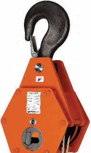
98


99 Renfroe Blocks Bridge Crane Blocks 3 Ton to 50 Ton Made in USA RENFROE SINGLE SHEAVE BRIDGE CRANE BLOCKS W.L.L. Wire Line Sheave O.D. Number Of Hook Throat Tons Size (Inch) Sheaves Opening 3 5/16, 3/8, 7/16, 1/2 8, 10, /8, 7/16, 1/2, 9/16, 5/8 10, 12, /2, 9/16, 5/8, 3/4 12, 14, /2, 9/16, 5/8, 3/4, 7/8 14, /8, 3/4, 7/8, 1 14, 16, RENFROE TWO SHEAVE BRIDGE CRANE BLOCKS W.L.L. Wire Line Sheave O.D. Number Of Hook Throat Center Of Groove To Tons Size (Inch) Sheaves Opening Center Of Groove Options 5 1/4, 5/16, 3/8, 7/16, 1/2 8, 10, , 5.0, 5.5, 6.0, /8, 7/16, 1/2, 9/16, 5/8 10, 12, , 5.75, 6.0, 6.25, 6.5, 7.0, 7.5, /2, 9/16, 5/8, 3/4 12, 14, , 7.0, 7.5, 8.0, 8.5, 9.5, /2, 9/16, 5/8, 3/4 12, 14, , 8.0, 8.5, 9.0, 10.0, 10.5, /2, 9/16, 5/8, 3/4, 7/8 14, 16, 18, , 8.5, 10.0, /16, 5/8, 3/4, 7/8 14, 16, 18, , 9.0, 10.5, /8, 3/4, 7/8, 1 16, 18, , 10.5,
100 DIN Hook Block DIN Hook DIMENSIONS (mm). STRENGTH CLASS - MATERIALS : P-T-V - acc. to DIN SHANK LENGTH : l1 = DIN ; in case of l1 > DIN :contact please 98
 Sheaves (inches) Number (inches) (inches) 3 TON 8 1 1.57 1 26 6 10 1 1.57 1 28 6 12 1 1.57 1 30 6 14 1 1.57 1 32 6 8 2 1.57 1 26 9 10 2 1.57 1 28 9 12 2 1.")
101 Mobile Crane Block Mobile Crane Blocks Available up to 1000 Ton capacity 3 Ton to 50 Ton Made in USA MOBILE CRANE BLOCK DATA SHEAVE Number Hook Throat DIN Approx. Overall Approx. DIA. of Opening Hook Length Thickness (inches) Sheaves (inches) Number (inches) (inches) 3 TON TON
102 Mobile Crane Block Data SHEAVE Number Hook Throat DIN Approx. Overall Approx. DIA. of Opening Hook Length Thickness (inches) Sheaves (inches) Number (inches) (inches) 7.5 TON TON TON TON
103 Mobile Crane Block Data SHEAVE Number Hook Throat DIN Approx. Overall Approx. DIA. of Opening Hook Length Thickness (inches) Sheaves (inches) Number (inches) (inches) 25 TON TON TON
104 Mobile Crane Block Data SHEAVE Number Hook Throat DIN Approx. Overall Approx. DIA. of Opening Hook Length Thickness (inches) Sheaves (inches) Number (inches) (inches) 40 TON TON TON Larger Capacities Available to 1000 Ton. Refer to Hook Dimension Chart. Available in Various Weights / Block Thickness Increases with Weight. 102
105 Block Maintenance And Inspection Renfroe Blocks The following are the minimum suggested maintenance practices we recommend based upon normal use. Product application, environment and use may dictate a more stringent inspection and maintenance program. Inspect for: 1. Wear on pins, axles, rope grooves, side plates, bearings, bushings, and fittings. Excessive wear may be cause to replace parts or remove block from service. 2. Misalignment or wobble in sheaves. 3. Deformation in side plates, pins, axle fitting attachment points. Deformation may be cause to remove block from service. 4. Deformation or corrosion of hook and nut threads. 5. Weld corrosion or weld cracking on welded side plates. 6. Proper fit, deformation and operation of the hook latch. 7. Security of nuts, bolts, and other locking methods, especially after reassembly following a repair or inspection. 8. Deformation and wear of hook. CRANE BLOCK Lubrication Schedule: Lubricate at regular intervals to prevent damage to the bearing. Lubrication intervals are difficult to determine. If plant practice or experience with other applications is not available, consult your lubricant supplier. 103
106 Block Inquiry & Order Form Be sure to make extra copies for future orders. Block Inquiry/Order Form Customer Name Date Address City State/Zip Country Phone Fax Customer Contact Name P.O. Number Inquiry Number For Bridge Crane Blocks Specifications Only Dimensions: A: B: C: For All Block Specifications Sheave Diameter Number of Sheaves Bearing Type Bronze Bushing Roller Bearing Ball Bearing Block Specifications Working Load Limit Wire Rope Diameter (Size) CMMA Rating Lower Fitting Type Single Point Hook Duplex Hook Swivel Hook Latch Other Application Information Overhaul Weight Requirements Lead Line Speed Environment Special Requirements (For Crane Blocks) Special Testing Finish Third Party Inspection or Approval Contact: J.C. RENFROE & SONS Jacksonville, Florida Telephone: 904/ Toll Free: Fax: 904/ COPY & FAX Copyright 2004 J. C. Renfroe & Sons All Rights Reserved 104
107 Block Operator s Manual WARNING: BEFORE PUTTING TOOL IN SERVICE, TAKE THE TOOL OR THIS BOOKLET TO YOUR IMMEDIATE SUPERVISOR. Operator s Manual This Operator s Manual covers the Application, Operation and Maintenance of this RENFROE product. Operator s Manuals for other current RENFROE products are available upon request. Direct requests to J.C. Renfroe & Sons, Jacksonville, Florida
108 Block Operator s Manual THIS PUBLICATION SUPERSEDES ALL PREVIOUSLY PUBLISHED AND/OR DISTRIBUTED INFORMATION BY MANUFACTURER AND/OR ITS DISTRIBUTORS WITH RESPECT TO APPLICABLE RENFROE PRODUCTS AND SUBJECT MATTER DESCRIBED OR CONTAINED HEREIN. WARNING: Prior to selection, operation and/or maintenance of RENFROE products, read and understand the information provided in this manual. The understanding and use of the Definitions are important in determining the limitations and proper application of RENFROE products. Failure to review and utilize recommended applications, operation and maintenance instructions may result in serious injury, or death to operator and others. NOTICE OF EXCLUSION OF WARRANTY RENFROE HAS HEREIN SET FORTH IN CONSPICUOUS LANGUAGE AN EXCLUSION OF ANY WARRANTY EITHER EXPRESSED OR IMPLIED, WHICH IS NOT SPECIFICALLY AND PARTICULARLY CONTAINED HEREIN. PLEASE REFER TO THAT STATEMENT FOR REPRESENTATIONS AND WARRANTIES OF PRODUCTS MANUFACTURED BY J.C. RENFROE & SONS. CRANE BLOCK AND SHEAVE ASSEMBLY WARNING, USE & MAINTENANCE INFORMATION Failure to use this product properly could result in injury or death. Read, understand and follow these instructions to insure the proper use, selection and maintenance of this product A crane block system should be rigged by a qualified person as defined by ANSI/ASME B.30. Instruct workers to keep hands and body away from block sheaves and swivels and away from "pinch points" where rope touches block parts and or loads. Use only genuine Renfroe parts as replacement. Read, understand and follow these instructions to select, use and maintain tackle block systems. When ordering a Renfroe product, the ultimate responsibility for selecting the correct product lies with the end user since only the end user has the knowledge of the application and the environment in which the product will be used. Read these instructions carefully and completely. NEVER side load a Renfroe product. The hook latch must NEVER support the load. Always make sure the hook supports the load. Never use the yielding point of the hook as a gauge of it s capacity. NEVER weld on any Renfroe product. NEVER modify any Renfroe product. WARNING Do not immerse standard Renfroe products in water. In the event the stenciling is worn and not legible or the tag containing the model, capacity or other pertinent information is missing, do no not use block until it has been properly labeled. Renfroe will replace the tag at no charge. 106
109 Block Operator s Manual MODEL: Bridge Crane Block Failure to use this product properly could result in injury or death. Read, understand and follow these instructions to insure the proper use, selection and maintenance of this product. Application Renfroe crane block systems are used in a wide range of applications, each of which has specifications and technical requirements that are unique to that application. When ordering a Renfroe product, the ultimate responsibility for selecting the correct product lies with the end user since only the end user has the knowledge of the application and the environment in which the product will be used. Read these instructions carefully and completely. If you do not understand all words, diagrams, and definitions in this literature contact Renfroe for assistance. Ratings shown in Renfroe literature are based on the products being in a new and unused condition. Features, Advantages and Benefits of a Renfroe Crane Block FEATURES ADVANTAGES BENEFITS Forged Alloy Hook Hook will not break but will Visual sign of overload straighten-out before failure Safety Latch Prevents disconnection from Prevents load hook from anchor point disconnecting when not under load Safety Latch Visual sign of overload Alerts operator to distortion of the hook Shaft lubrication Allows lubrication of sheave bearings Reduced friction promoting fitting without disassembly of crane block increased sheave bearing life Selective Sheave Reliable material quality Correct material for and shaft materials environmental conditions Sheave fleet angle Wide angle of rope lead in Promotes increased life of rope Proof tested Design integrity Assures operation at WLL 107
110 Block Operator s Manual TERMINOLOGY STATIC LOAD - The load resulting from a constantly applied force or load. WORKING LOAD LIMIT The maximum force or mass that the product is authorized to support when used within the guidelines of the severity of service rating. The term applies only to static loads held firmly in direct tension. Working Load Limit is used interchangeably with the following terms: WLL Safe Working Load SWL Resultant Safe Working Load WLL of the Crane Block System The WLL of a Renfroe Block applies only to the block. The WLL of a crane block system can be limited by other parts of the system such as the WLL of the wire rope. PROOF LOAD The average load to which a product may be subjected before visible deformation occurs. PROOF TEST A test applied to a product solely to determine the manufacturing integrity of the product. SHOCK LOAD A significantly increased load factor caused by the sudden shift, jerk or impacting of the load. ULTIMATE LOAD The average load or force at which the product fails, or no longer supports the load. DESIGN FACTOR A theoretical reserve capability; usually computed by dividing the ultimate load by the working load limit. FLEET ANGLE The fleet angle is the angle formed between the rope running to or from the extreme left or right of the drum and a line drawn from the center of the sheave normal to the axis of the drum. (See Illustration A next page) For optimum efficiency, the angle here should not exceed 1 1/2 degrees for a smooth drum, or 2 degrees for a grooved drum. If the fleet angle is larger than the recommended limits, it can cause bad winding on smooth drums and rubbing against the flanges of the grooves. Too small a fleet angle should also be avoided since it will cause the rope to pile up against the flange head. BLOCK A term applied to a wire rope sheave enclosed in side plates and fitted with some attachment such as a hook or shackle. SHEAVE A grooved pulley for wire rope. GROOVES Depressions helical or parallel in the surface of a sheave or drum that are shaped to position and support the rope. TREAD DIAMETER The measurement from the deepest point of the sheave groove on one side of the sheave to the deepest point of the sheave groove on the other side (See Illustration B next page) PITCH DIAMETER A true measurement of the bend of the rope around the sheave WIRE ROPE A plurality of wire strands helically laid about an axis DRUM A cylindrical barrel, either of uniform or tapering diameter, on which rope is wound either for operation or storage; its surface may be smooth or grooved. HOOK SWIVEL The platform from which the hook is housed and suspended from the shaft. SHORT TON The avoirdupois weight on which Renfroe product capacities are based. Commonly used throughout the United States and Canada, the term implies a weight of 2,000 pounds and differs from the long ton, which amounts to 2,240 pounds. METRIC TON A unit of mass equal to 2,205 pounds. 108
111 Block Operator s Manual FLEET ANGLE 2 MAX Illustration A CENTERLINE OF SHEAVE SHEAVE FLEET ANGLE 2 MAX DRUM O.D. P.D. T.D. Illustration B Sheave Diameter and its Effect on Wire Rope Strength. Ratio A Strength Efficiency Compared To Catalog Strength In Percentage When wire rope is bent, it s strength is reduced. Refer to the chart to determine the effect of bend radius on wire rope strength when selecting a sheave diameter. Ratio A: Divide Sheave Dia. by Wire Rope Dia. to find Ratio. Compare this ratio to the table to determine the strength efficiency of the wire rope. Example: = 20 91% strength efficiency compared to catalog strength
112 Block Operator s Manual MAINTENANCE AND INSPECTION Full and total responsibility for inspection, maintenance and the continued use of the product, lies solely with the owner/user. Product application, environment and manner of use may imply a more thorough inspection and maintenance program is needed. It is the responsibility of the owner/user to assure that all government and industry guidelines are met. Inspect for: Wear on pins, axles, rope grooves, side plates, bearings, bushings and fittings. Excessive wear is cause to replace parts or remove block from service. Deformation in side plates, pins, axle fitting attachment points. Deformation is cause to remove block from service. Deformation or corrosion of hook and nut threads. OPERATION Weld corrosion or weld cracking. Hook latch for proper fit, deformation and operation. Security of nuts, bolts and other locking methods, especially after reassembly following a repair or inspection. Check for deformation of hook and for wear. Any hook or fitting with a crack, gouge or distortion should be removed from service immediately. LUBRICATION SCHEDULE: Lubricate at regular intervals to prevent damage to the bearing. Lubrication intervals are difficult to determine. If plant practice or experience with other applications is not available, consult your lubricant supplier. INSTRUCTIONS FOR INSTALLATION, WORKING AND MAINTENANCE General: The present instructions are applicable to wire pulleys and blocks supplied as complete units, either with bearings or bushings. WORKING LOAD LIMIT The maximum force or mass that the product is authorized to support when used within the guidelines of the severity of service rating. The term applies only to static loads held firmly in direct tension. The working Load Limits of this Renfroe product should never be exceeded regardless of the strength of the wire rope being used. The Working Load Limits apply only to new products shipped from the factory. Age, type of service and environmental conditions can subsequently affect these limits, and periodic inspections should be performed to assure the product will perform in accord with existing regulations. Caution: Activities such as, but not limited to, pile driving can have adverse effects upon the life of the product. Inspect your equipment regularly for excessive wear. When using wedge sockets, note that two precautions should be taken. 1. Make sure that a sudden jolt or impact does not dislodge a wedge. When installing wire rope, always pre-load the wedge with wire rope in place. Check frequently to re-tighten or reposition as necessary. 2. Make allowance for the crimping effect common with all types of wedge sockets. Experience shows that it will reduce the Safe Working Limit of a line by 20 percent. 110
113 Block Operator s Manual INSTRUCTIONS FOR SERVICE AND CONTROL OF SHEAVE GROOVES: The sheave grooves of each sheave must be covered by grease before putting them into service. This condition of greasing must be controlled continuously during the working of the crane. This also implies that all the wire ropes must be greased. In order to protect the sheave groove from undue wear, be sure not to allow the fleet angle to exceed 2 degrees. In case you find excessive wear, the sheave must be replaced by a new one. In case of sheaves assembled horizontally, there are holes placed in the cover assemblies. These holes must be cleaned every 3 months in order to avoid water collection in the concavity of these sheaves. The working of the wire rope must be fitted in a way that in the start and the end of each operation, any rope sliding which may cause undue wear of the rope and the sheaves does not happen. You must give a good initial tension to the ropes in order to avoid the axial and the radial deformation in the sheave groove. MODEL SERIAL No. WORKING LOAD LIMIT CABLE SIZE SHEAVE DIA. CLASS LBS. J.C. RENFROE & SONS JACKSONVILLE, FL EXCLUSION OF WARRANTY THERE EXISTS NO WARRANTIES NEITHER EXPRESSED NOR IMPLIED WHICH EXTEND BEYOND THE DESCRIPTIONS OR STATEMENTS CONTAINED IN THE FACE OR ANY PART HEREOF. 111

114 The best safety device on the block Now you can watch your weight with the new weighing hook block that displays to the nearest pound what you're lifting, carrying or weighing. Reassuring? Certainly. Renfroe? Obviously. And you can be assured our weighing blocks feature the same quality, dependability and proof testing as all of our Renfroe products. Accuracy is within 0.1% of the actual load weight.. Failure of a load cell doesn't make the load fall. Large digital display Possibility of transmission of weight via radio to. a remote display, a computer or to a printer. Available for any capacity from 1 ton to 300 tons. No height loss WEIGHING HOOK BLOCK IT LL TAKE A LOAD OFF YOUR MIND J.C. Renfroe & Sons, Jacksonville, Florida Toll Free Fax


115 Load Weighing & Crane Blocks LOAD WEIGHING & MOTORIZED ROTATION CRANE BLOCKS FOR BRIDGE CRANES 1 SHEAVE STANDARD 4 SHEAVE SPECIAL 2 SHEAVE STANDARD 4 SHEAVE 55 TON 4 SHEAVE STANDARD 2 SHEAVE SPECIAL 4 SHEAVE MOTORIZED No Display / Shielded For Foundry Application Weight Transmitted via Radio Signal to Remote Display 6 SHEAVE MOTORIZED ROTATION 113

116 Load Weighing Blocks Fast, accurate weight readings are essential requirements in order for buyers to be assured they are receiving what they ordered. Shippers can verify they are shipping the correct amount of product to their customers to avoid over or under weight shipments. Also you can control material flow within your facility. Available In Capacities 1 Ton to 300 Ton The Weighing Block has the same configuration as a conventional Bridge Crane Block, but it incorporates a highly reliable load cell with a precision of +/- 0.1%. It has a digital display 1 (26mm) tall for easy reading at a distance. It can be supplied with a larger display 1 3/4 or 2 3/8 (45mm/ 60 mm) or a larger 5 (130mm) digital display mounted on the crane within a 300 ft. radius. Advantages: Direct reading of the load weight, avoiding repeated trips to centrally located scales. No head room loss. Compact unit. Totally independent of crane system. Precise load weighing, +/- 0.1% accurate. Electronic components are protected. A failure of the load cell does not release the load, and does not affect the normal operation of the block. Automatic weighing system. Robust design, built for safety. Standard: Interior use, normal environment. Digital screen 1, 1 3/4 or 2 3/8 inch (26, 45 or 60mm) depending on block size. Remote control for functions (ON/OFF, TARE). TARE 100% of nominal load. Totally independent, powered by batteries. Separate battery charger (supplied only with units that have interchangeable batteries). 24 hour battery life for display. Indicator for low battery charge. Optional: Interior use, severe environment, foundry or corrosive atmosphere. Heavy/continuous duty rating. Remote readout, wired or radio. Radio connection to computer or printer. Task memory. Continuous 110, 220 or 380V AC power supplied by cable reel. Maximum tension indicator. Replace that old Bridge Crane Block with a new Load Weighing Block. Work Safer, Know Your Exact Load. 114
117 Renfroe Load Weighing Block RENFROE LOAD WEIGHING BLOCK SINGLE SHEAVE B A C D E Dimensions Needed to Quote A B C D E Wire Rope Diameter Sheave Diameter Overall Length Hook Throat Hook Diameter Block Capacity Tons 115
118 Renfroe Load Weighing Block RENFROE LOAD WEIGHING BLOCK 2 SHEAVE E B C D A Dimensions Needed to Quote A B C D E F Center of Sheave to Center of Sheave Hook Throat Wire Rope Diameter Sheave Diameter Hook Diameter Overall Length 116
119 Renfroe Load Weighing Block RENFROE LOAD WEIGHING BLOCK MOTORIZED ROTATION C A D F B E Dimensions Needed to Quote A B C D E F Center of Sheave to Center of Sheave Hook Throat Wire Rope Diameter Sheave Diameter Hook Diameter Overall Length 117
120 Renfroe Load Weighing Block RENFROE LOAD WEIGHING BLOCK 4 SHEAVE G A C D F (NOT REQUIRED) B E Dimensions Needed to Quote A B C D E F Center of Sheave to Center of Sheave Hook Throat Wire Rope Diameter Sheave Diameter Hook Diameter Overall Length G Outside Sheave Spacing 118


121 Introducing RENFROE s Just as with any Renfroe product, we have our reputation, experience and our proven dependability hanging from every lifting and rigging product we manufacture. And now we re proud to offer a new line of snatch blocks, from hook to shackle to tailboard, featuring the same quality and proof testing, as all of our Renfroe products. Reach for our new snatch block with the reassurance that it s Renfroe. Forged alloy heat-treated hooks and shackles, which will not break but straighten out before failure Openings that allow rope insertion while block is suspended Swivel pin stop will stay in swivel while reeving Safety latch prevents disconnection from anchor point SNATCH BLOCK IT LL TAKE A LOAD OFF YOUR MIND J.C. Renfroe & Sons, Jacksonville, Florida Toll Free Fax
 Opening feature permits insertion of rope while block is suspended Hook and shackle blocks have bolt retaining system to assure no lost bolts For further information")
122 Renfroe Snatch Blocks SNATCH BLOCKS Forged alloy heat treated hooks Forged alloy heat treated shackles Can be furnished with bronze bushings or roller bearings Furnished with hook latch Pressure lube fitting (7 1/2 through 15 Ton) Opening feature permits insertion of rope while block is suspended Hook and shackle blocks have bolt retaining system to assure no lost bolts For further information please contact your nearest Renfroe distributor or J. C. Renfroe & Sons. FEATURES ADVANTAGES BENEFITS Moveable Side Allows rope insertion while hanging Don t have to disconnect and re-connect wire rope Forged Alloy Hook Hook will not break but will straighten out Visual sign of overload before failure Swivel pin stop Pivot pin will stay in swivel while reeving No lost pins Safety Latch Prevents disconnection from anchor point Prevents load hook from disconnecting when not under load Safety Latch Visual sign of overload Alerts operator to bad hook Sheave Pin Diameter Low surface velocity between sheave Promotes longer sleeve bearing life and sheave pin Sheave pin lubrication Allows lubrication of sleeve bearing Reduced friction between sleeve bearing fitting without disassembly of snatch block and sheave pin promoting increased sleeve bearing life Selective Sheave and Reliable material quality Predictable shear properties swivel pin materials Sheave fleet angle Wide angle of rope lead in Promotes increased life of rope Selective side plate Harder material surface Allows Snatch Block use in adverse material conditions Proof tested Product integrity Assures safe operation at WLL 120


123 Renfroe Snatch Blocks SNATCH BLOCKS 121
124 Renfroe Snatch Blocks HOOK ASSEMBLY DIMENSIONS SNATCH BLOCK ASSEMBLY DIMENSIONS 122
125 Renfroe Snatch Blocks SHACKLE ASSEMBLY DIMENSIONS SNATCH BLOCK ASSEMBLY DIMENSIONS 123
126 Renfroe Snatch Blocks TAILBOARD ASSEMBLY DIMENSIONS SNATCH BLOCK ASSEMBLY DIMENSIONS 124
127 Tackle Block Use & Maintenance Information TACKLE BLOCK USE & MAINTENANCE INFORMATION WARNING Failure to use this product properly could result in injury or death. Read, understand and follow these instructions to insure the proper use, selection and maintenance of this product. IMPORTANT Renfroe tackle block systems are used in a wide range of applications each of which has specifications and technical requirements that are unique to that application. NOT FOR LIFTING PERSONNEL!!! When ordering a Renfroe product the ultimate responsibility for selecting the correct product lies with the end user since only he has the knowledge of the application and its environment. Read these instructions carefully and completely. If you do not understand all words and definitions in this literature, call Renfroe for assistance. GENERAL WARNINGS Ratings shown in Renfroe literature are based on the products being in as new condition. Working Load Limit (WLL) ratings indicate the maximum load a product can carry under given operating conditions. Shock loading and other conditions must be taken into account when selecting products for use in tackle block systems. Regular inspections must be conducted to determine whether use can be continued at the Working Load Limit (WLL) stated in the literature, or withdrawn from service. NEVER side load a Renfroe product. The hook latch must NEVER support the load. Always make sure the hook supports the load. NEVER weld on any Renfroe product. NEVER modify any Renfroe product. TERMINOLOGY Static Load - The load resulting from a constantly applied force or weight. Working Load Limit The maximum load that the product is authorized to support in general service. Working Load Limit is used interchangeably with the following terms: WLL Working Load Limit SWL Safe Working Load WLL of the Tackle Block System The WLL of a Renfroe Block applies only to the block. The WLL of a tackle block system can be limited by other parts of the system such as the WLL of the wire rope. Proof Load The average load to which a product may be subjected before permanent deformation occurs; the load applied in the performance of a proof test. Proof Test A test applied to a product solely to determine the conformity of materials and manufacturing to design parameters. Shock Load A sudden increased load caused by the sudden shift, jerk, or impacting of the load. Ultimate Load The average load or force at which the product fails, or no longer supports the load. 125
128 Tackle Block Use & Maintenance Information GENERAL WARNINGS TERMINOLOGY Design Factor A theoretical reserve capability; usually computed by dividing the ultimate load by the working load limit. Short Ton The weight on which Renfroe product capacities are based. Commonly used throughout the United States and Canada, the term implies a weight of 2,000 pounds and differs from the long ton, which amounts to 2,240 pounds. Block A term applied to a wire rope sheave enclosed in side plates and fitted with some attachment such as a hook or shackle. Sheave A grooved pulley for wire rope. Grooves Depressions helical or parallel in the surface of a sheave or drum that are shaped to position and support the rope. Wire Rope A plurality of wire strands helically laid about an axis. MAINTENANCE AND INSPECTION Full and total responsibility for inspection, maintenance and the continued use of the product, lies solely with the owner/user. Product application, environment and manner of use may imply a more thorough inspection and maintenance program is needed. It is the responsibility of the owner/user to assure that all government and industry guidelines are met. Inspect for: Wear on pins, axles, rope grooves, side plates, bearings, bushings and fittings. Excessive wear is cause to replace parts or remove block from service. Misalignment or wobble in sheaves. Deformation in side plates, pins, axle fitting attachment points. Deformation is cause to remove block from service. Deformation or corrosion of hook and nut threads. Weld corrosion or weld cracking. Proper fit, deformation and operation of the hook latch. Security of nuts, bolts and other locking methods, especially after reassembly following a repair or inspection. Deformation of hook and for wear. LUBRICATION SCHEDULE Lubricate at regular intervals to prevent damage to the bearing. Lubrication intervals are difficult to determine. If plant practice or experience with other applications is not available, consult your lubricant supplier. 126

129 NEED IT NOW! GET IT NOW! ROLLER BEARING SWIVELS If you got them any faster, they d have wings! Our Roller Bearing Swivels are proof tested to handle any job, any application. We ll have it winging your way before you hang up the phone! 6 CONFIGURATIONS FOR ANY JOB Eye & Hook Eye & Jaw Eye & Eye Jaw & Hook Jaw & Jaw Jaw & Eye Jacksonville, Florida Fax Toll-Free


130 Renfroe Swivels ROLLER BEARING AND ANGULAR CONTACT BEARING SWIVELS Roller Bearing Swivels Hex Shaped for Maximum Strength Made of Alloy Steel Zinc Plated to Protect from Corrosion Roller Bearings Sealed to Retain Lubricant Angular Contact Bearing Swivels Streamlined Design Designed for High Rotational Speeds and Longer Ropes and Cables Made from Aircraft Grade Steel and Heat Treated for Extra Strength Zinc Plated to Protect from Corrosion Sealed to Retain Lubricant Two or More Angular Contact Ball Bearings 128
131 Renfroe Swivels SWIVEL PART NUMBERS ANGULAR CONTACT BEARING SWL TONS E/H J/H E/J E/E J/J J/E 1/2 ACS0050EH ACS0050JH ACS0050EJ ACS0050EE ACS0050JJ ACS0050JE 3/4 ACS0075EH ACS0075JH ACS0075EJ ACS0075EE ACS0075JJ ACS0075JE 1 1/2 ACS0150EH ACS0150JH ACS0150EJ ACS0150EE ACS0150JJ ACS0150JE 3 ACS0300EH ACS0300JH ACS0300EJ ACS0300EE ACS0300JJ ACS0300JE 5 ACS0500EH ACS0500JH ACS0500EJ ACS0500EE ACS0500JJ ACS0500JE 8 1/2 ACS0850EH ACS0850JH ACS0850EJ ACS0850EE ACS0850JJ ACS0850JE 10 ACS1000EH ACS1000JH ACS1000EJ ACS1000EE ACS1000JJ ACS1000JE 15 ACS1500EH ACS1500JH ACS1500EJ ACS1500EE ACS1500JJ ACS1500JE 35 ACS3500EH ACS3500JH ACS3500EJ ACS3500EE ACS3500JJ ACS3500JE ROLLER BEARING SWL TONS E/H J/H E/J E/E J/J J/E 1/2 ***** ***** RS0050EJ RS0050EE RS0050JJ RS0050JE 5/8 ***** ***** RS0062EJ RS0062EE RS0062JJ RS0062JE 3/4 ***** ***** RS0075EJ RS0075EE RS0075JJ RS0075JE 1 1/2 RS0150EH RS0150JH RS0150EJ RS0150EE RS0150JJ RS0150JE 2 RS0200EH RS0200JH RS0200EJ RS0200EE RS0200JJ RS0200JE 3 RS0300EH RS0300JH RS0300EJ RS0300EE RS0300JJ RS0300JE 5 RS0500EH RS0500JH RS0500EJ RS0500EE RS0500JJ RS0500JE 8 1/2 RS0850EH RS0850JH RS0850EJ RS0850EE RS0850JJ RS0850JE 10 RS1000EH RS1000JH RS1000EJ RS1000EE RS1000JJ RS1000JE 15 RS1500EH RS1500JH RS1500EJ RS1500EE RS1500JJ RS1500JE 129
132 Renfroe Swivels ANGULAR CONTACT BEARING SWIVEL DIMENSIONS H K E J F I D C H K E J H K E J F I D C A A A A A G G F I C D ANGULAR CONTACT BEARING SWIVEL DIMENSIONS SWL TONS A C D E F G H I J K 1/2 7/8 5/16 5/16 1/4 15/32 7/8 3/8 3/8 1/4 3/8 3/4 1 1/4 3/8 19/32 5/16 11/16 31/32 1/2 7/16 3/8 7/16 11/2 1 1/2 7/16 19/32 1/2 13/ /32 9/16 5/8 5/ /8 5/8 3/4 3/4 15/ /32 15/16 13/16 7/8 15/ /16 7/ / /16 1 5/16 1 1/8 1 1/4 1 3/16 81/2 2 7/ /32 1 1/4 2 1/8 2 1/4 1 5/8 1 1/4 1 3/8 1 1/ /8 1 1/2 1 3/4 1 23/32 3 1/ /32 1 3/4 1 5/8 1 13/ /8 1 1/2 1 3/ / /32 1 3/ / /2 1 7/ /8 3 11/16 3 1/4 2 7/8 2 3/8 2 1/4 2 3/ / /4 3 11/ /8 2 3/8 2 1/4 2 3/8 OVERALL LENGTH ALL DIMENSIONS IN INCHES SWL TONS EYE &HOOK JAW & HOOK EYE & JAW JAW & EYE EYE & EYE JAW & JAW 1/2 5 3/8 5 3/8 3 1/8 3 1/8 3 1/8 3 1/16 3/4 7 1/16 7 1/8 4 9/16 4 9/16 4 9/16 4 1/2 1 1/2 7 7/8 7 13/16 5 1/8 5 1/8 5 1/8 5 1/ / /16 7 1/8 7 1/8 7 1/8 7 1/ /4 15 1/4 10 1/2 10 1/2 10 1/2 10 1/2 8 1/2 18 7/8 18 7/8 12 7/ / / / / / / / /4 17 3/4 17 3/4 17 3/ / / / / / / / / / /16 Hook Model Dimensions are to the inside of Hook. 130
133 Renfroe Swivels ROLLER BEARING SWIVEL DIMENSIONS H A K E J G C A L D I G F K H A C E J I F H K A E J C A D I F D L ROLLER BEARING SWIVEL DIMENSIONS TONS A C D E F G H I J K L 2 1 7/8 3/4 13/16 11/16 1 3/8 1 1/ /16 15/ /4 3/4 1 3/4 1 3/8 1 11/32 1 3/16 1 1/ /8 2 1/ / /4 1 11/16 1 1/2 1 1/4 1 1/4 1 1/ /2 3 1/4 1 1/8 1 9/16 1 1/4 2 1/8 2 1/16 1 5/8 1 1/2 1 3/8 1 5/8 3 1/ /2 1 1/4 1 3/4 1 7/16 3 1/8 2 1/4 2 3/8 1 7/8 1 5/8 1 13/16 3 1/ /8 1 3/4 1 15/16 3 1/ /8 1 7/ /8 4 OVERALL LENGTH ALL DIMENSIONS IN INCHES TONS EYE & HOOK JAW & HOOK EYE & JAW JAW & EYE EYE & EYE JAW & JAW 2 8 1/4 8 3/8 8 9/16 8 9/16 8 9/16 8 9/ /8 10 3/8 10 9/ / /8 10 1/ / / / / / /2 17 3/ / / / / / / / / /2 17 1/ /8 18 1/2 18 3/ / / /16 Hook Model Dimensions are to the inside of Hook. 131

134 Always one step ahead where safety matters most Renfroe delivers the load limiter that will not allow an overload to proceed. Reassuring? Certainly. Every Renfroe product has to outperform the specification Preconfigured for desired maximum load Easy to adjust easily installed on fixed end of wire rope Small dimensions Suitable for any EOT crane or lifting device with a fixed end wire rope (new or retrofit) Accuracy within +/- 1% it was designed to meet. That's why you should always say yes to Renfroe. RELIABLY RENFROE! J.C. Renfroe & Sons, Jacksonville, Florida Toll Free Fax

135 Renfroe Load Limiter Load Limiter With Tensiometer The load limiter has been designed to prevent overloads that happen with hoisting equipment using wire rope, such as cranes, bridge cranes, lifts and industrial elevators. Overloads are dangerous and may damage the equipment because the operator is not aware that the load is greater than the working load of the hoisting equipment. The load limiter is manufactured with a flexible steel body that withstands heavy loads. Suitable for any EOT crane or lifting device with a fixed end wire rope (new or retrofit). Perfect for open air installations. Temperature range -22 degrees to 140 degrees Fahrenheit (-30 to +60 Celsius). Accuracy +/- 1%. Dimensionally small and quickly installed without removing the wire rope. Delivered ready to install, preset to your load requirement. Available in cable diameters 3/16 to 1 1/8 (5 to 30 mm). 133

136

137
RENFROE. WARNING: Before putting tool in service, take to your immediate supervisor.
 WARNING: Before putting tool in service, take to your immediate supervisor. RENFROE Model M Clamp Application, Operation and Maintenance Manual OM 211-M Operators Manual This Operator s Manual covers the
RENFROE. WARNING: Before putting tool in service, take to your immediate supervisor.
 WARNING: Before putting tool in service, take to your immediate supervisor. RENFROE Model NM Clamp Application, Operation and Maintenance Manual OM 211-NM Operators Manual This Operator s Manual covers
RENFROE. WARNING: Before putting tool in service, take to your immediate supervisor. Application, Operation and Maintenance Manual Model DWS
 WARNING: Before putting tool in service, take to your immediate supervisor. RENFROE Application, Operation and Maintenance Manual Model DWS OM 211-DWS Operators Manual This Operator s Manual covers the
WARNING: Before putting tool in service, take to your immediate supervisor.
 WARNING: Before putting tool in service, take to your immediate supervisor. RENFROE Model PCK-SL Clamp Application, Operation and Maintenance Manual OM 1011-PCK-SL Operators Manual This Operator s Manual
RENFROE. WARNING: Before putting tool in service, take to your immediate supervisor. Model SCSL Clamp Application, Operation and Maintenance Manual
 WARNING: Before putting tool in service, take to your immediate supervisor. RENFROE Model SCSL Clamp Application, Operation and Maintenance Manual OM 311 SCSL Operators Manual This Operator s Manual covers
WARNING: Before putting tool in service, take to your immediate supervisor. Model TL/A Clamp Application, Operation and Maintenance Manual
 WARNING: Before putting tool in service, take to your immediate supervisor. RENFROE Model TL/A Clamp Application, Operation and Maintenance Manual OM 211-TL/A Operators Manual This Operator s Manual covers
WARNING: Before putting tool in service, take to your immediate supervisor.
 WARNING: Before putting tool in service, take to your immediate supervisor. RENFROE Model NMBL Clamp Application, Operation and Maintenance Manual OM NMBL 0809 Operators Manual This Operator s Manual covers
Safety Clamps, Inc. Big Bite Lifting Clamps. HL-Lock Model Clamp
 Big Bite Lifting Clamps Operation, Maintenance, and Repair Manual Clamp Warning Prior to operating your Safety Clamp, please ensure that All operators read and understand this manual. Effective May 1,
Incremental Lifting System
 Synchronously Lift and Mechanically Hold Incremental Lifting System JS-Series, Jack-Up Systems JS-Series, Jack-Up Systems Shown: JS-250-Series Jack-Up System (one lifting tower shown) Incremental Lifting
Incremental Lifting System
 Synchronously Lift and Mechanically Hold Incremental Lifting System JS-Series, Jack-Up Systems JS-Series, Jack-Up Systems JS-250, Enerpac Jack-Up System (one lifting tower shown) Incremental Lifting System
600 SERIES STANDARD DUTY STRAIGHT TRACK INSTALLATION INSTRUCTIONS
 600 SERIES STANDARD DUTY STRAIGHT TRACK INSTALLATION INSTRUCTIONS PLEASE READ INSTRUCTIONS THOROUGHLY BEFORE BEGINNING. A. BI-PARTING TRAVEL 1. Before raising track into position, determine location of
The Caldwell Group Fax
 LIFTING BEAMS 8 Lifting Beams Model 20 Low Headroom Multiple Spread Lifting Beam Ideal where headroom is limited Beams over 4 have 3 spreads (3 & 4 beams have 2 spreads). Swivel hooks with hook latches
Ph: Camlok. Lifting Clamps. Made in Britain - Safely used throughout the world.
 Ph: 02 9631 8833 camlok@lbwireropes.com.au Camlok Made in Britain - Safely used throughout the world www.camlok.com.au Product Page Vertical Plate Clamps: Why a Camlok: The Advantages Explained 3 92 Series
Below the Hook Lifting
 SECTION INDEX S E C T I O N 1 3 BALE LIFTING TONG...-14 BARRIER GRABS...- 14 BEAM TONGS...-14 BEAM, SPREADER Adjustable...-4 Custom...-5 Fiberglass...-4 Fixed...-3 BEAMS, LIFTING Adjustable Hook...-1 Custom...-5
STANDARD SHAPES TROLLEY PARTS MANUAL
 STANDARD SHAPES TROLLEY PARTS MANUAL, Unified Industries, Inc. All Rights Reserved. www.unified-ind.com PARTS AND REPAIR MANUAL This manual has been compiled to expedite the ordering of repair parts for
The Caldwell Group Fax
 Model 82NC - Narrow Coil C Hook *Will not hang level when empty. Center of gravity must be centered under crane hook to prevent tilting of the lifter & load. Handles narrow coils with less coil edge damage.
Lattice Boom Crawler Crane 50-ton (50 mt)
") Lattice Boom Crawler Crane 50-ton (50 mt) 50 tons (50 mt) at an 11' (3.35 m) radius 16,800 lbs (7 620 kg) clam & drag ratings with 70' (21.34 m) of boom 140' (42.67 m) conventional angle boom and 110'
Lattice Boom Crawler Crane 50-ton (50 mt) 50 tons (50 mt) at an 11' (3.35 m) radius 16,800 lbs (7 620 kg) clam & drag ratings with 70' (21.34 m) of boom 140' (42.67 m) conventional angle boom and 110'
For more than 25 years
 For more than 25 years More performance. More options. More value. We can move it! No matter how much, how fast or how far you need to lift, pull or position, our promise to you is very simple: WE CAN
Hoists & Rigging Products for Construction Projects
 Manual Hoists Have a special application? Our full line of material handling products allows us to create complete solutions rather than just offering single products. Now you have one point of contact
SERIES. 80 U.S. ton 72.6 metric ton Lattice Boom Crawler Crane
 80 U.S. ton 72.6 metric ton Lattice Boom Crawler Crane SERIES Cutting edge winch package with wet brake design and matching front & rear drums 3-piece counterweight system, designed with innovative counterweight
for CONSTRUCTION PROJECTS HOISTS & RIGGING PRODUCTS FOR CONSTRUCTION Power Plants Commercial Construction Wind Energy Bridges & Highways
 A Complete Line of Products & Solutions for CONSTRUCTION PROJECTS HOISTS & RIGGING CONSTRUCTION Power Plants Commercial Construction Wind Energy Bridges & Highways TOUGH. RELIABLE. STRONG. Keeping Projects
PART # DESCRIPTION 3670 ROLLER SEALER ASSY CARD ASSY - STA CONT 5412 GUIDE REAR INSERT CABLE CONTACT SPRING VALVE
 PART # DESCRIPTION 3670 ROLLER SEALER ASSY 59319 4517 CARD ASSY - STA CONT 5412 GUIDE REAR INSERT 13506 CABLE 14213 CONTACT SPRING 17914 VALVE SOLENOID 24 VDC 20571 SWITCH ASSY 21370 327 BULB WEDGE BASE
MATERIALS HANDLING MATERIALS HANDLING
 7 MATERIALS HANDLING SPREADER BAR END CAPS & EQUALISERS...142 SPREADER BARS...143 CONTAINER LIFTERS 20 & 40FT...144 PERSONNEL WORK CAGES...145 LOAD ROLLERS & LOAD SKATES...146 HAND PALLET TRUCK & LIFTING
The Caldwell Group Fax
 Model 82NC - Narrow Coil C Hook *Will not hang level when empty. Center of gravity must be centered under crane hook to prevent tilting of the lifter & load. Handles narrow coils with less coil edge damage.
COUNTER SHAFT NUT LOCKING PLATE 1 $ HOIST DRUM CLUTCH EYE BOLTS 1 $ LEFT DRUM CLUTCH THREADED PIN 2 $ 138.
 1 2184 PULLEY FOR RADIATOR FAN 1 $ 326.25 2 2184 PULLEY FOR RADIATOR FAN 1 $ 326.25 3 3331 REAR DRUM BRAKE RETURN SPRING 5 $ 51.31 5 10285 LEFT REAR DRUM BRAKE AIR CAN REACH ROD ( LONG ROD ) 1 $ 85.12
250 ton (226.8 mt) Lattice Crawler Crane
 Lattice Crawler Crane") 250 ton (226.8 mt) Lattice Crawler Crane 365 hp Tier III Engine Transport weight is 87,100lbs with carbody, live mast with self assemble cylinder, and hoist rope HSL counterweight removal system, lowers
250 ton (226.8 mt) Lattice Crawler Crane 365 hp Tier III Engine Transport weight is 87,100lbs with carbody, live mast with self assemble cylinder, and hoist rope HSL counterweight removal system, lowers
Material Handling Overview
 MATEIAL HANDLING Overview All rental equipment is throughout North America. Overview For specific product information, refer to the group of equipment within this section s overview on the following page
RAIL MATERIAL HANDLING TONGS RAIL IPS 40 TONGS FROG LIFTING IPS 43
 INDEX 40 51 TONGS RAIL IPS 40 THREADING TONGS & SPREADER BARS RAIL IPS 42 TONGS FROG LIFTING IPS 43 TONGS SLEEPER/TIMBER IPS 44 PULLER & TUGGER RAIL IPS 45 THREADER BALL & RAIL IPS 46 RUNNER & THREADER
Please make your selections below to view, search or print ACCO Material Handling Solutions WRIGHT SPEEDWAY and WRIGHT WORK-RATED product pages.
 Contact Information Welcome! Please make your selections below to view, search or print ACCO Material Handling Solutions WRIGHT SPEEDWAY and WRIGHT WORK-RATED product pages. 1T to 5T THE NEW CENTURY SERIES
Series 1400A Hydraulic Crane 33 Ton
 Series 1A Hydraulic Crane 33 Ton Load Ratings DANGER AN UNTRAINED OPERATOR SUBJECTS HIMSELF AND OTHERS TO DEATH OR SERIOUS INJURY YOU MUST NOT OPERATE THIS CRANE UNLESS You have been trained in the safe
Series 1400 Hydraulic Crane 33 Ton Load Ratings
 Series 1 Hydraulic Crane 33 Ton Load Ratings! DANGER AN UNTRAINED OPERATOR SUBJECTS HIMSELF AND OTHERS TO DEATH OR SERIOUS INJURY YOU MUST NOT OPERATE THIS CRANE UNLESS You have been trained in the safe
WORK STATION JIB CRANES CAPACITIES: TRACKS: PRODUCTIVITY: Up to 2000 lbs Steel, Aluminum & Stainless Steel Average 28% increase
 WORK STATION JIB CRANES CAPACITIES: TRACKS: PRODUCTIVITY: Up to 2000 lbs Steel, Aluminum & Stainless Steel Average 28% increase Work Station Jib Cranes Versatile enough to perform a wide variety of local
WORK STATION JIB CRANES CAPACITIES: TRACKS: PRODUCTIVITY: Up to 2000 lbs Steel, Aluminum & Stainless Steel Average 28% increase
 WORK STATION JIB CRANES CAPACITIES: TRACKS: PRODUCTIVITY: Up to 2000 lbs Steel, Aluminum & Stainless Steel Average 28% increase Optional Accessories Festoon Clamps Festoon clamps anchor the festooning
P Series Puller 1000 and 2000 lb Capacity
 P Series Puller 1000 and 2000 lb Capacity Features / Wire Puller: 4:1 design factor. Meets SM 30.21. Handle and frame are heavy gauge steel with rivet construction and slip-resistant grip. ll steel parts
Cranes. Range Diagram and Lifting Capacity RT345-1XL 45 TON LIFTING CAPACITY RANGE DIAGRAM 33.75' - 105' BOOM
 Range Diagram and Lifting Capacity RT345-1XL Cranes 45 TON LIFTING CAPACITY RANGE DIAGRAM 33.75' - 105' BOOM DIMENSIONS ARE FOR LARGEST FACTORY FURNISHED HOOK BLOCK AND HOOK & BALL, WITH ANTI-TWO BLOCK
More performance. More options. More value.
 More performance. More options. More value. WE CAN MOVE IT. We can supply a stock unit, modify a standard model or design and manufacture a completely custom product for your application. Our Columbia
SBRL-SERIES SPREADER BEAMS INSTRUCTION MANUAL
 VESTIL MANUFACTURING CORP. 2999 North Wayne Street, P.O. Box 507, Angola, IN 46703 Telephone: (260) 665-7586 -or- Toll Free (800) 348-0868 Fax: (260) 665-1339 www.vestilmfg.com e-mail: info@vestil.com
WORK STATION BRIDGE CRANES & MONORAILS FREE STANDING & CEILING MOUNTED CAPACITIES FROM 250 TO 4000 LBS
 WORK STATION BRIDGE CRANES & MONORAILS FREE STANDING & CEILING MOUNTED CAPACITIES FROM 250 TO 4000 LBS PRE-ENGINEERED COMPONENTS LodeRail is a complete crane system. The wide variety of components makes
MAINTENANCE EQUIPMENT CATALOG DC000048EN/21
 MAINTENANCE EQUIPMENT CATALOG DC000048EN/21 TOOL CASE FOR STATION MOUNTING LOCATIONS IN THE STAION TOOL CASE FOR MAINTENANCE EQUIPMENT IN THE STATION 41080402 23/02/2017 2 GRIP NON SLIDING CONTROL DEVICE
Mechanical Vacuum Lifters
 Self-Powered, Self-Cycling Mechanical Vacuum Lifters The Leading Sheet & Plate Lifters in North America Since 1968 The Unique Design Allows You to Attach to Any Crane Hook and Lift Made in USA by ANVER
BIRDS SAFETY CLAMPS. How to read model numbers: (A) HCO signifies narrow jaw opening (see spec. chart); HCO signifies wide jaw opening.
 HCO signifies narrow jaw opening (see spec. chart); HCO signifies wide jaw opening.") Plate lamps IRS SFTY LMPS Safety lamps - apacities and Specifications ow to read model numbers: () signifies narrow jaw opening (see spec. chart); signifies wide jaw opening. lamp 0.5 tonne () 2 0-34 33
Plate lamps IRS SFTY LMPS Safety lamps - apacities and Specifications ow to read model numbers: () signifies narrow jaw opening (see spec. chart); signifies wide jaw opening. lamp 0.5 tonne () 2 0-34 33
SINGLE WIDE MASTER CATALOG GOSS COMMUNITY UNIT GOSS COMMUNITY FOLDER
 SINGLE WIDE MASTER CATALOG GOSS COMMUNITY UNIT GOSS (Click on the name to be taken to that section) Stocking Manufacturer of Quality Replacement Parts (815) 965-0884 Fax (815)965-1049 Welcome to the Quality
BT 3870 BOOM TRUCK CRANE BT Features:
 BOOM TRUCK CRANE Data Sheet - Imperial Features: Capacity at rated distance from center of rotation: 19 T @ 5 ft Maximum boom length: 70 ft Maximum tip height: 80 ft Optional Single Stage 24 ft or 24-40
IDENTIFYING CWP MAIN RO PUMP REPLACEMENT PARTS
 IDENTIFYING CWP MAIN RO PUMP REPLACEMENT PARTS The purpose of this Technical Update is to understand and identify the various parts required to replace the Main RO pump on the CWP. There are approximately
HC 60. Hydraulic Crawler Crane. simple, available and cost effective FEATURES
 HC 60 Hydraulic Crawler Crane FEATURES 60 tons (54.4 mt) max lift capacity 160 ft. (48.8 m) max lift crane boom length 130+40 ft. (39.6+12.2 m) max lift crane boom & jib length Power up/down and freefall
Company Profile. Our parent Company. KWS A member of the THIELE-Group
 G r a d e 8 0 GK8 by THIELE Company Profile Our parent Company The company was founded in 935 by August Thiele. Chains were even welded in forge with only 8 employees. Later on automatic bending and welding
TECHNICAL MANUAL UNIT, INTERMEDIATE DIRECT SUPPORT AND INTERMEDIATE GENERAL SUPPORT MAINTENANCE MANUAL
 TM 5-3820-256-24-1 TECHNICAL MANUAL UNIT, INTERMEDIATE DIRECT SUPPORT AND INTERMEDIATE GENERAL SUPPORT MAINTENANCE MANUAL DRILLING SYSTEM, WELL, ROTARY, TRUCK MOUNTED, AIR TRANSPORTABLE, 600 FEET CAPACITY
LIFT TRUCKS FOR EVERY APPLICATION
 LIFT TRUCKS FOR EVERY APPLICATION Container ports and terminals Intermodal and barge handling Steel and aluminum Mining General manufacturing Pulp & paper, wood Automotive Wind power Oil & gas Nuclear
HOISTS RATCHET LEVER HOISTS
 Yale HOISTS RATCHET LEVER HOISTS Yale PE & RS Ratchet Lever Hoist / to ton capacities Link chain models Light and portable Weatherized load brake Requires less handle pull to lift full load Efficient Yale
FF3000 PORTABLE FLANGE FACER
 FF3000 PORTABLE FLANGE FACER FEATURES SETUP & OPERATION COMPONENTS & ACCESSORIES TECHNICAL DATA Compact, lightweight, and easy to set up. Compact and Versatile Patented, low profile machine is one of the
PowerTrak. Curtain/Vent Actuator. Hired Hand Manufacturing, Inc Co Rd 68 PO Box 99 Bremen, Alabama 35033
 PowerTrak Curtain/Vent Actuator Hired Hand Manufacturing, Inc. 1733 Co Rd 68 PO Box 99 Bremen, Alabama 35033 Part No. 4801-0154 Rev 8-07 Owner's Manual PowerTrak Table of Contents 1. Ratings and specifications...3
Optional Bullard Hook* with return latch, with or without return spring, for added safety.
 Standard Top Hook with safety latch-rigid (standard) or swivel. Optional Bullard Hook* with return latch, with or without return spring, for added safety. Optional Shur-Loc Hook* with positive lock latch
Vertical Clamps - TS. Pricelist :
 Vertical Clamps - TS - For vertical lifting and transporting of steel plates and structures. - The TS/STS lifting clamps are equipped with a safety mechanism, ensuring the clamp does not slip when lifting
Range Diagram and Lifting Capacity T Cranes RANGE DIAGRAM BOOM
 Range Diagram and Lifting Capacity T340-1 Cranes RANGE DIAGRAM 30-94 BOOM Dimensions are for largest factory furnished hook block and hook & ball, with anti-two block activated COUNTER WEIGHT BOOM LENGTH
COLUMBUS McKINNON CORPORATION
 COLUMBUS McKINNON CORPORATION Our signature Yale Global King and Shaw-Box World Series electric wire rope hoists are now available with one of the industry s premier variable frequency drives. Manufactured
CROSSOVER 4500L. 45T capacity class Boom Truck Crane Datasheet imperial. View thousands of Crane Specifications on FreeCraneSpecs.com.
 45T capacity class Boom Truck Crane Datasheet imperial Features 45 ton rated capacity @ 9 ft from center of rotation 129 ft maximum boom length 136 ft maximum tip height 32/49 ft optional jib 183 ft maximum
CROSSOVER Datasheet imperial. Boom Truck Crane 60T capacity class. Features
 Boom Truck Crane T capacity class Datasheet imperial Features tons @ 10 capacity at rated distance from center of rotation 110 maximum boom length 115 maximum tip height 32/57 optional jib 1 maximum sheave
Enerpac Hydraulic Presses
 Enerpac Hydraulic es Enerpac Hydraulic es are available in a variety of capacities and sizes. The press frames are designed for maximum strength and durability. Strong frames and powerful high-pressure
MARCY SMITH MACHINE SM Model SM Retain This Manual for Reference OWNER'S MANUAL
 NOTE: Please read all instructions carefully before using this product Table of Contents Safety Notice Hardware Pack Assembly Instruction MARCY SMITH MACHINE SM-4008 Parts List Warranty Ordering Parts
130-ton (117.6 mt) Lattice Boom Crawler Crane
 Lattice Boom Crawler Crane") 130-ton (117.6 mt) Lattice Boom Crawler Crane Transports with crawlers, rope and base 119,200 lbs (54 069 kg) with side frames 73,399 lbs (33 294 kg) without side frames Free-fall wet brake winches w/automatic
130-ton (117.6 mt) Lattice Boom Crawler Crane Transports with crawlers, rope and base 119,200 lbs (54 069 kg) with side frames 73,399 lbs (33 294 kg) without side frames Free-fall wet brake winches w/automatic
WIELAND-DAVCO CORPORATION CRITICAL LIFT PERMIT. Subcontractor: Subcontractor Lift Supervisor: (This individual must be present during the lift)
") WIELAND-DAVCO CORPORATION CRITICAL LIFT PERMIT Section 1: Approvals and Documentation A. Identification Subcontract Number: Location: Lift Identification Name: Date of Lift: Time: Lift Description: B.
WIELAND-DAVCO CORPORATION CRITICAL LIFT PERMIT Section 1: Approvals and Documentation A. Identification Subcontract Number: Location: Lift Identification Name: Date of Lift: Time: Lift Description: B.
Services. Rental Equipment RENTAL DIVISION PRODUCT LINES. LOAD RESTRAINTS Load Binders (Lever & Ratchet) Truck Tie-down Assemblies Boomer Chains
 Truck Tie-down Assemblies Boomer Chains") RENTAL DIVISION PRODUCT LINES In a continuing effort to give the customer the opportunity to get an assortment of equipment, services and products from one supplier, our rental division was established
RENTAL DIVISION PRODUCT LINES In a continuing effort to give the customer the opportunity to get an assortment of equipment, services and products from one supplier, our rental division was established
RAIL MATERIAL HANDLING TONGS RAIL IPS 40 TONGS FROG LIFTING IPS 43
 INDEX 40 51 TONGS RAIL IPS 40 THREADING TONGS & SPREADER BARS RAIL IPS 42 TONGS FROG LIFTING IPS 43 TONGS SLEEPER/TIMBER IPS 44 PULLER & TUGGER RAIL IPS 45 THREADER BALL & RAIL IPS 46 RUNNER & THREADER
HV-20/35 Series Proportioning Unit
 "Success through Unity" HV-20/35 Series Proportioning Unit Parts Identification Manual 63942-ID June 30, 2003 Issue 1 GUSMER CORPORATION A Subsidiary of Gusmer Machinery Group, Inc. One Gusmer Drive Lakewood,
400 SERIES STANDARD DUTY STRAIGHT TRACK INSTALLATION INSTRUCTIONS
 400 SERIES STANDARD DUTY STRAIGHT TRACK INSTALLATION INSTRUCTIONS PLEASE READ INSTRUCTIONS THOROUGHLY BEFORE BEGINNING. A. BI-PARTING TRAVEL BATTEN INSTALLATION 1. Place track either on the floor or on
SECTION 12. Lifting & Spreader Beams
 SECTION Lifting & Spreader Beams Lifting beams and spreader bars are below the hook equipment that facilitates safe lifting by spreading the attachment points and allowing for better sling angles. Even
G W DISCONTINU. SERVICE TOOLS for COMPANIES, INC. HEAVY DUTY TRUCK TRANSMISSIONS AXLES TIMING BLOCKS gwtoolco.com
 G & TOOL W SERVING THE GEAR INDUSTRY OVER 45 YEARS COMPANIES, INC. SERVICE TOOLS for HEAVY DUTY TRUCK TRANSMISSIONS AXLES (FULLER T-9824) G-38: INPUT SHAFT BEARING PULLER Countershaft Front Bearings (#81007)
Yale HOISTS. 414 West Broadway Ave. P.O. Box 769 Muskegon, MI PH: FX:
 Yale HOISTS! To Avoid Injury: Do not exceed working load limit, load rating, or capacity. Do not use to lift people or loads over people. Read and follow all instructions. 44 West Broadway Ave. P.O. Box
Heavy Equipment & Rigging Specialist Training
 Heavy Equipment & Rigging Specialist Training Module 3 Unit 1: Crane Load Chart Basics 23Mar08 1 Unit Objective After completion of this unit, you will be able to deploy a mobile crane safely and efficiently
RIG-I-FLEX 140 SERIES CURTAIN TRACKS
 RIG-I-FLEX 140 SERIES CURTAIN TRACKS Parts Included 140 RIG-I-FLEX CWANA code CORD OPERATED/MOTORIZED WALK-ALONG 140 (240) 140-R (240-R) 141 (241) 141-R (241-R) 142 (242) 142-R (242-R) STRAIGHT CURVED
About Our Blocks. Section 2. Tip!
 About Our Blocks Sheave Materials Nylatron GS sheaves with molded grooves are available in eight inch (nominal) diameter for 3/4" manila rope and 1/4" wire rope. Nylatron GSM sheaves with machined grooves
Jib Cranes Commerce Pkwy., Auburn Hills, Michigan Ph: (248)
") Jib Cranes Index Introduction Overview...1 Jib Crane Series Hose Management... Accesories... 2 3 Knight Global l Warranty Information Knight warrants that its products and parts shall meet all applicable
Jib Cranes Index Introduction Overview...1 Jib Crane Series Hose Management... Accesories... 2 3 Knight Global l Warranty Information Knight warrants that its products and parts shall meet all applicable
Toll-free:
 Toll-free: 1.800.362.4601 CRANES CRANE SERVICE WIRE ROPE ENGINEERED PRODUCTS HARDWARE SLINGS TRAINING CAPABILITIES BROCHURE >> www.progressivecrane.com Cranes: Progressive Crane is a leading manufacturer
ELECTRIC CHAIN HOIST ED SERIES
 EFFECTIVE: October 8, 2014 ELECTRIC CHAIN HOIST ED SERIES 125 through 525 Lb. Capacity Code, Lot and Serial Number This equipment should not be installed, operated or maintained by any person who has not
Lineman s Hoists Cable Hoists Ratchet Lever Hoists Wire Grips
 Lineman s Hoists Cable Hoists Ratchet Lever Hoists Wire Grips Extra Measure of Reliability Fiberglass Handle and Polyester Webbing Provides added nonconductive material when using proper hot line handling
Rev. 10/27/2015 CDL-2000, MANUAL
 VESTIL MANUFACTURING CORP. 2999 North Wayne Street, P.O. Box 507, Angola, IN 46703 Telephone: (260) 665-7586 Toll Free (800) 348-0868 Fax: (260) 665-1339 www.vestilmfg.com e-mail: sales@vestil.com CDL-2000
Max. Lifting Capacity: 100 US Tons Max. Boom Length: 200 ft Max. Boom + Jib Length: 190 ft + 60 ft
 HYDRAULIC CRAWLER CRANE Max. Lifting Capacity: 100 US Tons Max. Length: 200 ft Max. + Jib Length: 190 ft + 60 ft SPECIFICATIONS FOR CK1000-III CRAWLER CRANE The Kobelco CK1000-III Crawler Crane is designed
HC 50. Hydraulic Crawler Crane. simple, available and cost effective FEATURES
 HC 50 Hydraulic Crawler Crane FEATURES 50 tons (45.4 mt) max lift capacity 160 ft. (48.8 m) max lift crane boom length 130+40 ft. (39.6+12.2 m) max lift crane boom & jib length Power up/down and freefall
RT130 ROUGH TERRAIN CRANE DATASHEET - IMPERIAL. Features: Rated capacity: ft working radius. Maximum boom length: 155 ft
 ROUGH TERRAIN CRANE DATASHEET - IMPERIAL Features: Rated capacity: 130 ton @ 10 ft working radius Maximum boom length: 155 ft Maximum tip height: 164 ft CONTENTS Key............................................................................................
Mechanical Hoists. Catalog 1100 July Hoists - Mechanical Phone: Web: hubbellpowersystems.
 Mechanical Hoists Catalog 1100 Page 1101 RATCHET HOISTS User-friendly operation and construction. Experienced operators prefer CHANCE lever hoists for longterm, dependable performance. Light-weight for
Range Diagram and Lifting Capacity T Cranes. View thousands of Crane Specifications on FreeCraneSpecs.com RANGE DIAGRAM BOOM
 Range Diagram and Lifting Capacity Cranes RANGE DIAGRAM 30-94 BOOM Dimensions are for largest factory furnished hook block and hook & ball, with anti-two block activated COUNTER WEIGHT BOOM LENGTH UPPERSTRUCTURE
RT555 TEREX. rough terrain crane 55 ton capacity. range diagram & lifting capacities. Range Diagram ( boom) HOOK BLOCK WEIGHTS
 HOOK BLOCK WEIGHTS") TEREX RT5 rough terrain crane ton capacity range diagram & lifting capacities DIMENSIONS ARE FOR LARGEST FACTORY FURNISHED HOOK BLOCK AND HOOK & BALL, WITH ANTI-TWO BLOCK ACTIVATED Range Diagram (33-1
TEREX RT5 rough terrain crane ton capacity range diagram & lifting capacities DIMENSIONS ARE FOR LARGEST FACTORY FURNISHED HOOK BLOCK AND HOOK & BALL, WITH ANTI-TWO BLOCK ACTIVATED Range Diagram (33-1
MINING PRODUCTS FOR HOISTS & RIGGING. Manual Hoists. Chain & Rigging Attachments. Specialized Attachments. Liner Bolts. for THE MINING INDUSTRY
 A Complete Line of Products & Solutions for THE MINING INDUSTRY HOISTS & RIGGING PRODUCTS FOR MINING Manual Hoists Chain & Rigging Attachments Specialized Attachments Liner Bolts Columbus McKinnon Family
ADVANCED SPOOLING TECHNOLOGY LEBUS KNOWS HOW
 ADVANCED SPOOLING TECHNOLOGY LEBUS KNOWS HOW RENOWNED THROUGHOUT THE WORLD FOR ITS EXPERIENCE AND OUTSTANDING SPOOLING TECHNOLOGY LEBUS WILL HELP YOU WIND UP ALL YOUR PROBLEMS. THE ORIGINAL LEBUS SPOOLING
Overhead Products. Overhead Products Introduction. Model Q Lasher. Eagle Lasher Series Series
 Introduction In 2006, DCD Design took on the Spinning Equipment Company and began producing the Lineman and Eagle cable lashers. In doing so, DCD took on a long history of quality and innovation. These
STRAIN LINK STICK ROLLER LINK STICK ADJUSTABLE STRAIN POLES SPIRAL LINK STICK TRANSMISSION TOOLS
 172 Phone: 800-323-6606 Fax: 847-488-1285 www.hilineco.com STRAIN LINK STICK Used as insulation between rope blocks and a hot line wire grip For deadend structures and running corners Attached to conductor
Cranes. Range Diagram and Lifting Capacity RT TON LIFTING CAPACITY RANGE DIAGRAM 33' - 110' BOOM
 Range Diagram and Lifting Capacity Cranes 55 TON LIFTING CAPACITY RANGE DIAGRAM 33' - 110' BOOM Dimensions are for largest factory furnished hook block and hook & ball, with anti-two block activated COUNTER
HSpecialties Inc. TABLE OF CONTENTS
 TABLE OF CONTENTS Introduction... Curtain Track Selection Guide...2 Ordering COMPLETE Tracks...3 00 Series Standard-Duty Straight Track...4 200 Series Black Medium-Duty Straight Track...8 300 Series Standard-Duty
Cranes. Piggy Backs. Parts. Service. Whatever your needs, give us a call Or Toll Free at
 Cranes Piggy Backs Parts or Service Whatever your needs, give us a call. 816-524-3600 Or Toll Free at 800-398-7826 Table of Contents Carts & Casters 1 & 2 Drywall Protectors 3 Cargo Security 4 Miscellaneous
Installation manual. Pole-mount Deployment System
 Installation manual Pole-mount Deployment System 974-80207001/2.0 Pole-mount Deployment System Installation Manual Document revisions Version Date Written by Checked by Approved by 1.0 Aug 25, 2011 BC
Power Workholding. Power Workholding n Precision Vises n Zero Point Mounting n Assembly and Handling
 Power Workholding Power Workholding n Precision Vises n Zero Point Mounting n Assembly and Handling OUR STORY In 1982 an independent joint venture was established to marry the proven product expertise
classification scheme. Subject matter covered by these groups is classified in the following ECLA groups:
 B66F HOISTING, LIFTING, HAULING OR PUSHING, NOT OTHERWISE PROVIDED FOR, e.g. DEVICES WHICH APPLY A LIFTING OR PUSHING FORCE DIRECTLY TO THE SURFACE OF A LOAD ({invalid lifting devices A61G 7/10; } mounting
GLOBAL KINGTM &WORLD SERIESTM
 GLOBAL KINGTM &WORLD SERIESTM ELECTRIC WIRE ROPE HOISTS COl UMBUS McKINNON CORPORATION -48 QUICK SHIP PROGRAM IS EVEN IBLE Since its launch, the Flex-48 Quick Ship Program has proven to be a reliable and
ST400 Series. Features/Benefits. Versatile. ST1000/1000M Series. Industry Applications:
 ST1000/1000M Series 1 For engine displacement of: Diesel 300 to 3600 CID (5 to 60 liters) Features/Benefits Efficient 26 hp turbine motor uses no external lubrication One Hose Hookup simplifies required
Pillar and wall-mounted slewing jibs and cranes. Workplace efficiency improvement with the Demag crane range
 Pillar and wall-mounted slewing jibs and cranes Workplace efficiency improvement with the Demag crane range System components and installations As a pioneer in overhead materials handling, Demag Cranes
Color-Coded Polymer Pistol Grip, Valve Handle Covers offer rugged durability in harsh fi refi ghting conditions
 Domestic Catalog G-Force Nozzles: The Inside Story Based on a highly customizable global nozzle platform design, the unique G-Force series of fi xed, selectable, and automatic nozzles combine over 40 years
TOOLS THAT WORK WITH YOU
 TOOLS THAT WORK WITH YOU JAVELIN FABRICATION TOOLS EDITION 18 Easy to use, well designed and they last forever. That s how I would describe the Javelin stands and rollers. I have had the same stands for
Shipping Systems Division
 Shipping Systems Division Keeping you and your load secure is our job! We do this by manufacturing a blend of field-proven products to developing some of the industry s most innovative new systems for
Carbon Fiber Air Shafts. Custom Carbon Fiber Tubes
 Carbon Fiber Air Shafts Lightweight composite air shafts... with custom performance by design. NimCor offers an outstanding line of precision engineered carbon fiber shafts with unique performance features.
WORK STATION BRIDGE CRANES
 FREE STANDING WORK STATION BRIDGE CRANES CAPACITIES: SPANS: ENCLOSED TRACKS: PRODUCTIVITY: Up to 4000 lbs Up to 30' Steel, Aluminum & Stainless Steel Average 28% Increase A Class Above... In Productivity.