MARCY SMITH MACHINE SM Model SM Retain This Manual for Reference OWNER'S MANUAL
|
|
|
- Stella Golden
- 5 years ago
- Views:
Transcription
 999-8899 Fax: (626) 961-9966 www.impex-fitness.")
1 NOTE: Please read all instructions carefully before using this product Table of Contents Safety Notice Hardware Pack Assembly Instruction MARCY SMITH MACHINE SM-4008 Parts List Warranty Ordering Parts Model SM-4008 Retain This Manual for Reference OWNER'S MANUAL IMPEX INC S. Towne Ave., Pomona, CA Tel: (800) Fax: (626)
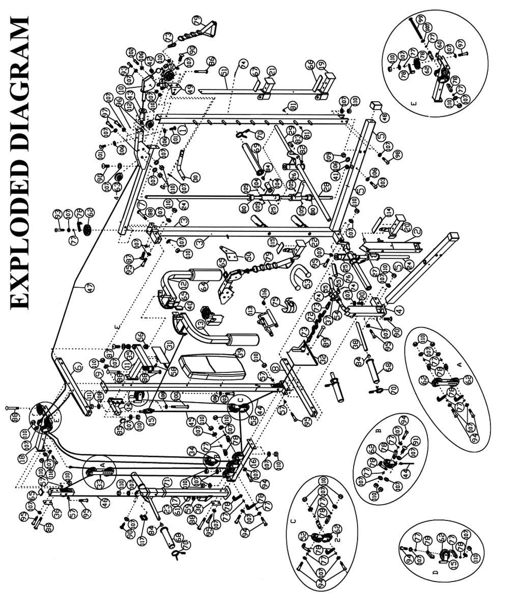
2 TABLE OF CONTENTS BEFORE YOU BEGIN IMPORTANT SAFETY NOTICES... 2 SMITH MACHINE HARDWARE PACK SMITH MACHINE ASSEMBLY INSTRUCTIONS... 6 EXPLODED DIAGRAM. 21 SMITH MACHINE PARTS LIST.. 22 MULTI-PURPOSE BENCH HARDWARE PACK.. 23 MULTI-PURPOSE BENCH ASSEMBLY INSTRUCTIONS EXPLODED DIAGRAM 29 MULTI-PURPOSE BENCH PARTS LIST 30 WEIGHT RESISTANCE CHART 31 WARRANTY ORDERING PARTS BEFORE YOU BEGIN Thank you for selecting the MARCY SM-4008 by IMPEX INC. For your safety and benefit, read this manual carefully before using the machine. As a manufacturer, we are committed to provide you complete customer satisfaction. If you have any questions, or find there are missing or damaged parts, we guarantee you complete satisfaction through direct assistance from our factory. To avoid unnecessary delays, please call our TOLL-FREE customer service number. Our Customer Service Agents will provide immediate assistance to you. Toll-Free Customer Service Number Mon. - Fri. 9 a.m. - 5 p.m. PST info@impex-fitness.com 1
3 IMPORTANT SAFETY NOTICE PRECAUTIONS This exercise machine is built for optimum safety. However, certain precautions apply whenever you operate a piece of exercise equipment. Be sure to read the entire manual before you assemble or operate your machine. In particular, note the following safety precautions: 1. Keep children and pets away from the machine at all times. DO NOT leave children unattended in the same room with the machine. 2. Only one person at a time should use the machine. 3. If the user experiences dizziness, nausea, chest pain, or any other abnormal symptoms, STOP the workout at once. CONSULT A PHYSICIAN IMMEDIATELY. 4. Position the machine on a clear, leveled surface. DO NOT use the machine near water or outdoors. 5. Keep hands away from all moving parts. 6. Always wear appropriate workout clothing when exercising. DO NOT wear robes or other clothing that could become caught in the machine. Running or aerobic shoes are also required when using the machine. 7. Use the machine only for its intended use as described in this manual. DO NOT use attachments not recommended by the manufacturer. 8. Do not place any sharp object around the machine. 9. Disabled person should not use the machine without a qualified person or physician in attendance. 10. Before using the machine to exercise, always do stretching exercises to properly warm up. 11. Never operate the machine if the machine is not functioning properly. 12. A spotter is recommended during exercise. CARE AND MAINTENANCE 1. Lubricate moving parts with WD-40 or light oil periodically. 2. Inspect and tighten all parts before using the machine. 3. The machine can be cleaned using a damp cloth and mild non-abrasive detergent. DO NOT use solvents. 4. Maximum user s weight: 300 lbs. 5. Maximum weights on the Weight Bar: 300 lbs. 6. Maximum weights on Leg Developer: 100 lbs. 7. Maximum weights on Cross-over, Lat Pull: 200 lbs. WARNING: BEFORE BEGINNING ANY EXERCISE PROGRAM, CONSULT YOUR PHYSICIAN. THIS IS ESPECIALLY IMPORTANT FOR INDIVIDUALS OVER THE AGE OF 35 OR PERSONS WITH PRE-EXISTING HEALTH PROBLEMS. READ ALL INSTRUCTIONS BEFORE USING ANY FITNESS EQUIPMENT. IMPEX INC. ASSUMES NO RESPONSIBILITY FOR PERSONAL INJURY OR PROPERTY DAMAGE SUSTAINED BY OR THROUGH THE USE OF THIS PRODUCT. SAVE THESE INSTRUCTIONS. WARNING LABEL PLACEMENT 2
4 The warning labels shown here have been placed on the Rear Base, and Bench Rear Stabilizer. If the labels are missing or illegible, please call customer service at for replacements. Apply the labels in the location shown. 3 SMITH MACHINE HARDWARE PACK
5 NOTE: The following parts are not drawn to scale. Please use your own ruler to measure the size. 4
6 SMITH MACHINE HARDWARE PACK NOTE: The following parts are not drawn to scale. Please use your own ruler to measure the size. 5
7 SMITH MACHINE HARDWARE PACK NOTE: The following parts are not drawn to scale. Please use your own ruler to measure the size. 6
8 SMITH MACHINE HARDWARE PACK 7
9 SMITH MACHINE ASSEMBLY INSTRUCTION Tools Required Assembling the Machine: Two Adjustable Wrenches and Allen Wrenches. NOTE: It is strongly recommended that two or more people assemble this machine to avoid possible injury. STEP 1 (See Diagram 1) A.) Do not tighten Nuts and Bolts until instructed to do so. B.) Insert a Base Frame (#5) into the Rear Left Vertical Frame (#3). Secure it with two M10 x ¾ Allen Bolts (#90) and two Ø ¾ Washers (#107). C.) Repeat B to install the other Base Frame to Rear Right Vertical Frame (#4). D.) Attach Rear Base Frame (#8) to Rear Left and Right Vertical Frame. Secure each end with two M10 x 2 ½ Allen Bolts (#95), four Ø ¾ Washers (#107), and two M10 Aircraft Nuts (#110). E.) Repeat D to connect Rear Top Beam (#6) to Rear Left and Right Vertical Frame. DIAGRAM 1 8
10 STEP 2 (See Diagram 2) A.) Do not tighten the Nuts and Bolts until instructed to do so. B.) Insert a Guide Rod (#24) into the hole on left Base Frame (#5). Secure it with one M8 x 2 3/8 Allen Bolt (#103), two Ø 5/8 Washers (#106), and one M8 Aircraft Nut (#109). Slide the Left Lower Safety Stop Frame (#26) onto the Guide Rod, and then slide one Safety Stop Frame (#25) onto the Guide Rod. C.) Attach the Front Left Vertical Frame (#1) onto the left Base Frame. Secure it with two M10 x 3 1/8 Allen Bolt (#98), four Ø ¾ Washers (#107), and two M10 Aircraft Nuts (#110). D.) Attach one Upper Side Frame (#7) to the Guide Rod, Front Left Vertical Frame, and Rear Left Vertical Frame (#3). E.) Secure the Upper Side Frame to Rear Left Vertical Frame from side with one M10 x 2 ½ Carriage Bolt (#88), one Ø ¾ Washer (#107), and one M10 Aircraft Nut (#110). Secure it from rear with one M10 x 5/8 Allen Bolt (#87) and one Ø ¾ Washer (#107). F.) Secure the Upper Side Frame to the Guide Rod with one M10 x ¾ Allen Bolt (#90), and one Ø ¾ Washer (#107). G.) Secure the Upper Side Frame to the Front Left Vertical Frame with one Left Chin-up Bracket (#49), two M10 x ¾ Allen Bolts (#90) and two Ø ¾ Washers (#107). H.) Repeat B to G above to install the other side. I.) Attach the Chin-up Bar (#30) to the Left and Right Chin-up Bracket (#49 & #50). Secure each end of Chin-up Bar with two M10 x 1 5/8 Carriage Bolts (#86), two Ø ¾ Washers (#107), and two M10 Aircraft Nuts (#110). 9 DIAGRAM 2
11 STEP 3 (See Diagram 3) 10
12 A.) Do not tighten all Nuts and Bolts until instructed to so. B.) Attach the Middle Vertical Frame (#9) under the Rear Top Beam (#6) and onto the Rear Base Frame (#8). C.) Attach the Lower Pulley Frame (#16) to the Middle Vertical Frame from rear. Attach the Foot Plate (#32) to the Middle Vertical Frame from front. Secure them together with two M10 x 3 Carriage Bolts (#89), two Ø ¾ Washers (#107), and two M10 Aircraft Nuts (#110). D.) Attach the Weight Glide Post (#17) to rear of Lower Pulley Frame. Secure the top hole with one 3 1/8 x 1 ¾ Bracket (#36), one M10 x 2 ½ Carriage Bolt (#88), one Ø ¾ Washer (#107), one M10 Aircraft Nut (#110). Secure the lower hole with one M10 x 2 ½ Allen Bolt (#95) and one Ø ¾ Washer (#107). E.) Slide the Sliding Weight Post (#23) to the Weight Glide Post from top. Make sure the triangular bracket on Sliding Weight Post is facing upward. F.) Attach the Rear Upper Frame (#18) to Weight Glide Post. Secure the lower hole with one 3 1/8 x 1 ¾ Bracket (#36), one M10 x 2 ½ Carriage Bolt (#88), one Ø ¾ Washer (#107), one M10 Aircraft Nut (#110). Secure the top hole with one M10 x 2 ½ Allen Bolt (#95) and one Ø ¾ Washer (#107). G.) Attach the Rear Upper Frame to the Rear Top Beam (#6). Secure Rear Upper Frame, Rear Top Beam, and Middle Vertical Frame together with two M10 x 2 ½ Carriage Bolts (#88), two Ø ¾ Washers (#107), and two M10 Aircraft Nuts (#110). H.) Securely tighten all Nuts and Bolts installed in Step-1, Step-2, and Step DIAGRAM 3
13 12 STEP 4 (See Diagram 4) A.) Attach the Butterfly Base (#11) to the front of Middle Vertical Frame (#9). Attach the Butterfly Pulley Bracket (#14) to the Middle Vertical Frame. Secure them together with two
14 M10 x 2 ½ Carriage Bolts (#88), two Ø ¾ Washers (#107), and two M10 Aircraft Nuts (#110). B.) Attach the Butterfly Stopper (#31) to Butterfly Base. Secure it with two M6 x 3/8 Allen Bolts (#58). C.) Attach the Backrest Board (#39) to Middle Vertical Frame. Secure it with two M8 x 2 3/8 Allen Bolts (#103) and two Ø 5/8 Washers (#106). DIAGRAM 4 13 STEP 5 (See Diagram 5) A.) Insert the pivot on the Right Butterfly (#13) into the hole on the Butterfly Base from bottom. Secure it with one Lock Ring (#35), one Ø ¾ Washer (#107), and one M10 x 5/8 Allen Bolt
15 (#87). Push the Butterfly Arm Foam Roll (#64) to Right Butterfly. Repeat same step to install the Left Butterfly (#12). B.) Insert two Swivel Pulley Brackets (#15) into the holes on the Butterfly Pulley Bracket (#14). Secure each Swivel Pulley Bracket with one M12 x 5 Hex Bolt (#100), two Ø 1 Washer (#108), and one M12 Aircraft Nut (#111). Do not over tighten the Nuts. Make sure the Brackets are able to swivel. DIAGRAM 5 CABLE LOOP DIAGRAM 14
16 15 STEP 6 (See Diagram 6 & Cable Loop Diagram) A.) Attach one end of 113 Butterfly Cable (#45) to the clip on Left Butterfly (#12). Draw the Cable to the left Swivel Pulley Bracket (#15).
17 B.) Attach a Pulley (#62) and two Cable Retainers (#78) to the Bracket. C.) Secure them with one M10 x 2 Allen Bolt (#94), two Ø ¾ Washers (#107), and one M10 Aircraft Nut (#110). D.) Draw the Cable around the Pulley then downward. Attach an Angled Floating Pulley Bracket (#52) to the Cable. Repeat Procedure B above to install a Pulley with two Cable Retainers (#78). Draw the Cable around the Pulley then upward to the right Swivel Pulley Bracket. Let the Bracket hanging for now. E.) Repeat Procedure C above to install a Pulley and Cable Retainers to the Bracket. F.) Draw the Cable around the Pulley then clip to the Right Butterfly (#13). STEP 7 (See Diagram 7-1, 7-2 & Upper Cable Loop Diagram) 16
18 A.) Attach the two Cross-over Swivel Pulley Brackets (#10) to left and right Upper Side Frame (#7). Secure each Bracket with four M8 x 3/8 Allen Bolts (#101) and four Ø 5/8 Washers (#106). B.) Remove the U-shaped Connector, Big Washer, and Ball Stopper from one end of 266 Upper Cable (#47). C.) Attach a Pulley (#62) to the left Swivel Bracket and secure it with one M10 x 1 ¾ Allen Bolt (#93), two Ø ¾ Washers (#107), and one M10 Aircraft Nut (#110). D.) Insert the end of Cable through the left Cross-over Swivel Pulley Bracket (#10). Draw the Cable over the Pulley and pull it towards the back of the machine. E.) Attach a Cable Roller (#42) to the left Cross-over Swivel Pulley Bracket (#10). Secure it with one M8 x 1 5/8 Allen Bolt (#102), two Ø 5/8 Washers (#106), and one M8 Aircraft Nut (#109). F.) Attach a Small Pulley (#63) to the opening on the left Upper Side Frame. Secure it with one M10 x 2 ¾ Allen Bolt (#97), two Ø ¾ Washers (#107), and one M10 Aircraft Nut (#110). Draw the Cable around the top of the Small Pulley. G.) Attach another Small Pulley (#63) to the opening next to the Small Pulley installed in F. Repeat F to install the Small Pulley. Draw the Cable under the Small Pulley to an open pulley shaft. H.) Attach a Pulley (#62) to the open pulley shaft. Secure it with one M10 x 1 ¾ Allen Bolt (#93), one Ø ¾ Washer (#107), and one Cable Retainer (#78). I.) Draw the Cable around the Pulley then to an open pulley shaft on Rear Upper Frame (#18). Attach a Pulley to the open shaft. Secure it with one M10 x 2 ¾ Allen Bolt (#97), two Ø ¾ Washers (#107), one Cable Retainer (#78), and one M10 Aircraft Nut (#110). J.) Draw the Cable around the Pulley and to the open bracket on the Rear Upper Frame (#18). Attach a Pulley to the bracket. Secure it with one M10 x 5 Allen Bolt (#99), one Cable Retainer (#78), two Ø ¾ Washers (#107), and one M10 Aircraft Nut (#110). K.) Draw the Cable around the Pulley and downward. Attach a Pulley to a Single Floating Pulley Bracket (#34). Secure the Pulley with one M10 x 2 Allen Bolt (#94), two Ø ¾ Washers (#107), two Cable Retainers (#78), and one M10 Aircraft Nut (#11). Draw the Cable upward to the open bracket one the other side on Rear Upper Frame (#18). Let the Pulley hanging for now. L.) Remove the Nut and Washer installed in J. Attach a Pulley onto the Allen Bolt (#99), then attach a Cable Retainer (#78) to the Pulley, and secure with the removed Washer and Nut. M.) Draw the Cable to open shaft on Rear Upper Frame. Repeat I to install a Pulley. N.) Draw the Cable to an open pulley shaft. Repeat H to install a Pulley. O.) Draw the Cable to the opening on the right Upper Side Frame. Repeat F to install two Small Pulleys #63). P.) Draw the Cable through the right Cross-over Swivel Pulley Bracket. Repeat E to install a Cable Roller (#42). Q.) Re-install the Ball Stopper; Big Washer, and the U-shaped Connector previously removed in A above. Connect a Single Handle (#79) to each end of the Cable with a Hook (#73). Secure each Hook with one M10 x 1 1/8 Allen Bolt (#92) and M10 Aircraft Nut (#110). 17 DIAGRAM 7-1
19 18 DIAGRAM 7-2
20 19 UPPER CABLE (#47) LOOP DIAGRAM
21 20 STEP 8 (See Diagram 8 & Cable Loop Diagram)
22 A.) Attach one end of the 97 Sliding Weight Post Cable (#46) to the Rear Upper Frame (#18). Secure it with one M10 x 2 3/8 Allen Bolt (#118), two Ø ¾ Washers (#107), and one M10 Aircraft Nut (#110). B.) Attach a Pulley (#62) to top holes on the two Double Floating Pulley Brackets (#33). Secure the Pulley with one M10 x 2 Allen Bolt (#94), two Cable Retainers (#78), two Ø ¾ Washers (#107), and one M10 Aircraft Nut (#11). Draw the Cable around the Pulley upward to the opening on the Weight Glide Post (#17). Let the Pulley hanging for now. C.) Attach a Pulley to the opening. Secure it with one M10 x 2 ½ Allen Bolt (#95), two Ø 1 x ½ Pulley Bushings (#57), and one M10 Aircraft Nut (#110). D.) Draw the Cable around the Pulley and then downward to the triangular bracket on Sliding Weight Post (#23). Secure the end of Cable to the bracket with one M10 x ¾ Allen Bolt (#90), two Ø ¾ Washers (#107), and one M10 Aircraft Nut (#110). E.) Attach two Weight Post Olympic Sleeves (#68) onto the Sliding Weight Post. Attach a Spring Clip to each Sleeve. 21
23 22 DIAGRAM 8
24 STEP 9 (See Diagram 9) A.) Draw the 152 Lower Cable (#44) through the opening on Foot Plate (#32) to the opening on bottom of Middle Vertical Frame (#9). B.) Attach a Pulley (#62) to the opening. Secure it with one M10 x 2 ½ Allen Bolt (#95), two Ø 1 x ½ Pulley Bushings (#57), and one M10 Aircraft Nut (#110). C.) Draw the Cable under the Pulley and then upward to the Angled Floating Pulley Bracket (#52) previously installed in Step-6. D.) Attach a Pulley to the Bracket. Secure it with one M10 x 2 Allen Bolt (#94), two Ø ¾ Washers (#107), two Cable Retainers (#78), and one M10 Aircraft Nut (#110). E.) Draw the Cable around the Pulley and then downward to the first open bracket on Lower Pulley Frame (#16). F.) Attach a Pulley to the bracket. Secure it with one M10 x 2 Allen Bolt (#94), two Ø ¾ Washers (#107), one Cable Retainer (#78), and one M10 Aircraft Nut (#110). G.) Draw the Cable under the Pulley through the next open bracket and then to the third open bracket. Repeat F to install a Pulley. H.) Draw the Cable around the Pulley and then upward to the Double Floating Pulley Brackets (#33) previously installed in Step-8. I.) Repeat D to install a Pulley. J.) Draw the Cable around the Pulley then downward to the middle open bracket on Lower Pulley Frame. Repeat D to install a Pulley. K.) Draw the Cable around the Pulley then upward to the Single Floating Pulley Bracket (#34) installed in Step-7. Secure the end of Cable to the Bracket with one M10 x 1 Allen Bolt (#91), two Ø ¾ Washers (#107), and one M10 Aircraft Nut (#110). L.) Move the lower Pulley position on the Double Floating Pulley Brackets will adjust the tension of the whole Cable system. Move up the Pulley will increase the tension. Move down the Pulley will loosen the tension. M.) Attach the Shiver Bar (#54) to the Lower Cable with one 15-link Chain (#72) and two Hooks (#73). Replace the Shiver Bar with Ankle Strap (#75) or Triceps Rope (#53) for various exercises. 23
25 24 DIAGRAM 9
26 STEP 10 (See Diagram 10) A.) NOTE: Help of another person is strongly recommended for this step. Place the Lifting Sleeve (#28) in between the two Safety Stop Frames (#25). Align the holes. Insert the Weight Bar (#29) into the Safety Stop Frame from one end and through the Lifting Sleeve to the other Safety Stop Frame on the opposite side. Secure the Weight Bar to Safety Stop Frame with four M8 x 3/8 Allen Screws (#104) pre-installed on the Safety Stop Frame. B.) Turn the safety catch hook on the Lifting Sleeve forward to secure its position on the selected slots on the Front Left & Right Vertical Frames (#1 & #2). Attach a Weight Bar Olympic Sleeve (#69) to each end of the Weight Bar. Attach a Spring Clip (#70) to the Sleeve. C.) Attach four Weight Posts (#38) to the Rear Left & Right Vertical Frames (#3 &4). Secure each Weight Post with one M10 x ¾ Allen Bolt (#90) and one Ø ¾ Washer (#107). D.) Attach four Weight Post Olympic Sleeves (#68) to the Weight Posts. Attach Spring Clips (#70) to the sleeves. Insert the Left & Right Bar Holders (#21 & 22), the Left & Right Safety Catches (#19 & 20) into the selected holes on the Front Left & Right Vertical Frames. 25
27 26
28 SMITH MACHINE PARTS LIST KEY NO. DESCRIPTION Q ty 1 Front Left Vertical Frame ½ Square End Cap 1 2 Front Right Vertical Frame 1 62 Pulley 20 3 Rear Left Vertical Frame 1 63 Small Pulley 4 4 Rear Right Vertical Frame 1 64 Butterfly Arm Foam Roll 2 5 Base Frame ¾ Square End Cap 5 6 Rear Top Beam 1 66 Left Safety Rubber Bumper 1 7 Upper Side Frame 2 67 Right Holder Rubber Bumper 1 8 Rear Base Frame 1 68 Weight Post Olympic Sleeve 6 9 Middle Vertical Frame 1 69 Weight Bar Olympic Sleeve 2 10 Cross-over Swivel Pulley Bracket 2 70 Spring Clip 8 11 Butterfly Base x 1 ¾ End Cap 2 12 Left Butterfly link Chain 1 13 Right Butterfly 1 73 Hook 4 14 Butterfly Pulley Bracket 1 74 Rivet Swivel Pulley Bracket 2 75 Ankle Strap 1 16 Lower Pulley Frame Grip 2 17 Weight Glide Post 1 77 Cable Retainer Bushing Rear Upper Frame 1 78 Cable Retainer Left Safety Catch 1 79 Single Handle 2 20 Right Safety Catch 1 80 Ø 2 x 1 5/8 Sleeve 8 21 Left Bar Holder 1 81 Ø 5/8 End Cap Right Bar Holder 1 82 Ø ¾ End Cap 2 23 Sliding Weight Post 1 83 Ø ¾ x 2 End Cap 2 24 Guide Rod 2 84 Ø 1 End Cap 8 25 Safety Stop Frame 2 85 Ø 1 ½ End Cap 2 26 Left Lower Safety Stop Frame 1 86 M10 x 1 5/8 Carriage Bolt 4 27 Right Lower Safety Stop Frame 1 87 M10 x 5/8 Allen Bolt 4 28 Lifting Sleeve 1 88 M10 x 2 ½ Carriage Bolt 8 29 Weight Bar 1 89 M10 x 3 Carriage Bolt 2 30 Chin-up Bar 1 90 M10 x ¾ Allen Bolt Butterfly Stopper 1 91 M10 x 1 Allen Bolt 1 32 Foot Plate 1 92 M10 x 1 1/8 Allen Bolt 2 33 Double Floating Pulley Bracket 2 93 M10 x 1 ¾ Allen Bolt 4 34 Single Floating Pulley Bracket 1 94 M10 x 2 Allen Bolt Lock Ring 2 95 M10 x 2 ½ Allen Bolt /8 x 1 ¾ Bracket 2 96 M8 x ¼ Allen Screw 4 37 Rotating Handle 1 97 M10 x 2 ¾ Allen Bolt 6 38 Weight Post 4 98 M10 x 3 1/8 Allen Bolt 4 39 Backrest Board 1 99 M10 x 5 Allen Bolt /8 x 1 ½ Rubber Bumper M12 x 5 Hex Bolt 2 41 Ø 1 ½ x Ø 1 Guide Bushing M8 x 3/8 Allen Bolt 8 42 Cable Roller M8 x 1 5/8 Allen Bolt 2 43 Upper Cable Sleeve M8 x 2 3/8 Allen Bolt Lower Cable M8 x 3/8 Allen Screw Butterfly Cable ST4.0 Philips Screw Rear Vertical Cable Ø 5/8 Washer Upper Cable Ø ¾ Washer ¾ x 2 Base Frame End Cap Ø 1 Washer 4 49 Left Chin-up Bracket M8 Aircraft Nut 4 50 Right Chin-up Bracket M10 Aircraft Nut Front Vertical Frame Panel M12 Aircraft Nut 2 52 Angled Floating Pulley Bracket Plastic Ring 2 53 Triceps Rope V-Bar 1 54 Shiver Bar Right Safety Rubber Bumper 1 55 Rotate Ring Right Holder Rubber Bumper 1 56 Ø 1 ½ x 7/8 Bushing Ø 1 Cone-shaped End Cap 4 57 Ø 1 x ½ Pulley Bushing Square End Cap 1 58 M6 x 3/8 Allen Bolt M10 x 2 3/8 Allen Bolt 1 59 Ø 1 ½ x Ø ½ Spacer /8 x ¾ End Cap 2 27
29 MULTI-PURPOSE BENCH HARDWARE PACK NOTE: The following parts are not drawn to scale. Please use your own ruler to measure the size. 28
30 MULTI-PURPOSE BENCH HARDWARE PACK NOTE: The following parts are not drawn to scale. Please use your own ruler to measure the size. 29
31 MULTI-PURPOSE BENCH ASSEMBLY INSTRUCTION Tools Required for Assembling the Machine: Two Adjustable Wrenches and Allen Wrenches. NOTE: It is strongly recommended that this machine be assembled by two or more people to avoid possible injury. STEP 1 (See Diagram 1) A.) Do not tighten Nuts and Bolts until instructed to do so. B.) Attach the Front Post (#2) to the Front Stabilizer (#9). Secure it with two M10 x 2 ½ Carriage Bolts (#28), two Ø ¾ Washers (#35), and two M10 Aircraft Nuts (#37). C.) Attach the Main Frame (#1) to Front Post. Secure it with two M10 x 2 ¾ Carriage Bolts (#25), two Ø ¾ Washers (#35), and two M10 Aircraft Nut (#37) from side. Secure it with one M10 x 2 ½ Carriage Bolt (#28), one Ø ¾ Washer (#35), and one M10 Aircraft Nut (#37) from top. D.) Attach the other end of Main Frame to the Rear Stabilizer (#3). Secure it with two M10 x 2 ½ Carriage Bolts (#28), two Ø ¾ Washers (#35), and two M10 Aircraft Nuts (#37). E.) Securely tighten all Nuts and Bolts. DIAGRAM 1 30
32 STEP 2 (See Diagram 2) A.) Attach the Incline Support (#8) to the middle side holes on the two Backrest Supports (#7). Secure it with one M10 x 6 7/8 Allen Bolt (#26), two Ø ¾ Washers (#35), and one M10 Aircraft Nut (#37). Do not tighten the Nut and Bolt yet. B.) Attach the bottom side holes on Backrest Supports to the pivot on Main Frame (#1). Secure it with one M10 x 6 7/8 Allen Bolt (#26), two Ø ¾ Washers (#35), and one M10 Aircraft Nut (#37). Securely tighten Nut and Bolt in A & B. C.) Attach two Seat Brackets (#4) to the Main Frame. Secure each Seat Bracket with one M8 x 2 ¾ Allen Bolt (#27), two Ø 5/8 Washers (#36), and one M8 Aircraft Nut (#33). DIAGRAM 2 31
33 STEP 3 (See Diagram 3) A.) Place the Backrest Board (#11) onto the Backrest Supports (#7). Secure it with four M8 x 1 5/8 Allen Bolts (#32) and 5/8 Washers (#36). B.) Place the Seat Pad (#10) onto the two Seat Brackets (#4). Secure it with four M8 x 1 1/8 Allen Bolts (#31) and 5/8 Washers (#36). DIAGRAM 3 32
34 STEP 4 (See Diagram 4) A.) Attach the Leg Developer (#5) to the open bracket on the Front Post (#2). Secure it with one M10 x 3 Allen Bolt (#29), two ¾ Washers (#35), and one M10 Aircraft Nut (#37). B.) Insert the Leg Developer Weight Post (#6) into the hole on Leg Developer. Secure it with one M10 x 2 3/8 Allen Bolt (#30), two Ø ¾ Washers (#35), and one M10 Aircraft Nut (#37). Cover the end of the Post with one Ø 1 x Ø 3/8 Washer (#38) and one Ø 1 1/8 x 1 1/8 Rubber Bumper (#20). C.) Insert three Foam Tubes (#13) halfway through the holes on Front Post and Leg Developer. Push six Foam rolls (#14) onto the Tubes from both ends. Plug six Foam Roll End Caps (#16) into the Ends. D.) Attach an Olympic Sleeve (#15) onto the Leg Developer Weight Post. Attach a Spring Clip (#21) to the Olympic Sleeve. DIAGRAM 4
35 33
36 34 MULTI-PURPOSE BENCH PARTS LIST KEY NO. DESCRIPTION Q ty 1 Main Frame 1 2 Front Post 1 3 Rear Stabilizer 1 4 Seat Bracket 2 5 Leg Developer 1 6 Leg Developer Weight Post 1 7 Backrest Support 2 8 Incline Support 1 9 Front Stabilizer 1 10 Seat Pad 1 11 Backrest Board /8 x 1 1/8 End Cap 4 13 Foam Tube 3 14 Foam Roll 6 15 Olympic Sleeve 1 16 Foam Roll End Cap Square End Cap ¾ Square End Cap Flat End Cap 1 20 Ø 1 1/8 x 1 1/8 Rubber Bumper 1 21 Spring Clip Square End Cap 2 23 Incline Support Grip 1 24 Ø ¾ Bushing 4 25 M10 x 2 ¾ Carriage Bolt 2 26 M10 x 6 7/8 Allen Bolt 2 27 M8 x 2 ¾ Allen Bolt 2 28 M10 x 2 ½ Carriage Bolt 5 29 M10 x 3 Allen Bolt 1 30 M10 x 2 3/8 Allen Bolt 1 31 M8 x 1 1/8 Allen Bolt 4 32 M8 x 1 5/8 Allen Bolt 4 33 M8 Aircraft Nut 2 34 Ø 1 End Cap 1 35 Ø ¾ Washer Ø 5/8 Washer M10 Aircraft Nut Ø 1 x Ø 3/8 Washer 1 6# Allen Wrench (Tool) 1 5# Allen Wrench (Tool) 1 35
37 SM-4008 WEIGHT RESISTANCE CHART Station Low Pulley Butterfly (both arms) Ratio Example 100% 10 lb. plate creates 10 lb. resistance 100% 10 lb. plate creates 5 lb. resistance Left Cross-Over 50% 10 lb. plate creates 5 lb resistance Right Cross-Over 50% 10 lb. plate creates 5 lb resistance *Numbers are approximate. Actual resistance may vary. 36
38 IMPEX INC. LIMITED WARRANTY IMPEX Inc. ("IMPEX ") warrants this product to be free from defects in workmanship and material, under normal use and service conditions, for a period of two years on the Frame from the date of purchase. This warranty extends only to the original purchaser. IMPEX's obligation under this Warranty is limited to replacing or repairing, at IMPEX's option. All returns must be pre-authorized by IMPEX. Pre-authorization may be obtained by calling IMPEX Customer Service Department at All freights on products returned to IMPEX must be prepaid by the customer. This warranty does not extend to any product or damage to a product caused by or attributable to freight damage, abuse, misuse, improper or abnormal usage or repairs not provided by an IMPEX authorized service center or for products used for commercial or rental purposes. No other warranty beyond that specifically set forth above is authorized by IMPEX. IMPEX is not responsible or liable for indirect, special or consequential damages arising out of or in connection with the use or performance of the product or other damages with respect to any economic loss, loss of property, loss of revenues or profits, loss of enjoyments or use, costs of removal, installation or other consequential damages or whatsoever natures. Some states do not allow the exclusion or limitation of incidental or consequential damages. Accordingly, the above limitation may not apply to you. The warranty extended hereunder is in lieu of any and all other warranties and any implied warranties of merchantability or fitness for a particular purpose is limited in its scope and duration to the terms set forth herein. Some states do not allow limitations on how long an implied warranty lasts. Accordingly, the above limitation may not apply to you. This warranty gives you specific legal right. Register on-line at You may also have other rights which vary from state to state. IMPEX INC S. Towne Ave. Pomona, CA ORDERING REPLACEMENT PARTS Replacement parts can be ordered by calling our Customer Service Department toll-free at during our regular business hours: Monday through Friday, 9 am until 5 pm Pacific standard time. info@impex-fitness.com When ordering replacement parts, always give the following information. 1. Model 2. Description of Parts 3. Part Number 4. Date of Purchase 37
MARCY SMITH MACHINE MWB Model MWB Retain This Manual for Reference OWNER'S MANUAL
 NOTE: Please read all instructions carefully before using this product Table of Contents Safety Notice Hardware Identifier Assembly Instruction MARCY SMITH MACHINE MWB-4360 Parts List Warranty Ordering
IRON GRIP STRENGTH SMITH MACHINE
 NOTE: Please read all instructions carefully before using this product Table of Contents Safety Notice Hardware Identifier Assembly Instruction IRON GRIP STRENGTH SMITH MACHINE IGS-4350 Parts List Warranty
DELUXE SMITH MACHINE MSS Model MSS Retain This Manual for Reference
 NOTE: Please read all instructions carefully before using this product Table of Contents Safety Notice DELUXE SMITH MACHINE MSS-1280 Hardware Identifier Assembly Instruction Parts List Warranty Ordering
MARCY DIAMOND ELITE SMITH MACHINE
 NOTE: Please read all instructions carefully before using this product Table of Contents Safety Notice Hardware Identifier Assembly Instruction MARCY DIAMOND ELITE SMITH MACHINE SM-1050 Parts List Warranty
MD-3401 HOME GYM MARCY DIAMOND ELITE. Model MD Retain This Manual for Reference OWNER'S MANUAL
 NOTE: Please read all instructions carefully before using this product Table of Contents Safety Notice Hardware Identifier MARCY DIAMOND ELITE MD-3401 HOME GYM Assembly Instruction Parts List Warranty
DELUXE OLYMPIC BENCH EVE Model EVE Retain This Manual for Reference OWNER'S MANUAL
 NOTE: Please read all instructions carefully before using this product Table of Contents Safety Notice Hardware Identifier Assembly Instruction Parts List Warranty DELUXE OLYMPIC BENCH EVE-1000 Ordering
IVK-2155 HOME GYM. Model IVK Retain This Manual for Reference OWNER'S MANUAL
 NOTE: Please read all instructions carefully before using this product Table of Contents Safety Notice Hardware Identifier IVK-2155 HOME GYM Assembly Instruction Parts List Warranty Ordering Parts Model
MARCY PLATINUM MP 1105 HOME GYM
 NOTE: Please read all instructions carefully before using this product Table of Contents Safety Notice Hardware Pack MARCY PLATINUM MP 1105 HOME GYM Assembly Instruction Parts List Resistance Chart Warranty
MARCY DIAMOND ELITE OLYMPIC BENCH MD-857. Model MD-857. Retain This Manual for Reference OWNER'S MANUAL
 NOTE: Please read all instructions carefully before using this product Table of Contents Safety Notice Hardware Identifier Assembly Instruction MARCY DIAMOND ELITE OLYMPIC BENCH MD-857 Parts List Warranty
EVERLAST SMITH BENCH EVE-890. Model EVE-890. Retain This Manual for Reference OWNER'S MANUAL
 NOTE: Please read all instructions carefully before using this product Table of Contents Safety Notice Hardware Pack Assembly Instruction Parts List Warranty Ordering Parts EVERLAST SMITH BENCH EVE-890
Marcy Diamond Home Gym
 NOTE: Please read all instructions carefully before using this product Table of Contents Safety Notice Hardware Identifier Assembly Instruction Marcy Diamond Home Gym MD-2109 Parts List Resistance Chart
MARCY DIAMOND WEIGHT BENCH MD-844
 NOTE: Please read all instructions carefully before using this product Table of Contents Safety Notice Hardware Pack Assembly Instruction MARCY DIAMOND WEIGHT BENCH MD-844 Exploded Diagram Parts List Warranty
MARCY PLATINUM MP-3500 HOME GYM
 NOTE: Please read all instructions carefully before using this product Table of Contents Safety Notice Hardware Identifier MARCY PLATINUM MP-3500 HOME GYM Assembly Instruction Parts List Warranty Ordering
POWERHOUSE CORNER GYM GS 9
 NOTE: Please read all instructions carefully before using this product Table of Contents Safety Notice Hardware Pack Assembly Instruction Parts List POWERHOUSE CORNER GYM GS 9 Resistance Chart Warranty
MARCY WEIGHT BENCH WM-367. Model WM-367. Retain This Manual for Reference OWNER'S MANUAL
 NOTE: Please read all instructions carefully before using this product Table of Contents Safety Notice Hardware Identifier Assembly Instruction Parts List MARCY WEIGHT BENCH WM-367 Warranty Ordering Parts
WEIGHT BENCH MSS-7500
 NOTE: Please read all instructions carefully before using this product Table of Contents Safety Notice WEIGHT BENCH MSS-7500 Hardware Pack Assembly Instruction Exploded Diagram Parts List Warranty Ordering
MARCY PREMIER HOME GYM
 NOTE: Please read all instructions carefully before using this product Table of Contents Safety Notice Hardware Identifier Assembly Instruction MARCY PREMIER HOME GYM Parts List Resistance Chart Warranty
EVERLAST EVE-840 WEIGHT BENCH
 NOTE: Please read all instructions carefully before using this product Table of Contents Safety Notice Hardware Pack Assembly Instruction EVERLAST EVE-840 WEIGHT BENCH Exploded Diagram Parts List Warranty
BODYFLEX GYM WM Model WM Retain This Manual for Reference OWNER'S MANUAL
 NOTE: Please read all instructions carefully before using this product Table of Contents Safety Notice Hardware Identifier Assembly Instruction BODYFLEX GYM WM 1407 Parts List Resistance Chart Warranty
WMGG-224. GOLD S GYM Multi Purpose Bench. Model WMGG-224. Retain This Manual for Reference OWNER'S MANUAL
 NOTE: Please read all instructions carefully before using this product Table of Content Safety Notice Hardware Identifier Assembly Instruction Parts List Warranty Ordering Parts GOLD S GYM Multi Purpose
MARCY WEIGHT BENCH WM PRO. Model WM PRO. Retain This Manual for Reference OWNER'S MANUAL
 NOTE: Please read all instructions carefully before using this product Table of Contents Safety Notice Hardware Identifier Assembly Instruction MARCY WEIGHT BENCH WM PRO Parts List Warranty Ordering Parts
MARCY WEIGHT BENCH MWB 715B. Model MWB 715B. Retain This Manual for Reference OWNER'S MANUAL
 NOTE: Please read all instructions carefully before using this product Safety Notice Hardware Identifier Assembly Instruction MARCY WEIGHT BENCH MWB 715B Parts List Warranty Ordering Parts Model MWB 715B
APEX JD-3.1 HYPER EXTENSION BENCH
 NOTE: Please read all instructions carefully before using this product Safety Notice Hardware Identifier Assembly Instruction APEX JD-3.1 HYPER EXTENSION BENCH Parts List Warranty Ordering Parts Model
MARCY SMITH MACHINE SM Model SM Retain This Manual for Reference OWNER'S MANUAL
 NOTE: Please read all instructions carefully before using this product Table of Contents Safety Notice Important Assembly Information MARCY SMITH MACHINE SM-4008 Care and Maintenance Parts List Warranty
SMITH MACHINE F-SM. Model F-SM. Retain This Manual for Reference OWNER'S MANUAL
 -- NOTE: Please read all instructions carefully before using this product Table of Contents Safety Notice SMITH MACHINE F-SM Hardware Identifier Assembly Instruction Parts List Model F-SM Retain This Manual
MARCY BODY CYCLE MCPL-105
 NOTE: Please read all instructions carefully before using this product Safety Notice Hardware Identifier MARCY BODY CYCLE MCPL-105 Assembly Instruction Parts List Warranty Ordering Parts Model MCPL 105
MARCY Recumbent Bike PL-960
 NOTE: Please read all instructions carefully before using this product Table of Contents Safety Notice Hardware Identifier MARCY Recumbent Bike PL-960 Assembly Instruction Parts List Computer Warranty
MARCY Elliptical Machine PL-21930
 NOTE: Please read all instructions carefully before using this product Table of Contents Safety Notice Hardware Identifier MARCY Elliptical Machine PL-21930 Assembly Instruction Parts List Computer Warranty
OWNER S MANUAL. Dick s Sporting Goods 345 Court Street Coraopolis, PA Tools Required: Allen Wrench
 Tools Required: Adjustable Wrench Allen Wrench OWNER S MANUAL Retain This Manual For Reference Dick s Sporting Goods 345 Court Street Coraopolis, PA 15108 TABLE OF CONTENTS BEFORE YOU BEGIN..... 1 IMPORTANT
Gym Dandy TEETER TOTTER TT-360. Model TT-360. Retain This Manual for Reference OWNER'S MANUAL
 NOTE: Please read all instructions carefully before using this product Table of Contents Safety Notice Gym Dandy TEETER TOTTER TT-360 Important Assembly Information Care and Maintenance Parts List Warranty
Gym Dandy TEETER TOTTER TT-320. Model TT-320. Retain This Manual for Reference OWNER'S MANUAL
 NOTE: Please read all instructions carefully before using this product Gym Dandy Table of Contents Safety Notice Hardware Pack TEETER TOTTER TT-320 Assembly Instruction Parts List Operation Tips Warranty
GS5 GYM MULTI STATION USER MANUAL
 GS5 GYM MULTI STATION USER MANUAL Product may vary slightly from the item pictured due to model upgrades Read all instructions carefully before using this product. Retain this owner s manual for future
USER'S MANUAL QUESTIONS? TABLE OF CONTENTS CAUTION. Model No. GGSY49230 Serial No. Serial Number Decal (Under Seat)
") Model No. GGSY4920 Serial No. Write the serial number in the space above for reference. USER'S MANUAL Serial Number Decal (Under Seat) QUESTIONS? As a manufacturer, we are committed to providing complete
Model No. GGSY4920 Serial No. Write the serial number in the space above for reference. USER'S MANUAL Serial Number Decal (Under Seat) QUESTIONS? As a manufacturer, we are committed to providing complete
USER'S MANUAL QUESTIONS?
 Model No. WESY19510 Serial No. (Write the serial number in the space above for reference.) USER'S MANUAL Serial Number Decal QUESTIONS? As a manufacturer, we are committed to providing complete customer
QUESTIONS? PATENT PENDING. Model No. WESY85100 Serial No. Write the serial number in the space above for future reference.
 PATENT PENDING Model No. WESY85100 Serial No. Write the serial number in the space above for future reference. Serial Number Decal-- QUESTIONS? As a manufacturer, we are commiffed to providing complete
USER'S MANUAL QUESTIONS? CAUTION. Model No. GGSY Serial No. Write the serial number in the space above for reference.
 Æ Model No. GGSY91.0 Serial No. Write the serial number in the space above for reference. USER'S MANUAL Serial Number Decal QUESTIONS? As a manufacturer, we are committed to providing complete customer
USERÕS MANUAL QUESTIONS?
 Model No. WESY8501 Serial No. Write the serial number in the space above for reference. USERÕS MANUAL Serial Number Decal (Under Seat) QUESTIONS? As a manufacturer, we are committed to providing complete
3 Station Bike Rack Organization Center
 H O L D I N G S, L L C 3 Station Bike Rack Organization Center Model No.: SBR300 This manual is designed to ensure that your new bike rack can be assembled successfully. Most people find that by setting
CS1 CARDIOSTRIDER USER MANUAL
 CS1 CARDIOSTRIDER USER MANUAL 2 TABLE OF CONTENTS BEFORE YOU BEGIN..... 3 IMPORTANT SAFETY NOTICES. 4 WARNING LABEL PLACEMENT.. 5 CONTENTS OF PACKAGING.... 6 HARDWARE PACK 7 ASSEMBLY INSTRUCTIONS 8 18
USERÕS MANUAL QUESTIONS? CAUTION. Model No. PFSY92080 Serial No.
 Model No. PFSY92080 Serial No. The serial number is found in the location shown below. Write the serial number in the space above. USERÕS MANUAL QUESTIONS? Serial Number Decal As a manufacturer, we are
USER'S MANUAL QUESTIONS?
 Model No. WESY86303 Serial No. Write the serial number in the space above for future reference. USER'S MANUAL Visit our website at Serial Number Decal (Under Seat) QUESTIONS? As a manufacturer, we are
FLAT BENCH OWNER S MANUAL QUESTIONS? CAUTION. Visit our website at.
 Model No. GZFW21410 Serial No. Write the serial number in the space above for future reference. Serial Number Decal QUESTIONS? As a manufacturer, we are committed to providing complete customer satisfaction.
Toll-Free Customer Service Number Mon. - Fri. 8 a.m. - 5 p.m. PST
 TABLE OF CONTENTS BEFORE YOU BEGIN.... 2 IMPORTANT SAFETY NOTICES...3 WARNING LABEL PLACEMENT...4 HARDWARE PACK... 5 ASSEMBLY INSTRUCTIONS...6-16 COMPUTER OPERATION GUIDELINE.....17-18 PARTS LIST..........19-21
FLAT BENCH OWNER S MANUAL QUESTIONS? CAUTION. Visit our website at.
 Model No. GZFW20611 Serial No. Write the serial number in the space above for future reference. Serial Number Decal QUESTIONS? As a manufacturer, we are committed to providing complete customer satisfaction.
OWNER S MANUAL F-G3-BASE CAUTION!
 OWNER S MANUAL F-G3-BASE CAUTION! ASSEMBLY MANUAL BEFORE YOU START Remove all parts from the packaging and separate and count each various component to ensure everything has been correctly provided. Follow
User s Manual. Table of Contents CAUTION. Model No. MTSC20000
 Model No. MTSC20000 Table of Contents Important Precautions..........2 Limited Warranty..............2 Before You Begin.............3 How to Set Up and Fold the Scooter...............4 How to Operate the
USER'S MANUAL QUESTIONS?
 Model No. WESY9100 Serial No. Write the serial number in the space above for future reference. USER'S MANUAL Serial Number Decal (Under Seat) QUESTIONS? As a manufacturer, we are committed to providing
USER S MANUAL CAUTION. Visit our website at. new products, prizes, fitness tips, and much more!
 Patent Pending Model No. 831.159730 Serial No. The serial number is found in the location shown below. Write the serial number in the space above. USER S MANUAL Serial Number Decal SEARS, ROEBUCK AND CO.
XM-4424 INTERNATIONAL OLYMPIC BENCH with LEG & PREACHER
 XM-4424 INTERNATIONAL OLYMPIC BENCH with LEG & PREACHER Owner s Manual 8/09 Read all precautions and instructions in this manual before using this equipment. Table of Contents Before You Begin Important
The contents of this package are not suitable for children under 3 years of age.
 FLAT BENCH PRODUCT MANUAL - VERSION 08.17.04 FOR AGES: 13+ WEIGHT LIMIT: 400 Lbs 181 Kgs ADULT(S) NEEDED: TOOLS NEEDED: WARNING/ADVERTENCIA CUSTOMER SERVICE Do not allow more than one person at any time.
XM Owner s Manual. FID BENCH with LEG & PREACHER. Read all precautions and instructions in this manual before using this equipment.
 XM-49 FID BENCH with LEG & PREACHER Owner s Manual 8/09 Read all precautions and instructions in this manual before using this equipment. Table of Contents Important Safety Information Assembly Parts List
USERʼS MANUAL QUESTIONS? CAUTION. Model No. WEBE Serial No.
 www.weiderfitness.com Model No. WEBE0878.1 Serial No. Write the serial number in the space above for future reference. USERʼS MANUAL Serial Number Decal QUESTIONS? If you have questions, or if parts are
Heavy Duty Deluxe Inversion Therapy Table Model ITX9600/IT9600
 Heavy Duty Deluxe Inversion Therapy Table Model ITX9600/IT9600 WARNING: DO NOT USE this equipment without a licensed physician s approval. READ ALL INSTRUCTIONS carefully before using. Misuse of this equipment
Magnetic Elliptical Trainer
 Magnetic Elliptical Trainer ITEM NO.: 400 OWNER S MANUAL IMPORTANT: Read all instructions carefully before using this product. Retain this owner s manual for future reference. The specifications of this
USER S MANUAL CAUTION. Visit our website at. new products, prizes, fitness tips, and much more! Model No Serial No.
 Model No. 831.19832 Serial No. The serial number is found in the location shown below. Write the serial number in the space above. USER S MANUAL Serial Number Decal SEARS, ROEBUCK AND CO. HOFFMAN ESTATES,
ADDAX RX3200. Assembly Instructions & Manual PN: Configuration subject to change
 ADDAX RX3200 Assembly Instructions & Manual PN: 32-1018 Configuration subject to change WARNING DECAL PLACEMENT The decals shown here have been placed on the equipment in indicated locations. If any of
Or call us at: Hours: 8:00 am to 5:00 pm Monday thru Friday
 Bench IMPORTANT: Read all instructions carefully before using this product. Retain this owner s manual for future reference. The specifications of this product may vary from this photo, subject to change
USER'S MANUAL ORDERING REPLACEMENT PARTS QUESTIONS? CAUTION. Visit our website at.
 ORDERING REPLACEMENT PARTS If you encounter any difficulties or problems with this product, contact the ICON Fitness Lifestyle Ltd. office, or write: ICON Fitness Lifestyle Ltd. Greenwich House North Street
ORDERING REPLACEMENT PARTS
 ORDERING REPLACEMENT PARTS If you encounter any difficulties or problems with this product, contact the ICON Fitness Lifestyle Ltd. office, or write: ICON Fitness Lifestyle Ltd. Greenwich House North Street
Be Strong. NS 200X. Assembly Manual. Model: NS 200X. P/N: Rev A (10/04/2006)
") Be Strong. Assembly Manual NS 00X Model: NS 00X P/N: 00-700 Rev A (0/0/00) TABLE OF CONTENTS Before You Assemble... 3 Product Specifications... Product Features... Parts List / Box Contents... 5 Exploded
Be Strong. Assembly Manual NS 00X Model: NS 00X P/N: 00-700 Rev A (0/0/00) TABLE OF CONTENTS Before You Assemble... 3 Product Specifications... Product Features... Parts List / Box Contents... 5 Exploded
ASSEMBLY INSTRUCTIONS. Magne c Resistance Rowing Machine
 ASSEMBLY INSTRUCTIONS Magne c Resistance Rowing Machine Thank you for your purchase of this Harvil Product! We work around the clock and around the globe to ensure that Harvil products maintain the highest
RECUMBENT BIKE IMPORTANT: Read all instructions carefully before using this product. Retain this
 RECUMBENT BIKE IMPORTANT: Read all instructions carefully before using this product. Retain this owner s manual for future reference. The specifications of this product may vary from this photo, subject
HF4145 FOLDING MULTI-POSITION WORKOUT BENCH
 HF4145 FOLDING MULTI-POSITION WORKOUT BENCH Note: Both Serial Number and Model Number are Required when Ordering Parts RECORD SERIAL NUMBER HERE CATALOG NUMBER 0406-001 Customer Service (800) 548-5438
TRIPULL RX2500T. Assembly Instructions & Manual DOC: T. Configuration subject to change
 TRIPULL RX2500T Assembly Instructions & Manual DOC: 32-1005T Configuration subject to change 32-100 5 T R E V. A WARNING DECAL PLACEMENT The decals shown here have been placed on the equipment in indicated
Deluxe Inversion Table Model IT9300/ITX9300
 Deluxe Inversion Table Model IT9300/ITX9300 CAUTION: WARNING: Do not use this inversion table without a physician s approval. Do not let children use the inversion table unsupervised. Read all instructions
ACCORD ELLIPTICAL TRAINER ITEM NO: 93470
 ACCORD ELLIPTICAL TRAINER ITEM NO: 93470 OWNER S MANUAL IMPORTANT: Read all instructions carefully before using this product. Retain this owner s manual for future reference. The specifications of this
XINGGUI Elliptical Cross Trainer
 XINGGUI Elliptical Cross Trainer ITEM NO.: 93040 OWNER S MANUAL IMPORTANT: Read all instructions carefully before using this product. Retain this owner s manual for future reference. The specifications
Magician Comfy. Owner s Manual
 Magician Comfy Owner s Manual Table Of Contents Introduction...................................... 2 Safety Precautions................................ 3 Assembly........................................4-9
Inversion Table OWNER S MANUAL. Item
 Inversion Table OWNER S MANUAL Item TABLE OF SERVICE ------------------------------------------------------------------------- 2 IMPORTANT LABELS --------------------------------------------------------
Operating Instructions & Parts Manual. Fuel Tank Adapter
 Operating Instructions & Parts Manual Fuel Tank Adapter Model Number 40080 Capacity 80 lb.! This is the safety alert symbol. It is used to alert you to potential personal injury hazards. Obey all safety
OX2 RX2000. Assembly Instructions & Manual PN: Configuration subject to change
 OX2 RX2000 Assembly Instructions & Manual PN: 32-1013 Configuration subject to change WARNING DECAL PLACEMENT The decals shown here have been placed on the equipment in indicated locations. If any of the
HEALTH IN MOTION, LLC. 255 AIRPORT CIRCLE, SUITE 101 CORONA, CA
 TABLE OF CONTENTS BEFORE YOU BEGIN 1 IMPORTANT SAFETY NOTICE 2 CONTENTS OF PACKAGING 3 LABEL PLACEMENT 4 HARDWARE PACK 5 ASSEMBLY INSTRUCTIONS 6-15 PRODUCT FEATURES 16-17 COMPUTER OPERATION GUIDELINE 18-22
OWNER S MANUAL QUESTIONS? CAUTION. Model No. F811.0 Serial No. Write the serial number in the space above for reference. Serial Number Decal
 Model No. F811.0 Serial No. Write the serial number in the space above for reference. OWNER S MANUAL Serial Number Decal QUESTIONS? If you have questions, or if parts are damaged or missing, please see
OWNERS MANUAL HF4263
 OWNERS MANUAL HF4263 ADJUSTABLE AB / BACK HYPER BENCH Note: Both Serial Number and Model Number are Required when Ordering Parts RECORD SERIAL NUMBER HERE CATALOG NUMBER 0805-000 Customer Service (800)
OWNERS MANUAL HF4985. Note: Both Serial Number and Model Number are Required when Ordering Parts (800) (619) CATALOG NUMBER
 (619) CATALOG NUMBER") OWNERS MANUAL HF4985 Note: Both Serial Number and Model Number are Required when Ordering Parts RECORD SERIAL NUMBER HERE Customer Service (800) 548-5438 (619) 578-7676 CATALOG NUMBER Fax 1205-000 (619)
OWNERS MANUAL HF4985 Note: Both Serial Number and Model Number are Required when Ordering Parts RECORD SERIAL NUMBER HERE Customer Service (800) 548-5438 (619) 578-7676 CATALOG NUMBER Fax 1205-000 (619)
48 SUPER JUMPER KIDS TRAMPOLINE
 48 SUPER JUMPER KIDS TRAMPOLINE PRODUCT MANUAL - VERSION 01.18.07 FOR AGES: WEIGHT LIMIT: 100 Lbs 45 Kgs TO BUILD: 3-10 1 X TOOLS NEEDED: CUSTOMER SERVICE GQBrands.com CustomerService@GQBrands.com 1-866-498-5269
TABLE OF CONTENTS. Important Safety Information 3. Parts List 4
 1 TABLE OF CONTENTS Important Safety Information 3 Parts List 4 Assembling THERACK 5 7 How To Unfold THERACK 8 How To Fold THERACK 9 THERACK Levels 10 Warranty 11 2 IMPORTANT SAFETY INFORMATION IMPORTANT:
OnBoard Drum Major Podium
 Assembly and Owner s Manual OnBoard Drum Major Podium CONTENTS CONTENTS................................................................................. 1 SAFETY...................................................................................
Owner s Manual. Upper Body Unit. Serial Number Here. Date of Purchase New Hope Road, Raleigh, NC Fusion -
 Revision 3 April 2015 Upper Body Unit Owner s Manual Serial Number Here Date of Purchase www.batcafitness.com 1207 New Hope Road, Raleigh, NC - 919.255.1233 Fusion - www.batcafitness.com 4 Upper Body Station
OWNERS MANUAL HF4261
 OWNERS MANUAL HF4261 ADJUSTABLE AB BENCH Note: Both Serial Number and Model Number are Required when Ordering Parts RECORD SERIAL NUMBER HERE CATALOG NUMBER 0905-000 Customer Service (800) 548-5438 (858)
Owner s Manual. Upper Body Unit. Serial Number Here. Date of Purchase New Hope Road, Raleigh, NC Fusion -
 Revision 1 March 2012 Upper Body Unit Owner s Manual Serial Number Here Date of Purchase www.batcafitness.com 1207 New Hope Road, Raleigh, NC - 919.255.1233 Fusion - www.batcafitness.com 4 Upper Body Station
USER MANUAL. Homegym IN 133 EASY
 USER MANUAL Homegym IN 133 EASY Safety please be sure to consult with your doctor. Frequent strenuous exercise should be approved your doctor and proper use of your multi gym product is essential. Please
WARNING Read these materials prior to assembling and using the trampoline and Trampoline Enclosure
 & Rectangular PowerBounce User s Manual Assembly, Installation, Care, Maintenance, and Use Instructions WARNING Read these materials prior to assembling and using the trampoline and Trampoline Enclosure
ATD Gallon Pressurized Oil Drain Owner s Manual
 ATD-5203 30 Gallon Pressurized Oil Drain Owner s Manual TECHNICAL SPECIFICATIONS Model: ATD-5203 Capacity: 30 Gallon Drain Funnel Working Height: 47.25 to 70.5 Drain Funnel Diameter: 15.75 Plastic Tray:
Installation Instructions
 Installation Instructions ELECTRIC CONVERSION KIT 3 ALUMINUM ROLL TUBE IMPORTANT: This Electric Conversion Kit has been designed for systems with a 3 aluminum roll tube. It is assumed that the tarping
1500- LB. HIGH POSITION HOIST STAND OWNER S MANUAL
 1500- LB. HIGH POSITION HOIST STAND OWNER S MANUAL WARNING: Read carefully and understand all ASSEMBLY AND OPERATION INSTRUCTIONS before operating. Failure to follow the safety rules and other basic safety
ASSEMBLY / OPERATION INSTRUCTIONS. Low Profile Motorcycle Dolly
 ASSEMBLY / OPERATION INSTRUCTIONS 1,500LB CAPACITY Low Profile Motorcycle Dolly Model: 03-CG1500-01(B1) WARNING BEFORE USE PLEASE READ ALL WARNINGS AND INSTRUCTIONS TO PREVENT SERIOUS INJURY Drop-Tail
Owner s Manual
 Owner s Manual 800-342-8968 www.easystand.com Table Of Contents Introduction...................................... 2 Safety Precautions................................ 3 Assembly........................................4-7
INSTALLATION INSTRUCTIONS
 INSTALLATION INSTRUCTIONS Thank you for purchasing ROXTERTM Hitch Mounted Mud Flaps. Agri-Cover, Inc. proudly manufactured these mud flaps using superior quality materials and workmanship. With proper
KIDS ROCKER SEESAW MODEL# 9306RS PRODUCT MANUAL - VERSION
 KIDS ROCKER SEESAW PRODUCT MANUAL - VERSION 01.18.06 FOR AGES: WEIGHT LIMIT: 150 Lbs 68 Kgs TO BUILD: 3-7 1 X TOOLS NEEDED: WARNING/ADVERTENCIA Please read all the instructions before using this product.
ASSEMBLY MANUAL 9GU - COMMERCIAL UPRIGHT BIKE
 ASSEMBLY MANUAL 9GU - COMMERCIAL UPRIGHT BIKE IMPORTANT SAFETY INSTRUCTIONS Read this Owner s Manual and follow it s instructions carefully before using the machine. Make sure that it is properly assembled
PT1 Power Trainer ASSEMBLY & OPERATION MANUAL RECORD SERIAL NUMBER HERE
 PT1 Power Trainer ASSEMBLY & OPERATION MANUAL RECORD SERIAL NUMBER HERE www.inspirefitness.net by Health In Motion LLC Dec. 2010 TABLE OF CONTENTS Section Description.. Page Instructions.. 1 Tools Required
Assembly Instructions
 Assembly Instructions Aluminum Padded Sling Chaise Lounge Questions, problems, or missing parts? Before returning to the store, call Customer Service. -866-988-3300 8 a.m. -5 p.m., PST Monday - Friday
Deluxe Folding Bike XRB271 / XRB261. * This item is for consumer use only and it is not meant for commercial use. OWNER S MANUAL
 Deluxe Folding Bike XRB271 / XRB261 * This item is for consumer use only and it is not meant for commercial use. OWNER S MANUAL General Information Safety Before you undertake any exercise program, please
Pontoon and Tri-Toon Bunk Assembly Instructions
 Pontoon and Tri-Toon Bunk Assembly Instructions INTRODUCTION The Starr line of Boat Lift Canopy Frames by Great Lakes Entry Systems has been engineered to provide the best possible performance, long term
USER MANUAL ASSEMBLY, MAINTENANCE, &
 ASSEMBLY, MAINTENANCE, & USER MANUAL MODEL #SWBB00 WARNING Read all precautions and instructions in this manual before using this equipment. Save this manual for future reference. Skywalker Holdings LLC
Owner s Manual. 4 Functional Trainer. Serial Number Here. Date of Purchase
 Revision 2 June 2014 Functional Trainer Owner s Manual Serial Number Here Date of Purchase www.batcafitness.com 1207 New Hope Road, Raleigh, NC - 919.255.1233 Fusion - www.batcafitness.com 4 Functional
Installation Instructions Soft Top Replacement Hardware, Wrangler
 Installation Instructions Soft Top Replacement Hardware, 87-95 Wrangler IMPORTANT NOTICE: Carefully read instructions before attempting to install this product. Rampage is in no way responsible for any
BRF 700 Fan Bike. * This item is for consumer use only and it is not meant for commercial use.
 BRF 700 Fan Bike * This item is for consumer use only and it is not meant for commercial use. OWNER S MANUAL This page intentionally left blank General Information Safety Before you undertake any exercise
Manual Treadmill with Pulse
 Manual Treadmill with Pulse V1.0-082715 OWNER S MANUAL Item #1005 TABLE OF CONTENTS SERVICE ------------------------------------------------------------------------ 2 IMPORTANT LABELS --------------------------------------------------------