Cargo Securing Guidelines for Road Transport U.S. Steel Košice, s.r.o.
|
|
|
- Junior Lee
- 5 years ago
- Views:
Transcription
1 Cargo Securing Guidelines for Road Transport U.S. Steel Košice, s.r.o. Guidelines for loading staff and drivers Ing. Juraj Jagelčák, PhD. prof. Ing. Jozef Gnap, PhD. Department of Road and Urban Transport University of Zilina July 2012
2 LIST OF CONTENTS 1 GENERAL GUIDELINES FOR LOADING AND SECURING A CARGO Application of the guidelines Vehicle requirements Lashing straps Anti-slip mats Basic rules for cargo securing in USSK PRODUCT STRUCTURE OF USSK IN REGARD TO THESE GUIDILINES SHEETS IN BUNDLES Loading and securing Sheets bundles securing examples TIN PLATES ON WOODEN OR STEEL PALLETS WINDING AXIS VERTICAL UP TO 12 TONNES Loading Cargo securing examples of cold-rolled tin plates on pallets COILS AND COIL-STRIPS ON WOODEN BATTENS WINDING AXIS VERTICAL (EYE-TO-THE-SKY) Loading Cargo securing Securing examples of coils with winding vertical on wooden battens up to 10 tonnes Unstable coils COILS AND COIL-STRIPS ON WOODEN SLEDGES WITH WINDING AXIS PARALEL TO LONGITUDINAL VEHICLE AXIS UP TO 10 TONNES Loading Cargo securing Securing of coils in wooden sledges winding axis horizontal up to 10 tonnes Unstable coils COILS LOADED IN A COIL-WELL WITH WINDING AXIS PARALEL TO LONGITUDINAL VEHICLE AXIS UP TO 20 TONNES Loading and cargo securing Securing examples of coils in a coil-well Securing of unstable coils blocked by stanchions forwards against tilting rearwards SPIRAL-WELDED STEEL PIPES Loading Cargo securing Selected loading combinations of pipes in USSK (mass is valid for 12 meters pipes) Securing examples of selected loading combinations of pipes
 and pipes from")


 according instructions in way-bills!")

3 1 GENERAL GUIDELINES FOR LOADING AND SECURING A CARGO 1.1 APPLICATION OF THE GUIDELINES These guidelines apply for all road vehicles carrying the steel sheets (bundles, coils, coil strips) and pipes from U.S. Steel Kosice s.r.o. (USSK) to our customers. Given the diversity of cargo carried, guidelines contain cargo securing principles for individual types of load. Guidelines are based on current cargo securing standards and measured results of selected cargoes. Cargo securing instructions are based on the estimated parameters as e.g. cargo weight, dimensions, friction factors, lashing angles, tensioning forces, lashing forces, use of anti-slip mats and the like. These guidelines are minimum requirements to protect our goods. They do not indemnify the carrier from his responsibility to take additional measures as he may deem necessary mainly in case of difficult loadings, difficult weather conditions (ice, snow, icing...) DRIVER BEHAVIOR Drivers must follow work safety regulations in USSK. Drivers must wear personal protective equipment (PPE) according instructions in way-bills! The driver is obliged to wear PPE during the whole loading or unloading of the vehicle. Vehicle must be weighted at the entrance gate into USSK! Furnishing of the vehicle on loading site, tarpaulins removal, manipulation with sideboards and cargo securing is performed by the driver. Driver checks stowage of load on a loading platform during the whole loading. 1.2 VEHICLE REQUIREMENTS HEADBOARD The vehicle must be fitted with a headboard between the cabin and the loading platform to protect the vehicle personnel in case of load shifts forwards. Headboard has to be functional without cracks in bearing weld seams. Vehicle without lashing points with damaged headboard! 2


4 We recommend vehicle superstructures certified according to the standard EN Code XL for our goods! Vehicle body marking according to EN LOADING PLATFORM The surface of the loading platform should be even and closed (no missing or broken boards). The cargo should not become wet from below. In case of semi-trailer with a coil-well this must be without any missing or broken coil-well covers. The loading platform should be dry and clean before loading LASHING POINTS Loading platform must have anti-skid floor (not metal floor)! Lashing points should be an integral part of the vehicle construction. Usual semi-trailer must be equipped by minimum 12 pairs of lashing points (24 lashing points) with minimum safe working load of We recommend vehicles with lashing rails for our goods or at least 17 pairs of lashing points. 3


5 1.2.4 SEMI-TRAILERS FITTED WITH A COIL-WELL - Minimum angle of slopes shall be Minimum span between supporting surfaces shall be 0,6 D. - Vehicle must be equipped with stanchions plugged into the cases in a coil-well. Coil must be placed against the stanchions. If coil might be damaged by stanchions use protective material. - In case of metal surface of the coil-well the use of anti-slip mats between the coil and the coil-well is obligatory. - Coil might not be laying on the bottom of the coil-well (minimum clearance 20 mm), always must be laying on coil-well slopes. D coil diameter Depth of the coilmin. 0,6 D 35 Minimum clearance 20mm Width of the coil-well 4


6 5

 against sharp edges.")
7 1.3 LASHING STRAPS Vehicle must be equipped with sufficient number of lashing straps! - Minimum 16 pcs for tractor + semi-trailer and vehicle + trailer combinations with a lashing capacity LC = min Particular types of loading may require more straps. - Minimum 8 pcs for vehicle with a payload over 3,5 tonnes to 12 tonnes with a lashing capacity LC = min. 2000, Particular types of loading may require more straps. - Minimum 4 pcs for a vehicle with a payload not more than 3,5 tonnes with a lashing capacity LC = min. 2000, Particular types of loading may require more straps. - Sufficient number of straps protective equipment (corner protectors, sleeves etc.) against sharp edges. - Lashing straps must be certified according to the standard EN Lashing capacity LC = min. 2000! (2500 recommended) and standard tension force STF = min length of lashing straps must be sufficient for applied lashing method - lashing straps must be visually inspected before each use - lashing straps end fittings must be suitable for lashing points on a vehicle We recommend long handle ratchets STF = 500 for our goods! CONDITIONS OF USAGE - Use only damage-free lashing straps with readable identification tag indicating lashing capacity (LC) and standard tension force (STF). - Identification tags should be protected from sharp edges or even the load itself if possible. - Lashing straps mustn t be knotted. - Lashing straps mustn t lead over sharp edges or rough surfaces without equivalent protection. - Lashing straps must never be used for lifting loads or for any other purpose for which they are not intended. - Lashing hooks must not be loaded at their tips unless the hooks are specially designed for this purpose. - To avoid stress on tensioning devices and fasteners, do not lay them across edges, otherwise they may fracture. - Lashing straps must not be used again after the fracture, deformation of connective elements or tensioning elements. - Driver is obligated to check the tension in lashings short after the start and, if he is aware of loosening, also during the carriage in necessary periods. - Change of temperature during the carriage can affect the tension forces in lashing straps therefore check the tension after entry to warm area. - Driver is responsible for functional lashing straps. 6


8 1.4 ANTI-SLIP MATS - material rubber granulate - minimum friction factor 0,5 - minimum thickness 10 mm 1.5 BASIC RULES FOR CARGO SECURING IN USSK 1. Never carry the unsecured load even for short distances! 24 tones of coil strips carried according driver for short distance unsecured! Semi-trailer was not equipped with lashing points!!! 2. Cargo must be always secured forwards! Bales of sheets of 12 tones unsecured forwards! 7
 wood/plywood floor always use anti-slip mats. 4.")

9 3. Never place steel products on metal floor this is also valid for coil-well! By contact surface steel metal platform always use anti-slip mats. By contact surface steel (wedge bed, steel pallet) wood/plywood floor always use anti-slip mats. 4. Use lashing straps of minimum lashing capacity LC = 2000, standard tension force STF = 500 (long ratchets) and sufficient number! 5. For cargo securing use lashing points designed for this purpose. If the load displacement doesn t allow doing that, lash the lashings to the vehicle or superstructure chassis! But watch out of sharp edges! Control officers in Germany do not allow lashing to vehicle/superstructure chassis. They can define the vehicle as inappropriate for carriage. They can order to load the cargo on another vehicle. We recommend vehicles with lashing rails or at least 17 pairs of lashing points for our goods. 8


10 6. It is necessary for vehicles carrying steel products to be equipped with lashing points of sufficient strength and number! Usual semi-trailer must be equipped with 12 pairs of lashing points with minimum safe working load of By vehicles without any lashing points it is not possible to secure the load safely and efficient! We recommend vehicles with lashing rails or at least 17 pairs of lashing points for our goods. 7. Be aware of sharp edges, loose steel products have sharp edges and can cut the lashing straps, use protective material (corner protectors, sleeves...)! 9


11 8. Never load the lashing point in the same direction! In one lashing point can be maximum 3 lashing straps but each in different direction of loading that is e.g. during braking is force transferred to lashing point by only one lashing straps. We recommend vehicles with lashing rails for our goods. 9. Anti-slip mats (ASM) decrease the number of additional securing equipment! Always use ASM correctly. When using ASM cargo must be placed in a way that there are no contact points with loading platform and the whole cargo mass is transferred to loading platform through ASM. 10

12 2 PRODUCT STRUCTURE OF USSK IN REGARD TO THESE GUIDILINES SHEETS PRODUCTS PIPE S bundles small bundles OV bundles DZ Tva, DZ Sva, DZ ZU, OV wood and steel pallets OV winding axis vertical coils DZ Tva, DZ Sva, DZ ZU coils-strips wooden supports winding axis horizontail/vertical in coil-well winding axis horizontal LASHING ANGLES x y...angle between lashing axis and horizontal plane x...angle in horizontal plane between vertical projection of lashing axis to horizontal plane and vehicle longitudinal axis y... angle in horizontal plane between vertical projection of lashing axis to horizontal plane and vehicle transverse axis 11
 to place the bundles in units and secure the whole unit forwards, rearwards and sideways.")

13 3 SHEETS IN BUNDLES 3.1 LOADING AND SECURING Placing of bundles in longitudinal direction without gaps, blocking to the headboard, if necessary (e.g. load distribution) use of e.g. pallets to fill the distance between headboard and the first bundle or spring lashing. It is reasonable (e.g. distance between lashing points or load displacement) to place the bundles in units and secure the whole unit forwards, rearwards and sideways. In case of gaps between units each unit must be secured individually forwards (practise: German authorities ordered to fill each gap!). If the bundles are loaded in layers and some layer is not secured forwards it must be secured by spring lashing. Never carry the cargo unsecured forwards! When loading bundles on semi-trailer with a coil well always consider possible blocking by the headboard and stanchions forwards and if it is not possible use lashing against forward movement! The same is valid if empty pallets are available on loading platform or in pallet basket to fill up gaps in forward direction. SHEETS BUNDLES UNSECURED FORWARDS PENETRATED HEADBOARD DURING HEAVY BREAKING! Top-over lashing never secures the load forwards by reasonable number of lashings! 12


14 3.1.1 SPRING LASHING FOR SECURING FORWARDS/REARWARDS VARIANT SL1 Bundles in several layers to prevent longitudinal movement FIX HOOKS MORE FURTHER! Variant SL1 Mass of secured cargo Securing forwards NO KNOTS! Securing rearwards SHARP EDGES! No. of lashing straps (2 lashing lines) Banded greased or oiled sheets Packed sheets Banded sheets without surface coating-clean, sheet/wood, wood/plywood Banded greased or oiled sheets Packed sheets Banded sheets without surface coating-clean, sheet/wood, wood/plywood 2,6 t 3,3 t 5,3 t 4,6 t 6,6 t 21,3 t 5,3 t 6,6 t 10,7 t 9,3 t 13,2 t 27 t 3 7,9 t 9,9 t 16 t 13,9 t 19,8 t 4 10,6 t 13,2 t 21,3 t 18,5 t 26,5 t 5 13,2 16,5 26,7 23,2 t 6 15,9 19,8 For other lashing angles see tables in TAB 1 TAB 3 TAB 5 TAB 2 TAB 4 TAB 6 annex Friction factor f = 0,1 f = 0,2 f = 0,4 f = 0,1 f = 0,2 f = 0,4 Lashing angles r = max. 50, x r = max. 45 l = max. 20, x l = max. 45 r...right line, l...left line of strap r = max. 50, x,y r = max. 45 l = max. 20, x,y l = max. 45 r...right line, l...left line of strap In case of bundles in more layers consider lashing of layers separately (not only the whole cargo) or lashing in combination with wooden blocks. 13

15 VARIANT SL2 One or two bundles in one layer in combination with top-over lashing to prevent spring lashing to slip off SPRING LASHING LEADS OVER TOP-OVER LASHING WITH SUITABLE ANGLE TO PREVENT FROM SLIPPING! Variant SL2 Mass of secured cargo Securing forwards Securing rearwards No. of lashing straps (2 lashing lines) Banded greased or oiled sheets Packed sheets Banded sheets without surface coating-clean, sheet/wood, wood/plywood Banded greased or oiled sheets Packed sheets Banded sheets without surface coating-clean, sheet/wood, wood/plywood 3,5 t 4,1 t 6,1 t 6,1 t 8,2 t 24,6 7 t 8,2 t 12,3 t 12,3 t 16,4 t 27 t 3 10,5 t 12,3 t 18,4 t 18,4 t 24,6 t 4 14 t 16,4 t 24,6 t 24,6 t 27 t 5 17,5 t 20,5 t 27 t 27 t 6 21 t 24,6 t For other lashing angles see tables in TAB 8 TAB 10 TAB 12 TAB 9 TAB 11 TAB 13 annex Friction factor f = 0,1 f = 0,2 f = 0,4 f = 0,1 f = 0,2 f = 0,4 Lashing angles r = max. 20, x r = max. 30 l = max. 20, x l = max. 30 r...right line, l...left line of strap 14 r = max. 20, x,y r = max. 30 l = max. 20, x,y l = max. 30 r...right line, l...left line of strap
 without possibility of movement of individual sheets from bundles.")
16 3.1.2 TOP-OVER LASHING FOR SECURING SIDEWAYS/REARWARDS Use for short bundles 2 3 m, tin plates (about 1 m x 1 m) already secured forwards! Use mainly for compact packaging (sufficiently packed) without possibility of movement of individual sheets from bundles. Mass of secured cargo by 1 top-over lashing against sliding sideways/rearwards Ratchet type Standard tension force in lashing strap STF Banded greased or oiled sheets Packed sheets Banded sheets without surface coating-clean, sheet/wood, wood/plywood Rubber anti-slip mats between cargo and platform or between cargo layers For other lashing angles see tables in annex Friction factor kg 1572 kg kg 1834 kg BLOCKING, SPRING OR LOOP LASHING 349 kg 436 kg 2096 kg 2621 kg kg 3931 kg kg 5242 kg Lashing angles = TAB kg = 0,1 = 0,2 = 0,4 > 0,5 15


17 LOOP LASHING FOR CARGO SECURING SIDEWAYS Loop lashing 2 variants use for long bundles over 3 m in length and also for shorter bundles where great number of top-over lashings is necessary. x x x Cargo mass secured by pairs of loop lashing sideways for two variants of loop lashing Variant LL1 LL1 Variant LL2 LL2 Number of pairs of lashing straps Banded greased or oiled sheets Packed sheets Banded sheets without surface coating-clean, sheet/wood, wood/plywood Banded greased or oiled sheets Packed sheets Banded sheets without surface coating-clean, sheet/wood, wood/plywood 1 3,8 t 5,7 t 20,2 2 t 3 t 10,6 t 2 7,7 t 11,5 t 27 t 4 t 6 t 21,1 t 3 11,5 t 17,2 t 6,1 t 9 t 27 t 4 15,3 t 22,9 t 8,1, t 12,1 t 5 19,2 t 28,6 t 10,1 t 15,1 t 6 23 t 12,1 t 18,1 t 7 26,8 t 14,1 t 21,1 t 8 16,2 t 24,1 t For other lashing angles see tables in annex TAB2 TAB4 TAB6 TAB 2 TAB4 TAB6 Friction factor f = 0,1 f = 0,2 f = 0,4 f = 0,1 f = 0,2 f = 0,4 Lashing angles 1=max.90, 2=max.20, y= top line over the cargo 2...bottom line under the cargo 1=max.90, 2=max.20, y=0, x= top line over the cargo 2...bottom line under the cargo 16

18 3.2 SHEETS BUNDLES SECURING EXAMPLES SECURING EXAMPLES OF COLD-ROLLED SHEETS IN SMALL BUNDLES 17
19 1. Securing of group of bundles forwards by filling of empty space by pallets and top-over lashing sideways/ rearwards. 2. Securing of group of bundles forwards by stanchions and top-over lashing sideways/rearwards. 3. Securing of group of bundles forwards by 1 spring lashing (SL2 red strap) and top-over lashing sideways/rearwards (red strap over yellow strap against slipping). 4. Securing of group of bundles forwards by 1 spring lashing (SL2) and top-over lashing sideways/rearwards alternative solution to prevent spring lashing slipping. 5. Possible use of anti-slip mats for heavier cargo for all cargo loadings or in case of low top-over lashing angles 1 top-over lashing for 4 tonnes of cargo in case of use of anti-slip mats and compact packaging. 6. Securing of group of bundles forwards by 2 spring lashings (SL1-blue and red strap) and top-over lashing sideways/rearwards. For heavier cargo consider use of anti-slip mats. 7. Securing of group of bundles forwards by filling of empty space by pallets and top-over lashing sideways/rearwards. 8. In case of doubts about the strength of the stanchions strengthen the stanchions by 1 / 2 spring lashings. 9. A combination of spring lashings (SL2 - red and green strap) for securing of group of bundles forwards/rearwards and top-over lashing (yellow straps) sideways
 and loop lashing (LL2-green and blue straps) of both layers sideways (in case of")
20 SECURING EXAMPLES OF HOT/COLD-ROLLED SHEETS IN BUNDLES 1. Cargo blocked by the headboard of sufficient strength (EN XL), top-over lashing sideways/rearwards. 2. Securing of incomplete upper layer against movement forwards/rearwards by 1 spring lashing (Variant SL2 red straps) and loop lashing (LL2-green and blue straps) of both layers sideways (in case of low friction between layers). 3. Cargo section blocked by stanchions forwards and top-over lashing sideways/rearwards. 4. Cargo section secured by 2 spring lashings (SL2-red and blue strap) in combination with a pallet (two wooden blocks 100x100 mm placed in a pallet vertically for more cargo layers), and top-over lashing sideways/rearwards. 5. Cargo section secured by 2 crossed spring lashings (SL1-red and blue strap), and top-over lashing sideways/rearwards. 19

21 1. Cargo blocked by headboard of sufficient strength (EN XL), top-over lashing sideways/rearwards. 3. Cargo section blocked by stanchions forwards, and top-over lashing sideways/rearwards. In case of doubts about the strength of the stanchions strengthen the stanchions by 1 or 2 spring lashings SL2. 6. Filling of empty space by pallets as blocking aid forwards and securing of pallets by top-over lashing sideways/rearwards, headboard of sufficient strength (EN XL). 7. Smaller bundles than half of the platform width can be stowed next to each other for better top-over lashing angle. 20
. 10.")
22 8. Cargo securing sideways by loop lashings (LL1 resp. LL2 light blue and green straps). 9. Filling of empty space by pallets as blocking aid forwards and securing of pallets by top-over lashing sideways/rearwards, headboard of sufficient strength (EN XL). 10. Cargo securing rearwards by 2 crossed spring lashings (SL1 red and dark-blue strap). 11. Cargo blocked forwards by stanchions. In case of doubts about the strength of the stanchions strengthen the stanchions by 1 or 2 spring lashings SL2. 21
. 13.")
23 12. Cargo securing of unblocked cargo forwards by spring lashings in combination with a pallet and wooden blocks 100 x 100 mm (SL2). 13. Cargo securing of unblocked cargo forwards by spring lashings (SL1). 22


24 4 TIN PLATES ON WOODEN OR STEEL PALLETS WINDING AXIS VERTICAL UP TO 12 TONNES 4.1 LOADING Place coils on a loading platform in a way to achieve correct load distribution. In case of semi-trailer with a coil-well consider use of stanchions to block the cargo forwards especially coils on steel pallets. Always use anti-slip mats with minimum thickness of 10 mm under the pallets. WRONG SECURING OF COIL, COIL NOT SECURED FORWARDS AT ALL! 23


25 STEEL PALLETS Always use anti-slip mats under the steel pallets! anti-slip mats anti-slip mats COIL SHIFT DURING BRAKEING, NOT PROPERLY SECURED! COIL FALLEN OUT FROM SEMI-TRAILER, NOT PROPERLY SECURED! Variant SL2 Mass of secured cargo by spring lashing No. of lashing straps Securing forwards Securing rearwards Securing sideways 24

26 Wood/plywood Anti-slip mats under the pallets Wood/plywood clean Wood/plywood clean 4,7 t 6,3 t 12,3 t 12,3 t 9,5 t 12,6 t 24,7 t 24,7 t For other lashing angles see tables in annex 3 14,2 t Friction factor f = 0,4 Lashing angles = max. 35, x = max. 40 TAB12 TAB 14 TAB 13 TAB 13 f = 0,5 f = 0,4 f = 0,4 = max. 35, x = max. 60 Mass of secured cargo by 1 top-over lashing against sliding sideways/rearwards = max. 35, y = max. 60 Ratchet type Standard tension force in lashing strap STF Wood/plywood clean Anti-slip mats under the pallets kg kg kg kg kg kg 4000 kg For other lashing angles see tables in annex TAB 15 Friction factor = 0,4 > 0,5 Lashing angles =
, 2 round spring lashings")
27 CARGO SECURING EXAMPLES OF COLD-ROLLED TIN PLATES ON PALLETS Lashing angles = max. 35, x for lashings forwards = max. 40, x,y for lashing rearwards/sideways = max Cargo securing of unblocked coil up to 12 tonnes placed on rubber anti-slip mats by 3 round spring lashings SL2 against forward movement (red, ligh blue and dark blue strap), 2 round spring lashings SL2 against rearward movement (green and pink strap) and 1 holding strap to hold securing straps (orange strap). The combination of lashings forwards/rearwards also secure a cargo sideways. 2. Cargo securing of unblocked coil up to 12 tonnes placed on rubber anti-slip mats by 2 crossed round spring lashings SL2 against forward movement and 3 crossed top-over lashings sideways/rearwards. Blue and red strap leads on one side over one yellow strap against falling down. 3. Blocking of coil on a steel pallet and on rubber anti-slip mats by stanchions against forward movement and 3 crossed top-over lashings sideways/rearwards. 26


28 5 COILS AND COIL-STRIPS ON WOODEN BATTENS WINDING AXIS VERTICAL (EYE-TO-THE-SKY) 5.1 LOADING Loading in one row without gaps between units or create groups from more units. Smaller coils than half of the platform width can be stowed next to each other. 5.2 CARGO SECURING All coils/coil-strips are placed on wooden battens winding axis vertical. Always if possible use spring lashing through the coil eye or round spring lashing against forward movement. When lashing is done through the coil eye be aware of limited movement of the cargo which can pinch lashing strap on wooden battens and would not be possible to remove straps. When using round spring lashings (SL2) be aware of falling of straps down. Lighter coils can be grouped together without gaps secured sideways/rearwards by top-over lashing but forwards always by spring lashings if coil group is not blocked by headboard, stanchions, pallets. If load is not placed against headboard use always blocking or spring lashing. For securing sideways a top-over lashing and spring lashing through the coil eye or loop lashing for heavier coils can be used. Group of coils can be secured together by lashing. For securing rearwards spring/top-over lashing can be used. Unstable coils on wooden battens must be secured against tilting by spring/top-over lashing or blocking. Securing of coil-strips sideways by top-over lashing, loop lashing or two coils spring lashed together through their coil eyes 27
29 Mass of secured cargo by 1 top-over lashing against sliding sideways/rearwards Ratchet type Standard tension force in lashing strap STF Banded greased or oiled sheets Packed sheets Banded sheets without surface coating-clean, sheet/wood, wood/plywood Rubber anti-slip mats between cargo and platform or between cargo layers For other lashing angles see tables in annex Friction factor kg 1572 kg kg 1834 kg BLOCKING, SPRING OR LOOP LASHING 349 kg 436 kg 2096 kg 2621 kg kg 3931 kg kg 5242 kg Lashing angles = TAB kg = 0,1 = 0,2 = 0,4 > 0,5 Spring lashing through the coil eye SL1 Mass of secured cargo Securing forwards Securing rearwards/sideways No. of lashing straps (2 lines) Banded greased or oiled sheets Packed sheets Banded sheets without surface coating-clean, sheet/wood, wood/plywood Banded greased or oiled sheets Packed sheets Banded sheets without surface coating-clean, sheet/wood, wood/plywood 2,6 t 3,3 t 5,3 t 4,6 t 6,6 t 21,3 t 5,3 t 6,6 t 10,7 t 9,3 t 13,2 t 27 t 3 7,9 t 9,9 t 16 t 13,9 t 19,8 t 4 10,6 t 13,2 t 21,3 t 18,5 t 26,5 t 5 13,2 16,5 26,7 23,2 t 6 15,9 19,8 For other lashing angles see tables in TAB 1 TAB 3 TAB 5 TAB 2 TAB 4 TAB 6 annex Friction factor f = 0,1 f = 0,2 f = 0,4 f = 0,1 f = 0,2 f = 0,4 Lashing angles 1 = max. 50, x 1 = max = max. 20, x 2 = max. 45 r...first line, l...second strap line 1 = max. 50, x 1 = max = max. 20, x 2 = max. 45 r...first line, l...second strap line 28
30 Round spring lashing variant SL2 Mass of secured cargo Securing forwards Securing rearwards No. of lashing straps (2 lines) Banded greased or oiled sheets Packed sheets Banded sheets without surface coating-clean, sheet/wood, wood/plywood Banded greased or oiled sheets Packed sheets Banded sheets without surface coating-clean, sheet/wood, wood/plywood 3,5 t 4,1 t 6,1 t 6,1 t 8,2 t 24,6 7 t 8,2 t 12,3 t 12,3 t 16,4 t 27 t 3 10,5 t 12,3 t 18,4 t 18,4 t 24,6 t 4 14 t 16,4 t 24,6 t 24,6 t 27 t 5 17,5 t 20,5 t 27 t 27 t 6 21 t 24,6 t For other lashing angles see tables in annex TAB 8 TAB 10 TAB 12 TAB 9 TAB 11 TAB 13 Friction factor f = 0,1 f = 0,2 f = 0,4 f = 0,1 f = 0,2 f = 0,4 Lashing angles r = max. 20, x r = max. 30 l = max. 20, x l = max. 30 r...right line, l...left line of strap r = max. 20, x,y r = max. 30 l = max. 20, x,y l = max. 30 r...right line, l...left line of strap 29

31 5.3 SECURING EXAMPLES OF COILS WITH WINDING AXIS VERTICAL ON WOODEN BATTENS UP TO 10 TONNES 30

32 31
33 Coils secured forwards are placed against headboard with headboard pressure distribution by wooden blocks 100 x 100 x 2450 mm (see 9). First coil is secured sideways by top-over lashing (yellow strap) and whole group of coils is secured rearwards by spring lashing SL1 (light blue strap) through last coil eye, which is simultaneously secured sideways. 2. Group of coils secured forwards by spring lashing SL2 (red strap) and by top-over lashings rearwards/sideways (yellow straps). In case of more layers of coil-strips on wooden battens pallet/wooden blocks must be used to block all layers and spring lashing must be applied in a way to prevent falling down. 3. Coils securing in each direction by loop/spring lashing SL1/LL1 through the coil eye. 4. Two coils loaded next to each other and secured forwards by spring lashing SL2 (red strap) and sideways/rearwards by top-over lashings (yellow strap). In case of more layers of coil-strips on wooden battens pallet/wooden blocks must be used to block all layers. In case of heavier coils more spring lashings forwards. 5. Group of coil secured by 2 round spring lashings SL2 of equal length (green and red strap) and do sideways/rearwards by crossed top-over lashings (yellow straps). 6. Coil secured forwards by placing empty pallets between the headboard and the coil to distribute also the pressure on the headboard from coil. Coil secured sideways/rearwards by spring lashing SL1 (dark blue straps) through the coil eye. 7. Coil secured in each direction by 4 spring lashings SL1/LL1 through the coil eye, each strap line is fixed to separate lashing point. 8. Coil blocked by coil-well stanchions, pallet and horizontal stanchions/wooden blocks forwards. Coil secured sideways/rearwards by spring lashing SL1 (green straps) through the coil eye. 9. Example of headboard pressure distribution from coils by 4 wooden blocks from soft wood 100x100x2450 mm. 10. Load is divided to two groups. One is blocked forward by the headboard and second one by coil-well stanchions. In case of doubts about stanchions strength strengthen the stanchions with spring lashings. First two coils of each group are secured sideways by spring lashings through their coil eyes (ping and green strap). 11. Load is divided to two groups. One is blocked forward by the headboard and second one lashed forwards by spring lashings SL1 through first coil eye (red straps). In case of heavier coils more spring lashings forwards. 12. Load is divided to two groups. One is blocked forward by the headboard and second one lashed forwards by round spring lashings SL2 in combination with wooden blocks 100x100 mm (red and dark blue strap). In case of heavier coils more spring lashings forwards. Prevent spring lashings from falling down. 32

34 UNSTABLE COILS Unstable coils must be secured against sliding and tilting! TOP-OVER LASHING AGAINST TILTING IN REQUIRED DIRECTION CARGO MASS SECURED BY 1 LASHING Lashings must be symmetrically positioned relative to the centre of the coil- = Tension force in lashing line Lashings must be symmetrically positioned relative to the centre of the coil- = Tension force in lashing line d / b d / b kg kg kg kg kg kg kg kg kg kg kg kg 1, , , , , , , , , , , , , , , , , , , , , , , , Lashings must be symmetrically positioned relative to the centre of the coil- = Tension force in lashing line In case that ratio d/b is higher than defined boundary coil is unstable and must be secured against tilting. 33 d / b 2, kg kg kg kg kg kg , , , , , , , Other lashing angles are given in TAB 16, TAB 17 and TAB 18 in annex.


35 6 COILS AND COIL-STRIPS ON WOODEN SLEDGES WITH WINDING AXIS PARALEL TO LONGITUDINAL VEHICLE AXIS UP TO 10 TONNES 6.1 LOADING Loading must be with rolling direction perpendicular to driving direction. If it is possible create groups. If it is not possible secure each unit separately. Coils on short sledges can be unstable and edge cut creates even higher instability. Never load with rolling direction in driving direction! 6.2 CARGO SECURING Securing of coils on wooden sledges depends on stowage of coils on loading platform. Spring lashing through the coil eye is suitable for securing of coils. Stanchions can be used to block the coils forwards if the load distribution is correct in case of semitrailers fitted with coil-well. NOT PROPERLY SECURED COILS (8363 KG FRONT ONE AND 5328 KG REAR ONE) BY ONLY TOP-OVER LASHINGS, NOT PROPERLY SECURED FORWARDS BUT LOADED ON SEMI-TRAILER FITTED WITH COIL-WELL WHERE STANCHIONS COULD BE USED FOR BLOCKING THE CARGO FORWARDS. 34

36 Cargo mass secured by 1 top-over lashing against sliding sideways/rearwards Ratchet type Standard tension force in lashing strap STF Coils in wooden sledges loaded on plywood floor Coils in wooden sledges loaded on rubber anti-slip mats kg kg kg kg kg kg 4000 kg For other lashing angles see tables in annex TAB 15 Friction factor = 0,4 > 0,5 Lashing angles = Cargo mass secured by spring lashing forwards Spring lashing around coil/coils SL2 Spring lashing through coil/coils eye SL1 No. of lashing straps/strap lines Coils in wooden sledges loaded on plywood floor Coils in wooden sledges loaded on rubber anti-slip mats Coils in wooden sledges loaded on plywood floor Coils in wooden sledges loaded on rubber anti-slip mats 1/2 6 t 8 t 2/4 12 t 16 t 11 t 16 t Cargo mass secured by 1 strap/2lines rearwards For other lashing angles see tables in annex Friction factor 16 t 16 t TAB 12 TAB 14 TAB 5 TAB 7 f = 0,4 f = 0,5 f = 0,4 f = 0,5 Lashing angles = max. 20, x = max. 30 = 5-60, x = max
 forwards and 2 top-over lashings rearwards/sideways up to 8 tons (3 top-over lashings up to")
37 6.3 SECURING OF COILS IN WOODEN SLEDGES WINDING AXIS HORIZONTAL UP TO 10 TONNES 1. Securing of coil placed on rubber anti-slip mats not blocked forwards by 1 spring lashing SL2 (red strap) forwards and 2 top-over lashings rearwards/sideways up to 8 tons (3 top-over lashings up to 10 tonnes yellow straps). 2. Stanchions blocking forwards of coil on rubber anti-slip mats and 2 top-over lashings rearwards/sideways (yellow straps) up to 8 tonnes. 3. Stanchions blocking forwards of coil on rubber anti-slip mats and 3 top-over lashings rearwards/sideways (yellow straps) up to 12 tonnes. 4. Coil not placed on rubber anti-slip mats is secured by 4 spring lashings through the coil eye SL1 up to 10 tonnes. 5. Stanchions blocking forwards of coil placed on rubber anti-slip mats with a diameter smaller than transverse distance of stanchions (use 1-2 horizontal stanchions/wooden blocks of sufficient strength) and 2 top-over lashings rearwards/sideways (yellow straps) up to 8 tonnes. 6. Coil not placed on rubber anti-slip mats is secured by stanchions blocking forwards, by spring lashing SL2 rearwards up to 10 tonnes and by several top-over lashing sideways according to the coil mass. 36
38 7. Two coils placed on anti-slip mats are secured together forwards by spring lashing SL2 (red strap) and by 2 top-over lashings sideways/rearwards (yellow straps) up to 8 tonnes. 8. Two coils placed on anti-slip mats are secured together forwards by 2 crossed spring lashings SL1 (green and pink strap) and by 3 top-over lashings sideways/rearwards (yellow straps) up to 12 tonnes. 9. Coil placed on anti-slip mats is secured by 1 round spring lashing SL2 (red strap) forwards and by 1 top-over lashing sideways/rearwards (yellow strap) up to 4 tonnes. 10. Coil placed on anti-slip mats is secured by 2 round spring lashings SL2 (red and blue strap) forwards and by 3 topover lashings sideways/rearwards (yellow straps) up to 12 tonnes. 37

39 6.4 UNSTABLE COILS Unstable coils must be secured against sliding and tilting! TOP-OVER LASHING AGAINST TILTING IN REQUIRED DIRECTION CARGO MASS SECURED BY 1 LASHING Lashings must be symmetrically positioned relative to the centre of the coil - = Tension force in lashing line Lashings must be symmetrically positioned relative to the centre of the coil - = Tension force in lashing line d / b d / b kg kg kg kg kg kg kg kg kg kg kg kg 1, , , , , , , , , , , , , , , , , , , , , , , , Lashings must be symmetrically positioned relative to the centre of the coil - = Tension force in lashing line In case that ratio d/b is higher than defined boundary coil is unstable and must be secured against tilting. 38 d / b kg kg kg kg kg kg 2, , , , , , , , Other lashing angles are given in TAB 16, TAB 17 and TAB 18 in annex.

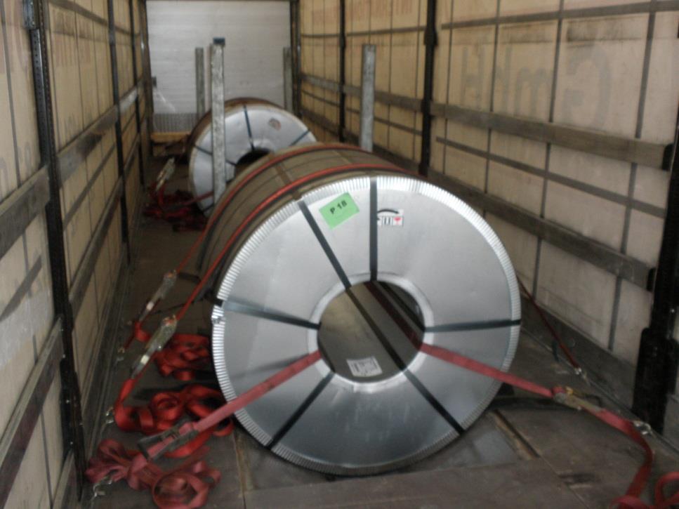
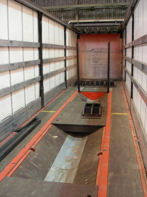
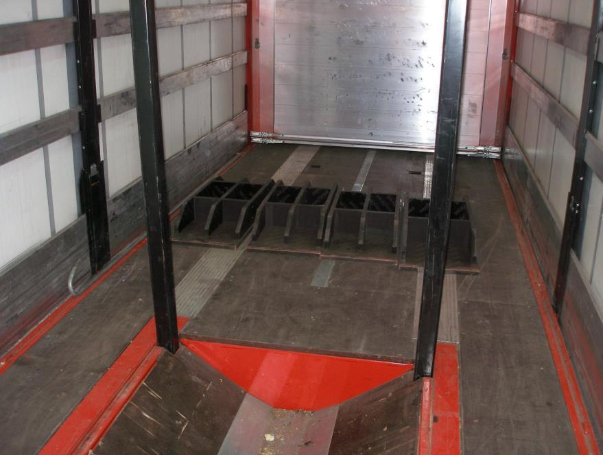
40 7 COILS LOADED IN A COIL-WELL WITH WINDING AXIS PARALEL TO LONGITUDINAL VEHICLE AXIS UP TO 20 TONNES 7.1 LOADING AND CARGO SECURING Coils are loaded by a crane into a coil-well. Coil-well is fitted with stanchion pockets for stanchions to block coils in forward direction wherever possible. Coil-well covers can be used to block other coils. In case that covers are of sufficient strength no lashing is necessary forwards. We do not recommend using more than one cover between two coils because they can tilt up during coil movement and blocking is inefficient. Always block coils with stanchions where possible! Unstable coils always block forwards with stanchions and secure against tilting rearwards! Load coils in one row and fill up the gaps with covers. Coils must be placed on rubber anti-slip mats! If the vehicle is fitted with stronger lashing points as 2000, we recommend using them. Not proper use of coil-well covers between neighbouring coils covers can tilt up during coil movement (left) and stable coil blocked by stanchions forwards and lashed by spring lashing through coil eye rearwards where straps are connected to stronger lashing points (right) 39

41 Cargo mass secured by 1 top-over lashing rearwards Ratchet type Standard tension force in lashing strap STF Banded greased or oiled sheets Packed sheets Banded sheets without surface coating-clean, sheet/wood, wood/plywood Banded sheets without surface coating or packed sheets with outer steel corners placed on rubber anti-slip mats For other lashing angles see tables in annex v tabuľkách Friction factor kg 1572 kg kg 1834 kg BLOCKING, SPRING OR LOOP LASHING 349 kg 436 kg 2096 kg 2621 kg kg 3931 kg kg 5242 kg TAB kg = 0,1 = 0,2 = 0,4 > 0,5 Lashing angles = Cargo mass secured by spring lashing through the coil eye in longitudinal direction SL1 Securing forwards Securing rearwards No. of lashing straps Banded greased or oiled sheets Packed sheets Banded sheets without surface coatingclean Banded sheets without surface coating or packed sheets with outer steel corners placed on rubber antislip mats Banded greased or oiled sheets Packed sheets Banded sheets without surface coating (or packed sheets with outer steel corners placed on rubber antislip mats) 1 3 t 3,8 t 5,7 t 7,7 t 5,4 t 7,7 t 23,1 t 2 6,1 t 7,7 t 11,5 t 15,4 t 10,8 t 15,3 t 28 t 3 9,2 t 11,5 t 17,3 t 23,1 t 16,1 t 23 t 4 12,3 t 15,3 t 23,1 t 28 t 21,5 t 28 t 5 15,4 t 19,2 t 28,9 26,9 t 6 18,4 t 23 t For other lashing angles see tables in annex TAB 1 TAB 3 TAB 5 TAB 7 TAB 2 TAB 4 TAB 6 Friction factor f = 0,1 f = 0,2 f = 0,4 f > 0,5 Lashing angles = max. 30, = max. 40 = max. 30, = max. 40 f = 0,1 f = 0,2 f = 0,4 40

42 7.2 SECURING EXAMPLES OF COILS IN A COIL-WELL 41

43 1. Stable coil of diameter smaller than transverse distance of stanchions loaded in a coil-well. Because of load distribution coil is moved rearwards and gap is filled by coil-well cover of sufficient strength to block the coil forwards. Coil is placed on rubber anti-slip mats and secured rearwards by spring lashing through the coil eye SL1 (light blue straps) or top-over lashings could be used for certain weights and contact surfaces. 2. Unstable coil in a coil-well placed on rubber anti-slip mats blocked against forward movement by stanchions. Spring lashings through coil eye SL1 (dark blue straps) are used against sliding rearwards and top-over lashings (yellow straps) are used against tilting rearwards. 3. Stable coil in a coil-well placed on rubber anti-slip mats blocked against forward movement by stanchions. Spring lashings through the coil eye SL1 (red straps) are used against rearwards sliding or top-over lashings could be used for certain weights and contact surfaces. 4. Stable coil of diameter smaller than transverse distance of stanchions is placed on anti-slip mats in a coil-well. Coil is blocked forwards by horizontal stanchions of sufficient strength secured against release and rearwards by spring lashings through the coil eye SL1 (light blue straps or top-over lashings could be used for certain weights and contact surfaces. 5. Stable coil not blocked by stanchions forwards secured forwards/rearwards by 4 spring lashings through the coil eye SL1 (red and dark blue straps) where each strap line is connected to separate lashing point on a vehicle platform. In case of heavier coils more lashings are necessary forwards and rearwards or stanchions blocking must be used. 6. Two coils placed on rubber anti-slip mats are blocked forwards by stanchions and coil-well cover of sufficient strength and between each other with a cover of sufficient strength. The whole group is secured rearwards by spring lashings through the last coil eye SL1 or top-over lashings could be used for certain weights and contact surfaces on both coils. 7. In case of doubts about cover strength it is possible to place more cover on each other and secured them by top-over lashing against sideways sliding. This is also suitable for blocking of unstable coils where covers are placed on each other between two coils. 42


44 7.3 SECURING OF UNSTABLE COILS BLOCKED BY STANCHIONS FORWARDS AGAINST TILTING REARWARDS Unstable coils must be secured against sliding and tilting! TOP-OVER LASHING AGAINST TILTING REARWARDS/FORWARDS CARGO MASS SECURED BY 1 LASHING Lashings must be symmetrically positioned relative to the centre of the coil - = Tension force in lashing line Lashings must be symmetrically positioned relative to the centre of the coil - = Tension force in lashing line d / b d / b kg kg kg kg kg kg kg kg kg kg kg kg 1, , , , , , , , , , , , , , , , , , , , , , Other lashing angles are given in TAB 16, TAB 17 and TAB 18 in annex. 43

45 SPRING LASHING AGAINST TILTING REARWARDS/FORWARDS In case of doubts about the strength of the stanchions also consider the forward direction (darkblue strap). Coil mass with ratio d/b secured against tilting rearwards by 1 spring lashing/2lines according to the figure above d/b = max. 80, x = max. 60 2,22 32 t 4,00 4 t 2,50 14,5 t 5,00 2,8 t d/b 2,86 8,7 t 6,67 2 t 3,33 5,7 t 10,00 1,4 t Coil mass with ratio d/b secured against tilting forwards by 1 spring lashing/2lines according to the figure above d/b = max. 80, x = max. 60 1,33 27 t 2,50 3,6 t 1,43 23,4 t 2,86 2,9 t 1,54 14,6 t 3,33 2,3 t 1,67 10,2 t d/b 4,00 1,8 t 1,82 7,6 t 5,00 1,4 t 2,00 5,8 t 6,67 1,1 t 2,22 4,6 t 10,00 0,8 t 44
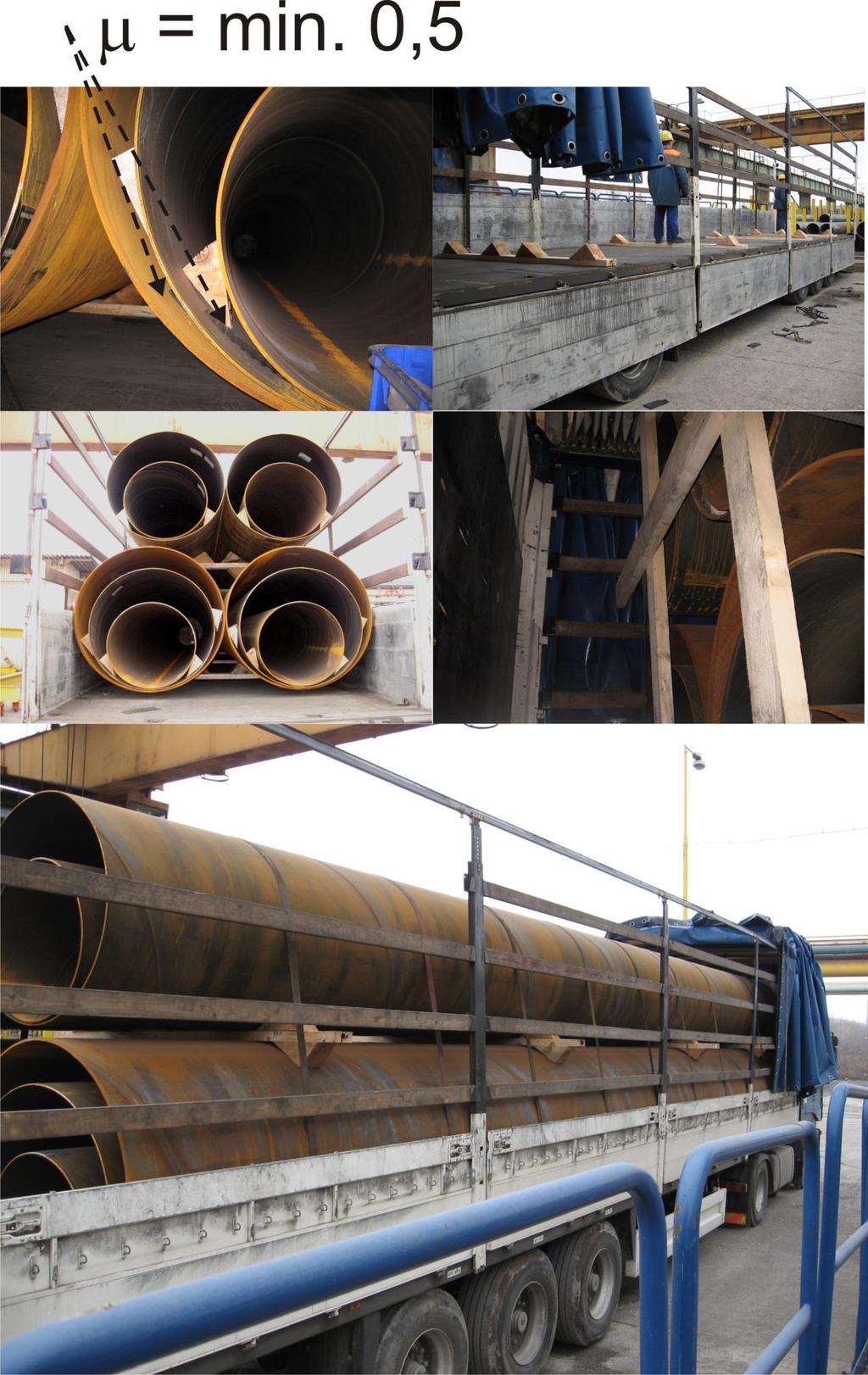
46 8 SPIRAL-WELDED STEEL PIPES 8.1 LOADING Pipes are loaded on wooden battens. At the beginning and at the end of the loading platform two battens are placed with pipes overhang about mm. Besides it is necessary to place another 2 battens between them of equal distance. Battens are fitted with nailed wedges. Battens between layers have wedges nailed from both sides. If there are no gaps between the pipes in one layer the outer pipes are secured by wedges only. If there are gaps between the pipes in one layer each pipe must be secured by wedges from both sides. Place the first layer of pipes on wooden battens. After the loading of the first layer place the battens with nailed wedges from both sides in such a way that they secure the pipes in upper and lower layer. Place next layer of pipes on this battens. This procedure repeats in regard to number of pipes to be loaded. By loading secure the pipes against rolling by wedges. Pipes must be loaded firstly against the headboard but if load distribution doesn t allow this it is necessary to use protective wooden grid! 8.2 CARGO SECURING It is difficult to achieve proper and efficient securing of pipes. It is important that well secured wedges prevent pipes from rolling also during unloading when lashings holding the pipes during carriage are loosened. It is important to use sufficiently strong wooden battens to prevent breaking and loosening of the stability of the whole stack of pipes. Mass of secured cargo by 1 top-over lashing against sliding sideways/rearwards Ratchet type Standard tension force in lashing strap STF Steel/wood, wood/plywood clean Rubber anti-slip mats between cargo and platform kg kg kg kg kg kg For other lashing angles see tables in annex TAB kg Friction factor = 0,4 > 0,5 Lashing angles = In case of cargo mass of 26 tonnes 26/3,21 = 9 lashing straps with long handle ratchets with tension force of 500 are necessary to secure the whole cargo against sliding sideways. It is necessary to consider additional pressure from lashings on outer pipes. By 9 lashings and force 500 additional pressure on outer pipes is 4,5 tonnes. If drivers use extension bars for ratchets then force
47 above 1000 is possible and additional pressure of 9 tonnes (+ pipes mass) on outer pipes which can damage wooden battens if the pipes in layers are not placed exactly on each other. Mass of secured cargo by round spring lashing SL2 Securing forwards Securing rearwards No. of lashing straps steel/wood, wood/plywood clean rubber anti-slip mats in each sliding layer steel/wood, wood/plywood clean 6,5 t 8,6 t - 13 t 17,3 t 26 t 3 19,5 t 26 t 4 26 t For other lashing angles see tables in annex TAB12 TAB 14 TAB 13 Friction factor f = 0,4 f = 0,5 f = 0,4 Lashing angles = max. 30, x = max. 5 Cargo mass secured by pairs of loop lashing sideways for two variants of loop lashing but always a minimum of 3 pairs of loop lashings Variant LL1 Variant LL2 No. of pairs of loop lashings steel/wood, wood/plywood clean steel/wood, wood/plywood clean 2 27 t 21,1 t 3 27 t 27 t For other lashing angles see tables in annex TAB6 TAB6 f = 0,4 f = 0,4 1=max.90, 2=max.20, y= top line over the cargo 2...bottom line under the cargo 1=max. 90, 2=max.20, y=0, x= top line over the cargo 2...bottom line under the cargo Use of front protective grid is necessary when: - Pipes are not directly placed against headboard and mainly pipes loaded in each other. - Protective grid can be substituted by cargo securing net of sufficient strength. - For certain loadings spring lashing with pallets can be used occasionally. For loadings where it is not possible to loop lash the layers of the cargo use loop lashing of the whole cargo by minimum 6 lashing straps for securing sideways. 46

48 47
")
49 8.3 SELECTED LOADING COMBINATIONS OF PIPES IN USSK (MASS IS VALID FOR 12 METERS PIPES) 48
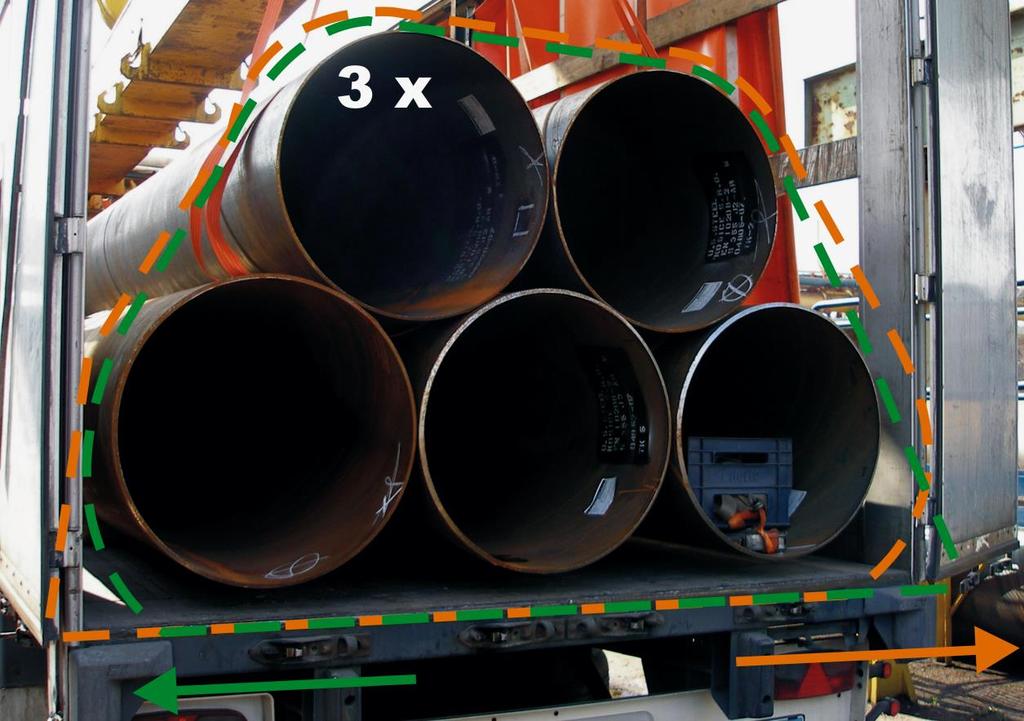
50 Eccentrically loading (stowage 14, 15) Eccentrically loading of pipes is always secured by loop lashings sideways. Minimum 3 pairs of loop lashings shall be used for the whole cargo and 3 loops for top pipe against movement to one side. Loading of pipes of diameter 864/914 mm (stowage 11) Cargo securing sideways shall be done by 3 pairs of loop lashings for bottom layer and 3 pairs of loop lashings for top layer of pipes. Pipes loaded in pipes bed (stowage 9, 10, 12, 13) Pipes loaded in pipes bed shall be secured by 4 round turn lashings with bottom layer close to wooden battens to release the pressure on outer wedges which is increasing with the application of top-over lashings. For loading combination 13 the gap between two pipes must be filled. In case that pipes are loaded in pipes bed then contact surface is steel-steel therefore use of rubber anti-slip mats is necessary on such surface. Pipes loaded broader and top pipe loaded in pipes bed (stowage 16, 17) Pipes loaded in upper layer are loaded on 6 wooden battens and pipes in bottom layer on 4 wooden battens. Top 3 pipes must be lashed by 2 round turn lashings with min. 8 mm chains (LC=4000) (stowage 16) or 4 lashing straps and wooden support of top middle layer by 2 vertical wooden blocks 100x100 mm nailed to outer horizontal wooden battens. These two wooden blocks must be of accurate length to exactly fill the gap between the platform and top middle pipe. Without such securing top middle pipe can fall down and push out the vehicle sides

51 SECURING EXAMPLES OF SELECTED LOADING COMBINATIONS OF PIPES 1. Pipes blocked by headboard of sufficient strength (EN XL) forwards and secured sideways by top-over lashings (yellow straps). 2. Pipes of different length not blocked forwards secured by round spring lashings with pallets where wooden blocks can be inserted under straps. No. of spring lashings is according individual mass of the layers. Cargo is secured sideways by top-over lashings. 50

52 3. Cargo securing of pipes loaded into each other by 4 spring lashings SL2 (8 lines) with wooden grid. Two spring lashings of bottom/top layer have the same length. Cargo is secured sideways by top-over lashings. Pipes inside each other are always placed on rubber anti-slip mats and wedged against transverse rolling. 4. Securing of eccentrically loading of pipes by spring lashings SL2 (8-10 lines) in combination with wooden grid forwards. Securing sideways is done by 3 pairs of loop lashings LL1/LL2 for the whole cargo and by 3 loops of top pipes against movement to one side. Rubber anti-slip mats are used between steel/steel surface. 51
53 52
Road Standards Restraint Guidelines. Guidelines for the securing of steel products for external road transport.
 Road Standards Restraint Guidelines Guidelines for the securing of steel products for external road transport. Tata Steel Supply Chain Europe Revision 1.0 EN Outbound Department Date : 01/08/2015 Valid
Load Securing at Mohn Media Mohndruck GmbH
 EXTERN Last updated: 1.2018 Guideline Load Securing at Mohn Media Mohndruck GmbH Content 2 Preface Scope Legal foundations 3 Vehicle requirements General vehicle requirements Securing Material Truck condition
INFORMATIVE MATERIAL 5 QUICK LASHING GUIDE. Cargo securing on CTUs for transports on Road, Combined Rail and in Sea Area A, B & C SEA AREAS
 Page 65 INFORMATIVE MATERIAL 5 QUICK LASHING GUIDE Cargo securing on CTUs for transports on Road, Combined Rail and in Sea Area A, B & C SEA AREAS A B C H s 8 m 8 m < H s 12 m H s > 12 m Baltic Sea (incl.
LOAD SAFETY SERIES Information Sheet
 LOAD SAFETY SERIES Information Sheet March 2016 What the Law requires Under Health and Safety Legislation, a vehicle is a place of work. The law requires that workplaces are maintained in a condition that
LOAD SAFETY SERIES Information Sheet
 LOAD SAFETY SERIES Information Sheet March 2016 What the Law requires Under Health and Safety Legislation, a vehicle is a place of work. The law requires that workplaces are maintained in a condition that
Packaging Information Reels
 PERFORMANCE PIPE REELS PRUCTS Size Nominal Maximum Conduit Length Reel Hub Reel Width Outside Maximum Reels Per Truck Potential Feet Per Truck Trailer Requirement 1 1.315 15,000 96 30 48 12 180,000 48
SECTION 11 INTERMODAL EQUIPMENT
 SECTION 11 INTERMODAL EQUIPMENT ROA MANUAL SCHEDULE OF AMENDMENTS SECTION 11 AMENDMENT NUMBER PAGES AMENDED AMENDMENT SUMMARY DATE ISSUED TABLE OF CONTENTS Section Description Page No. 11.1 SCOPE... 11-1
HIGHWAY TRAFFIC ACT COMMERCIAL VEHICLE (CARGO SECUREMENT) REGULATIONS
 REGULATIONS") c t HIGHWAY TRAFFIC ACT COMMERCIAL VEHICLE (CARGO SECUREMENT) REGULATIONS PLEASE NOTE This document, prepared by the Legislative Counsel Office, is an office consolidation of this regulation, current to
c t HIGHWAY TRAFFIC ACT COMMERCIAL VEHICLE (CARGO SECUREMENT) REGULATIONS PLEASE NOTE This document, prepared by the Legislative Counsel Office, is an office consolidation of this regulation, current to
North American Cargo Securement Standard. Model Regulation. May 2012 Edition
 North American Cargo Securement Standard Model Regulation May 2012 Edition Table of Contents Part 1 - Standard Application and Objectives...4 1.1 Application... 4 1.2 Requirement... 4 1.3 Performance Criteria...
Important. Contents. Contact us:
 Operator's Manual Third Edition Third Printing Important Read, understand and obey these safety rules and operating instructions before operating this machine. Only trained and authorized personnel shall
S e c t i o n C - Restraining Loads on Vehicles
 SECTION C CONTENTS RESTRAINING LOADS ON VEHICLES 1 HOW MUCH LOAD RESTRAINT? 58 2 TIE-DOWN 60 2.1 Friction ----------------------------------------------------------- 60 2.2 Applying Tie-down Lashings ---------------------------------
Important. Contents. Contact us:
 Operator's Manual First Edition Ninth Printing Important Read, understand and obey these safety rules and operating instructions before operating this machine. Only trained and authorized personnel shall
Lashing. SpanSet Truxafe. Directions for use
 Lashing SpanSet Truxafe Directions for use GB TruXafe Instructions for use Introduction Dear Customer, We congratulate you on your purchase of TruXafe. You have chosen a quality product by SpanSet, which
South Dakota Highway Patrol District 4 Motor Carrier Services
 South Dakota Highway Patrol District 4 Motor Carrier Services This applies to all trucks, truck tractors, semitrailers, full trailers, and pole trailers. Each of these motor vehicles must, when transporting
RAMPS. Active life means you are always on the move. REESE Explore has the perfect solution to get your gear on the road safely.
 FOR EVERY ADVENTURE Active life means you are always on the move. REESE Explore has the perfect solution to get your gear on the road safely. ALUMINUM Aluminum Ramps... 244 Zero-Turn Mower Ramps... 244
The Security of Loads Regulations
 1 The Security of Loads Regulations Repealed by chapter H-3.01 Reg 3 (effective November 10, 1999). Formerly Chapter H-3.1 Reg 14 (effective April 1, 1993) as amended by Saskatchewan Regulations 37/93.
National Safety Code Standard 10 Cargo Securement. Guidance and Interpretations
 National Safety Code Standard 10 Cargo Securement Guidance and Interpretations Updated May 2016 Disclaimer The guidance which is provided in this document is offered for convenience only. For accurate
THE STRESS OF LASHING POINTS IN FULL- LOADED 3,5-TONNE VAN DURING EMERGENCY BRAKING
 THE STRESS OF LASHING POINTS IN FULL- LOADED 3,5-TONNE VAN DURING EMERGENCY BRAKING Ján ZÁMEČNÍK, Juraj JAGELČÁK 1 Introduction and description of the tests During the emergency the forces occuring on
Z TECHNICAL INSTRUCTIONS
 ÍNDICE: Z40 2.0 TECHNICAL INSTRUCTIONS 1.- Error list 2.- Replace the control board 3.- Opening the machine 4.- Replace the power board 5.- Dismantling motor and gear box 6.- Assembly of gear box 7.- Pushing
Operators manual Bumpa 8 metre 110v Bumpa 10 metre 110v
 Operators manual Bumpa 8 metre 110v Bumpa 10 metre 110v SAFETY RULES Mk3 Bumpa Conveyor Danger Failure to obey the instructions and safety rules in this manual will result in death or serious injury. Do
On-A-Roll Lifter Instruction Manual for Standard Models Read Before Use!
 On-A-Roll Lifter Instruction Manual for Standard Models Read Before Use! Important instructional, safety and precautionary information! It is the user s responsibility to exercise good judgment, common
LKS300/LKS450 OPERATOR S MANUAL
 LKS300/LKS450 OPERATOR S MANUAL SAFETY RULES SHIFTA 300/450 Conveyor DANGER Failure to obey the instructions and safety rules in this manual will result in death or serious injury. Do Not Operate Unless:
Operators manual Hoddi 6 metre 110v Bumpa 8 metre 110v Bumpa 10 metre 110v
 Operators manual Hoddi 6 metre 110v Bumpa 8 metre 110v Bumpa 10 metre 110v SAFETY RULES Mk3 Bumpa Conveyor Danger Failure to obey the instructions and safety rules in this manual will result in death or
KRONE - Profi Liner. Quantity: 2 Type: SDP 27 elp3-cs. Technical specification/description
 KRONE - Profi Liner Quantity: 2 Type: SDP 27 elp3-cs Technical specification/description FIN-registration (Finland) Without country symbol sticker Lettering on manufacturers plate: Type: SD National type
Road Inbound Standards Tata Steel Strip UK
 Road Inbound Standards Tata Steel Strip UK Table of Contents 1. Introduction 2. Site Controls 2.1 Site Access / Procedures 2.2 Personal Behaviour 2.3 Personal Protective Equipment 2.4 Site Rules 3. Trailer
SL15/20-6 AND SL15/20-10 INSTALLATION INSTRUCTIONS
 STOWAWAY SideLoader Tailgates By THIEMAN SL15/20-6 AND SL15/20-10 INSTALLATION INSTRUCTIONS! IMPORTANT! KEEP IN VEHICLE! READ AND UNDERSTAND THE CONTENTS OF THIS MANUAL BEFORE OPERATING THE EQUIPMENT.
Property of American Airlines
 Date Maintenance Check list This document describes the inspection and maintenance of the Power Stow Rollertrack. Maintenance refers to a time span. The operation hours are shown on the Power Stow Display
PRECISMECA - MONTAN Gesellschaft für Fördertechnik mbh. Documentation Operating Instructions. Rollers
 PRECISMECA - Gesellschaft für Fördertechnik mbh Documentation Operating Instructions Rollers Operating Instructions Index No.: T311-00 Page: 1 of 1 Section Document No. Pages Preface Safety Technical data
The Security of Loads and Trip Inspection Regulations
 SECURITY OF LOADS AND TRIP INSPECTION H-3.01 REG 4 1 The Security of Loads and Trip Inspection Regulations Repealed by Chapter H-3.01 Reg 11 (effective April 25, 2013) Formerly Chapter H-3.01 Reg 4 (effective
Operating instructions ErgoPack 600 E
 Operating instructions ErgoPack 600 E Operation of the device is only permitted if the operating instructions have been carefully read and understood before use! Declaration of conformity EU declaration
<THESE INSTRUCTIONS MUST BE GIVEN TO THE END USER> B&W
 B&W Trailer Hitches 6 Hawaii Rd / PO Box 86 Humboldt, KS 66748 P:60.473664 F:60.869.903 Turnoverball Gooseneck Hitch Installation Instructions MODEL 08
DESCRIPTION, TECHNICAL SPECIFICATION, OPERATION, AND MAINTENANCE MANUAL FOR THE ISU-SYSTEM INNOVATIVER SATTELANHÄNGER UMSCHLAG
 DESCRIPTION, TECHNICAL SPECIFICATION, OPERATION, AND MAINTENANCE MANUAL FOR THE ISU-SYSTEM INNOVATIVER SATTELANHÄNGER UMSCHLAG INNOVATIVE SEMITRAILER HANDLING UNIT Seite 1 / 27 DESCRIPTION, TECHNICAL SPECIFICATION,
Doleco USA Textile Link Tiedown Assembly
 Created: Sept. 27, 2018 Summary This Inspection Bulletin provides guidance for identifying and inspecting the Doleco USA textile link tiedown assembly (used for cargo securement on trucks or trailers)
Safety and Assembly instructions
 Edition 1.0 2015 621-002 Fliptop MAXI Safety and Assembly instructions Roof Systems Thank you for having purchased a Fliptop MAXI, here are the instructions for installation of our product. it occurring
Kögel Flatbed Trailer
 Kögel Flatbed Trailer Illustration similar / can include special equipment Why so much talk about the art of engineering? Because there is genius in it and because prowess is behind it. Comprehensive competence
Figure 1 Pipe bunk. -Articles of cargo placed beside each other and secured by transverse tie-downs must either be 3 of 14
 All trailers hauling Tubular goods, must be equipped with a minimum of four (4) Samson posts/stanchions integrated into and adequately secured to the side rails of the trailer and/or Pipe Bunks similar
INSTALLATION INSTRUCTION 88146
 INSTALLATION INSTRUCTION 88146 Rev H FOR RANCHO SUSPENSION SYSTEM RS6547: 4WD SUBURBAN/YUKON XL, 4WD TAHOE/YUKON, & 4WD AVALANCHE READ ALL INSTRUCTIONS THOROUGHLY FROM START TO FINISH BEFORE BEGINNING
Shipping Systems Division
 Shipping Systems Division Keeping you and your load secure is our job! We do this by manufacturing a blend of field-proven products to developing some of the industry s most innovative new systems for
ALUMINUM CARGO CARRIER WITH FOLDING RAMP
 ALUMINUM CARGO CARRIER WITH FOLDING RAMP OWNER S MANUAL WARNING: Read carefully and understand all ASSEMBLY AND OPERATION INSTRUCTIONS before operating. Failure to follow the safety rules and other basic
<THESE INSTRUCTIONS MUST BE GIVEN TO THE END USER> B&W
 B&W Trailer Hitches 1216 Hawaii Rd / PO Box 186 Humboldt, KS 66748 P:620.473.3664 F:620.869.9031 Turnoverball Gooseneck Hitch Installation Instructions
Lifting tool forloadbearing sheet
 www.ruukki.com Lifting tool forloadbearing sheet User manual Contents Description and intended use... 2 Ce-marking... 2 Lifting capacity... 3 Parts... 3 Load features... 4 Making the lift... 4 Preparing
innovative safety Lashing chain systems and accessories in G10 quality
 innovative safety Lashing chain systems and accessories in G10 quality (for load securing in accordance with EN 12195-3) Introduction Pewag Chain Lashing Systems for the Road Transport Industry Load lashing
INSTRUCTION MANUAL 16K - Fifth Wheel Hitch
 You can take it with you. INSTRUCTION MANUAL 16K - Fifth Wheel Hitch Product No. 30047 DEALER/INSTALLER: END USER: (1) Provide this Manual to end user. (2) Physically demonstrate hitching and unhitching
Important. Contents. Contact us:
 Operator's Manual Second Edition First Printing Important Read, understand and obey these safety rules and operating instructions before operating this machine. Only trained and authorized personnel shall
Transport solutions for HEAVY HAULAGE. Low loaders KAPITEL 1
 Transport solutions for HEAVY HAULAGE Low loaders KAPITEL 1 OVERVIEW SERIES LOW LOADERS THE ALL-ROUNDER INDUSTRIES PLATFORM SEMI-TRAILERS SEMI LOW LOADERS LOAD PLATFORM Heavy construction machinery and
Curtainsider semitrailer S.CS MEGA with VARIOS TopTechnology. Configurator
 Curtainsider semitrailer S.CS MEGA with VARIOS TopTechnology Configurator Trailer Services Technology Your MEGA Trailer configured individually Using this brochure, you are able to chose the Curtainsider
innovative safety Lashing chain systems and accessories in G10 quality
 innovative safety Lashing chain systems and accessories in G10 quality (for load securing in accordance with EN 12195-3) Introduction Pewag Chain Lashing Systems for the Road Transport Industry Load lashing
HM WIND TURBINE. Operation Manual. **Please read the manual carefully before using **
 HM4.0-3000 WIND TURBINE Operation Manual **Please read the manual carefully before using ** - 1 - HM4.0-3KW operation manual.doc 1. The aim of Application Use wind energy to generate electricity and charge
The GK units differ from the LK units in that the springs of the GK units have a spring eye at the front.
 01 09 Installation guidelines Mechanical suspension units GK LK GN0032-0 Mechanical suspension units GK LK The GK units differ from the LK units in that the springs of the GK units have a spring eye at
USER MANUAL Lifting tool for load-bearing sheet.
 USER MANUAL Lifting tool for load-bearing sheet www.ruukki.com Contents DESCRIPTION AND INTENDED USE 3 CE-MARKING 3 LIFTING CAPACITY 4 PARTS 4 LOAD FEATURES 6 MAKING THE LIFT 6 PREPARING A LIFT 7 LIFTING
Installation and Service Manual
 RESIDENTIAL PLATFORM LIFTS RPL400 / RPL600 Installation and Service Manual WARNING! STRICT ADHERENCE TO THESE INSTALLATION INSTRUCTIONS IS REQUIRED to promote the safety of those installing this product,
SERVICE GUIDE AGRICULTURAL TRACK REMOVAL INSTALLATION INSPECTION ALIGNMENT CPB-305
 SERVICE GUIDE CPB-305 AGRICULTURAL TRACK AGCO Challenger MT735, 745, 755, 765 AGCO Challenger MT835, 845, 855, 865, 875 REMOVAL INSTALLATION INSPECTION ALIGNMENT TABLE OF CONTENTS Table of Contents Introduction...
AMY SAYS: Drop Forged Pear Link. Eyes are tapered and an eye buffer is sewn in the eye for better fit and wear. Anatomy of an
 AMY SAYS: Drop Forged Pear Link Eyes are tapered and an eye buffer is sewn in the eye for better fit and wear. AMY Anatomy of an V Sling Full two-ply web bodies which allow for only one splice. (no edge
01 09 Installation guidelines Air suspension units GL70 GL70HD GL70L GN Air suspension units GL70 GL70HD GL70L
 01 09 Installation guidelines Air suspension units GL70 GL70HD GL70L GN0031-1 Air suspension units GL70 GL70HD GL70L can be identified by the hanger brackets with a welded-on support for the eccentric
LSU University Safety Manual Section IV, Part C Stairs and Ladders. C. Stairs & Ladders
 C. Stairs & Ladders 1. General Requirements a. A stairway or ladder must be provided at all worker points of access where there is a break in elevation of 19 inches (48 cm) or more and no ramp, runway,
Instructions for MB832 Manual Barrier Ver0614
 Instructions for MB832 Manual Barrier Ver0614 Read all the instructions before starting It is recommended that Locktite Blue brand thread sealant be used for all arm and pivot bolts as added protection
Models: DC Electric Vibrators. Operating Instructions CEG CEG CEG CEG CEG
 DC Electric Vibrators Operating Instructions Global External 12-Volt DC Electric Vibrators Intermittent Use Only Models: CEG-1800-12 CEG-2200-12 CEG-2800-12 CEG-3600-12 CEG-4200-12 INDUSTRIAL ELECTRIC
EXECUTIVE COUNCIL 19 JULY At a Meeting of the Executive Council in Committee, Present: EC
 221 At a Meeting of the Executive Council in Committee, Present: EC2005-380 ELECTION ACT RETURNING OFFICER ELECTORAL DISTRICT NO. 10 TO APPOINT Pursuant to section 9 of the Election Act R.S.P.E.I. 1988,
platform trailer Driving innovation SAFETY QUALITY INNOVATION Broshuis B.V. Industrieweg AD, Kampen
 platform trailer Driving innovation Broshuis B.V. Industrieweg 22 8263 AD, Kampen www.broshuis.com SAFETY QUALITY INNOVATION Introduction content Products 3-axle hydraulically operated flat trailer 4-axle
2. Runway & Crane System
 2. Runway & Crane System The crane runway girders, crane, columns and building frames can all be regarded as components of the overall crane installation. The individual components cannot be designed in
IMPORTANT WARRANTY & INSTALLATION INSTRUCTIONS ATTACHED
 IMPORTANT WARRANTY & INSTALLATION INSTRUCTIONS ATTACHED Please Forward All Attached Information to Consumer Warranty Not Valid Unless Returned to CORSA Performance STOP Please take time to read and understand
Mechanical load securing
 With our WISTRA products in the area of mechanical load protection aids we offer quick and safe options of form-fit load securing for the most diverse means of transport. Many items in this product range
SERIES A & AA ROLLER DOORS INSTALLATION GUIDE
 SERIES A & AA ROLLER DOORS INSTALLATION GUIDE THESE INSTRUCTIONS ARE PROVIDED FOR USE BY EXPERIENCED INSTALLERS OF GARAGE DOORS BY UNDER-TAKING THE INSTALLATION OF THIS DOOR, THE INSTALLER UNDERSTANDS
Armourtex Protection
 Armourtex Protection Armourtex sleeves Suitable applications and benefits Chains Wire rope Polyester webbing slings and lashings Safe Lifting Procedure High resistance to abrasion Extremely cut resistant
Spring hangers, spring supports
 Spring hangers, spring supports 2 spring Spring hangers, supports PRODUCT 2 GROUP Spring hangers, spring supports Contents Page Field of application...2.1 Overview of spring hangers and spring supports...2.3
IMPORTANT WARRANTY & INSTALLATION INSTRUCTIONS ATTACHED
 IMPORTANT WARRANTY & INSTALLATION INSTRUCTIONS ATTACHED Please Forward All Attached Information to Consumer Warranty Not Valid Unless Returned to CORSA Exhaust We ask that you take a few moments to compete
Moving? No Limits! Industrial and Heavy-Duty Trailers
 Industrial and Heavy-Duty Trailers The suitable trailer for goods of all shapes and sizes Whether you are looking for a standard type of trailer or you require a special, customised solution, SEACOM Trailer
Property of American Airlines
 Date Maintenance Check list The inspection and preventive maintenance schedule of the Power Stow Rollertrack is as follows: Daily (10 hrs), Weekly (50 hrs.), every 6 months ( hrs.), yearly (1 hrs.) and
FLEXIBLE CABLES For Special Applications PRODUCT CATALOGUE
 www.suncables.co FLEXIBLE CABLES For Special Applications PRODUCT CATALOGUE www.suncables.co ABOUT SUN CABLES is a renowned brand owned by Nangalwala Industries (P) LTD (formely known as Nangalwala Impex
CRANE RATING MANUAL HTC
 SERIAL NUMBER: CRANE RATING MANUAL 5---Section Boom For Replacement, Order Part Number: N3P0199 (031907) R Link-Belt is a registered trademark. 1of244 N3P0200 Table Of Contents Page Contents 3---4 Operating
CommScope MULTILAYERED 289-TYPE INSTALLATION INSTRUCTIONS
 CommScope MULTILAYERED 289-TYPE 63-460-32-03 BUILDING ENTRANCE PROTECTOR (BEP) Issue 5, February 2004 Material ID 847 364 882 INSTALLATION INSTRUCTIONS General This instruction sheet provides procedures
CARGO SECUREMENT REGULATIONS FOR THE CONCRETE PIPE INDUSTRY
 CARGO SECUREMENT REGULATIONS FOR THE CONCRETE PIPE INDUSTRY TABLE OF CONTENTS The information presented is synthesized from the Regulatory Guidance for the Federal Motor Carrier Safety Regulation s Part
Technical Publications IWP. Operator's Manual. Third Edition, First Printing Part No
 Technical Publications IWP Operator's Manual Third Edition, First Printing Part No. 35054 Operator s Manual Third Edition Important Read, understand and obey these safety rules and operating instructions
EGT Plus Instructions
 Computech Systems, Inc. 29962 Killpeck Creek Ct. Charlotte Hall, MD 20622 301-884-5712 EGT Plus Instructions The Computech Systems EGT Plus is designed to monitor not only exhaust gas, liquid, tire and
Regulations relating to the Use of Vehicles, Chapter 5
 Regulations relating to the Use of Vehicles, Chapter 5 Section 5-1 Limits specified on registration etc. A vehicle must not be used or authorised for use if the axle load, load from an axle combination,
DESIGN. I. Loading and Speed
 DESIGN D.Wren designs Solid Rubber & Duramatic Tyres as per customer s requirements at its computer aided design facility based on the following data. Selection of Solid Tyres by the users should be based
Model 320 / 320A Hinge Assembly
 MANUFACTURING CO. THE FIRST NAME IN QUALITY COUPLINGS Installation, Inspection, Operation & Maintenance Guide Model 320 / 320A Hinge Assembly IMPORTANT Read these instructions completely before installing,
Translation of the Original operating instructions Lifting device Z 70 /...
 Translation of the Original operating instructions Lifting device Z 70 /... Content 1. Lifting device / Correct use according to regulations 2. Basic principles 3. General information 4. Special remarks
SUSPENSION 04 CLAMPS
 SUSPENSION CLAMPS 04 4 SUSPENSION CLAMPS 57 Contents General... 58 Suspension clamp trunnion type, forged,... 63 Suspension clamp trunnion type, forged, with bigger angle of deflection, for aluminium based
Cargo Securement General Overview. Monthly Training Topic NV Transport, Inc. Safety & Loss Prevention
 Cargo Securement General Overview Monthly Training Topic NV Transport, Inc. Safety & Loss Prevention Purpose of Cargo Securement The purpose of this presentation is to learn how to: Apply the securement
DEMOUNTABLE BODY INSPECTION PROCEDURE Follow Detailed Instructions Inside for Each Step
 DEMOUNTABLE BODY INSPECTION PROCEDURE Follow Detailed Instructions Inside for Each Step Inspection Date: Inspected By: Serial #: Unit #: INSPECT: Inspected OK Needs Repair Comments Front Locking Bar Rear
Work Platforms. Operators Manual Warning Stickers ANSI Standards. ( Model # MWP 4x4 ) ( Model # MWP 4x6 ) ( Model # MWP 4X8 ) ( Model # MWP 4x116 )
 ( Model # MWP 4x6 ) ( Model # MWP 4X8 ) ( Model # MWP 4x116 )") Work Platforms ( Model # MWP 4x4 ) ( Model # MWP 4x6 ) ( Model # MWP 4X8 ) ( Model # MWP 4x116 ) Operators Manual Warning Stickers ANSI Standards Marv Haugen Enterprises 1851 Heartland Ave. 1851 Heartland
Work Platforms ( Model # MWP 4x4 ) ( Model # MWP 4x6 ) ( Model # MWP 4X8 ) ( Model # MWP 4x116 ) Operators Manual Warning Stickers ANSI Standards Marv Haugen Enterprises 1851 Heartland Ave. 1851 Heartland
BX4330 Acclaim Tow Bar Operator Manual & Installation Instructions
 Operator Manual & Installation Instructions (5,000 lb) 2 Inch Coupler General Information DO NOT INSTALL, OPERATE OR USE THIS EQUIPMENT UNTIL THE FOLLOWING OPERATING AND SAFETY INSTRUCTIONS HAVE BEEN READ
INSTALLATION INSTRUCTION 88148
 INSTALLATION INSTRUCTION 88148 Rev C For Rancho Suspension Systems RS6548, RS6549 & RS6550: GM 2500HD, 2500, and 1500HD Trucks READ ALL INSTRUCTIONS THOROUGHLY FROM START TO FINISH BEFORE BEGINNING INSTALLATION
OWNER S MANUAL. Sentry & Sentry CT THREE YEAR WARRANTY. Phone: ( ) Fax: (605) SAFETY INSTRUCTIONS
 Fax: (605) SAFETY INSTRUCTIONS") OWNER S MANUAL Sentry & Sentry CT HARD ROLL-UP TRUCK BED COVER SAFETY INSTRUCTIONS 1. Do not place objects on or against cover or framework. 2. Do not tie cargo to truck bed cover framework. 3. Never allow
OWNER S MANUAL Sentry & Sentry CT HARD ROLL-UP TRUCK BED COVER SAFETY INSTRUCTIONS 1. Do not place objects on or against cover or framework. 2. Do not tie cargo to truck bed cover framework. 3. Never allow
Skid against Curb simulation using Abaqus/Explicit
 Visit the SIMULIA Resource Center for more customer examples. Skid against Curb simulation using Abaqus/Explicit Dipl.-Ing. A. Lepold (FORD), Dipl.-Ing. T. Kroschwald (TECOSIM) Abstract: Skid a full vehicle
CAL Ramp Operations Safety Notes
 CAL Ramp Operations Safety Notes Ramp Security & Safety 1. Persons who need to access the aircraft SHALL hold a valid identification badge on the front of the outer garment above the waist. 2. Smoking
RTC 8050 Series II. 50 ton (45.36 metric tons) Telescopic Boom Rough Terrain Crane
 Telescopic Boom Rough Terrain Crane") Telescopic Boom Rough Terrain Crane RTC 85 Series II 5 ton (45.36 metric tons) Boom and Fly Capacities for this machine are listed by the following sections. Working Range Diagram 35.5 to 6.3 (1.82 18.38
Telescopic Boom Rough Terrain Crane RTC 85 Series II 5 ton (45.36 metric tons) Boom and Fly Capacities for this machine are listed by the following sections. Working Range Diagram 35.5 to 6.3 (1.82 18.38
BURQUIP INTERNATIONAL (PTY) LTD
 LTD") Chapter 6 Transmission The transmission system comprises all of the components that transfer the force and movement from the Braked Coupler to the inertia brakes in the axles. Fit the axles to the trailers
Chapter 6 Transmission The transmission system comprises all of the components that transfer the force and movement from the Braked Coupler to the inertia brakes in the axles. Fit the axles to the trailers
ST11 Structural Straightening
 Uniform Procedures For Collision Repair ST11 Structural Straightening 1. Description This procedure describes repair methods and inspection requirements for straightening structural parts using hydraulic
This lift will not operate with the generator engaged.
 WARNING 40' GENIE S40 PERSONNEL BOOM LIFT Any piece of equipment can be dangerous if not operated properly. YOU are responsible for the safe operation of this equipment. The operator must carefully read
INSTRUCTION MANUAL 16K - Fifth Wheel Hitch
 You can take it with you. INSTRUCTION MANUAL 16K - Fifth Wheel Hitch Product No. 30047 DEALER/INSTALLER: END USER: (1) Provide this Manual to end user. (2) Physically demonstrate hitching and unhitching
NOTE: Skids and all hardware for the skids are located in the plow blade box.
 Description Item Qty. Part# 0 0 ATV PUSH TUBE AND BLADE MOUNTING INSTRUCTIONS P/N: 0-0 CUSTOMER MUST RECEIVE A COPY OF THIS INSTRUCTION SHEET AT THE TIME OF SALE NOTE: Skids and all hardware for the skids
Doprava a spoje elektronický časopis Fakulty prevádzky a ekonomiky dopravy a spojov Žilinskej univerzity v Žiline, ISSN
 LOADING AND CARGO SECURING DEVICES IN STANDARD FORTY FOOT GENERAL PURPOSE MARITIME CONTAINERS Juraj Jagelčák 1, Ján Vrábel 2 a Miroslav Fazekaš 3 1 Introduction The requirements for cargo securing systems
Check us out on-line! INSTRUCTION MANUAL. Scan with your smartphone to watch in use videos
 INSTRUCTION MANUAL http://www.youtube.com/ user/betterbuiltco Scan with your smartphone to watch in use videos Check us out on-line! DAWS MANUFACTURING COMPANY, INC. www.dawsbetterbuilt.com 8811 GROW DR
Operator s Manual. 2010, 2015, 2020, 2025 Material Lifts
 Operator s Manual 2010, 2015, 2020, 2025 Material Lifts April 2005! Before operating this lift, read and understand this Operator s Manual. Become familiar with the potential hazards of this unit. Call
REX & MU.T tiltable trailers series
 REX & MU.T tiltable trailers series tilting angle steplessly inclinable trailer available in 3 lengths: 2,10 m 2,51 m 3,01 m TILTABLE TRAILERS FOR ANYBODY. The four versions. REX 21 REX 25 internal length
COMPLIANCE TABLE FOR PALLET DOLLEY
 COMPLIANCE TABLE FOR PALLET DOLLEY CT1206G025 1 of 5 S/NO 1 TECHNICAL SPECIFICATIONS SPECIFICATION Configuration (refer to Appendix C Annex A) COMPLY NON COMPLIANCE 1.1 a) Overall size: Length: Body (2640mm)
ATTENTION: PLEASE READ AND UNDERSTAND ALL INSTRUCTIONS AND WARNINGS BEFORE ASSEMBLING, INSTALLING OR USING THIS PRODUCT. PRODUCT REGISTRATION WARNING
 VAN STORAGE SOLUTIONS FOR THE WAY YOU WORK TM INSTALLATION MANUAL SLIDING LADDER RACK Model 250 ATTENTION: PLEASE READ AND UNDERSTAND ALL INSTRUCTIONS AND S BEFORE ASSEMBLING, INSTALLING OR USING THIS
MULTI TRAILER SYSTEMS (MTS)
") MULTI TRAILER SYSTEMS (MTS) MTS TRAILERS FLEXI TRAILERS DOUBLE STACK TRAILERS Smart. Solid. BUISCAR CARGO SOLUTIONS Buiscar terminal and industrial trailers MTS TRAILERS ROLL TRAILERS DOUBLE STACK T Buiscar
MULTI TRAILER SYSTEMS (MTS) MTS TRAILERS FLEXI TRAILERS DOUBLE STACK TRAILERS Smart. Solid. BUISCAR CARGO SOLUTIONS Buiscar terminal and industrial trailers MTS TRAILERS ROLL TRAILERS DOUBLE STACK T Buiscar