Railway Crane. User s Manual. Operation
|
|
|
- Charleen Gray
- 5 years ago
- Views:
Transcription

1 User s Manual Operation
2 Table of Contents 1. Instruction on How to use the 2. General Notes 2.1 Preface 2.2 General Safety Instructions 2.3 Legend for Notices, Danger and Prohibiting Signs (P-1/3) 3. Description 3.1 Technical Data 3.2 Lifting Capacity Charts Special Notations on the Lifting Capacity Charts Main Hoist 5.5 m counterweight radius: - free on wheels; - propped at 6.0 m; Main Hoist 5.5 m counterweight radius: - propped at 6.0m and 2.9 m; Main Hoist 6.5 m counterweight radius: - free on wheels; - propped at 6.0 m; Main Hoist 5.5 m counterweight radius - free on wheels; elevated curves at 25 mm mm; Auxiliary Hoist with retracted main hoist hook block m counterweight radius: - free on wheels; - propped at 6.0 m 6.5 m counterweight radius: - free on wheels; Auxiliary Hoist-5.5 m counterweight radius: - free on wheels; - propped at 6.0 m; 6.5 m counterweight radius: - free on wheels; Auxiliary Hoist with retracted main hoist hook block- 5.5 m counterweight radius: - propped at 5.0 m; - propped at 2.9 m; Auxiliary Hoist 5.5 m counterweight radius - propped at 5.0 m; - propped at 2.9 m; Main Hoist 5.5 m counterweight radius: - free on wheels; Main Hoist 5.5 m counterweight radius: - free on wheels; 3.3 General Drawing including dimensions Check Lists 4.1 Check Lists for Operation Crane Operation with Crane Propped Crane Operation with Crane Free-on-wheels 4.2 Check Lists for Emergency Operation In the Train Formation Out of Train Formation 4.3 Check Lists for Emergency Operation Check Lists for Emergency Diesel Engine Safe Load Indicator
3 Table of Contents 5. Operating Instructions 5.1 Rigging Couple/Uncouple Match Truck Suspension Blocking Cylinder/ Engage/Disengage Travel Gear Transport Position Lower/Raise Counterweight Support/ Lock/Unlock Superstructure Brake System Outriggers Re-railing Counterweight Pick up and Set Down Counterweight Increase/Decrease Counterweight Radius Raise/ Lower Boom Retract Main Hoist Hook Block to Boom (P-2/3) 5.2 Set-Up Requirements Hydraulics Diesel Engine System Battery Main Switch Fuel Supply Undercarriage Hydraulics on/ off Ropes Hoist and Lowering Limit Switches Boom Length Sensor, Angle Sensor Emergency Diesel Engine 5.3 Emergency Diesel Engine System Start/Stop Emergency Diesel Engine 5.4 Diesel Engine System Start / In-Operation/ Stop Diesel Engine Accelerator 5.5 Travel Operation Travel Forward / In Reverse Brake 5.6 Crane Operation Slew Right / Left Derrick In / Out Hoist / Lower Using Main Hoist Hoist / Lower Using Auxiliary Hoist Lifting Beam and Slings
4 Table of Contents (P-3/3) 5.7 General Operating Functions Safe Load Indicator Lighting Signal Horns Screen/Wiper System Fans Seat Parking Crane Safety Safe Load Indicator Emergency Operation Additional Equipment Recovery Winch 6. Operation Diagrams 6.1 Control Stand Diagram 6.2 General Crane Diagram

5 Instructions on How to Use the 1 (P-1/1) This is complied in such a way that by folding out the side wings you have the most important components in front of you without unnecessary skimming the pages to and fro. All sections drawn up in the manual have been numbered. This numbering is maintained throughout, which means that in the respective section number applies to the same component or function in the Table of Contents, the Operating Instructions and the Operation Diagrams. This makes up the first part of User s Manual consisting of several sections, which you have purchased along with your crane. This provides you with two options for obtaining the information you desire. 1. You are unfamiliar with the crane and wish to famillarise yourself in turn with all the controls. To do so, refer to the sections listed in the Table of Contents. By following this procedure, you will become familiar with all the safety instructions, the checks required prior to daily start-up and the individual operating steps. 2. You are familiar with the crane and the necessary information. You wish to know the procedure for a particular term. Turn to the Index or the Table of Contents in this manual and you will find the information and / or the function of the operating instrument on the indicated page or in the section number. 4. Check Lists 5. Operating Instructions 7.Operation Diagram Fold out the check lists to the left. You will find all the operating points itemised according to catchwords here. In addition, the check and safety instructions as well as the type of indicating instruments for the individual operating modes can be found here. Section 5, Operating Instructions, is set up in such a way that the location (red arrow and item number) of the operating instrument is shown in the diagram. Above every set of operating instructions, there are safety instructions to be heeded for the operating steps being described. A warning symbol is located adjacent to the safety instructions. Always observe the General Safety Instructions indicated in section 1.2. The symbol (s) located next to the operating instructions can be found on the control lever or control button in the diagram. Fold out the Operation Diagram successively to the right. You will find the location of all the item numbers listed in Operating Instructions here.
6 General Notes 2 (P-1/1) 2.1 Preface 2.2 General Safety Instructions 2.3 Legend for Notices, Danger and Prohibiting Signs
7 Preface 2.1 (P-1/1) Proper operation and regular maintenance in accordance with these instructions is essential for smooth crane operation. For this reason, the above manuals should always be available for the operating and maintenance personnel. This is especially important as otherwise improper operation or irregular maintenance can cause considerable damage which is not covered by the warranty. This is why you should read this thoroughly before start-up and act according to the information in the particular sections. Later, when you are familiar with and have mastered the individual functions of the crane, you need only observe the information in the sections before start-up. However, not only for cost-effectiveness, but also for safety reasons, proper operation and maintenance of the crane are absolutely imperative. It can only be ensured that persons will not be injured and property not damaged if the crane is in perfect technical order. The built-in safety devices did not, however, completely rule out all risks. Should clearly obvious or recognisable deviations occur, have the equipment checked. Observe without fail all the safety instructions provided during operation and maintenance work. With caution and adherence to the relevant instructions, accidents can be avoided. As not all the same precautions apply for all work, special safety instructions are specified before each individual description of the operating steps. The safety instructions are accentuated with a warning symbol. Observe the Lubricants chart in the Maintenance Manual when the respective maintenance precautions are carried out to which your attention is drawn in the. Use only the lubricants listed for the particular piece of equipment. The application of unsuitable lubricants and fuels can lead to considerable consequential damage, which is not covered under our warranty. Therefore, read through the Maintenance Instructions before performing such work. We have endeavoured to produce clear and comprehensible Operating Instructions. When you have read the Instructions on how to use this, you will easily find and be able to carry out the various Operating Points. Should gaps appear in the consecutive numbering of the sections, the contents of these sections did not conform with the crane model you have requested. This manual was drawn up based on all the information available at hand at the time of crane dispatch. Should any changes, retrofits or modifications have occurred since then, which must be documented, the owner must ensure that documentation is provided or altered to accommodate these differences by the company providing subsequent services or additional equipment.
8 General Safety Instructions 2.2 (P-1/4) Special safety instructions have been indicated in advance of the specific instructions for maintenance work in this Maintenance Manual. These instructions are to be interpreted as a supplement and do not exclude the general safety instructions mentioned! Before any work is carried out on the electrical system, ensure that the system is not under power and, if applicable, the diesel engine must be switched off. It must be ensured that all the above equipment is safeguarded against re-starting. Should the power supply have to be established again for functional checks, ensure that the complete power supply is switched off again before work is resumed. Prior to performing work on the air pressure or hydraulic system, ensure that these systems are not under pressure. Note that when work is carried out to the hydraulic system, the system is under pressure and the hydraulic oil is hot. When subjected to fire or naked light, hydraulic oil is inflammable. As the crane must be operational for pressure, temperature and leakage checks, there is a high degree of danger involved. During or after maintenance work on the crane, the pre-set hydraulic pressures must not be altered. Special qualified personnel and utmost care for this work are essential. Before maintenance work is started, ensure that the crane can not be switched on by unauthorised persons. Caution! Certain parts of the system are still under pressure even when the crane is at a standstill! Ensure without fail that waste oil from the hydraulic system, diesel engine and the emergency diesel engine and the condensation containing oil from de-airing and cleaning work is disposed of according to regulations! Special caution is required when maintenance work is carried out on the diesel engine or the emergency diesel engine directly after operation. Engine oil, engine housing and exhaust system are still hot. As the crane must be operational for functional and sealing tests, there is an increased degree of danger as with the hydraulic system. When work to the diesel engine system is carried out, ensure without fail that the engine cannot be started by unauthorized persons. Ensure that ear protection is worn when maintenance work is carried out on the running diesel engine. The diesel engine and the emergency diesel engine must not be operated in enclosed areas- Danger of intoxication though exhaust fumes! No smoking, no naked flame or light, sparks or glowing ashes near the fuel or diesel engine system- Danger of explosion and fire! It is forbidden to climb up onto the crane when the crane is in operation. In addition, ensure that all respective statutory safety regulations are observed during all work! This applies, in particular, to tests on the tank and pipe systems. Observe the information provided by the manufacturer for systems requiring monitoring during operation and maintenance.
9 General Safety Instructions 2.2 (P-2/4) Operating Personnel A crane is a highly technical and sophisticated machine. Safe and competent operation requires a sense of responsibility and skill on the part of the crane operator. Likewise, he should be in good mental and physical condition to ensure completely safe operation. Proper and Due Operation The GS H crane has been developed exclusively for crane work. This means that, for example, conveyance of loads or persons is not permissible in crane operation, only one person per seat may be conveyed with the crane. Only lifting gear and accessories which have been supplied or approved expressly by the crane manufacturer may be used. It is prohibited to use the crane for any other purpose other than for what it was designed for. It is assumed that the ambient conditions for the work zone of the crane meets the requirements so that the information provided in Technical Data can be adhered to without any danger occurring. Caution! - Please note the various lifting capacities for the individual modes of operation. These lifting capacities can be found in the section Technical Data and in the Lifting Capacity Charts. In addition, it should be noted that the information provided here applies especially to your crane, i.e. crane of the same type can have different features. Limit switches must not be bridged. Mean figures for outside temperature, air humidity and degree of dust have been used as a basis for these data. Should the figures be higher, the maintenance intervals must be stepped up accordingly. Observe the information provided by the respective lifting gear manufacturer! Endeavour to reduce any remaining risks by applying any suitable measures at crane site. Use of Skilled Personnel Operation, maintenance, service and repairs may only be carried out by specially trained and initiated personnel who have provided respective evidence of their knowledge to the crane operating company. It must be ensured that the skilled personnel employed not only have the corresponding technical knowledge, but in addition are also informed about all relevant Safety and prevention of Accident Directives and can apply same. Furthermore, the persons selected by the operating company must be qualified for the works they are to perform. Standing in the slewing range is prohibited. Likewise unauthorised persons must not be in or on the crane during operation, including travel operation. Loads must be lifted properly, i.e. diagonal pull and breaking loose of loads are prohibited.
10 General Safety Instructions 2.2 (P-3/4) Duties of the Crane operator The crane operator has the following duties: He must check whether the brakes and the emergency limit switches function prior to commencing work. He must watch the condition of the crane for any visible defects. He must see to it and ensure that the power to the overhead lines is switched off prior to commencing work on the crane. When he notices any defects, which could be dangerous for operating safety, he must stop crane operation. He must report any defects on the crane to the supervisor responsible and to his replacement on shift change. He must ensure that all the controls are brought into neutral or idling position prior to supplying power to the drive assemblies. He must ensure that all the controls are brought into neutral or idling position and that the power is shut off prior to exiting the control stand. He must ensure that the crane is parked safely according to regulations when crane operating and crane travel operation have been completed. He must check whether the safety equipment such as the hoist height and swing- out section limits must be activated prior to commencing crane operation. If the crane operator can not observe the load during all crane motions or the lifting gear when there is no load is on the hooks, he may only operate the crane based on the instructions of a banksman. The crane operator must provide warning signals, when required. Loads or lifting gear must not be moved above persons during any crane motions. The crane operator may only move loads attached manually when he has received a signal from the person attaching the load, or the hand signaller or the person nominated by the crane operating company. If signals must be used to communicate with the crane operator, these signals must be agree upon between the crane operator and the person responsible for the signals before the signals are applied. As long as a load is suspended on the hook, the crane operator must keep his hands near the controls. The emergency limit switches must not be activated intentionally during operation. The crane operator must ensure that all the door are closed and locked during travel. Loadings Cranes may not be subjected to stress beyond the respective highest permissible loading.
11 General Safety Instructions 2.2 (P-4/4) Work Performed with Several Cranes If the working range of several cranes overlap, the crane operating company or his representative must laid down the work procedure beforehand and must ensure that the communication runs smoothly among the crane operators. Entering and Exiting the Crane It is prohibited to allow any unauthorized persons to enter in or on the crane or its working range. Cranes, which are occupied by a crane operator, may not be entered and exited until permission has been received from the crane operator and the crane has come to a standstill. Only authorised persons may move onto or off the footboards when the crane operator has been notified accordingly. Conveyance of Persons The conveyance of persons on the load or lifting gear is prohibited. Ambient Conditions Ensure as to whether the erection surface can withstand the required crane support pressures and the ground is suitable for working with the crane safely. Should the crane have to be travelled, the route must be checked beforehand. Please take into consideration clearance widths, heights and the crane weight.
12 Legend for Notices Danger and Prohibiting Signs 2.3 (P- 1/1) Keep out of the slewing range Keep out of the slewing range.
13 Operating Instructions 3 (P-1/1) 3.1 Technical Data 3.2 Lifting Capacity Charts 3.3 Crane General Drawing including Dimensions
14 Technical Data 3.1 P-1/3 Dimensions Track gauge 1.676mm Rim diameter in new condition 920mm Wear limit 840mm Wheel Set arrangement (2A)( A2) Distance between bogie pivots 7,500mm Distance between twin wheel set 3,000 (1,500) mm Length ahead of buffer 13,290mm Draw and buffing gear side buffers and screw couplings Minimum Travel able curve 175mm Maximum towing speed 100 km/h Maximum wheel set load 200 kn Total weight in train formation t Height in transport position 3,900mm Width in transport position 3,100mm Elevated curves 140 mm Brake System Primary Secondary Parking brake Dual VD-P-12 x 10 m.z. 12 wheel disk-operated brakes Ø 780 mm spring-loaded brakes on 6 wheels sets Outriggers Base 11.6m x 6.0m Maximum support force 2,200 kn Outrigger cylinder stroke 500 mm Free on wheels base 7.5mm x 1.7mm Maximum wheel force 350 kn Travel Gear Driven wheel sets on each bogie 1 Speed 20 km/h Superstructure Cab Over-rear radius 1 seat/and 1 emergency seat 5.5m/6.5m Diesel Engine Type Cummins NTA 855 Model 6-cylinders in series Water-cooled Exhaust turbo charger Out put 205 kw at 1,800 rpm Torque 1,158 Nm at 1,400 rpm Cubic capacity 1,400 ccm Fuel supply 900 l Generator 28 V 55 A
15 Technical Data 3.1 P-2/3 Emergency Diesel Engine Type Kirloskar HA 294 Model 2- Cylinder in series Air cooled exhaust turbo charger Output Cubic capacity 16.9 kw at rpm 1,884 ccm Main Hoist Type 3-stage planetary hoist with spring-loaded multi disk brake Rope diameter 26mm Rope speed max- 72m/min. Hoist speed max- 4m/min. Hook block 18 strand 140 t Hoist range above track 17.0 m below track 4.0 m Auxiliary Hoist Type 2- stage planetary hoist with spring-loaded multi disk brake Rope diameter 22 mm Rope speed max- 60m/min. Hoist speed max- 15m/min. Hook block 4 strand 25 t Hoist range above track 18.0 m below track 3.0 m Slewing Gear Type 3-stage planetary hoist with spring-loaded multi disk brake Roller slew ring with external teething Superstructure speed rpm Derricking Gear Type 3- stage planetary hoist with spring-loaded multi disk brake Rope diameter 26 mm Rope speed max- 28m/min. Derricking Time approx 165 s Rope tension 2 x 14 strand 2,200 kn Counterweight 3 Sections Slab 1 (transported on the Match Truck) Slab 2 (transported on the Match Truck) Slab 3 (transported on the undercarriage) Boom Length to the main hook Length to the auxiliary hook Main hook working range Auxiliary hook working range 24.0 t 15.0 t 8.0 t m 19.5 m 5.5 m m 6.5m m
16 Technical Data 3.1 (P-3/3) Match Truck Length beyond buffer Distance between Wheel Sets Track gauge Distance between bogie pivots Draw and buffing gear Turing Radius Maximum towing speed Maximum wheel set load 16.0 m 2.0 m 1,676 mm m side buffers and screw couplings 175 m 100 km/h 200 kn Total Weight loaded 80.0 t
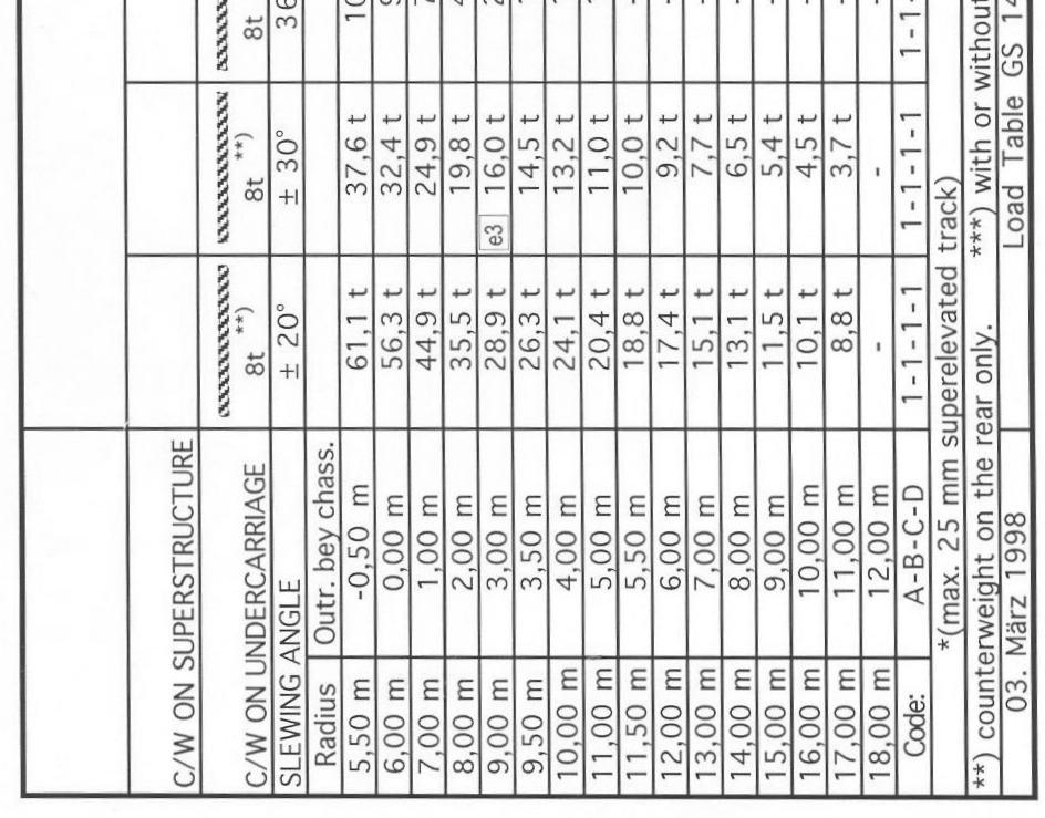
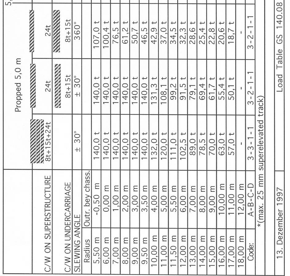
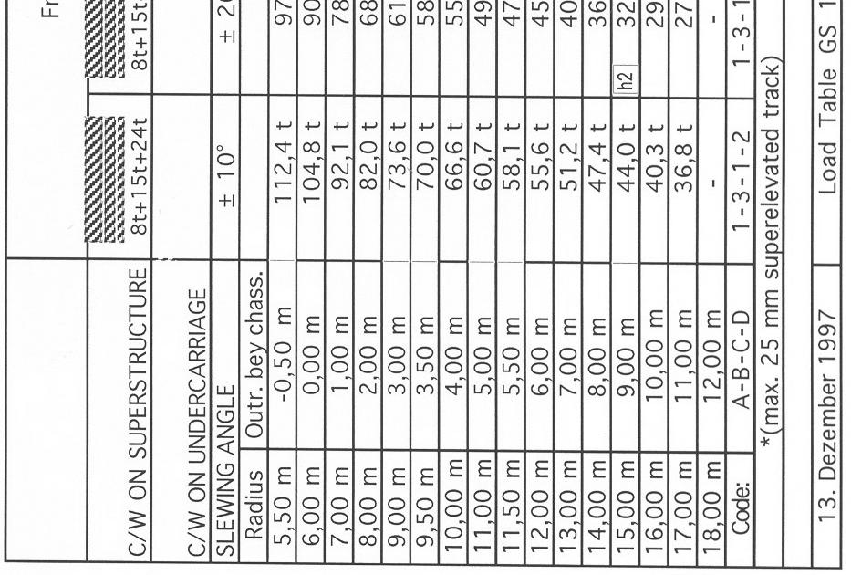
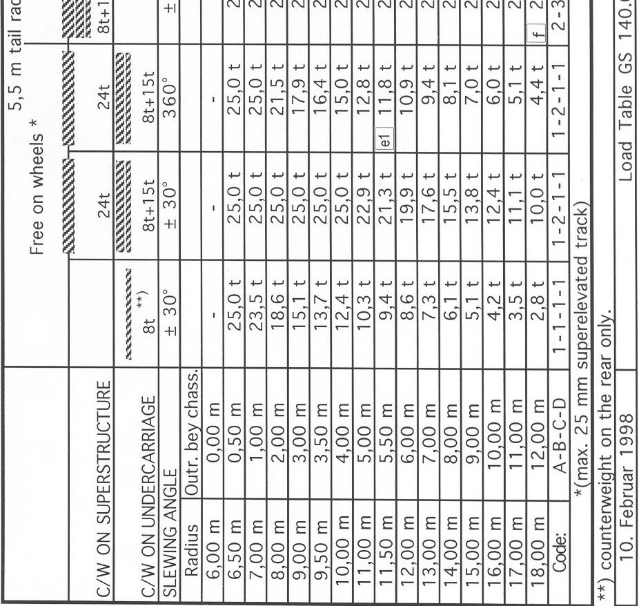
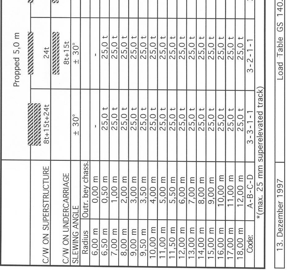
17 Lifting Capacity Chart 3.2 (P-1/1) The lifting capacity charts for each propping base can be found on the next pages. The maximum crane lifting capacity charts are shown in tonnes as a function of the transverse swing - out angle and as a function of the radius beyond buffer in meters. The following outrigger bases as a function of the load are available for work with the crane. Caution: All the data in the lifting capacity as well as the data on the counterweights, working range and hoisting heights must always be observed - Danger of accidents and mortal danger! Remarks on the Lifting Capacity ChartsTechnical DataLifting Capacity Charts Main Hoist 5.5 m counterweight radius: - free - on wheels; - propped at 6.0 m; Main Hoist 5.5 m counterweight radius - propped at 6.0 m and 2.9 m; Main Hoist 6.5 m counterweight radius: - free on- wheels; - propped at 6.0 m; Main Hoist 5.5 m counterweight radius - Free- on wheels, elevated curves at 25 mm. 140 mm; Auxiliary Hoist with retracted main hoist hook block m counterweight radius: - free on- wheels; - propped at 6.0 m; 6.5 m counterweight radius: - free-on wheels; Auxiliary Hoist 5.5 m counterweight radius: - free on wheels; - propped at 6.0 m 6.5 m counterweight radius: - free on wheels, Auxiliary Hoist with retracted main hoist hook block m counterweight radius: - propped at 5.0 m; - propped at 2.9 m; Auxiliary Hoist 5.5 m counterweight radius - propped at 5.0 m; - propped at 2.9 m; Main Hoist m counterweight radius; - free on wheels; Main Hoist m counterweight radius: - free-- on-- wheels;
 are selected, work is only permitted when the 3 rd")
 in opposite direction to working position otherwise the crane stability will be reduced Danger of accidents!")
18 Special Notations for the Lifting Capacity Charts (P-1/2) Caution! When the lifting capacity charts marked with **) are selected, work is only permitted when the 3 rd counterweight (8t) is lying on the undercarriage (frame mechanism is folded in!) in opposite direction to working position otherwise the crane stability will be reduced Danger of accidents! Figure above: Work when crane propped; Figure below: Work when crane free-on-wheels;
19 Special Notations for the Lifting Capacity Charts (P-2/2) Caution! When the lifting capacity charts marked with ****) are selected, the following must be observed: When the crane carries out work free-on-wheels in elevated curves of 40 mm or higher, the attached loads must be secured against pendulous swinging by means of the recovery winch or an auxiliary rope designed for the loading - as otherwise the standing stability of the crane is endangered - Danger of accidents! This means: As soon as a load is attached in rail line direction and the crane is slewed to the downhill side, the recovery winch rope or an auxiliary rope designed for the loading must prevent the increase in radius which otherwise would occur on the downhill side! (See figure above)

20 Main Hoist (P-1/1)

21 Main Hoist (P-1/1)

22 Main Hoist (P-1/1)
")
23 Main Hoist (P- 1/1)


24 Auxiliary Hoist with Retracted Main Hoist Block (P-1/1)

25 Auxiliary Hoist (P-1/1)


26 Auxiliary Hoist (P-1/1)

27 Auxiliary Hoist (P-1/1)

28 Main Hoist (P-1/1)
")
29 Main Hoist (P-1/1)
30 General Operating Drawing 3.3 P-1/1
31 Check Lists 4 (P-1/1) 4. Check Lists Note: The points in these check lists are not a replacement for the descriptions, instructions and safety instructions in the! The daily checks laid down in the Maintenance Manual are not included in the following check lists. 4.1 Check Lists for Operation Propped Crane Operation Free-On-Wheel Crane Operation 4.2 Check List for Rigging In Train Formation Out Train Formation
32 4.1 Check List for Operation Propped Crane Operation (p.1/2) Number in the Instructions Operation Check & Safety Instructions Indicator Raise boom Match truck is uncoupled Engage travel gear Check main hoist & auxiliary hoist ropes Check luffing gear rope Check recovery winch rope Perform diesel engine check Perform visual control of hydraulics Switch main battery switch to ON Move all control levers to neutral position Start diesel engine Safe load indicator switches on automatically Regulate accelerator Check air pressure (min, 5 bar) Pressure gauge in cab If required, release parking brake and remove drag shoes Set hydraulics selector switch to undercarriage Enter code for rigging ( ) Safe load indicator Extend outrigger beams to selected position Extend jack cylinders Select propping base Safe load indicator Set hydraulics selector switch to counterweight hydraulics If required, pick up counterweight Select counterweight combination Safe load indicator If required, increase / decrease counterweight radius Select 5.5 m or 6.5 m counterweight radius Set hydraulics selector switch to crane operation Retract main hoist hook block to boom Safe load indicator Notes
33 4.1 Check List for Operation Propped Crane Operation (p.2/2) Number in the Instructions Operation Check & Safety Instructions Indicator Select main hoist hook position Safe load indicator If required, attach lifting gear 5.6.3/4 Raise / lower hoist rope Safe load indicator Slew right/ left Safe load indicator Derrick in and out boom Safe load indicator Move all control levers to neutral position On completion of work, observe section Parking Crane Safely Notes
34 4.1 Check List for Operation Free-On-Wheel Crane operation (p.1/2) Number in the Instructions Operation Check & Safety Instructions Indicator Raise boom Uncouple match truck Engage travel gear Check main hoist & auxiliary hoist ropes Check derricking rope Check recovery winch rope Perform diesel engine check Perform visual control of hydraulics Switch main battery switch to ON Move all control levers to neutral position Start diesel engine Safe load indicator switches on automatically Regulate accelerator Check air pressure (min. 5 bar) Pressure gauge in cab If required, release parking brake and remove drag shoes Set hydraulics selector switch to counterweight Enter code for rigging ( ) If required, pick up counterweight Select counterweight combination Safe load indicator If required, increase /decrease counterweight radius Select 5.5 m or 6.5 m counterweight radius Safe load indicator Set hydraulics selector switch to crane operation Retract main hoist hook block to boom Safe load indicator Select main hoist hook block position If required, attach lifting gear 5.6.3/4 Raise / lower hoist rope Safe load indicator Slew right / left Safe load indicator Notes
35 4.1 Check List for Operation Free-On-Wheel Crane Operation (p.2/2) Number in the Instructions Operation Check & Safety Instructions Indicator Derrick in and out boom Safe load indicator Move all control levers to neutral position On completion of work, observe section Parking Crane Safely Notes
36 4.2 Check List for Rigging In Train Formation (p.1/3) Number in the Instructions Operation Check & Safety Instructions Indicator Perform diesel engine check Perform hydraulic system check Engage travel gear undercarriage Check main hoist & auxiliary hoist ropes Check derricking gear and recovery winch ropes Coil recovery winch rope Switch battery main switch to ON Move all control levers to neutral position Set hydraulics selector switch to crane operation Start diesel engine Safe load indicator switches on automatically Regulate accelerator Check air pressure (min. 5 bar) Pressure gauge in cab If required, release parking brake undercarriage Set hydraulics selector switch to undercarriage Hydraulics If required, retract outriggers undercarriage Select propping base 1 Safe load Indicator Approach match truck Couple match truck Move counterweight to match truck side Set hydraulics selector switch to crane operation If required, release main hoist hook block from boom Select main hoist hook block position 1 (freely suspended) Set hydraulics selector switch to counterweight hydraulics Lower boom onto frame mechanism Boom is in straightahead position Safe load Indicator Notes
37 4.2 Check List for Rigging In Train Formation (p.2/3) Number in the Instructions Operation Check & Safety Instructions Indicator Extend counterweight support completely (to resting position) Select counterweight radius 1 (6.5m) Safe load Indicator Select counterweight configuration 1- (without c/w) Safe load Indicator Set hydraulics selector switch to crane operation Rotate superstructure Derrick in further, bridge limit switch for rigging (5.1.11) Ram shorn is located above counterweight support Picking up entire counterweight and raise somewhat Fold in frame mechanism Lower entire counterweight onto undercarriage centering device Release connection between counterweights 2 & Derrick out until counterweights 1 & 2 are above match truck Set down counterweights 1 & 2 onto match truck, release connection Store counterweight 1 on match truck as per regulations Counterweight 3 remains on undercarriage ahead of the cab Lower boom until hook is vertical to the storage place on match truck Lower auxiliary hoist hook Set down auxiliary hoist hook on undercarriage and secure Lower main hoist hook Set down main hoist hook on undercarriage and secure Lower boom further, bridge limit switch for rigging (5.1.11) 5.6.3/4 Simultaneously slacken main & auxiliary hoist rope Insert rope retainer bar Lower boom to boom support 5.6.3/4 Simultaneously slacken main & auxiliary hoist ropes Boom in steepest working position Notes
38 4.2 Check List for Rigging In Train Formation (p.3/3) Number in the Instructions Operation Check & Safety Instructions Move the boom out of its fulcrum point Watch ropes! Simultaneously slacking derricking rope (derrick out) Thus, boom head slips into boom support guide Locked! If required, move superstructure in 0 position Set hydraulics selector switch to counterweight hydraulics Lower counterweight support/lower superstructure Watch ropes! Simultaneously unlock c/w support locking device Simultaneously slacken derricking rope (derrick out) Set hydraulics selector switch to undercarriage Indicator Dismantle the outrigger pads and store on match truck as per regulations Retract the jack cylinders completely Retract outrigger beams and secure Select free-on-wheel propping base 1- Safe load indicator Switch on parking brake Disengage travel gear Undercarriage Shut down crane Close windows and doors Remove key and take away Notes It is assumed hat the ambient conditions under which the crane and match truck are parked correspond to local regulations.
39 4.2 Check List for Rigging Out Train Formation (p.1/2) Number in the Instructions Operation Check & Safety Instructions Indicator Perform diesel engine check Perform visual control of hydraulics Check main hoist & auxiliary hoist ropes Check derricking gear & recovery winch ropes Switch battery main switch to ON Move all control levers to neutral position Start diesel engine Safe load indicator switches on automatically Regulate accelerator Check air pressure (min. 5 bar) Pressure gauge in cab Set hydraulics selector switch to undercarriage Enter code for rigging ( ) Safe load indicator Engage travel gear undercarriage If required, release the crane parking brake Set hydraulics selector switch to counterweight hydraulics Raise counterweight support unlock superstructure Watch ropes! Simultaneously tension the ropes Counterweight support locking device must latch in! Set hydraulics selector switch to crane operation Unlock boom head locking device Derrick in ropes Thus, the boom slips into its fulcrum point Boom head is suspended freely above boom support 5.6.3/4 If required, tension main & auxiliary hoist ropes Notes
40 4.2 Check List for Rigging Out Train Formation (p.2/2) Number in the Instructions Operation Check & Safety Instructions Indicator Derrick in until boom in lowest working position Watch ropes! Caution slacken main or auxiliary hoist ropes (lower) Release hook block bracket 5.6.3/4 Raise main or auxiliary hoist Remove rope retainer bar Hook blocks are suspended freely Set hydraulics selector switch to counterweight hydraulics Pick up counterweight Select counterweight combination Safe load indicator Increase/ decrease counterweight radius Select 5.5 m or 6.5 m counterweight radius Safe load indicator Set hydraulics selector switch to crane operation Retract main hoist hook block to boom Select main hoist block position Safe load indicator If required, uncouple match truck Crane is ready for operation Notes
Railway Crane User s Manual Operation (Part-II)
") User s Manual Operation (Part-II) 140 TONNE DIESEL HYDRAULIC B.D.CRANE WITH A FRAME Table of Contents (Part-II) 1 Lifting Capacity Charts P-1/2 1.1 Load Chart without CWT 1.2 Load Chart with Standard CWT
User s Manual Operation (Part-II) 140 TONNE DIESEL HYDRAULIC B.D.CRANE WITH A FRAME Table of Contents (Part-II) 1 Lifting Capacity Charts P-1/2 1.1 Load Chart without CWT 1.2 Load Chart with Standard CWT
Star Swivel-Arm Hoist Installation and Operating Instructions
 Star Swivel-Arm Hoist Installation and Operating Instructions Conveying & Hoisting Solutions P/L ABN 78 6 7. Purpose of Equipment Star Swivel-Arm Hoists are intended for the transport of materials. Star
A POCKET BOOK on DOs and DON Ts for Operation and Maintenance of Jamalpur/Gottwald 140T DH Crane (Old Design)
") For official use only ISO 9001-2000 Certified Organisation A POCKET BOOK on and for Operation and Maintenance of Jamalpur/Gottwald 140T DH Crane (Old Design) CRANE ORGANISATION EASTERN RAILWAY, LOCOMOTIVE
For official use only ISO 9001-2000 Certified Organisation A POCKET BOOK on and for Operation and Maintenance of Jamalpur/Gottwald 140T DH Crane (Old Design) CRANE ORGANISATION EASTERN RAILWAY, LOCOMOTIVE
DEMAG MODEL AC TON CAPACITY
 LIFTING CHARTS - All Terrain Cranes DEMAG MODEL - 100 TON CAPACITY Working Range Main Boom 1 Liing capacities main boom in 39,700 lb 25' 3'' x 23' 360 85% Main Boom () 0 over rear 35.8 52.8 70.2 70.5 82.0
Railway Crane Maintenance Manual
 Diesel Engine System 2.4 2.4.1 Diesel Engine 2.4.1.1 Diesel Engine (Different Types) 2.4.1.2 Diesel Engine (Crane wise list) 2.4.2 Exhaust System 2.4.3 Fuel System 2.4.4 Diesel Engine Accelerator 2.4.5
LIEBHERR MODEL LTM 1150/1-165 TON CAPACITY
 LIFTING CHARTS - All Terrain Cranes LIEBHERR MODEL - 165 TON CAPACITY I. INFORMATION FOR USING THE LOAD CAPACITY TABLES DANGER: The specifications contained in the operating instructions are of vital importance
National N-55. LOAD CHARTS for Use With WRITTEN EXAMINATIONS
 LOAD CHARTS for Use With WRITTEN EXAMINATIONS National N-55 Manitowoc Crane Group, by providing pages of one of its manuals, is not providing a substitute for training on a Manitowoc crane. These pages
RATED CAPACITY PC - D28 TIDD PC25 RATED CAPACITY MANUAL PC - D28 OCTOBER 2013 REV A PC25
 TIDD MANUAL WARNING Do not operate this crane without reading and understanding the information contained in this document. 1 CONTENTS Contents 1. Warnings. Definitions Operations on side slopes 2. Operations.
Technical data Hydraulic lift crane LR 1160
 Technical data Hydraulic lift crane LR 1160 Dimensions Basic machine with undercarriage R 7700 9700 5120 3500 3000 2200 1620 3770 1500 7200 3625 1000 4800 575 8460 1610 6800 6800 1475 R 5900 15175 6600
Technical data Hydraulic lift crane LR 1160
 Technical data Hydraulic lift crane LR 1160 Dimensions Basic machine with undercarriage R 7700 9700 5120 3500 3000 2200 1620 3770 1500 7200 3625 1000 4800 575 8460 1610 6800 6800 1475 R 5900 15175 6600
TADANO ROUGH TERRAIN CRANE : GR-300EX. (Left-hand steering) GENERAL DATA. BOOM 4-section, 9.7 m m
 GENERAL DATA. BOOM 4-section, 9.7 m m") TADANO ROUGH TERRAIN CRANE MODEL : GR-300EX (Left-hand steering) GENERAL DATA CRANE CAPACITY 30,000 kg at 3.0 m BOOM 4-section, 9.7 m - 31.0 m DIMENSION MASS Overall length approx. 11,245 mm Overall width
TADANO ROUGH TERRAIN CRANE MODEL : GR-300EX (Left-hand steering) GENERAL DATA CRANE CAPACITY 30,000 kg at 3.0 m BOOM 4-section, 9.7 m - 31.0 m DIMENSION MASS Overall length approx. 11,245 mm Overall width
Demag AC 650. Key Contents Dimensions Specifications Main boom Main boom extension Fixed fly jib Luffing fly jib Technical description MAIN MENU
 Key Contents Dimensions Specifications Main boom Main boom extension Fixed fly jib Luffing fly jib Technical description Demag AC 0 Mobile cranes in perfection Key Counterweight Liing capacities on outriggers
General Instructions and Inspection Instructions for Crane
 General Instructions General Instructions and Inspection Instructions for Crane Distributed by Ergonomic Partners Sales@ErgonomicPartners.com www.ergonomicpartners.com Tel: 314-884-8884 EN R_(EN)/1 --
TADANO ROUGH TERRAIN CRANE : GR-700EX. (Left-hand steering) G E N E R A L D ATA
 G E N E R A L D ATA") SPEC. SHEET No. GR-7E-1-214/EU-51 DATE June, 21 TADANO ROUGH TERRAIN CRANE MODEL : GR-7EX (Left-hand steering) G E N E R A L D ATA CRANE CAPACITY BOOM 7, kg at 3. m 5-section, 11.5 m 44. m DIMENSION Overall
SPEC. SHEET No. GR-7E-1-214/EU-51 DATE June, 21 TADANO ROUGH TERRAIN CRANE MODEL : GR-7EX (Left-hand steering) G E N E R A L D ATA CRANE CAPACITY BOOM 7, kg at 3. m 5-section, 11.5 m 44. m DIMENSION Overall
www. terex-cranes.com Demag AC 700 AC 700 Most powerful telescopic crane in the world roadable with full main boom
 Demag Most powerful telescopic crane in the world roadable with full main boom Superior boom technology provides exceptional liing capacities Exceptional capacity enhancements due to new Sideways Superli
Product advantages Mobile crane LTM 1030/2
 Product advantages Mobile crane LTM 1030/2 Max. lifting capacity: 35 t at 3 m radius Max. height under hook: 45 m with biparted swing-away jib Max. radius: 40 m with biparted swing-away jib Performance
Instructions for Use Plain Trolley ULK Geared Trolley UHK
 Instructions for Use Plain Trolley Geared Trolley Item no. Load-carrying capacity (payload) Weight Trolley widths *special trolley widths* Device dimensions mm H / W / D Minimum curve radius mm -005 0,5
GMK Product Guide
 GMK5180-1 Product Guide ANSI B30.5 Imperial 85% Features 180 t (210 USt) capacity 64 m (210 ft) six-section main boom 11 m (59.1 ft) swingaway with jib and/or boom inserts. Maximum 34 m (111.6 ft) length
Before equipment use, please read this operation manual carefully. Serial Number: Date Purchased:
 Pushed & Geared Trolleys OPERATION MANUAL This operation manual is intended as an instruction manual for trained personnel who are in charge of installation, maintenance, repair etc. Before equipment use,
PLATFORM WHEEL WELL ACCESS STAND
 PLATFORM WHEEL WELL ACCESS STAND Page 1 Standards WARNING Safety First Tested in general accordance with the applicable requirements of DIN EN 131 2 : 2012 BS EN 131 7 : 2013 ANSI ASC A14.7 20 2011 The
TADANO ROUGH TERRAIN CRANE. (Left-hand steering) GENERAL DATA. BOOM 4-section, 9.7 m m
 GENERAL DATA. BOOM 4-section, 9.7 m m") DATE July, 2004 TADANO ROUGH TERRAIN CRANE MODEL : GR-300EX (Left-hand steering) GENERAL DATA CRANE CAPACITY 30,000 kg at 3.0 m BOOM 4-section, 9.7 m - 31.0 m DIMENSION Overall length approx. 11,245 mm
DATE July, 2004 TADANO ROUGH TERRAIN CRANE MODEL : GR-300EX (Left-hand steering) GENERAL DATA CRANE CAPACITY 30,000 kg at 3.0 m BOOM 4-section, 9.7 m - 31.0 m DIMENSION Overall length approx. 11,245 mm
TADANO ROUGH TERRAIN CRANE : GR-550EX. (Left-hand steering) G E N E R A L D ATA
 G E N E R A L D ATA") DATE June, 21 TADANO ROUGH TERRAIN CRANE MODEL : GR-55EX (Left-hand steering) G E N E R A L D ATA CRANE CAPACITY 55, kg at 3. m BOOM 5-section, 11.1 m - 42.m DIMENSION Overall length Overall width Overall
DATE June, 21 TADANO ROUGH TERRAIN CRANE MODEL : GR-55EX (Left-hand steering) G E N E R A L D ATA CRANE CAPACITY 55, kg at 3. m BOOM 5-section, 11.1 m - 42.m DIMENSION Overall length Overall width Overall
www. terex-cranes.com Demag AC 350 AC 350 Max. load capacity 400 t Sideways Superlift (SSL) for enormous capacity enhancements
 for enormous capacity enhancements") AC 350 Demag AC 350 Max. load capacity 400 t Sideways Superli (SSL) for enormous capacity enhancements Unmatched maximum boom lengths of 413.3 through the combination of main boom and luffing fly jib Most
AC 350 Demag AC 350 Max. load capacity 400 t Sideways Superli (SSL) for enormous capacity enhancements Unmatched maximum boom lengths of 413.3 through the combination of main boom and luffing fly jib Most
DGMS (Tech.) Circular No. 10 Dated Dhanbad the 19 th July, Safe use of mobile Cranes Code of practice
 Circular No. 10 Dated Dhanbad the 19 th July, Safe use of mobile Cranes Code of practice") DGMS (Tech.) Circular No. 10 Dated Dhanbad the 19 th July, 2002. To Owner, Agent and Manager of all Mines. Safe use of mobile Cranes Code of practice A large numbers of mobile cranes are being used for
DGMS (Tech.) Circular No. 10 Dated Dhanbad the 19 th July, 2002. To Owner, Agent and Manager of all Mines. Safe use of mobile Cranes Code of practice A large numbers of mobile cranes are being used for
Chapter 1 Safety and Operation
 Chapter 1 Safety and Operation General The importance of safe operation cannot be over emphasized. Carelessness and neglect on the part of operators, job supervisors and planners, rigging personnel, and
Ground bearing pressure 1.14 kg/cm 2. Main boom (No xx) max. length High reach (1311.xx and 1008.xx) 83 m Luffing jib (No xx) max.
 max. length High reach (1311.xx and 1008.xx) 83 m Luffing jib (No xx) max.") The operating weight includes the basic machine with crawlers, 2 main winches 120 kn and 14 m main boom, consisting of A frame, boom foot (5.5 m), boom head (8.5 m), 32.3 t basic counterweight, 15 t carbody
The operating weight includes the basic machine with crawlers, 2 main winches 120 kn and 14 m main boom, consisting of A frame, boom foot (5.5 m), boom head (8.5 m), 32.3 t basic counterweight, 15 t carbody
SPEC. SHEET No. GR-800E /EU-01 DATE November, 2012 TADANO ROUGH TERRAIN CRANE M ODEL : GR-800EX (Left-hand steering) G E N E R A L D ATA CRANE
 G E N E R A L D ATA CRANE") DATE November, 212 TADANO ROUGH TERRAIN CRANE M ODEL : GR-8EX (Left-hand steering) G E N E R A L D ATA CRANE CAPACITY 8, kg at 3. m BOOM 5-section, 12. m 47. m DIMENSION Overall length approx. 14,375 mm
DATE November, 212 TADANO ROUGH TERRAIN CRANE M ODEL : GR-8EX (Left-hand steering) G E N E R A L D ATA CRANE CAPACITY 8, kg at 3. m BOOM 5-section, 12. m 47. m DIMENSION Overall length approx. 14,375 mm
Kato CR-200 Ri. 20 t All Terrain Crane. Tel: Fax:
 Kato CR-200 Ri 20 t All Terrain Crane 1565 3165 2965 2245 1665 200 200 1575 350 10 1880 5 13. 350 3210 Min: 6500 Max: 28000 Stroke: 21500 1685 6940 3345 2115 3250 8710 Ramp break over : 23゚ When the suspension
C R A N E SPECIFICATIONS MODEL GR-1450EX CAPACITY 145,000 kg at 2.5 m BOOM 6 sections extended by single telescoping cylinder, 13.1m~61.0m, of round b
 TADANO ROUGH TERRAIN CRANE MODEL : GR-1450EX - Hydraulic offset jib model - (Left-hand steering) G E NERAL D ATA CRANE CAPACITY 145,000 kg at 2.5 m BOOM 6-section, 13.1 m 61.0 m DIMENSION MASS Overall
Table of Contents. Boom. Power Jib. Boom. (Stationary on rubber) Boom. (Pick & Carry) Searcher hook. (Option)
 Boom. (Pick & Carry) Searcher hook. (Option)") Boom Power Jib Boom (Stationary on rubber) Boom (Pick & Carry) Searcher hook (Option) Searcher hook (Stationary on rubber)(option) Searcher hook (Pick & Carry)(Option) Table of Contents SPECIFICATION 1
Boom Power Jib Boom (Stationary on rubber) Boom (Pick & Carry) Searcher hook (Option) Searcher hook (Stationary on rubber)(option) Searcher hook (Pick & Carry)(Option) Table of Contents SPECIFICATION 1
Cranes. Range Diagram and Lifting Capacity RT TON LIFTING CAPACITY RANGE DIAGRAM 40' - 126'
 Range Diagram and Lifting Capacity Cranes 80 TON LIFTING CAPACITY RANGE DIAGRAM 40' - 126' BOOM Dimensions are for largest factory furnished hook block and hook & ball, with anti-two block activated COUNTER
HYDRAULIC ROUGH TERRAIN CRANE GENERAL DATA CRANE SPECIFICATIONS SPEC. SHEET NO. GR-300E /EX-41. Left hand steering CRANE CAPACITY
 HYDRAULIC ROUGH TERRAIN CRANE GR-300EX Left hand steering GENERAL DATA CRANE CAPACITY 30,000 kg at 3.0 m BOOM 4-section, 9.7 m - 31.0 m DIMENSION Overall length approx. 11,245 mm Overall width approx.
FULLY HYDRAULIC TRUCK CRANE
 CRANE Description Model Specification Maximum rated lifting capacity length Fly jib length Maximum lifting height Main Hoisting line winch speed Auxiliary winch Main Hoisting winch speed Auxiliary winch
In This Document MODULE DESCRIPTION This module provides information on the safety concerns and
 Crane Safety Fact Sheet In This Document MODULE DESCRIPTION This module provides information on the safety concerns and Introduction necessary precautions you will need to be aware of when working Crane
LOAD CHARTS TMS9000E 85% STABILITY SERIAL NUMBER
 LOAD CHARTS TMS9000E 85% STABILITY SERIAL NUMBER TMS9000E - S/N 1 TMS9000E - S/N 2 CONTENTS GENERAL NOTES...11 WEIGHT REDUCTIONS AND WARNING NOTES... 12 COUNTERWEIGHT CONFIGURATIONS... 13-15 LIFTING AREA
GMK5150 Product Guide
 GMK5150 Product Guide ASME B30.5 Imperial 85% Features 150 t (175 USt) capacity 50,8 m (167 ft) five-section boom 11,2 m (36 ft) / 17,8 m (58 ft) bi-fold swingaway Two 8 m (26 ft) boom extensions and one
CRANE TESTING REQUIREMENTS FOR PERFORMANCE TESTS
 APPENDIX I CRANE TESTING REQUIREMENTS FOR PERFORMANCE TESTS 1. PERFORMANCE TESTING. a. Performance testing includes both operational performance testing and load performance testing. The following tables
PRELIMINARY. Product Guide. Crawler Crane
 SCC8500 Crawler Crane PRELIMINARY 550 U.S. Tons (500 Metric Tons) @ 19.7 ft Radius 364.2 ft Max Tip Height (Main Boom) Main Boom, Fixed Jib and Luffing Jib Configurations Product Guide 2 SCC8500 Power
Hydraulic Crawler Crane
 Hydraulic Crawler Crane Model : BMS1000 Max. Lifting Capacity: 100 t x 3.8 m Max. Crane Boom Length: 62.6 m BMS1000 CONTENTS 3 SPECIFICATIONS 5 6 8 9 10 11 12 13 14 1 GENERAL DIMENSIONS BOOM AND JIB ARRANGEMENTS
TADANO TRUCK CRANE. Provisional Specifications GENERAL DATA. 4-section, 10.5 m 33.0 m
 DATE July, 2006 TADANO TRUCK CRANE MODEL : TL-300E Provisional Specifications GENERAL DATA CRANE CAPACITY 30,000 kg at 3.0 m BOOM 4-section, 10.5 m 33.0 m DIMENSION MASS Overall length approx. 12,670 mm
CRANE SPECIFICATIONS MODEL GR-300 EX CAPACITY 30,000kg at 3.0m BOOM Four section full power partially synchronized telescoping boom of round hexagonal
 DATE August, 2012 TADANO ROUGH TERRAIN CRANE M ODEL : GR-300EX (Left-hand steering) GENERAL DATA CRANE CAPACITY 30,000 kg at 3.0 m BOOM 4-section, 9.7 m - 31.0 m DIMENSION MASS Overall length approx. 11,245
OVERHEAD & GANTRY CRANE / RIGGING
 Overhead & Gantry Crane / Rigging OVERHEAD & GANTRY CRANE / RIGGING Overhead and gantry cranes - 1910.179 Crawler locomotive and truck cranes. - 1910.180 Slings. 1910.184 Cranes, like all pieces of heavy
Range Diagram and Lifting Capacity T Cranes RANGE DIAGRAM BOOM
 Range Diagram and Lifting Capacity T340-1 Cranes RANGE DIAGRAM 30-94 BOOM Dimensions are for largest factory furnished hook block and hook & ball, with anti-two block activated COUNTER WEIGHT BOOM LENGTH
HYDRAULIC CRAWLER CRANE CK2500
 HYDRAULIC CRAWLER CRANE CK2500 WITH OPTIONAL JIB Max. Lifting Capacity: 250 US Tons Max. Boom Length: 300 ft Max. Boom + Jib Length: 250 ft + 100 ft SPECIFICATIONS FOR CK2500 CRAWLER CRANE The Kobelco
Crawler Crane LR
 Crawler Crane LR 1130 EN LR 1002.03 Dimensions Basic machine with undercarriage R 6530 2970 85 6050 3040 1954 1530 3640 1250 6750 7970 3355 1360 1000 6350 440 1345 R 5700 13930 5310 Operating weight The
SAFETY GUIDANCE MATERIAL
 SAFETY GUIDANCE MATERIAL SAFETY OPERATIONS GUIDANCE MONDAY MARCH 23, 2015 This safety resource was written for the scrap industry by the scrap industry and was developed to assist you in making your scrap
View thousands of Crane Specifications on FreeCraneSpecs.com. Technical data Hydraulic lift crane LR 1250
 Technical data Hydraulic lift crane LR 1250 Dimensions Basic machine with undercarriage R 8700 3500 9700 6050 3000 2150 1600 1345 4600 1500 7520 8700 3740 1830 1200 7000 520 R 6200 19200 7600 1200 5800
Puyuan. QUY 50 Crawler Crane Technical Manual
 Puyuan QUY 50 Crawler Crane Technical Manual 5591796 Pictures and technical parameters in sample books may not accord with the delivery goods because of the improvement in design. Please understand and
PAGE 1 OF 5 HEALTH, SAFETY & ENVIRONMENTAL MANUAL PROCEDURE: S360 Overhead Cranes & Lifts Procedure REV 4.0 8/14/2012
 PAGE 1 OF 5 PURPOSE: OVERHEAD CRANES AND LIFTS PROCEDURE The purpose of this procedure is to define the safety and training requirements for use of overhead cranes and lifts. Procedure: Definitions Designated
Product advantages Mobile crane LTM 1160/2
 Product advantages Mobile crane LTM 1160/2 Max. lifting capacity: 160 t at 3 m radius Max. height under hook: 96 m with swing-away jib Max. radius: 74 m with swing-away jib Performance profile of the LTM
Key Highlights Contents Specifications Dimensions Main boom Main boom extension Technical description. Demag AC 40-1 MAIN MENUE
 Key Highlights Contents Specifications Dimensions extension Technical description Demag AC 40-1 Demag AC 40-1 Most compact 3-axle crane in its category Fast on road and excellent manœuvrability off road
ROUGH TERRAIN CRANE SPECIFICATION. Engine. Type. Transmission. Axles. Suspension. Brake system. Steering. Tire size.
 ROUGH TERRAIN CRANE CRANE Specifi cation Maximum lifting capacity 70ton 2.5m length (6 section) Fly jib length 8.3m-13.2m (2 section, offset 7 60 ) Maximum rated lifting height 45.5m () 58.6m (jib) Hoisting
GT-550E. 55 Metric Tons Capacity EURO-2 HYDRAULIC TRUCK CRANE DIMENSION. Spec. sheet No. GT-550E /C-70
 GT-550E 55 Metric Tons Capacity EURO-2 HYDRAULIC TRUCK CRANE DIMENSION TAIL SWING R3650 MIN 2390 2720 2820 MID 4600 REAR AXLE CENTER 290 2110 MAX 0 400 5480 MIN. 11100 - MAX. 42000 3 SIDE REFL 2650 SIDE
QY70K-ⅠTruck Crane Highlights
 QY70K-ⅠTruck Crane Highlights 1. Full dimension flat-head cab for chassis, all covered walking surface, double H-type outriggers and a fifth jack are available, as well as 360 º operation of boom, power
OPERATING INSTRUCTIONS
 Emergency Cord Switch Type PRS Device identification No.: 91.054 033.001, /.101 and /.201 OPERATING INSTRUCTIONS 2 CE Sign and Conformity The device meets the requirements of the valid European and national
Technical data Hydraulic lift crane LR 1300 W
 Technical data Hydraulic lift crane LR 1300 W Dimensions Basic machine with undercarriage 6390 3000 10570 1475 1760 20 5160 3820 8520 9675 520 4260 1700 1200 00 20 7100 520 00 9 R6 8560 20365 Operating
OSH5063EP(PRS3607) Workplace and Work Equipment Hazard. Session 10. Lifting Operation
 Workplace and Work Equipment Hazard. Session 10. Lifting Operation") OSH5063EP(PRS3607) Workplace and Work Equipment Hazard Session 10 Lifting Operation 1 Lifting equipment Lifting equipment covers any equipment used in the process of lifting loads or people and includes
OSH5063EP(PRS3607) Workplace and Work Equipment Hazard Session 10 Lifting Operation 1 Lifting equipment Lifting equipment covers any equipment used in the process of lifting loads or people and includes
Health & Safety Policy and Procedures Manual SECTION 22 CRANE SUSPENDED PERSONNEL PLATFORMS
 SECTION 22 CRANE SUSPENDED PERSONNEL PLATFORMS 1. Scope: This policy and procedure applies to the design, construction testing, use, and maintenance or personnel platforms and hosting of personnel platforms
Cranes. Range Diagram and Lifting Capacity RT TON LIFTING CAPACITY RANGE DIAGRAM 33' - 110' BOOM
 Range Diagram and Lifting Capacity Cranes 55 TON LIFTING CAPACITY RANGE DIAGRAM 33' - 110' BOOM Dimensions are for largest factory furnished hook block and hook & ball, with anti-two block activated COUNTER
LHM 600. Mobile Harbour Crane
 Mobile Harbour Crane LHM 600 Maximum lifting capacity 208 t Maximum outreach 58 m Ship size New Panamax Very Large Bulk Carrier Ultra Large Container Vessel Main Dimensions Heavy Lift Operation Lifting
Humma UV35-25 LOAD CHARTS. Revision 9. A division of Westfield Nominees. Contains the following load charts: Main winch (Standard & Stationary)
") A division of Westfield Nominees Humma UV35-25 Revision 9 Contains the following load charts: Main winch (Standard & Stationary) Sliding hook 1 & 2 Rhino hook Fly-jib www.dragroup.com.au Construct Engineering
A division of Westfield Nominees Humma UV35-25 Revision 9 Contains the following load charts: Main winch (Standard & Stationary) Sliding hook 1 & 2 Rhino hook Fly-jib www.dragroup.com.au Construct Engineering
6. Working radii are measured from centre of swing and under load.
 The operating weight includes the basic machine with crawlers, 2 main winches 120 kn and 20 m main boom, consisting of A frame, boom foot (7 m), boom head (7 m), boom extension (6 m), 60.6 t basic counterweight,
TADANO ROUGH TERRAIN CRANE. (Right-hand steering) GENERAL DATA. 6-section, 5.3 m m
 GENERAL DATA. 6-section, 5.3 m m") DATE February, 2009 TADANO ROUGH TERRAIN CRANE MODEL : GR-120NL (Right-hand steering) GENERAL DATA CRANE CAPACITY BOOM 12,000 kg at 2.0 m 6-section, 5.3 m - 23.8 m DIMENSIONS Overall length approx. 7,540
DATE February, 2009 TADANO ROUGH TERRAIN CRANE MODEL : GR-120NL (Right-hand steering) GENERAL DATA CRANE CAPACITY BOOM 12,000 kg at 2.0 m 6-section, 5.3 m - 23.8 m DIMENSIONS Overall length approx. 7,540
Global Cranes & Machinery, LLC
 Global Cranes & Machinery, LLC 7 Jersey Shore Drive Houston, TX 777 USA Toll Free: (66) 7-97 Tel: + (7) 56- Fax: + (7) 56-5 E-mail: info@globalcranesales.com www.globalcranes.com Contents Vision Creates
Ground bearing pressure 1.08 kg/cm 2. Main boom (No xx) max. length High reach (No xx and 1309.xx)
 max. length High reach (No xx and 1309.xx)") The operating weight includes the basic machine with crawlers, 2 main winches 120 kn and 17 m main boom, consisting of A frame, boom foot (7 m), boom head (10 m), 50.9 t basic counterweight, 20 t carbody
The operating weight includes the basic machine with crawlers, 2 main winches 120 kn and 17 m main boom, consisting of A frame, boom foot (7 m), boom head (10 m), 50.9 t basic counterweight, 20 t carbody
5. For max. wind speed please refer to lift chart in operator s cab or manual.
 The operating weight includes the basic machine with crawlers, 2 main winches 120 kn including wire ropes (260 m and 495 m) and 20 m main boom, consisting of A frame, boom foot (10 m), boom head (7 m),
Mobile Harbour Crane LHM 550. Maximum lifting capacity 154 t Maximum outreach 54 m Ship size New Panamax, Capesize
 Mobile Harbour Crane LHM 550 Maximum lifting capacity 154 t Maximum outreach 54 m Ship size New Panamax, Capesize Main Dimensions Heavy Lift Operation Lifting Capacities Heavy Lift Operation Load Diagram
Cranes. OSHA Office of Training & Education 1
 Cranes OSHA Office of Training & Education 1 Major Causes of Crane Accidents Contact with power lines Overturns Falls Mechanical failures OSHA Office of Training & Education 2 How Do Accidents Occur? Instability
GMK7550 Product Guide
 GMK7550 Product Guide ASME B30.5 Imperial 85% Features 450 t (550 USt) capacity. m (197 ft) five-section boom. 25 m - 79 m (82 ft - 259 ft) lattice luffing jib t (264,500 lb) counterweight with hydraulic
Grove YB Product Guide. Features. ASME B30.5 Imperial 85%, Metric 85%, DIN/ISO. 13,6 t (15 USt) capacity
 capacity") Grove YB5515-2 Product Guide ASME B3.5 Imperial 85%, Metric 85%, DIN/ISO Features 13,6 t (15 USt) capacity 12,5 m (41 ft) three-section, full-power synchronized boom 9,1 t (1 USt) deck carrying capacity
Grove YB5515-2 Product Guide ASME B3.5 Imperial 85%, Metric 85%, DIN/ISO Features 13,6 t (15 USt) capacity 12,5 m (41 ft) three-section, full-power synchronized boom 9,1 t (1 USt) deck carrying capacity
Technical data Hydraulic crawler crane HS 895 HD
 Technical data Hydraulic crawler crane HS 895 HD Dimensions Basic machine with undercarriage R 9760 3650 10000 5480 3675 2445 1810 3950 1610 1700 7945 9360 3975 1720 R 6360 1100 6800 620 17380 Operating
FULLY HYDRAULIC TRUCK CRANE
 FULLY HYDRAULIC TRUCK CRANE CRANE Description Model Specification Maximum rated lifting capacity length Fly jib length Maximum lifting height Hoisting line speed Hoisting hook speed Main winch Truck crane
CRANE & HOIST SAFETY PROGRAM
 CRANE & HOIST SAFETY PROGRAM 1.0 PURPOSE The purpose of the Crane and Hoist Safety Program is to: 1.1 Ensure a safe work environment for employees who operate, maintain, or work around cranes and hoists
Max. lifting capacity: 100 t Max. lifting height: Max. working radius: 60 m
 Telescopic Crawler Crane Max. lifting capacity: 100 t Max. lifting height: 83 m Max. working radius: 60 m Telescopic Crawler Crane Outstanding off-road capabilities and maneuverability 2 A long telescopic
MANUAL FOR OPERATION & MAINTENANCE OF 140 TONNE GOTTWALD CRANE (1986 DESIGN) REVISED EDITION-2002
 REVISED EDITION-2002") MANUAL FOR OPERATION & MAINTENANCE OF 140 TONNE GOTTWALD CRANE (1986 DESIGN) REVISED EDITION-2002 EASTERN RAILWAY LOCOMOTIVE WORKSHOP JAMALPUR ISSUED: - DEC 2002 User s Manual (Part-I) 140 TONNE DIESEL
MANUAL FOR OPERATION & MAINTENANCE OF 140 TONNE GOTTWALD CRANE (1986 DESIGN) REVISED EDITION-2002 EASTERN RAILWAY LOCOMOTIVE WORKSHOP JAMALPUR ISSUED: - DEC 2002 User s Manual (Part-I) 140 TONNE DIESEL
Hydraulic Crawler Crane
 Hydraulic Crawler Crane Model : CKE1350G-2 Max. Lifting Capacity : 150 t x 4.4 m * Max. Lifting Capacity With Luffing Jib: 36.0 t x 12.0 m Max. Crane oom Length : 76.2 m Max. Luffing oom Length: 47.9 m
MODEL : GT-550EX EURO-2
 DATE February, 2007 TADANO TRUCK CRANE MODEL : GT-550EX EURO-2 GENERAL DATA CRANE CAPACITY 55,000 kg at 3.0 m BOOM 5-section, 11.1 m 42.0 m DIMENSION MASS Overall length approx. 13,480 mm Overall width
T 775. truck crane 75 ton capacity. range diagram & lifting capacities. Range Diagram (40' - 126' boom)
") T 7 truck crane ton capacity range diagram & lifting capacities DEFLECTIONS NOT SHOWN 6' - 9" 4' - 8" DIMENSIONS ARE FOR LARGEST FACTORY FURNISHED HOOK BLOCK AND HOOK & BALL, WITH ANTI-TWO BLOCK ACTIVATED
T 7 truck crane ton capacity range diagram & lifting capacities DEFLECTIONS NOT SHOWN 6' - 9" 4' - 8" DIMENSIONS ARE FOR LARGEST FACTORY FURNISHED HOOK BLOCK AND HOOK & BALL, WITH ANTI-TWO BLOCK ACTIVATED
HYDRAULIC TRUCK CRANE
 HYDRAULIC TRUCK CRANE SPEC. SHEET NO. GT-55E-1-12/EX-91 GT-55E CARRIER : TC-4255 GENERAL DATA CRANE CAPACITY 55, kg at 3. m BOOM 5-section, 11.1 m - 42.m DIMENSION Overall length approx. 13,48 mm Overall
1 Clearheart Construction Co., Inc. Mobile Crane - Onshore MOBILE CRANES Cranes and derricks
 Mobile Crane - Onshore MOBILE CRANES Cranes and derricks. - 1926.550 Cranes, like all pieces of heavy equipment, if not properly operated, inspected and maintained have a potential for causing major bodily
Hydraulic lift crane LR 1110 LR
 Hydraulic lift crane LR 111 EN LR 11.2 Concept and characteristics LR 111 Standard Excellent lifting capacities thanks to optimized distribution of forces New cabin with improved and ergonomic operating
HYDRAULIC ROUGH TERRAIN CRANE GENERAL DATA CRANE SPECIFICATIONS SPEC. SHEET NO. GR-500E /EX-02. Left hand steering CRANE CAPACITY
 HYDRAULIC ROUGH TERRAIN CRANE GR-500EX Left hand steering GENERAL DATA CRANE CAPACITY 50,000 kg at m BOOM 4-section, 10.7 m - 34.7 m DIMENSION Overall length approx. 13,055 mm Overall width approx. 2,980
Heavy Duty Engine Cranes
 Heavy Duty Engine Cranes Operating Instructions & Parts Manual Model Number Atd-7484 Atd-7485 (Foldable Legs) Capacity 2 Ton 2 Ton Model Atd-7484 Model Atd-7485 Atd Tools Inc. 160 Enterprise Drive, Wentzville,
Product Information Overspeed governor GB 260
 Product Information GB 260 Copyright as per DIN ISO 16016. Manufactured under licence of C. Haushahn GmbH & Co. I Subject to modification. Published by SLC Sautter Lift Components GmbH & Co. KG Borsigstrasse
Technical data Hydraulic crawler crane HS 8040 HD
 Technical data Hydraulic crawler crane HS 8040 HD Dimensions Basic machine with undercarriage 2860 7350 3000 1700 1060 3300 1200 2340 4610 5460 R = 3900 700 4200 310 4200 990 11240 Operating weight The
Grease Stand MODEL# DF MAINTENANCE AND OPERATION MANUAL. Page 1
 Grease Stand Page 1 WARNING Safety First Standards Tested in general accordance with the applicable requirements of DIN EN 131 2 : 2012 BS EN 131 7 : 2013 ANSI ASC A147 20 2011 The best insurance against
TELESCOPIC BOOM CRAWLER CRANE 30 TON CAPACITY
 TELESCOPIC BOOM CRAWLER CRANE 6010 30 TON CAPACITY OPTIONAL EQUIPMENT ACCESS WALKWAYS VERSATILE. POWERFUL. DEPENDABLE. Tadano Mantis cranes are engineered as VERSATILE, heavy-duty machines. We match massive
Lifting Capacities Telescopic Boom All Terrain Crane ATC ton (118 metric ton) Link Belt
 Link Belt") Lifting Capacities Telescopic Boom All Terrain Crane ATC 3130 130 ton (118 metric ton) Boom and fly capacities for this machine are listed by the following sections: Fully Extended Outriggers Working Range
Lifting Capacities Telescopic Boom All Terrain Crane ATC 3130 130 ton (118 metric ton) Boom and fly capacities for this machine are listed by the following sections: Fully Extended Outriggers Working Range
ROUGH TERRAIN CRANE SPECIFICATION. CARRIER Carrier specification Maximum traveling speed 49km/h Grade ability
 ROUGH TERRAIN CRANE CRANE Description Rough terrain crane with maximum lifting capacity 13 ton Crane specification 5.3 m 13,000kg 1.7 m (Parts of line : 8) 9.04 m 6,000kg 4.0 m (Parts of line : 4) 12.78
LOAD CHART MANUAL FOR RT55 ROUGH TERRAIN CRANE
 Address:Quantang Indust=rial Park, 2nd Yuanda Road, Changsha Economic and Technological Development Zone, Hunan Province, China Postcode: 410131 Website: www.zoomlion.com LOAD CHART MANUAL FOR RT55 ROUGH
ALL TERRAIN CRANE AR-1600M
 ALL TERRAIN CRANE AR AR-1600M JAPANESE SPECIFICATIONS CARRIER MODEL FAUN RTF160-5 SPEC. NO. AR-1600M-1-90101 The "fully automatic luffing jib" and the "luffing jib" are optional equipment. Refer to the
Tire Size 26.5 x 25 5' 5-1/2" (1661) 12' 2-1/4" (3715)
 12' 2-1/4 (3715)") Dimensions 11' 13' 4" (64) TAILSWING 9' " (2997) OVER FENDERS 22' (66) FULL EXT 15' 9" (4801) MID EXT 9' 3-1/2" (2832) RET 9' 9-1/2" (2985) O/R A B C D E F G H 23.5 x 25 5' 4-1/4" (1631) 11' 11-1/2" (36)
Dimensions 11' 13' 4" (64) TAILSWING 9' " (2997) OVER FENDERS 22' (66) FULL EXT 15' 9" (4801) MID EXT 9' 3-1/2" (2832) RET 9' 9-1/2" (2985) O/R A B C D E F G H 23.5 x 25 5' 4-1/4" (1631) 11' 11-1/2" (36)
Table of Contents. Boom. Power Jib. Boom. (Stationary on rubber) Boom. (Pick & Carry) Searcher hook. (Option)
 Boom. (Pick & Carry) Searcher hook. (Option)") Power Jib (Stationary on rubber) (Pick & Carry) Searcher hook (Option) Searcher hook (Stationary on rubber)(option) Searcher hook (Pick & Carry)(Option) Table of Contents SPECIFICATION 1 Notes for the
Power Jib (Stationary on rubber) (Pick & Carry) Searcher hook (Option) Searcher hook (Stationary on rubber)(option) Searcher hook (Pick & Carry)(Option) Table of Contents SPECIFICATION 1 Notes for the
Range Diagram and Lifting Capacity T Cranes. View thousands of Crane Specifications on FreeCraneSpecs.com RANGE DIAGRAM BOOM
 Range Diagram and Lifting Capacity Cranes RANGE DIAGRAM 30-94 BOOM Dimensions are for largest factory furnished hook block and hook & ball, with anti-two block activated COUNTER WEIGHT BOOM LENGTH UPPERSTRUCTURE
ED5800H SPECIFICATION
 SPEC.F5-3713E ED5800H Hydraulic Earth Drilling Rig SPECIFICATION March, 2011 Nagoya, Japan Tel : 81- (52) - 623-3529 Fax: 81- (52) - 623-4349 Due to company policy of continuous development and improvement,
Series 1400A Hydraulic Crane 33 Ton
 Series 1A Hydraulic Crane 33 Ton Load Ratings DANGER AN UNTRAINED OPERATOR SUBJECTS HIMSELF AND OTHERS TO DEATH OR SERIOUS INJURY YOU MUST NOT OPERATE THIS CRANE UNLESS You have been trained in the safe
Crawler Crane LR 1200 LR
 Crawler Crane LR 1200 EN LR 1004.02 Dimensions Basic machine with undercarriage R 8700 3500 9700 6050 3000 2150 1600 4600 1500 7520 8700 3740 1830 1200 7000 520 1345 R 6200 19200 7600 1200 5800 narrow
Series 1400 Hydraulic Crane 33 Ton Load Ratings
 Series 1 Hydraulic Crane 33 Ton Load Ratings! DANGER AN UNTRAINED OPERATOR SUBJECTS HIMSELF AND OTHERS TO DEATH OR SERIOUS INJURY YOU MUST NOT OPERATE THIS CRANE UNLESS You have been trained in the safe
TADANO MODEL TR-300XL-3-30 TON CAPACITY WORKING RANGE CHART. LIFTING CHARTS - Rough Terrain Cranes
 LIFTING CHARTS - Rough Terrain Cranes TADANO MODEL - 30 TON CAPACITY WORKING RANGE CHART NOTE: Boom and jib geometry shown are for unloaded condition and machine standing level on firm supporting surface.
MODERN CRANE. AC 40 City All Terrain Crane 45 t Lifting Capacity. AC 40 City ALL TERRAIN CRANE. - (866)
") All Terrain Crane 45 t Lifting Capacity ALL TERRAIN CRANE Most compact 3-axle crane in its category Fast on the road and exceptionally maneuverable off road Clearance height is just 9.8 ft HIGHLIGHTS Runner
All Terrain Crane 45 t Lifting Capacity ALL TERRAIN CRANE Most compact 3-axle crane in its category Fast on the road and exceptionally maneuverable off road Clearance height is just 9.8 ft HIGHLIGHTS Runner