MINI-MAX SERIES PISTON ELECTRIC PUMP MANUAL
|
|
|
- Barnard Marsh
- 5 years ago
- Views:
Transcription


1 Edition 0-0-rev.0


2 Edition 0-0-rev.0 Use and Maintenance Manual of Original Instructions CTENTS INTRODUCTI SELECTING STAND-BY TIME PUMPING ELEMENTS GENERAL DESCRIPTI SELECTING WORK TIME ORDER INFORMATI MAIN COMPENTS REPLACING THE TIMER SCHEDULED MAINTENANCE IDENTIFYING THE PRODUCT VARYING THE PUMP FROM REMOTE CTROL TO INTERNAL TIMER DISPOSAL PUMP TECHNICAL FEATURES ELECTRIC CNECTIS HANDLING AND TRANSPORT TIMER TECHNICAL FEATURES PUMP ELECTRIC CNECTIS PUMPING ELEMENT MAINTENANCE 7 TIMER POSITI 7 UNPACKAGING, INSTALLATI 7 PRECAUTIS FOR USE 8 SETTING THE FUNCTIS IN THE DIP SWITCH 8 INSTRUCTIS FOR USE 8 CTRAINDICATIS OF USE 9 TIMER FUNCTIS 9 FILLING 9 OVERALL DIMENSIS 0 COMPENTS 0 TROUBLESHOOTING 0 SPARE PARTS INCLUDED PRODUCT WARRANTY DECLARATI OF CFORMITY


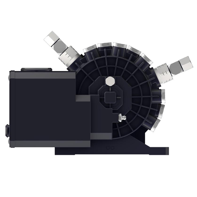
3 Edition 0-0-rev.0. INTRODUCTI This use and maintenance manual refers to the MINI-MAX pump. Using this pump distributes grease in lubrication systems even for high pressures up to 00 bar (,90 psi). You can get the latest version by requesting it from the Technical Sales Office or through our website The pump that is the subject of this manual must be used by qualified personnel with basic hydraulic and electrical knowledge. This use and maintenance manual contains important information to protect the health and safety of personnel who intend to use this equipment. This manual must be read carefully and kept in good conditions so that it is always available to operators who intend to reference it.. GENERAL DESCRIPTI The MINI-MAX electric pump series can be adapted to suit many requirements with no mechanical modifications and even after installation. In fact, you can choose from different components that are perfectly compatible with each other and can be easily installed in order to be able to vary the configuration and the type of distribution. This construction technique is essentially based on the following components: Electric motor - Pump body with integrated reducer - Pumping elements - Tank - Timer The bearing structure is identical in all the versions and always houses at most pumping elements for progressive metering and 8 pumping elements for a single point. The pump body can house two different models of grease tanks Version with spring - presser disk - spatulator and minimum electric level indicator Version with only spatulator and scraper (does not include minimum electric level indicator) The version with presser disk is suitable for use with particularly dense greases, low temperatures, final installation differing from the classic upright positioning or in the event the pump needs to be used on machines whose movement could cause the lubricant to move in the tank and subsequent priming issues. The pump can be checked via the internal programming timer or the control panel of the machine on which it is housed The MINI-MAX electric pump is completely protected from the external environment and can operate with no problem even in harsh environmental conditions. MINI-MAX was designed to supply lubricant systems for use with grease. Using it for purposes other than for what it was intended is considered non-compliant with regulations.. TYPE OF LUBRICATI: WITH PROGRESSIVE METERING - DIRECT TO A POINT MINI-MAX electric pumps can directly lubricate the end point with no need to insert other flow rate metering devices, using the specific pumping elements or via progressive metering to divide the flow rate to the various utilities. You can also pair both individually lubricated points and via progressive metering on the same pump, installing the two different types of pumping elements. This gives you a cost-effective, versatile, easy-to-use product. FEATURES MINI-MAX electric pumps are piston pumps activated by a cam and are able to work with a maximum of 0 pumping elements to supply several lines. If not otherwise specified when ordering, they are standard supplied with a single pumping element for progressive metering. Additional pumping elements must be ordered separately, choosing them based on the desired flow rate from the available models. There are standard versions: the L model has a kg tank and is complete with sensor, presser disk with spring, spatulator and minimum level indicator. The other version differs in its lack of minimum level indicator and, subsequently, presser disk. In this case, in addition to the lower spatulator there is also a blade scraper. The moulded spatulator, located in the pump body at the base of the tank, facilitates lubricant intake and ensures proper operation even at low temperatures. The pump is activated by a or V DC powered gearmotor. An optional control electronic board allows you to set different types of lubrication and cycle, stand-by and check times.. TWO POSSIBLE CTROL CFIGURATIS The product is available in two versions: Control via integrated control circuit Control via machine main panel The model without timer only has an external connection for power and receiving the minimum level signal (if any). Control, stand-by and duration must be managed by the control panel of the machine on which it is applied. The model with integrated timer makes the pump completely independent and you can set WORK TIMES, STAND-BY TIMES (BY TIME OR BY IMPULSES) AND FUNCTI CHECK You can save the stop point so that when the cycle is restarted, it picks up from where it left off (stand-by or lubrication) and enable a cycle every time the machine is started up. MAIN COMPENTS PUMP BODY SPATULATOR PRESSER DISK TANK ELECTRIC CNECTIS PUMPING ELEMENT FOR PROGRESSIVE METERING DEVICES 7 PUMPING ELEMENT FOR SINGLE POINT 8 SINGLE POINT PUMPING ELEMENT CAP 9 O-RING 0 TIMER ACCESS PORTHOLE MOTOR REAR COVER TIMER TIMER

 Degree of protection Minimum level indication Pumping system Max number of outlets/pumping elements Delivery connection (pumping outlet) Metering device pumping")
4 Edition 0-0-rev.0. IDENTIFICAZIE DEL PRODOTTO There is a plate on the back of the pump, which states the product code, the power supply voltage and the basic features.. ELECTRIC PUMP TECHNICAL FEATURES Motor RPM with bar pressure NLGI- grease RPM with 00 bar pressure NLGI- grease. ELECTRIC TIMER TECHNICAL Power supply voltage V V DC 0 rpm at 0 C rpm at 0 C Absorption with 00 bar pressure - C max..8 A at V DC max. 7.A at V DC Initial absorption (0 ms) Degree of protection Minimum level indication Pumping system Max number of outlets/pumping elements Delivery connection (pumping outlet) Metering device pumping element nominal flow rate * ~. A V DC ~8A V DC IP K9K Reed contact A 0 V AC 00 V DC 0 W NA With cam drive and return spring 8 single utilities - progressive metering device supply /8 F single utility pumping elements ¼ metering device pumping elements 0 mm³/rev mm³/rev 0 mm³/rev Pumping element for single point nominal flow rate * mm³/rev mm³/rev 0 mm³/rev Maximum reachable pressure 00 bar Tank capacity Kg Grease consistency Min. NLGI 0 Max. NLGI at real working temperature Operating temperature -0 C +70 C Storage temperature -0 C +0 C Max. relative humidity w/o operating condensate 90% Sound pressure level < 70 db (A) Work positioning Indifferent Power supply voltage V DC - V DC Operating temperature -0 C +70 C Temperatura di stoccaggio -0 C +80 C Selectable working modes Hour-minute-impulse stand-by time - Second-minute work time Pre-lubrication Quick grease dispensing change +/- 0% Accessories Controls Reset manual pushbutton Remote alarm warning Minimum electric level management Progressive metering device cycle control


5 Edition 0-0-rev.0 7. ELECTRIC TIMER POSITI S 0 S 0 8. SETTING THE FUNCTIS IN THE DIP SWITCH OFF The electronic board is located in the pump body near the motor. For any setting operations, time variation or operations, there is no need to remove the closing wall and extract the board. You can access via the side porthole NUMBER FUNCTI STATUS/VALUE PRELUBE NO OFF PRELUBE YES STAND-BY MINUTES OFF STAND-BY HOURS WORK SECDS OFF WORK MINUTES CYCLE CTROL NO OFF CYCLE CTROL YES STAND-BY TIME OFF STAND-BY IMPULSES MIN. ELECTRIC LEVEL NO OFF MIN. ELECTRIC LEVEL YES 9. ELECTRIC TIMER FUNCTIS NUMBER PRELUBE YES PRELUBE OFF NO STAND-BY MINUTES STAND-BY HOURS WORK SECDS WORK MINUTES CYCLE CTROL OFF CYCLE CTROL STAND-BY TIME STAND-BY IMPULSES ELECTRIC LEVEL INDICATOR ELECTRIC LEVEL INDICATOR OFF FUNCTI The PRELUBE condition identifies the function in which at every switch-off and/or power outage, the pump starts with a complete cycle identical to the one set in the selection values The PRELUBE OFF condition identifies the saved work condition. In this case, at every switch-off and/or power outage, the pump picks up again from the stopping point (or stand-by) Identifies the stand-by function with progression in minutes Identifies the stand-by function with progression in hours Identifies the work function with progression in seconds Identifies the work function with progression in minutes the pump works only with stand-by - work time to verify proper lubrication cycle operation, check the inductive microswitch/sensor installed on a progressive divider. If the timer does not receive the signal from the inductive microswitch/sensor during the work cycle, the red LED lights up - the pumps goes into lock and sends a remote alarm signal The stand-by time selects the waiting time between cycles and can be set in progressions (minutes - hours) The stand-by impulses select the function in which a signal sent from the machine is what determines pump cycle start. The minimum electric level check function is active The minimum electric level check function is deactivated
6 Edition 0-0-rev.0 0. COMPENTS Manual pushbutton. Once you have set the desired values, you must press the manual pushbutton for more than in order to save these parameters to the board.. For the reset or extra-cycle function, press the Flashing red LED - the pump does not go into lock Indicates the level pre-alarm, repeats lubrication cycles and at the end, goes into lock Steady red LED - the pump goes into lock. After the cycles from the level pre-alarm. If it does not receive a signal from the microswitch or the inductive sensor installed on the progressive divider Light blue S selector for Setting the stand-by times Red S selector Setting the work times Green LED steady on At start-up for or with the pump in operation. SELECTING THE STAND-BY TIME LIGHT BLUE S SELECTOR STAND-BY VALUE IN MINUTES STAND-BY VALUE IN HOURS STAND-BY VALUE IN IMPULSES STAND-BY VALUE IN IMPULSES A 80 B 8 90 C 0 00 D E F 80 The light blue rotating selector (called S) sets the stand-by time to use. As shown in the table, the selector must be paired with the choice of the progression (hours - minutes - impulses) and whether the stand-by values must be expressed in units of time and/or impulses. Make this selection using the DIP-SWITCH selector LE SELEZII DELLE FUNZII SO INDICATE A PAG.. IN QUESTA TA- BELLA I DATI RIGUARDANO UNICA- MENTE I TEMPI DI PAUSA 0. SELECTING THE WORK TIME RED S SELECTOR WORK VALUE IN SECDS WORK VALUE IN MINUTES The red rotating selector (called S) 0 sets the work time to use. As shown in the table, the selector must be paired with the choice of the progression (seconds minutes). 0 Make this selection 0 using the DIP-SWITCH selector 7 THE FUNCTI SELECTIS ARE 7 8 SHOWN. IN THIS TABLE, THE DATA EXCLUSIVELY REGARD THE 9 0 WORK TIMES A B C 0 D 8 E 0 8 F 0 0


7 Edition 0-0-rev.0. REPLACING THE ELECTRIC TIMER If the timer breaks, you can replace it extremely easily. REMOVE THE SCREWS THE REAR CLOSING COVER EXTRACT THE ELECTRIC TIMER UNHOOK THE EXTERNAL CNECTOR CNECTI CNECTOR UNHOOK THE CNECTI CNECTOR FROM THE INTERNAL SOCKET MAKE THE SAME CNECTIS TO THE NEW TIMER PUT THE TIMER BACK IN, MAKING SURE IT IS INSERTED PROPERLY IN THE GUIDE RAIL POSITI THE CLOSING COVER AND SCREW THE Z SCREWS BACK IN. MODIFYING THE PUMP FROM REMOTE CTROL TO INTERNAL TIMER You can modify MINI-MAX from remote control to internal timer control by ordering the kit (code 9.PWR.7) that includes the timer - -pin alarm connector - 7-pin power supply connector. To perform the operation: OPEN THE REAR COVER UNHOOK THE -PIN SNAP CNECTOR PUT IN THE TIMER REPLACE THE -PIN CNECTOR WITH THE 7-PIN MODEL PUT IN THE M -PIN CIRCULAR CNECTOR CNECT THE INTERNAL TERMINAL BOARD AND THE CNECTORS TO THE BOARD CLOSE THE COVER BACK UP You can also do the operation in reverse order to switch a timer version to remote control. By ordering the kit (code 9.PWR.70) that includes the -pin power supply connector. To perform the operation OPEN THE REAR COVER UNHOOK THE -PIN SNAP CNECTOR REMOVE THE TIMER REPLACE THE 7-PIN CNECTOR WITH THE -PIN MODEL REMOVE THE M -PIN CIRCULAR CNECTOR CNECT THE TERMINAL BOARD TO THE -PIN CNECTOR TERMINAL BOARD CLOSE THE COVER BACK UP 7


.")


8 Edition 0-0-rev.0. ELECTRIC CNECTIS. CABLE ELECTRIC PUMP CNECTI Electric connection is the user s responsibility, who must identify the power supply, min. level alarm and/or cycle alarm connection. Connect the machine to the power line as shown on the pump near the connector. The power cable must have a crosssection that is appropriate for machine absorption and must conform to the provisions in force The MINI-MAX pump is supplied complete with 7-pole electric connector A9.7. The supply includes types of rubbers for different diameters and for unused contacts: no. 7 part no. A9. cables.. mm² no. 7 part no. A9. cables. mm² no. 7 part no. A9.0 cap -WIRE MODEL CODE 7-WIRE MODEL CODE L. MT 0.CBL..0 M L. MT 0.CBL.7.0 M L. 0MT 0.CBL..0 0 M L. 0MT 0.CBL M L. MT 0.CBL.. M L. MT 0.CBL.7. M. CNECTING CTROL ELEMENTS In the version with internal timer, it is possible to manage a cycle control of the progressive metering device (if provided for in the system). In this configuration, a second connector is inserted, to which the cable coming from the -wire cycle control is directed. Connections complete with cables in the different sizes are also available for this configuration Inductive sensors for metering devices DPX Mx PNP-NO Code Mx MODEL CODE L. MT 0.CDC..0 L. 0MT 0.CDC..0 L. MT 0.CDC , Electric scheme 8
9 Edition 0-0-rev.0. PUMP ELECTRIC CNECTI. -CABLE PUMP WITHOUT TIMER CNECTI +() -() 7 = red/black = brown 7. 7-CABLE PUMP WITHOUT TIMER CNECTI +() -() out micro level 7 = red/black = brown = blue = pink The contact between and is closed; when the tank empties, the contact opens. 7 9
 -() N/A N/A NO lamp N/A N/A NC lamp Reset N/A 7 input pulse If we send a (+) to terminal, the working time increases by 0% If we send a (-) terminal, the working")
10 MINI-MAX SERIES ELECTRIC PUMP MANUAL EdItIoN 0-0-rEv.0. PUMP CNECTI WITH TIMER +() -() N/A N/A NO lamp N/A N/A NC lamp Reset N/A 7 input pulse If we send a (+) to terminal, the working time increases by 0% If we send a (-) terminal, the working time decreases by 0% = White = Black = N/A = N/A = N/A = N/A 7 = N/A = brown = blue = black Follow this schematic to connect a proximity switch on the progressive distributor. 0


11 Edition 0-0-rev.0 7. UNPACKAGING AND INSTALLATI 7. UNPACKAGING Once the installation location has been identified, open the packaging, extract the pump and make sure it was not damaged during transport and storage. The packaging material has no special disposal precautions as it is in no way dangerous or polluting. Refer to local regulations for disposal. 7. INSTALLATI Position the electric pump and secure it to its support using the specific securing holes Assemble the pump so that the grease nipple to fill the tank and the timer access porthole are easily accessible Leave a perimeter of at least 00mm with respect to other equipment or obstacles that hinder access to the pump. In the event of filling with a cartridge pump, leave the necessary space Assemble the pump at eye level so as to prevent possible impacts Do not install the pump submerged in liquids and/or in particularly aggressive environments Do not install the pump in environments where there are explosive or inflammable mixtures Do not install the pump near sources of heat or near electrical equipment that may interfere with proper electronic operation Make sure pipes and cables are appropriately secured and protected from impacts Make sure that the lubricant used is suitable for the working temperature, particularly when working with temperatures below 0 C. In case of doubts, contact our Technical Sales Office to choose the right lubricant 7. HYDRAULIC LINE CNECTI The hydraulic connection between the pump and the system occurs at the pumping element delivery seat and must be done with piping and fittings that are suitable for operation with 00 bar pressure. Any unused pumping unit seats can be used as re-entry ports 8. INSTRUCTIS FOR USE 8. WARNINGS The unit can only be commissioned by specialised personnel Using the pump submerged in liquids, in particularly aggressive or explosive/inflammable environments is prohibited unless previously prepared for such purpose by the supplier Use gloves and safety glasses as required by the lubricant safety sheet DO NOT use lubricants that are aggressive for NBR gaskets. In case of doubts, consult our technical office, which will provide information on the recommended lubricants Do not ignore health risks and follow hygiene standards Check the integrity of the pump 8. CHECKS TO PERFORM BEFORE STARTING UP Check the lubricant level in the tank (min/max indication on the tank); in the event of low level, proceed as described in chap. 8 Filling the tank Make sure the pump works at a suitable operating temperature and that there are no air bubbles in the piping Make sure the electrical devices are connected properly Before starting up, it is advisable to fill the piping with grease orusepre-filled piping (if compatible with the grease required for the pump) to simplify the next start-up phase. The lubrication lines must be connected to the pump so that no stress can be transferred to the pump it self (stress-free connection) The fittings used to connect the lubrication lines and the piping it self must be designed for the maximum operating pressure of the system (00 bar) Always use piping that is suitable for the operating pressures 9. FILLING THE TANK MINI-MAX pumps can be filled with standard grease pumps via the specific grease nipple located in the lower part of the pump. It is very important for this operation to be done in a clean environment and for the lubricant going into the tank to have no impurities whatsoever. When filling, do not exceed the maximum lubricant level shown on the tank plate and corresponding to the too-full discharge hole located to the side. The figure shows the standard filling method via a manual and/or pneumatic drum pump that is connected to the grease nipple
")


12 Edition 0-0-rev.0 9. MANUAL FILLING KIT There is a different solution available that is quicker and easy to do that does not require compressed air or grease drums. Commercial cartridge filling pumps can quickly fill the tank, ensuring clean and compact lubricant Remove the progressive metering device pumping element cap and insert the adapter (code ZZZ00-08) Take the pump (code ZZZ00-0) and, after having filled the cartridge, insert it into the adapter seat. Press until all the lubricant comes out. Close the adapter again with its protective cap COD ZZZ00-0 COD. ZZZ RISERVA RESERVE - FINE LOW GRASSO GREASE It is important never to completely empty the lubricant tank. This condition could damage the various parts that require lubrication. In the version equipped with an electric minimum level indicator, use a remote signal to show when the reserve has been reached. In the versions without an electric level, never go below the minimum indicator on the front plate. Should the tank be emptied, after having filled the tank with grease, it is important to run some cycles with the delivery piping disconnected to eliminate the air produced by the pump having operated without grease. Reconnect the piping only after having seen grease with no air bubbles come out 0. TROUBLESHOOTING Below is a diagnostic table containing the main anomalies, the probable causes and the possible solutions to activate immediately. For any doubts and/or irresolvable issues, do not continue troubleshooting by disassembling parts of the pump but rather, contact our technical office 0. ELECTRIC PUMP DIAGNOSTICS TABLE ANOMALY CAUSE SOLUTI TO ADOPT No power Check the power supply system The electronic board does not work Replace the electronic board The pump motor does not work The motor does not work Replace the motor The pump works but lubricant does not reach the final points The pump does not dispense lubricant The pump starts the work phase but stops it immediately Working temperatures too low for the type of grease used Incorrect cycle time setting Unsuitable lubricant used Pumping element intake clogged The pumping element piston is worn Pumping element delivery valve obstructed -dirty Disconnected piping Work temperatures too low for the type of grease used Defective motor or elevated output absorption Replace the lubricant with a suitable model that can be pumped at low temperatures Reprogram the cycle time Empty the tank and refill it with suitable lubricant Disassemble the pumping element and clean the intake conduits Replace the pumping element Clean the delivery valve and, if necessary, replace it Replace the pumping element Replace worn piping Check the condition of the piping and the related connections to the fittings Replace worn piping Replace the lubricant with one that is suitable to be pumped at low temperatures Let it cool down for a few minutes and then try again. If the problem persists, replace the motor 0. TIMER DIAGNOSTICS TABLE ANOMALY CAUSE SOLUTI TO ADOPT No power Check the power supply system The timer does not work Loose or incorrect connections Check the power supply connection in the 7-pole external connector Defective timer Check the connector timer internal connection Replace the timer


13 Edition 0-0-rev.0. PUMPING ELEMENTS. ORDERING CODES MINI-MAX pumping elements are divided into two categories: those used to lubricate single points, featuring very small flow rates and reduced dimensions, and those used to supply progressive metering devices that are, in turn, differentiated by fixed or adjustable flow rates. In addition to having a considerably superior flow rate, they are differentiated by the fact that they have a safety valve that automatically discharges excess pressure over 00 bar. Regardless of the model, the initial fittings must be ordered separately. PUMPING ELEMENTS CODE SINGLE UTILITY FLOW RATE mm³ PER CYCLE PUMPING ELEMENT CODE FIXED METERING DEVICE FLOW RATE MM³ PER CYCLE PUMPING ELEMENT CODE ADJUSTABLE METERING DEVICE FLOW RATE MM³ PER CYCLE INSTALLATI - PUMPING ELEMENT REMOVAL To install a pumping element that was not foreseen when ordering the pump, simply remove the yellow cap from the seat in the position in which you wish to insert the element and screw it all the way in. To ensure proper tightening and gasket seal, the closing force must be Nm Progressive metering device pumping elements Nm Single point pumping elements. ADJUSTABLE PUMPING ELEMENT To vary the nominal pump flow rate, you must loosen the counter nut (Pos. C) and rotate the adjustment screw (Pos. B) clockwise to reduce, or anticlockwise to increase, the amount of lubricant. Once you have set the desired value, it is extremely important to tighten the counter nut again (Pos. C). 0. FLOW RATE ADJUSTMENT TABLE A FLOW RATE/CYCLE PERCENTAGE. 0 mm 00 % CC 7 %. 0.0 CC 0 % CC % CC % CC 0 %


14 Edition 0-0-rev.0. ORDER INFORMATI ASSEMBLY MODEL POSITI FOR METERING DEVICE FOR METERING 7 DEVICE FOR POINT FOR POINT FOR POINT FOR POINT FOR POINT 8 FOR POINT 9 FOR POINT 0 FOR POINT T L. F R. A A B C X X A B IMPORTANT If model, quantity and layout are not specified, MINI-MAX pump is delivered with a single pumping element for metering device installed in pos. No. 7. Additional pumping elements can be ordered separately using the codes shown on the specific table on page. MINI PUMPS ORDERING CODES ASSEMBLY POSITI L aspetto dei prodotti può essere soggetto a modifica senza preavviso VOLTAGE V DC V DC TIMER WITH TIMER T WITHOUT TIMER X ELECTRIC LEVEL WITH LEVEL L WITHOUT LEVEL X SINGLE PUMPING ELEMENTS METERING mm³ METERING 0 mm³ METERING mm³ METERING mm³ METERING 0 mm³ METERING DEVICE PUMPING ELEMENT FIXED ADJUSTABLE NO A B C D E F R X
15 Edition 0-0-rev.0. GENERAL SCHEDULED MAINTENANCE. MAINTENANCE ATTENTI: Before any maintenance or cleaning operations, make sure the hydraulic and electric power supply are disconnected The following tables list the periodic checks, the frequency and the operations that the maintenance technician will have to do to ensure system efficiency over time.the unit is designed and built so as to require minimal servicing. However, remember to CHECK FREQUENCY OPERATI Entire unit 00 hours (depending on the work environment) Always keep the body and the entire structure clean Distribution 000 hours Check piping - fittings and anchoring to the machine Lubricant Depending on system grease consumption Check the level (for pumps without the electric indicator) and the condition of the grease in the tank, paying attention to any unusual decomposition or hardening that would compromise pump and progressive metering device operation Inlet filter Every filling If there is one, check the condition of the internal filtering element. EQUIPMENT The pump does not require any special equipment to check and/or service it. In any case, we recommend using suitable personal protective equipment (gloves, protective glasses, etc.) that is in good condition in accordance with the standards in force to prevent damage to persons or parts of the pump.. LUBRICANTS NOTE: The pump is designed to work with NLGI- maximum grade lubricants at operating temperature. Use lubricants that are compatible with NBR gaskets. Below is a table comparing NLGI (National Lubricating Grease Institute) and ASTM (American Society for Testing and Materials) lubricant classifications, limited to the values concerning MINI-MAX pumps. For further information on the technical features and the safety measures to adopt, refer to the Product Safety Sheet (Directive 9//EEC) regarding the type of lubricant chosen and supplied by the manufacturer.. GREASES NLGI ASTM ATTENTI Do not mix different types of grease. In many cases, this causes damage and requires additional thorough cleaning of all the pump contact parts and any metering devices. We suggest putting an identification plate on the pump that shows the type of lubricant to use to prevent these possible mixes from happening. MINI-MAX pumps are tested with oil and delivered without residues except for slight oiliness, precisely to prevent the above mentioned problems. DISPOSAL When servicing or dismantling the pump, dispose of polluting elements properly, referring to local regulations. When dismantling the pump, the identification plate must be destroyed.. HANDLING AND TRANSPORT Prima della spedizione le pompe sono accuratamente imballate all interno di una scatola di cartone. Durante il trasporto e l immagazzinamento dell apparecchiatura, prestare attenzione al verso indicato sulla scatola. Al ricevimento, controllare che l imballo non sia danneggiato e immagazzinare la pompa in un luogo asciutto.


, spring holder (), gasket () and piston () Thoroughly clean all the parts and the delivery valve seat () Attention: if you")
16 Edition 0-0-rev.0. PUMPING ELEMENT MAINTENANCE In the event of anomalies or every 000 hours, it is a good idea to check the condition of the pumping elements, as they are the heart of the greasing system. Servicing usually involves delivery valve seal which, in the event of wear or impurities, does not work properly and prevents lubricant from being dispensed normally or completely. (see chap. troubleshooting) The operations below can be done without removing the pumping element from the pump body. It is very important for everything to be done in a clean environment by qualified personnel..pumping ELEMENT FOR FIXED FLOW RATE METERING DEVICE. PUMPING ELEMENT FOR ADJUSTABLE FLOW RATE METERING DEVICE Remove the locking screw pos.0 and remove the unit made up by spring (), spring holder (), gasket () and piston () Thoroughly clean all the parts and the delivery valve seat () Attention: if you do not have a spare gasket (), you can rotate it 80 and reassemble it. PUMPING ELEMENT FOR SINGLE PUMP Remove the safety ring pos. 09 and extract the unit made up by the spring pos.0 washer pos.0 gasket pos.0 and piston pos.0. Thoroughly clean the work housing, making sure there is no wear. Check the condition of the gasket pos.0 and replace it, if necessary. If you do not have a spare part, you can rotate it 80 and reassemble it
17 Edition 0-0-rev.0 7. PRECAUTIS FOR USE ATTENTI: You must carefully read the warnings about the risks that come with using a lubricant pump. The user must know how it operates via the Use and Maintenance Manual 7. ELECTRIC POWER SUPPLY 7. INFLAMMABILITY Do not perform any operations on the machine before having disconnected it from the electrical mains and making sure no one can reconnect it during the operation. All the installed equipment (electrical and electronic) must be earthed. The lubricant that is generally used in lubrication circuits is not an inflammable liquid. However, it is fundamental to adopt all the appropriate precautions to prevent it from coming into contact with very hot parts or open flames. 7. PRESSURE 7. NOISE Before every operation, make sure there is no residual pressure in any branch of the lubricant circuit, which could cause oil to spray when disassembling fittings or components. 8. CTRAINDICATIS OF USE Conformity to essential safety requirements and the provisions in the machinery directive was checked by filling out the prepared checklists contained in the technical file. Three types of lists were used: Risk assessment (appendix A of EN 00). Conformity to essential safety requirements (Machinery Directive). Electrical safety provisions (EN 00-). 8. PACCEPTABLE RESIDUAL RISKS Low pressure lubricant may spray out during maintenance. (To this end, maintenance operations must be done using appropriate PPE). Contact with lubricant during maintenance or when filling the tank. The machine user is responsible for providing protection from direct or indirect contact with lubricant. (See provision on the use of suitable means in accordance with the standards in force). Impact and crushing. The moving parts are all contained and the access point has a warning about this hazard. Electric shock. This can only occur in the event of serious incompetence of the user who, for that matter, is qualified. Incongruous postures. The correct overall dimensions and installation methods are shown in this manual. Using unsuitable lubricant. The lubricant features are shown both on the pump and in this manual 8. LIQUIDS THAT ARE NOT ALLOWED LIQUIDS Lubrificants with abrasive additives Lubrificants with silicone additives Petrol solvents inflammable liquids Corrosive products Water Food products HAZARDS High wear of contaminated parts Pump seize Fire - explosion - damaged gaskets Pump corrosion - injury to persons Pump oxidation Contamination of said products 7


18 Edition 0-0-rev.0 9. OVERALL DIMENSIS ,0 7,0 79 8, ,0,0,0,0,0,0,0,0,0,0 8


19 MINI-MAX SERIES PIST ELECTRIC PUMP MANUAL Edition 0-0-rev.0 0. SPARE PARTS SPARE PARTS EXPLODED VIEW POS. ITEM CODe 0 PUMP BODY A8.08 QTY 0 GREASE NIPPLE A /8 CAP A O-RING-07 A TIMER HOLE CAP A x O-RING A9.790 SPARE PARTS EXPLODED VIEW POS. 0 ITEM CODE QTY POS. ITEM CODE MIM A MOTOR BOX COVER A8.087 QTY 0 PUMP BODY A Mx SCREW A Mx0 SCREW UNI9-Mx GASKET A.0 0 COMPASS A SINGLE PUMPING ELEMENT SEAT CAP A REED CTACT A PROG. METERING DEVICE PUMPING UNIT SEAT CAP A9.00 V DC MOTOR A9.00 V DC MOTOR A9.00 SPARE PARTS EXPLODED VIEW NOT AVAILABLE IN THE VERSI WITHOUT ELECTRIC LEVEL INDICATOR POS. 7 ITEM CODE 0 GASKET A89.80 QTY 0 MAGNET A GASKET A x WASHER A ZJ RING A FOLLOWER PLATE A CICAL SPRING A8.8 Not available in the version without electric level indicator 9


20 Edition 0-0-rev.0 SPARE PARTS EXPLODED VIEW SPARE PARTS EXPLODED VIEW 9 POS. ITEM CODE QTY 0 TANK A PLATE A SCREW UNI9-Mx 0 O-RING A SPARE PARTS EXPLODED VIEW OF MODEL WITHOUT ELECTRIC LEVEL INDICATOR POS. ITEM CODE QTY 0 CENTRAL ROD A RS-0 SEEGER UNI7-0 0 x WASHER A.0 0 x7x8 BEARING A RING A9.097 SPATULATOR FOR PUMP A8.089 WITH ELECTRIC MIN. LEVEL INDICATOR 0 SPATULATOR FOR PUMP WITHOUT ELECTRIC MIN. LEVEL INDICATOR 07 CENTRING GRID A GEAR A x0 SCREWS A O-RING A9.79 POS. ITEM CODE QTY 09 x0 SCREWS A9.089 SCRAPER A SCRAPER GASKET A B 0
21 Edition 0-0-rev.0. WARRANTY All ILC products come with a warranty of months from delivery date for construction and material defects. -month extended warranty if the system was installed by ILC. months from the date the commercial components-electrical parts were installed. [if the installation is done after months from the delivery date, the warranty will cover a maximum of 8 months from the delivery date] Should the equipment malfunction, you must notify us of the defect found, providing us the code, the serial number, the delivery and installation dates and the conditions in which the product in question is used. Once we receive this information, at our sole discretion we will decide whether to provide technical assistance direct you to your nearest customer service centre give you a number authorising the return for repair When we receive the equipment and based on accurate analyses, ILC reserves the right to choose whether to repair or replace the product. Should the warranty still be valid, we will see to repairing or replacing the product at our expense. Should the product not be defective, ILC will decide at its discretion whether or not to charge for the sustained costs (logistics). This warranty shall be considered void should the product show damage or cracks due to improper use negligence normal wear chemical corrosion signs of installation that is non-compliant with the explicitly stated instructions and use that is contrary to the manufacturer s recommendations. Modifications, tampering with or alterations to the equipment or parts of it without authorisation from ILC relieve ILC from all liability and from warranty obligations. Parts subject to normal wear and non-durable parts are not covered by the warranty. Anything that is not expressly stated, as well as damage, injury or costs resulting from product defects are to be considered excluded from the warranty. The warranty validity conditions are considered implicitly accepted at the time of purchase. Any varying modifications to this warranty shall only be considered valid upon written authorisation from ILC. ILC declines all liability for damages to persons and things due to failure to observe the requirements in this manual. Any modifications to parts making up the system or using the system or its parts for different purposes without written authorisation from ILC relieves ILC from all liability for damages to persons and/or things and from any warranty obligations.
22 MINI-MAX ELECTRIC PUMP FOR GREASE
MINI-MAX ELECTRIC GREASE PUMP
 MINI-MAX ELECTRIC GREASE PUMP MINI-MAX ELECTRIC GREASE PUMP ECONOMICAL MODULAR The Mini-Max electric pump was designed to work both as a multi-outlet system and with RELIABLE DPX progressive distributors.
PNEUMATIC PUMP Series
 PNEUMATIC PUMP Series 3103... User and Maintenance Manual Original text translation TABLE OF CONTENTS 1. INTRODUCTION 2. GENERAL DESCRIPTION 3. PRODUCT-MACHINE IDENTIFICATION 4. TECHNICAL CHARACTERISTICS
ELECTRIC GREASE AND OIL PUMPS ILC-MAX
 ELECTRIC GREASE AND OIL PUMPS ILC-MAX ELECTRIC GREASE AND OIL PUMPS - ILC-MAX 24 ELECTRIC GREASE (ILC-MAX-G) OIL (ILC-MAX-O) PUMPS HOW TO ORDER 40.2.24AC.FST.G TANK 2 = 2 Kg transparent 4 = 4 Kg transparent
Dragone Pump DROPSA SpA In conformity with section 1.7.4, app. I, EEC Dir. 98/37/CE
 INSTRUCTIONS FOR USE Dragone Pump DROPSA SpA In conformity with section 1.7.4, app. I, EEC Dir. 98/37/CE Company Name DROPSA SpA Address via Croce 1, 20090 Vimodrone (Mi), Italy Model DRAGONE pump Year
Operating Instructions
 Page 1 of 11 CONTENTS 1 PURPOSE... 3 2 APPLICATION... 3 3 DESCRIPTION... 3 4 FUNCTION... 5 5 TECHNICAL PARAMETERS... 5 6 TYPE IDENTIFICATION KEY MMP... 6 7 DIMENSIONAL DRAWING... 7 8 HYDRAULIC DIAGRAM...
Pump Series 999 DROPSA SpA In accordance with point 1.7.4, to I, Dir 98/37 CE
 Pump Series 999 DROPSA SpA In accordance with point.7.4, to I, Dir 98/37 CE INSTRUCTIONS FOR USE Sections: 0.0 INTRODUCTION.0 DESCRIPTION OF THE PUMP.0 TECHNICAL SPECIFICATIONS 3.0 CORRECT USE 4.0 INSTRUCTIONS
MICROPUMP AIR/OIL USE AND MAINTENANCE MANUAL
 MICROPUMP AIR/OIL USE AND MAINTENANCE MANUAL Edition July 2012 Index GENERAL... 3 TECHNICAL CHARACTERISTIC... 3 MINIMUM LEVEL SENSOR... 3 ELECTROVALVE... 3 TYPES... 4 VERSION WITH BOX AND THANK 1.5LT...
CO 3-WAY PNEUMATIC VALVE INSTRUCTION MANUAL 2080
 CO 3-WAY PNEUMATIC VALVE INSTRUCTION MANUAL 2080 STI S.r.l has taken every care in collecting and verifying the documentation contained in this Instruction Manual. The information herein contained are
PoliPUMP. Multi-outlet Grease Pump. User operation and Maintenance manual. Original instructions TABLE OF CONTENTS 1. INTRODUCTION
 PoliPUMP Multi-outlet Grease Pump ITALY Dropsa SpA t. +39 02-250791 f.+39 02-25079767 U.K. Dropsa (UK) Ltd t. +44 (0)1784-431177 f. +44 (0)1784-438598 GERMANY Dropsa GmbH t. +49 (0)211-394-011 f. +49 (0)211-394-013
Mod: KLD6-12/35XLAS-N
 12/2011 Mod: KLD6-12/35XLAS-N Production code: 1914070 INSTRUCTION MANUAL LOGIC LINE PLUS HOOD Reseller Stamp for Warranty Dear customer, Above all, thank you for choosing our product and we would like
lubrication systems PEGPEO 5N-10N-25N-210N pumps for progressive systems
 lubrication systems PEGPEO 5N-10N-25N-210N pumps for progressive systems TABLE OF CONTENTS TABLE OF CONTENTS 2 Applications and operation 3 Technical data Operation 4 Tank 4 PEG-PEO 5N/10N/SM Electric
BELT CONVEYOR CB/M5 Series
 BELT CONVEYOR CB/M5 Series User and maintenance manual 1 DECLARATION OF CONFORMITY The company: Tel. +39-0444 450 620-451 520 Fax +39-0444 671 840 declares under its own responsibility that the machine
Printed: Doc-Nr: PUB / / 000 / 00
 ORIGINAL OPERATING INSTRUCTIONS Hilti HTE-P 33 dispenser It is essential that the operating instructions are read before the tool is operated for the first time. Always keep these operating instructions
SLIDE NEW CONTROL BOARD
 GB SLIDE NEW CONTROL BOARD CN1 CN2 3 4 5 FUSE 2 RL2 RL1 FUSE 1 TR2 TR1 TR3 TR4 U 1 JP1 Ld2 CMR 3 4 CN E Ld7 Ld6 Ld5Ld4Ld3 CN3 3 4 5 6 7 8 9 10 11 SW 12 13 14 Ld1 P2 P1 FUSE 1 FUSE 2 TR1 TR2 TR3 TR4 SW.1
Models CHASSIS LUBE ELECTRIC GREASE PUMP Series "C" - 13C MAY FORM Page. Section - Q3
 Models 94422 CHASSIS LUBE ELECTRIC GREASE PUMP Series "C" MAY - 2004 FORM 403467 Section - Q3 Page - 13C 9.00" (229 mm) 13.75" (350 mm) 0.35" (9mm) Mounting Holes 4.76" (121 mm) 9.84" (250 mm) Do not use
DIAPHRAGM PUMPS: Instruction Manual
 INTRODUCTION DIAPHRAGM PUMPS: Instruction Manual Congratulations for choosing a product Imovilli Pompe, the result of a careful manufacturing process supported by over fifty years of specific experience
Long Chassis Hydraulic Service Jacks
 Long Chassis Hydraulic Service Jacks Operating Instructions & Parts Manual Model Number Atd-7390 Atd-7391 Capacity 5 Ton 10 Ton Atd Tools Inc. 160 Enterprise Drive, Wentzville MO 63385 Printed in China
Models CHASSIS LUBE ELECTRIC GREASE PUMP Series "C" - Q3. MAY FORM Section
 Models 94822 CHASSIS LUBE ELECTRIC GREASE PUMP Series "C" - Q3 MAY - 2004 FORM 403468 Section Page - 14B 13.00" (330 mm) 17.72" (450 mm).35" (9 mm) Mounting Holes 4.72" (120 mm) 9.84" (250 mm) Figure 1
US - UP2/OIL 12V US - UP2/OIL 24V
 SELF PRIMING ELECTRIC PUMP FOR TRANSFERRING LUBRICATING OILS OR VISCOUS FLUIDS INSTRUCTIONS FOR USE 164 220 12-US - UP2/OIL 12V 164 220 13-US - UP2/OIL 24V 15/05/14 Rev.02 A PRODUCT DESCRIPTION Self-priming
VADA - V75-S PRODUCT OVERVIEW CONSTRUCTION USAGE LIMITATIONS MOTOR WARRANTY
 PRODUCT OVERVIEW The VADA V75-S submersible pumps are suitable for installation in traditional wells, water deposits, collection tanks, clear watercourses, lakes etc. The V75-S provides a hydraulic system
INSTRUCTION MANUAL INDUSTRIAL PERISTALTIC PUMPS MODEL RBT-70
 INSTRUCTION MANUAL INDUSTRIAL PERISTALTIC PUMPS MODEL RBT-70 This manual forms an integral part of the pump and must accompany it until its demolition. The series FMP peristaltic pump is a machine destined
User s Manual. Automatic Switch-Mode Battery Charger
 User s Manual Automatic Switch-Mode Battery Charger IMPORTANT Read, understand, and follow these safety rules and operating instructions before using this battery charger. Only authorized and trained service
OFFICINE OROBICHE S.p.A. 1/7 INSTRUCTION MANUAL FOR FLOW SWITCHES PL SERIES
 OFFICINE OROBICHE S.p.A. 1/7 INSTRUCTION MANUAL FOR FLOW SWITCHES PL SERIES 1.INSTRUMENT DESCRIPTION Flow switches PL series are designed to be mounted in an upright position along horizontal pipes. These
240V AdBlue Electric Transfer Pump
 www.scintex.com.au sales@scintex.com.au Model: SAP240V25L 240V AdBlue Electric Transfer Pump User s Manual 1 OF 6 WARNING: Read carefully and understand all INSTRUCTIONS before operating. Failure to follow
Model CHASSIS LUBE ELECTRIC GREASE PUMP Series "C"
 Model 94222 CHASSIS LUBE ELECTRIC GREASE PUMP Series "C" Indicates change MAY - 2004 FORM 403466 Section - Q3 Page - 12B 7.75" (197 mm) 12.6" (321 mm) 0.35" (9 mm) Mounting Holes 4.85" (123 mm) 8.85" (225
FEATURES AND SPECIFICATIONS
 FEATURES AND SPECIFICATIONS The is a high quality hydraulic operator for residential and condominium use with leaf length up to 3 m. Available in the following versions: AC (with lock in opening and closing)
50:1 Grease Pump Kits
 TM INS680A Published: 6/0/00 Revised 7/8/06 50: Grease Pump Kits Models L680A Read the following precautions and instructions before you begin assembly or using. Failure to comply with these instructions
BELT CONVEYOR PNL/4 Series User and maintenance manual
 BELT CONVEYOR PNL/4 Series User and maintenance manual 1 DECLARATION OF CONFORMITY CE In conformity with the 2006/42/CE Machine Directives, Enclosure II, section A The company: VIRGINIO NASTRI S.r.l. Tel.
Sheet n 1 of 20 Doc. n WDMM/02/E MOD. WDMM INSTALLATION, USE AND SERVICE MANUAL. PETROL INSTRUMENTS S.r.l APRILIA (LT) - ITALY
 - ITALY") Sheet n 1 of 20 WATER DRAW/ MASTER METER PETROL COUNTER MOD. WDMM INSTALLATION, USE AND SERVICE MANUAL PETROL INSTRUMENTS S.r.l. - 04011 APRILIA (LT) - ITALY Sheet n 2 of 20 INSTALLATION, USE AND SERVICE
Sheet n 1 of 20 WATER DRAW/ MASTER METER PETROL COUNTER MOD. WDMM INSTALLATION, USE AND SERVICE MANUAL PETROL INSTRUMENTS S.r.l. - 04011 APRILIA (LT) - ITALY Sheet n 2 of 20 INSTALLATION, USE AND SERVICE
EC DECLARATION OF CONFORMITY FOR MACHINES (DIRECTIVE 98/37/EC) WARNINGS FOR THE INSTALLER
 WARNINGS FOR THE INSTALLER") EC DECLARATION OF CONFORMITY FOR MACHINES (DIRECTIVE 98/37/EC) Manufacturer: Address: Declares that: FAAC S.p.A. Via Benini, 1-40069 Zola Predosa BOLOGNA - ITALY 740-24V mod. operator is built to be integrated
EC DECLARATION OF CONFORMITY FOR MACHINES (DIRECTIVE 98/37/EC) Manufacturer: Address: Declares that: FAAC S.p.A. Via Benini, 1-40069 Zola Predosa BOLOGNA - ITALY 740-24V mod. operator is built to be integrated
SMART3 PUMP. User and Maintenance Manual. Original instructions TABLE OF CONTENTS
 SMART3 PUMP ITALY Dropsa SpA t. +39 02-25079 f.+39 02-25079767 UK Dropsa (UK) Ltd t. +44 (0)784-4377 f. +44 (0)784-438598 User and Maintenance Manual Original instructions GERMANY Dropsa GmbH t. +49 (0)2-394-0
Air Operated Double Diaphragm Pump. M-Pump ½ Metallic Non Metallic Pump INSTALLATION, OPERATION & MAINTENANCE MANUAL
 Air Operated Double Diaphragm Pump M-Pump ½ Metallic Non Metallic Pump INSTALLATION, OPERATION & MAINTENANCE MANUAL 0.5 I.O.M rev 05. 12/2015 INDEX Title Section Introduction.1 Safety.2 Warranty, General
Marzocchi Suspension MZ I MZ I. Technical instructions
 Technical instructions Exploded view - MZ I - 100 Rif. Code Quantity Spare part list - MZ I - 100 Rif. Code Description Q.ty in the model Technical characteristics: Technical characteristics Single-crown
UNDERGROUND OPERATOR FOR SWINGING GATES. WARNING!! Before installing, thoroughly read this manual that is an integral part of the pack
 UNDERGROUND OPERATOR FOR SWINGING GATES COMPAS 2 WARNING!! Before installing, thoroughly read this manual that is an integral part of the pack Our products if installed by qualified personnel capable to
US - UP2/E 12/24V
 SELF-PRIMING ELECTRIC PUMP FOR TRANSFERRING VARIOUS LIQUIDS INSTRUCTIONS FOR USE 164 660 15-US - UP2/E 12/24V 14/09/10 Ed.01 AIR VENT VALVE ACTIVATION When starting the pump, or when emptying the tank,
EC DECLARATION OF CONFORMITY
 EC DECLARATION OF CONFORMITY Manufacturer : Address: Declares that: FAAC S.p.A. Via Benini, 1-40069 Zola Predosa BOLOGNA - ITALY 844 T control board, conforms to the essential safety requirements of the
MOUNTING AND CONNECTING INSTRUCTIONS 1. GATE ARRANGEMENT ENGLISH
 SATURN SATURN is a motor reducer designed for the automation of sliding gates with grease lubrication of the gear in the 600 version; in oil bath in the 1000 and 2000 versions. The irreversibility of the
AIR/HYDRAULIC INJECTION GUN MODEL INSTRUCTIONS
 I. OPERATION & DESCRIPTION The Air / Hydraulic Injection Gun is a high-pressure tool that should be used with caution and according to these instructions. IMPORTANT: The Gun is 0,000 psi rated. Do not
Hydronic Corporation
 Hydronic Corporation Air Driven Hydraulic Pumps and Intensifiers P825 Installation, Use and Maintenance Manual Contents Introduction, Guarantee and Identification Plate Description, Start Up Procedures
EC MACHINE DIRECTIVE COMPLIANCE DECLARATION
 EC MACHINE DIRECTIVE COMPLIANCE DECLARATION (DIRECTIVE 89/392 EEC, APPENDIX II, PART B) Manufacturer: FAAC S.p.A. Address: Via Benini, 1 40069 - Zola Predosa BOLOGNA - ITALY Hereby declares that: the 770
SARGON S - M - L. All rights reserved INSTALLATION MANUAL
 INSTALLATION MANUAL Our compliments for your excellent choice. SARGON LINE S (300mm) M (400mm) and L (600mm) electro-mechanical gear motor has been produced for reliability and high quality. This Manual
Features. Marathon SL TECHNICAL CHARACTERISTICS. Sliding bushes: made of friction free and wear free material.
 Features TECHNICAL CHARACTERISTICS Fork with Ø30 mm legs with "Double Air" damping system. Adjustment of the air preload (positive air) on both legs. Adjustment of the rebound damping (negative air) on
Automatic concealed bollards 275 H600 and 275 H800 with pit
 Automatic concealed bollards 275 H600 and 275 H800 with pit Technical installation manual CE Declaration of conformity Warnings for the installer Bollard technical data Preparing and installing the bollard
 VOLUME 3.2 2 This page intentionally left blank JTC 760 Operator s Manual PAGE 3 Table of Contents 1 Summary 1.1 Technical Data 4 1.2 Range of Application 4 1.3 Intended Use 5 1.4 Safety Precaution 5 2
Model 340 Tune-Up Kit Instructions
 Model 340 Tune-Up Kit Instructions Jacobs P/N 019654 tune-up kit instructions Tune-up Kit Contents Illus. No. Jacobs P/N Part Name Quantity Per Kit 4 020229 Upper Seal Ring 3 5 001082 Center Seal Ring
SB ISS.04. Operation Manual AGMDPRO Automatic Spray Gun
 EN SB-2-991 ISS.04 Operation Manual AGMDPRO Automatic Spray Gun Table of Contents Topic Page Specification and Materials of Construction 3 EC Declaration of Conformity 3 Safety Precautions 4 Model Part
240V AdBlue Transfer Pump Stations
 www.scintex.com.au sales@scintex.com.au Model: SPS240VADEF & SPS240VADEFA 240V AdBlue Transfer Pump Stations User s Manual 1 OF 6 WARNING: Read carefully and understand all INSTRUCTIONS before operating.
User Guide. Lubricus Lubrication System LUB-D1/LUB-D2/LUB-D3/LUB-D4 (24 VDC)
") User Guide Lubricus Lubrication System LUB-D1/LUB-D2/LUB-D3/LUB-D4 (24 VDC) version 04/2013 Content General Information 3 Warning 3 Scope of Supply 3 Overview 3 General safety details 4 Intended use 4
User Guide Lubricus Lubrication System LUB-D1/LUB-D2/LUB-D3/LUB-D4 (24 VDC) version 04/2013 Content General Information 3 Warning 3 Scope of Supply 3 Overview 3 General safety details 4 Intended use 4
Pump Operating and Maintenance Manual - Models
 Pump Operating and Maintenance Manual - Models 78-00111 - 78-0057 Thank you for purchasing the SDI Diaphragm Pump manufactured by Comet Pump. Comet produces quality products which are safe, efficient and
EC MACHINE DIRECTIVE COMPLIANCE DECLARATION
 770 EC MACHINE DIRECTIVE COMPLIANCE DECLARATION (DIRECTIVE 89/392 EEC, APPENDIX II, PART B) Manufacturer: FAAC S.p.A. Address: Via Benini, 1 40069 - Zola Predosa BOLOGNA - ITALY Hereby declares that: the
Plunger Heads Use and Maintenance Manual
 Plunger Heads Use and Maintenance Manual UK Positive displacement dosing pump Type PDP Series A-I 175 A-I 250 A-I 350 General instructions We thank you for choosing this product and recommend you read
230V DIESEL FUEL TRANSFER PUMP MODEL NO: DFT230
 230V DIESEL FUEL TRANSFER PUMP MODEL NO: DFT230 PART NO: 7160050 OPERATION & MAINTENANCE INSTRUCTIONS GC0816 INTRODUCTION Thank you for purchasing this CLARKE Pump. The DFTP230 pump is a self-priming rotary
OPERATING MANUAL PHASE SEQUENCE AND MOTOR ROTATION DIRECTION TESTER TKF-13
 OPERATING MANUAL PHASE SEQUENCE AND MOTOR ROTATION DIRECTION TESTER TKF-13 v1.5 07.07.2011 Table of contents 1. Safety measures... 2 2. Phase spin direction test... 3 3. Motor shaft spin direction (using
Oil-free piston compressors KK and piston vacuum pumps KV
 Oil-free piston compressors KK and piston vacuum pumps KV Installation and Operating Instructions 0678106030L02 1707V003 Contents Important information 1 About this document 2 1.1 Warnings and symbols
DulcoFlex Peristaltic Pump: DFB13B
 INSTRUCTION MANUAL DulcoFlex Peristaltic Pump: This manual forms an integral part of the pump and must accompany it until its demolition. The peristaltic pump is a machine destined to work in industrial
What was still missing. Use and maintenance manual. Version n. 3/2015 DUPIGET GREENHOUSE. Code SUPER-B/W (Cleaning and disinfection)
") What was still missing. Use and maintenance manual Version n. 3/2015 DUPIGET GREENHOUSE Code SUPER-B/W (Cleaning and disinfection) Summary A Instructions for safety General information pag. 5 C Instructions
What was still missing. Use and maintenance manual Version n. 3/2015 DUPIGET GREENHOUSE Code SUPER-B/W (Cleaning and disinfection) Summary A Instructions for safety General information pag. 5 C Instructions
IRREVERSIBLE OPERATOR FOR SWING GATES AND DOORS
 VH IRREVERSIBLE OPERATOR FOR SWING GATES AND DOORS WARNING!! Before installing, thoroughly read this manual that is an integral part of the pack Our products if installed by qualified personnel capable
SKF Electro-pneumatic Barrel Pump EPB-Pump-ECO (Original operating and maintenance instructions according to EU Directive 2006/42/EC)
") SKF Electro-pneumatic Barrel Pump EPB-Pump-ECO (Original operating and maintenance instructions according to EU Directive 2006/42/EC) TABLE OF CONTENTS 1 EC Declaration of incorporation...1 2 General description...2
SKF Electro-pneumatic Barrel Pump EPB-Pump-ECO (Original operating and maintenance instructions according to EU Directive 2006/42/EC) TABLE OF CONTENTS 1 EC Declaration of incorporation...1 2 General description...2
Armon Edero. User manual
 User manual Armon Edero Foreword.... 2 Symbols used 2 Intended use.... 2 About the Armon Edero... 2 Mounting options of the Edero 2 Braces. 3 How to set up the Armon Edero.. 3 How to attach the brace to
Instruction, Use and Maintenance Manual CONTROL UNITS J-GIOTTO TOP
 CONTROL UNITS J-GIOTTO TOP Bardiani Valvole S.p.A. via G. di Vittorio, 50/52-43045 Fornovo di Taro (PR) - Italy tel. +39 0525 - Fax 0525 3408 bardiani@bardiani.com - www.bardiani.com MANUAL REVISION DATE
Owner s and Maintenance Manual for: Lincoln QuickLub Systems
 Owner s and Maintenance Manual for: Lincoln QuickLub Systems Contents: I. Introduction 1. System Operation 2. Components II. Pump Mounting and Wiring 1. Power 2. Testing III. Purging and Testing IV. Programming
TECHNICAL MANUAL MT064
 Ed.2005 HEAT EXCHANGERS KSI TECHNICAL MANUAL MT064 INSTALLATION, COMMISSIONING AND MAINTENANCE ISTRUCTIONS TABLE OF CONTENTS 1.0 INTRODUCTION 1.1 MAIN FEATURES 1.2 OPERATION 2.0 ACCESSORIES 2.1 DRAIN VALVES
Operating and Installation Instructions Diaphragm Vacuum Pumps and Compressors
 Operating and Installation Instructions Diaphragm Vacuum Pumps and Compressors Type range: UN813.3ANI UN813.4ANI UN813.3ANDCB UN813.4ANDCB UN813.5ANI Fig. 1: UN813.3ANI Fig. 2: UN813.4ANI You have selected
BELT CONVEYOR CBD/8 Series
 BELT CONVEYOR CBD/8 Series User and maintenance manual 1 DECLARATION OF CONFORMITY CE In conformity with the 2006/42/CE Machine Directives, Enclosure II, section A The company: VIRGINIO NASTRI S.r.l. Tel.
PUR (A, B, C, D) INSTRUCTION FOR VARIABLE SPEED WITH WIRING DIAGRAM FOR EMX P10 ROTOR SIZE
 INSTRUCTION FOR VARIABLE SPEED WITH WIRING DIAGRAM FOR EMX P10 ROTOR SIZE") PUR (A, B, C, D) INSTRUCTI FOR VARIABLE SPEED WITH WIRING DIAGRAM FOR EMX P10 ROTOR SIZE 030 089 2 Installation and commissioning VARIABLE SPEED DESCRIPTI, CTROL CTENTS Safety instructions/scrapping...
PUR (A, B, C, D) INSTRUCTI FOR VARIABLE SPEED WITH WIRING DIAGRAM FOR EMX P10 ROTOR SIZE 030 089 2 Installation and commissioning VARIABLE SPEED DESCRIPTI, CTROL CTENTS Safety instructions/scrapping...
Hydraulic Long Jacks
 Operating Instructions & Parts Manual Hydraulic Long Jacks Model 44915 44930 44940 44980 44981C (Air option) Capacity 1-1/2 Ton 3 Ton 4 Ton 8 Ton 8 Ton Models 44915, 44930, 44940 & 44980 Model 44981C U.S.
US - UP3-R 12V US - UP3-R 24V
 SELF-PRIMING ELECTRIC PUMP FOR TRANSFERRING VARIOUS LIQUIDS INSTRUCTIONS FOR USE 05/0/6 Rev.00 6 008 -US - UP3-R V 6 008 3-US - UP3-R V PRODUCT DESCRIPTION Self-priming electric pump for the transfer of
INSTRUCTION MANUAL FOR PLASMA CUTTER
 INSTRUCTION MANUAL FOR PLASMA CUTTER IMPORTANT: BEFORE STARTING THE EQUIP- MENT, READ THE CONTENTS OF THIS MANUAL, WHICH MUST BE STORED IN A PLACE FAMILIAR TO ALL USERS FOR THE ENTIRE OPERATIVE LIFE-SPAN
IMPORTANT INSTRUCTIONS FOR OPERATION & MAINTENANCE OF
 IMPORTANT INSTRUCTIONS FOR OPERATION & MAINTENANCE OF CONVEYORS EASIKIT 300 EASIKIT 450 EASIKIT 600, 900, 1200 & 1500 The manufacturer does not accept responsibility for any loss, damage to other equipment,
Instruction, Use and Maintenance Manual CONTROL UNITS GIOTTO TOP
 CONTROL UNITS GIOTTO TOP Bardiani Valvole S.p.A. via G. di Vittorio, 50/52-43045 Fornovo di Taro (PR) - Italy tel. +39 0525 - Fax 0525 3408 bardiani@bardiani.com - www.bardiani.com MANUAL REVISION DATE
230V 60Hz LINE FUSES AM CLASS:
 CONTENTS pag. 1. GENERAL 15 2. APPLICATIONS 15 3. PUMPED FLUIDS 15 4. TECHNICAL DATA AND RANGE OF USE 15 5. MANAGEMENT 16 5.1. Storage 16 5.2. Dimensions and weights 16 6. WARNINGS 16 6.1. Skilled personnel
USE and MAINTENANCE INSTRUCTION MANUAL AZ3 HTE2 AZ3 HTE2 HVLP GRAVITY. SPRAY GUN Series. en it fr es pt de se
 USE and MAINTENANCE INSTRUCTION MANUAL AZ3 HTE2 AZ3 HTE2 HVLP GRAVITY SPRAY GUN Series en it fr es pt de se TECHNICAL DATA Technical AZ3 HTE2 AZ3 HTE2 HVLP 1.0 80 180 1.3 10-15HTE 140 200 240 1.5 2.0 160
FITTING AND CONNECTION INSTRUCTIONS
 LEPUS is an oil-bathed motor-reducer created for sliding gates automation. The motor-reducer irreversibility allows a perfect and safe gate closing avoiding the setup of an electrolock and in case of power
Air Actuated Hydraulic Bottle Jack on Wheels
 Operating Instructions & Parts Manual Air Actuated Hydraulic Bottle Jack on Wheels Model Number 18127 18207 Capacity 12 Ton 20 Ton Shinn Fu Co. of America, Inc. 2002 10939 N. Pomona Avenue Kansas City,
Angle seat valve with piston actuator VZXA-...-K
 Angle seat valve with piston actuator VZXA-...-K Festo AG & Co. KG Postfach 73726 Esslingen Germany +49 711 347-0 www.festo.com 3 Further information Accessories www.festo.com/catalogue Spare parts www.festo.com/spareparts
USE AND MAINTENANCE MANUAL. J-Giotto-Top GB-IST-JGIOT-0112
 USE AND MAINTENANCE MANUAL J-Giotto-Top GB-IST-JGIOT-0112 Table of Contents 1. Symbols used...3 2. Safety instructions...3 3. Structure and functions of J-Giotto Top...4 4. Technical data...5 5. Installation...7
MV Series Motors Operation & Parts Manual
 MV Series Motors Operation & Parts Manual Models M3V, M5V, M5V-US For use with M3V s/n 101057 & below, M3V-UK s/n 103013 & below, M5V & M5V-US s/n 102972 & below. EU Declaration of Conformity Finish Thompson
Hydraulic Wheel Dolly
 Hydraulic Wheel Dolly Operating Instructions & Parts Manual Model Number HW93765 Capacity 3/4 Ton Made in the U.S.A. This is the safety alert symbol. It is used to alert you to potential personal injury
OPERATING AND MAINTENANCE INSTRUCTIONS HYDRAULIC ELECTRICAL PUMPS HAM (Manual control) HAE (Electrical control)
 HAE (Electrical control)") OPERATING AND MAINTENANCE INSTRUCTIONS HYDRAULIC ELECTRICAL PUMPS HAM (Manual control) HAE (Electrical control) Part Nr : HA M 4 6 2 1 B C 1. Essential safety requirements. 2. Technical Characteristics.
OPERATING AND MAINTENANCE INSTRUCTIONS HYDRAULIC ELECTRICAL PUMPS HAM (Manual control) HAE (Electrical control) Part Nr : HA M 4 6 2 1 B C 1. Essential safety requirements. 2. Technical Characteristics.
USE AND INSTALLATION HANDBOOK
 Date : 10/02/14 Rev. 01 PR.T : FG006172 USE AND INSTALLATION HANDBOOK DUPLEX-UP CONTROL PANEL FOR 2 ELECTRIC PUMPS WITH CURRENT CONTROL. DUPLEX-UP Via Enrico Fermi 8-35020 Polverara PD Tel.049/9772407
EP1306N 5 Gallon Can Extruder System Rev. A June EP1306N Operation Manual
 EP1306N Operation Manual 1 THIS PAGE HAS BEEN INTENTIONALLY LEFT BLANK 2 TABLE OF CONTENTS SECTION 1: SAFETY... 4 1. GENERAL SAFETY... 5 2. PUMP SAFETY... 5 3. FLUID PRESSURE AND COMPATIBILITY... 6 4.
WELDING INVERTER. PEGAS 160 E Smart PEGAS 200 E Smart OPERATING MANUAL. ALFA IN a.s. PEGAS E Smart Manual EN 04
 WELDING INVERTER PEGAS 160 E Smart PEGAS 200 E Smart OPERATING MANUAL PEGAS 160-200 E Smart Manual EN 04 2/12 CONTENT: 1. INTRODUCTION... 3 2. SAFETY INSTRUCTIONS AND WARNINGS... 4 3. TECHNICAL DATA...
B800 OPERATION MANUAL SPARE PARTS LIST
 B800 OPERATION MANUAL SPARE PARTS LIST BATTERY POWERED PLASTIC STRAPPING TOOL READ ALL INSTRUCTIONS BEFORE OPERATING THE TOOL POLYCHEM CORPORATION 6277 HEISLEY ROAD, MENTOR, OHIO 44060 PHONE: 440.357.1500,
GENERAL WARNING. General instructions. Technical assistance. Doseuro S.r.l. Liability
 Diaphragm interposed fluid head Use and maintenance manual Model Model BR Model UK Positive displacement metering pump PDP Series Type B I 250 I 350 SD GENERAL WARNING General instructions We thank you
POMPE AUTOADESCANTI SELF-PRIMING ELECTRO PUMP ACM DISASSEMBLY AND ASSEMBLY INSTRUCTIONS FOR MULTISTAGE SELF-PRIMING PUMPS
 POMPE AUTOADESCANTI SELF-PRIMING ELECTRO PUMP ACM DISASSEMBLY AND ASSEMBLY INSTRUCTIONS FOR MULTISTAGE SELF-PRIMING PUMPS Ed. 02/2011 5 WARNING These instructions are for the maintenance personnel for
Automatic concealed bollards 275 H600 and 275 H800 Control station
 Automatic concealed bollards 275 H600 and 275 H800 Control station Technical installation manual CE Declaration Warnings for the installer Bollard electrical connection Technical specifications for control
SPECIFICATIONS Horsepower: 1.5 HP Running Maximum PSI: 125 PSI Tank Capacity: 15 Gallons CFM: 6 40 PSI 5 90 PSI
 15 GALLON AIR COMPRESSOR Model: 7678 DO NOT RETURN TO STORE Please call 800-348-5004 for parts and service CALIFORNIA PROPOSITION 65 WARNING: You can create dust when you cut, sand, drill or grind materials
CATALOG. Actuated Diaphragm Valve DN PVC-U / PVC-C / PP-H / PVDF / ABS SMART IN FLOW CONTROL.
 CATALOG Actuated Diaphragm Valve DN 15-100 PVC-U / PVC-C / PP-H / PVDF / ABS SMART IN FLOW CONTROL. TABLE OF CONTENTS Type 186 - DN 12-15 (MA 10) 04 General information - Technical specification 04 Sectional
Automation Swing Gate Opener
 Automation Swing Gate Opener Operating and installation instructions SP EIFFEL 400 V1.0 Rev 08/01 CONTENTS 0) GENERAL SAFETY REGULATIONS...Page 0 1) DESCRIPTION...Page 03 ) TECHNICAL SPECIFICATIONS 3)
EF SERIES MOTORS OPERATION & PARTS MANUAL
 EF SERIES MOTORS OPERATION & PARTS MANUAL Models S1, S2, S3, S4 S1, S2, S3 S4 EU Declaration of Conformity Finish Thompson Inc. hereby declares that the following motors fully comply with the applicable
POWER SUPPLY UNIT FOR 3 KW MAGNETRON TECHNICAL NOTE
 POWER SUPPLY UNIT FOR 3 KW MAGNETRON TECHNICAL NOTE (Issue April 2004) CE Declaration of Conformity Dichiarazione di Conformità CE Manufacturer s Name: Nome del Costruttore: Manufacturer s Address: Indirizzo
HYDRAULIC POWER PACK
 HYDRAULIC POWER PACK OPERATION & MAINTENANCE MANUAL Model 34484 Copyright 2012 by All rights reserved. No part of this publication may be copied, reproduced or transmitted in any form whatsoever without
Air Actuated Hydraulic Bottle Jacks
 Air Actuated Hydraulic Bottle Jacks Operating Instructions & Parts Manual Model Number Atd-7412 Atd-7420 Capacity 12 Ton 20 Ton Atd Tools Inc. 160 Enterprise Drive, Wentzville MO 63385 Printed in China
Operator's Manual. Storage System. Ultrasound Probe Cabinet. Manufactured by:
 Storage System Ultrasound Probe Cabinet Operator's Manual Manufactured by: CIVCO Medical Solutions 102 First Street South Kalona, IA 52247 USA 319.248.6757 / 800.445.6741 WWW.CIVCO.COM Copyright 2018 All
SM825 ver.t Semi-Automatic Car Tire Changer Manual
 SM825 ver.t Semi-Automatic Car Tire Changer Manual REV. 01 1 / 28 PRINTING CHARACTERS AND SYMBOLS Throughout this manual, the following symbols and printing characters are used to facilitate reading: Indicates
INSTALLATION, SERVICE AND MAINTENANCE INSTRUCTIONS Y-FILTER 83700
 INSTALLATION, SERVICE AND MAINTENANCE INSTRUCTIONS Y-FILTER 83700 11.106.32.0001 INOXPA, S.A. c/telers, 54 Aptdo. 174 E-17820 Banyoles Girona (Spain) Tel. : (34) 972-57 52 00 Fax. : (34) 972-57 55 02 email:
INSTALLATION, SERVICE AND MAINTENANCE INSTRUCTIONS Y-FILTER 83700
 INSTALLATION, SERVICE AND MAINTENANCE INSTRUCTIONS Y-FILTER 83700 11.106.32.0001 INOXPA, S.A. c/telers, 54 Aptdo. 174 E-17820 Banyoles Girona (Spain) Tel. : (34) 972-57 52 00 Fax. : (34) 972-57 55 02 email:
TBP SERIES PUMPS OPERATION & PARTS MANUAL
 TBP SERIES PUMPS OPERATION & PARTS MANUAL EU Declaration of Conformity Finish Thompson Inc. hereby declares that the following machine(s) fully comply with the applicable health and safety requirements
READ AND SAVE THESE INSTRUCTIONS. Installation manual. DCC Charge controller for electric vehicle DCC-9, DCC-10. V2-6 Avril 2017.
 READ AND SAVE THESE INSTRUCTIONS Installation manual DCC Charge controller for electric vehicle DCC-9, DCC-10 Manufactured by Designed by V2-6 Avril 2017 Patent Pending Table of contents ABOUT THIS MANUAL
SP6119 / SP6132 OPERATION MANUAL SPARE PARTS LIST
 SP6119 / SP6132 OPERATION MANUAL SPARE PARTS LIST PNEUMATIC SEALER FOR STEEL STRAP WITH SEAL JOINT READ ALL INSTRUCTIONS BEFORE OPERATING THE TOOL POLYCHEM CORPORATION 6277 HEISLEY ROAD, MENTOR, OHIO 44060