OPERATING INSTRUCTIONS
|
|
|
- Dinah Burke
- 6 years ago
- Views:
Transcription


1 Tel: Fax IMIG 180 PORTABLE INVERTER MIG/MAG/MMA WELDER OPERATING INSTRUCTIONS Version
2
3 Thank you for selecting the R-Tech I-MIG180 Portable Inverter MIG/MAG/MMA Welder. The I-MIG180 has many benefits over traditional transformer MIG welders, including infinite power control, adjustable arc force and a durable metal wire feed mechanism to provide very smooth wire feed and weld characteristics We want you to take pride in operating our I-MIG180, as much as we have taken in making this product for you. Please read all information in this manual before operation PLEASE EXAMINE CARTON AND EQUIPMENT FOR DAMAGE IMMEDIATELY When this equipment is shipped, title passes to the purchaser upon receipt from the courier. Consequently all claims for material damaged in shipment must be made by purchaser against the transportation company used. Please record your welding equipment identification below for future reference. This information can be found on data plate at rear of machine. Product I-MIG 180 Serial No. Date of Purchase Where Purchased Whenever you request replacement parts or information on this equipment please supply the information you have recorded above This product is covered by 2 years parts and labour warranty, we will cover cost of collecting and returning item to you (UK mainland only, other areas are RTB). External items, torch, earth lead etc are covered by 3 months warranty. Any faults/damage found caused by customer will be charged pro-rata Please read this operator manual completely before attempting to use this equipment. Pay particular attention to the safety instructions we have provided you for your protection The level of seriousness to be applied to each section is explained below WARNING This statement appears where the information must be followed exactly to avoid serious personal injury. CAUTION This statement appears where the information must be following to avoid a minor personal injury or damage to this equipment.
4 Introduction The R-Tech I-MIG180 is a member of our highly acclaimed family of welding products. Premium features include:- Inverter power source more efficient to operate, provides smoother weld characteristics than traditional welders Infinite welding voltage to allow fine tuning of weld characteristics Euro type torch fittings for easy torch fitment/replacement 35% Duty cycle at C (MIG) 60% Duty cycle at C (MIG) Lightweight and portable Ideal for maintenance and mobile welders Recommended Processes The R-Tech IMIG 180 is recommended for the MIG welding processes within its output capacity of 180 Amps DC (MMA 160Amps) Welding Capability Duty Cycle - Equipment Limitations The R-Tech IMIG 180 is rated at 180 Amps at 35% and % duty cycle on a ten minute basis. If the duty cycle is exceeded a thermal protector will shut the machine off until it cools. Technical Specifications Model No. R-Tech IMIG 180 Input 240V AC 50/60Hz MIG Operation Fuse Rating 16A Rated Output Current 180Amps max Generator required KVA 6 KVA Duty 180 AMPS 40ºC Duty 150 AMPS 40ºC Duty 110 AMPS 40ºC Output current Range AMPS MMA Operation Rated Output Current 160Amps Max Generator required KVA 6 KVA Duty 160 AMPS 40ºC Output current Range AMPS No Load Voltage 75V Gross Weight 16KG Insulation Class F Efficiency η 0.85 Power factor λ=0.8

5 Read entire section before starting installation Safety Precautions WARNING! Electric Shock can kill Only qualified personnel should perform this installation. Turn off input power at the fuse box before working on this equipment. Do not touch electrically live parts. Always connect the machine to an earthed mains supply as per national recommended standards. Select suitable location Place the welder where clean cooling air can freely circulate in and out of the front & rear louver vents. Dirt, dust or any foreign material that can be drawn through vents into welder must be kept to a minimum. Failure to observe these precautions can result in excessive operating temperatures which can lead to plant failure. Grinding Do not direct grinding particles towards the welder. An abundance of conductive material can cause plant failure. Stacking This machine cannot be stacked. Transport Unloading Never underestimate the weight of equipment, never move or leave suspended in the air above people. Use recommended lifting equipment at all times. WARNING! Falling Equipment can cause injury. Never lift welder with gas bottle attached. Never lift above personnel. Tilting Machine must be placed on a secure level surface or on a recommended undercarriage/trolley. This machine may topple over if this procedure is not followed. Environmental Rating The welding power source carries the IP21S rating. It may be used in normal industrial and commercial environments. Avoid using in areas where water / rain is around. Read and follow the Electric Shock Warnings in the safety section if welding must be performed under electrically hazardous conditions such as welding in wet areas or water on the work piece.
6 Electrical Installation WARNING! ELECTRIC SHOCK CAN KILL Machine grounding and High Frequency Interference Protection This welder must be grounded to earth. See national electrical codes fro proper grounding methods. The high frequency generator being similar to a radio transmitter may cause interference to radio, TV and other electronic equipment. These problems may be the result of radiated interference. Proper grounding methods can reduce or eliminate this. Radiated interference can develop in the following ways 1. Direct interference from welder power source 2. Direct interference from the welding leads 3. Direct interference radiated from feedback into power lines 4. Interference from re-radiation by un-grounded metallic objects. Keeping these contributing factors in mind, installing equipment as per following instructions should minimize problems. 1. Keep the welder input power lines as short as possible and enclose as much of them as possible in metal conduit or equivalent shielding. There should be a good electrical contact between this conduit and ground (Earth). 2. Keep the work and electrode leads as short as possible. Tape the leads together where practical. 3. Be sure the torch and earth leads rubber coverings are free from cuts and cracks that allow welding power leakage 4. Keep earth lead connection to work in good condition Clean area on workbench where earth clamp is situated on a regular basis. Input Connections Make sure the voltage, phase and frequency of input power is as specified on machine rating plate located at rear of machine. Have a qualified electrician provide suitable input power as per national electrical codes. Make sure machine is earthed / grounded. Make sure fuse or circuit breaker is correct rating for machine. Using fuses or circuit breakers smaller than recommended will result in nuisance shut off from welder inrush currents even if welding at low amperages. Failure to follow these instructions can cause immediate failure within the welder and void machines warranty.
7 Turn the input power OFF at the mains switch & fuse box before working on this equipment. Have a qualified electrician install & service this MIG welding equipment. Allow machine to sit for 5 minutes minimum to allow the power capacitors to discharge before working inside this equipment. Do not touch electrically live parts The IMIG 180 MIG Welder requires a 240V 50/60Hz 1-Phase 16A supply. It comes with a 2 metre mains cable attached. Connect wires according to national coding. Brown wire Live - Blue wire Neutral - Green/Yellow Wire Earth (Ground) Connecting to an Engine Driven Generator If connecting this machine to an engine driven generator please ensure the following Minimum Generator KVA Output 6 KVA continuous Generator to be fitted with AVR (automatic voltage regulation) DO NOT USE ON A GENERATOR WITHOUT AVR. Connecting to a generator without the above minimum requirements may in-validate your warranty

8 Connections for IMIG 180 Setup machine as per two diagrams below: Fig 1 Fig 2 1. Earth / Workpiece connector. Connect the earth lead (negative -) to this connector. Insert male connector into socket and twist clockwise until tight. Secure other end of earth lead to Workpiece via the earth clamp. 2. Euro torch connector. Connect Euro type MIG torch to euro torch connector, align torch connector to machine connector and then turn retaining ring clockwise to secure. Ensure torch is secured tightly to avoid weld power problems. To avoid electric shock keep the MIG torch in good condition and replace if any of the insulation is damaged. 3. Mains input cable. Fit required plug as per legal requirements. 4. Gas inlet connection. Connect gas hose to rear of machine and then to regulator on gas bottle. Ensure all connections are tight to ensure no loss of gas. Make sure gas bottle is secured to avoid injury as per local health and safety requirements.. 5. On / Off Power Switch. This turns the IMIG 180 MIG Welder on and off. 6, + Power socket:

9 In MMA mode fit electrode holder to this to give positive electrode. For MIG welding with gasless wire, connect earth lead to this socket and change internal polarity cable to negative - For gasless welding torch is negative and earth is + positive Controls and Settings Fig 3 1. Welding Voltage. This adjusts the welding voltage (weld power) from 0 to 10. Adjust knob for power output required by job range is 30 to 180 amps. 2. Wire Speed. This adjusts the wire feed speed from 0-100%. Adjust the wire speed to suit welding voltage (Fig3.1) and job requirements 3. MMA Amps. This adjusts the MMA welding amperage (weld power) from 0 to 10. Adjust knob for power output required by job range is 15 to 160 amps. 4. Mig / MMA switch This switches between the machines two welding modes MIG / MMA 5. OT LED. - If this LED illuminates the duty cycle of machine has been exceeded, the machine will stop working and the fan will continue to run until machine has cooled down. The light will go off and welding may be carried out again. 6. Warning LED. This warning light will come on under these situations to warn of either low input voltage has been sensed or there is an internal fault with machine, check wiring connections, if still illuminated contact R-Tech support department. 7. Power LED. This lights when machine is switched on 8. Spool Gun Switch. When if off position the internal wire feed motor is operational, when switched to on, the internal wire feed motor is disabled and the spool on gun motor will be operational The speed of motors is controlled via the wire feed control knob 2. (Ignore control knob on spool gun as this feature is only used on the MTS255 Digital welder) To fit spool on gun, connect the euro connector to euro socket on front of machine and the separate 7 pin control plug into socket on front of machine.

10 Wire Spool Fitment & Polarity Change (Gasless wire) 1. Wire reel retainer. Screw in to retain wire roll adaptor onto wire reel 2. Roller tensioner. This sets the pressure of rollers, be careful not over tighten wire feed pressure roller as this can cause premature motor and roller failure. Correct way to adjust tensioner is to slacken off pressure so that MIG welding wire does not feed, slowly adjust pressure until wire feeds smoothly, you should be able to stop wire feeding by holding wire and it should slip on rollers. If you have too little pressure wire will slip when welding causing unwanted Burn back into tips or erratic weld beads size. 3. Wire Feed Drive Assembly. Make sure rollers are correct size for wire diameter selected, to change roller size release retaining screw, remove roller turn roller around and slide onto shaft making sure the right size groove is in line with wire and refit retaining screw. The IMIG180 comes fitted with a dual roller 0.6mm and 0.8mm 4. Wire reel adaptor. Remove the wire reel retainer and wire reel adaptor, slide on roll of wire and refit the reel adaptor. 5. Internal negative connector. When using gasless wire, move internal (inside wire feed cabinet) cable to this connector This then makes the torch negative, you would then connect Workpiece earth lead to + positive connector on front of machine (fig 2.1) 6. Internal + positive connector. When using normal welding wire (not gasless), move internal (inside wire feed cabinet) cable to this connector, This then makes the torch positive, you would then connect Workpiece earth lead to - negative connector on front of machine (fig 2.2)


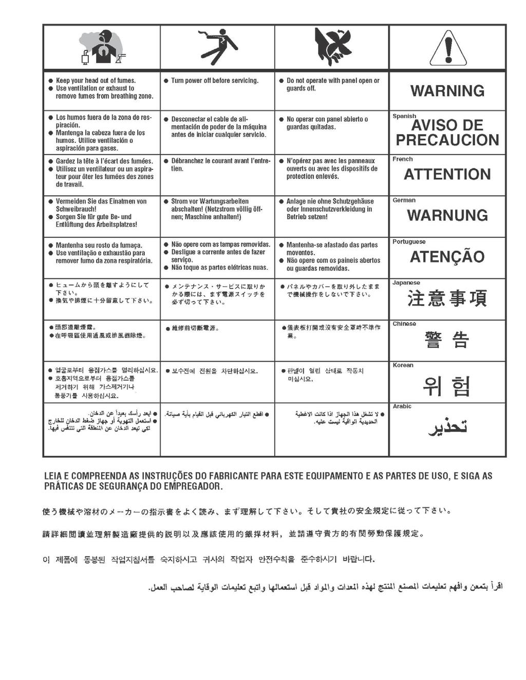
11 Operating the Machine SAFETY PRECAUTIONS WARNING! ELECTRIC SHOCK CAN KILL Do not touch electrically live parts or electrode with skin or wet clothing. Insulate yourself from work and ground Always wear dry insulating gloves WARNING! FUMES AND GASES can be dangerous Keep your head out of fumes & gases produced from welding. Use ventilation or exhaust to remove fumes & gases from breathing zone and general area. WARNING! WELDING SPARKS can cause fire or explosion Keep flammable material away from work area. Do not weld on containers that have held combustibles WARNING! ARC RAYS can burn Wear eye, ear and body protection Make sure work area is protected by proper shielding to avoid injury to passers by.
12 Operating the Machine in MIG mode Once you have set machine up as per above instructions. 1. Select welding voltage (power) required on front panel 2. Select wire feed speed required on wire speed knob 3. Ensure you are wearing the correct safety clothes & equipment for welding (I.E Welding mask, gloves, apron etc) 4. Press torch trigger to start welding process and adjust welding current knob to adjust wire feed accordingly. 5. The LED display will show actual welding amperage when welding (Display will show 000 when not welding) Note: You can finely adjust the welding current knob to fine tune weld arc length to either DIP or SPRAY welding DIP is when the wire is melting very close to the workpiece (Short arc length), SPRAY is when the wire is melting far away from workpiece (Long arc length) 1. Tips on welding aluminium When welding aluminium as the wire is much softer than steel wire you have to fit a Teflon liner in place of the steel liner in MIG torch, this is so the wire feeds much smoother and stops it snarling at rollers. To fit a Teflon liner, remove steel liner from torch and fit Teflon liner so you have about 10 inches left coming out end of MIG torch at the machine end. In the brass euro body where torch fits onto you will see a brass guide tube, remove this tube (you will have to remove circlip to allow this) and fit torch to machine and cut off excess Teflon liner as required. You want the Teflon liner to get as close to the wire feed rollers as possible. Best way to cut liner is with a sharp knife blade. Adjust the wire tensioner to minimum pressure and tighten down until wire is gripped, too much pressure will deform wire and end up with snarls by rollers. The IMIG180 is fitted with rollers suitable for both steel and alloy wire as standard. Fit oversize welding tip. These are available and have and A after tip size. I.E 0.8A where as for steel wire it would just say Tips on using gasless wire When using gasless wire you have to change the polarity of the arc. This can be done simply by reversing the cables inside wire feed cabinet Gas wire = Positive torch Negative work (machine is set as standard) Gasless wire = Negative torch Positive earth
13 R-Tech MIG180 Mig Welder WELDING SETTINGS CARBON STEEL - 0.6MM WIRE DIAMETER INFO JOINT MATERIAL MATERIAL WIRE FILLER GAS VOLTAGE VOLTAGE WIRE SPEED WIRE SPEED POWER SYMBOL TYPE THICKENSS TYPE DIA TYPE TYPE / MIX DIAL SETTING DIAL SETTING AMPS FILLET 1.0 CARBON STEEL 0.6 A18 ARGON +5%CO FILLET 2.0 CARBON STEEL 0.6 A18 ARGON +5%CO FILLET 3.0 CARBON STEEL 0.6 A18 ARGON +5%CO LAP JOINT 1.0 CARBON STEEL 0.6 A18 ARGON +5%CO LAP JOINT 2.0 CARBON STEEL 0.6 A18 ARGON +5%CO LAP JOINT 3.0 CARBON STEEL 0.6 A18 ARGON +5%CO BUTT WELD 1.0 CARBON STEEL 0.6 A18 ARGON +5%CO BUTT WELD 2.0 CARBON STEEL 0.6 A18 ARGON +5%CO BUTT WELD 3.0 CARBON STEEL 0.6 A18 ARGON +5%CO OPEN CORNER 1.0 CARBON STEEL 0.6 A18 ARGON +5%CO OPEN CORNER 2.0 CARBON STEEL 0.6 A18 ARGON +5%CO OPEN CORNER 3.0 CARBON STEEL 0.6 A18 ARGON +5%CO
14 R-Tech MIG180 Mig Welder WELDING SETTINGS CARBON STEEL - 0.8MM WIRE DIAMETER INFO JOINT MATERIAL MATERIAL WIRE FILLER GAS VOLTAGE VOLTAGE WIRE SPEED WIRE SPEED POWER SYMBOL TYPE THICKENSS TYPE DIA TYPE TYPE / MIX DIAL SETTING DIAL SETTING AMPS FILLET 1.0 CARBON STEEL 0.8 A18 ARGON +5%CO FILLET 2.0 CARBON STEEL 0.8 A18 ARGON +5%CO FILLET 3.0 CARBON STEEL 0.8 A18 ARGON +5%CO FILLET 4.0 CARBON STEEL 0.8 A18 ARGON +5%CO FILLET 5.0 CARBON STEEL 0.8 A18 ARGON +5%CO FILLET 6.0 CARBON STEEL 0.8 A18 ARGON +5%CO LAP JOINT 1.0 CARBON STEEL 0.8 A18 ARGON +5%CO LAP JOINT 2.0 CARBON STEEL 0.8 A18 ARGON +5%CO LAP JOINT 3.0 CARBON STEEL 0.8 A18 ARGON +5%CO LAP JOINT 4.0 CARBON STEEL 0.8 A18 ARGON +5%CO LAP JOINT 5.0 CARBON STEEL 0.8 A18 ARGON +5%CO LAP JOINT 6.0 CARBON STEEL 0.8 A18 ARGON +5%CO BUTT WELD 1.0 CARBON STEEL 0.8 A18 ARGON +5%CO BUTT WELD 2.0 CARBON STEEL 0.8 A18 ARGON +5%CO BUTT WELD 3.0 CARBON STEEL 0.8 A18 ARGON +5%CO BUTT WELD 4.0 CARBON STEEL 0.8 A18 ARGON +5%CO BUTT WELD 5.0 CARBON STEEL 0.8 A18 ARGON +5%CO BUTT WELD 6.0 CARBON STEEL 0.8 A18 ARGON +5%CO OPEN CORNER 1.0 CARBON STEEL 0.8 A18 ARGON +5%CO OPEN CORNER 2.0 CARBON STEEL 0.8 A18 ARGON +5%CO OPEN CORNER 3.0 CARBON STEEL 0.8 A18 ARGON +5%CO OPEN CORNER 4.0 CARBON STEEL 0.8 A18 ARGON +5%CO OPEN CORNER 5.0 CARBON STEEL 0.8 A18 ARGON +5%CO OPEN CORNER 6.0 CARBON STEEL 0.8 A18 ARGON +5%CO
15 Operating the Machine in MMA mode Connect the following: 1. Negative welding power connector Connect the earth cable dinse plug into here and twist to secure 2. Positive welding power connector Connect the electrode holder cable dinse plug into here and twist to secure Most popular rods have a positive welding electrode and negative earth. If you are using special electrodes check the manufacturer s recommendation for correct polarity of welding electrodes and connect as required. 1. Ensure machine is setup as previously stated 2. Fit desired electrode size in electrode holder 3. Switch on machine 4. Set Mig/MMA switch to MMA position 5. Select desired welding power 6. Touch electrode on to workpiece and the arc will start When the machine is switched on, output terminals are always live, take care and do not touch electrode and earth by person at same time, otherwise an electric shock will occur. Maintenance Routine and periodic maintenance WARNING! ELECTRIC SHOCK CAN KILL Turn the input power OFF at the mains switch & fuse box and remove mains plug from socket before working on this equipment. Have a qualified electrician install & service this equipment. Allow machine to sit for 5 minutes minimum after disconnection from mains power to allow the power capacitors to discharge before working inside this equipment. Do not touch electrically live parts 1. Periodically (3-6 months depending on use / environment), remove the side/top panels of machine and clean out machine with a low pressure dry air line paying particular attention to PC Boards, Fan blades and switchgear Failure to maintain plant can void manufacturers warranty. 2. Inspect input and output cables & hoses for fraying and cuts, replace if damaged present 3. Keep the MIG torch and earth cables in good condition 4. Clean the air vents to ensure proper air flow and cooling 5. The fan motor has sealed bearings which requires no maintenance
16 Troubleshooting Service & repair should only be performed by R-Tech welding trained personnel. Unauthorized repairs performed on this equipment may result in danger or injury to the technician and machine operator and will invalidate your warranty. For your safety and to avoid electric shock, please observe all safety notes and precautions detailed throughout this manual The troubleshooting guide is provided to help you locate possible machine malfunctions If fault / problem is not listed below check our Mig Welder Support page on our website: or contact R-Tech by phone. Contact details can be found on our website Output Problems No output - Power light is not lit Check machine on/off switch is in the on position Check Input power to machine Check plug wiring Check mains trip / fuses No output - Fan runs - Power light is lit Check torch connections are secure and torch switch operation, try replacing MIG torch. No output - Power light is lit - Warning light is lit Welding application may have exceeded recommended duty cycle, allow machine to cool down until the warning light goes out. No output Power light is lit Gas at torch tip No wire feed Check wire feed unit protecting fuse on rear of machine, if blown replace with new fuse of same rating, if the fuse blows again contact R-Tech Machine keeps overheating - Warning light is lit on machine Check if fan is running if not contact R-Tech. Check the cooling vents for obstruction, blow out machine with clean dry low pressure air supply. Check for adequate ventilation around machine Porosity in weld No / low gas at torch tip Check gas supply from gas bottle, check flow rate on regulator, check gas hose for restrictions, check for draughts in local area, open doors etc Replace MIG torch it may have gas restriction. Poor weld penetration Check condition of earth lead and clamp and ensure clamp is connection via a clean area on work piece. Check the condition of the MIG torch, try another MIG torch.
17

18
OPERATION INSTRUCTIONS
 www.r-techwelding.co.uk Email: sales@r-techwelding.co.uk Tel: 01452 733933 Fax: 01452 733939 ProArc 175 INVERTER ARC WELDER OPERATION INSTRUCTIONS Version 2017-10 2 3 Thank you for selecting the R-Tech
MMA 160S ARC/MMA WELDER OPERATION INSTRUCTIONS
 www.r-techwelding.co.uk MMA 160S ARC/MMA WELDER OPERATION INSTRUCTIONS 2 Thank you for selecting the R-Tech MMA160S Inverter Arc Welder. The MMA160S has many benefits over traditional Arc welders, including
OPERATION INSTRUCTIONS
 www.r-techwelding.co.uk Tel: 01452 733933 Fax 01452 733939 PLASMA 50HF INVERTER PLASMA CUTTER OPERATION INSTRUCTIONS Version 2014-1 2 Thank you for selecting the R-Tech PLASMA 50HF Inverter Plasma Cutter
OPERATION INSTRUCTIONS
 PLASMA 30DV DUAL VOLTAGE INVERTER PLASMA CUTTER OPERATION INSTRUCTIONS 2 Thank you for selecting the R-Tech Plasma 30DV Inverter Plasma Cutter 3 The Plasma 30DV has many benefits over traditional transformer
OPERATION INSTRUCTIONS
 www.r-techwelding.co.uk email: sales@r-techwelding.co.uk Tel: 01452 733933 Fax 01452 733939 TIG160PDC DC TIG WELDER OPERATION INSTRUCTIONS Version 2014-1 2 Thank you for selecting the R-Tech Tig160PDC
OPERATION INSTRUCTIONS
 TIG200PDC TIG WELDER OPERATION INSTRUCTIONS 2 3 Thank you for selecting the R-Tech Tig200PDC Inverter DC Tig Welder. The Tig200PDC has many benefits over traditional tig welders, including pulse welding,
POWER MTS210D MIG - TIG - MMA WELDING MACHINE OPERATION INSTRUCTIONS
 www.r-techwelding.co.uk email: sales@r-techwelding.co.uk Tel: 01452 733933 Fax 01452 733939 POWER MTS210D MIG - TIG - MMA WELDING MACHINE OPERATION INSTRUCTIONS Version 2014-1 2 Thank you for selecting
Tel: Fax MTS255S
 www.r-techwelding.co.uk email: sales@r-techwelding.co.uk Tel: 01452 733933 Fax 01452 733939 MTS255S MIG-TIG-MMA WELDING MACHINE OPERATION INSTRUCTIONS Version 2017-10 - 2 - Thank you for selecting the
OPERATION MANUAL M185. MIG/flux wire feeder welder. Serial Number: Where Purchase: Date of purchased:
 OPERATION MANUAL M185 MIG/flux wire feeder welder Serial Number: Where Purchase: Date of purchased: CONTENT 1. Safety... 2 2. Electrical principle drawing... 4 3. Specifications... 5 4. Front and rear
INVERTER AIR PLASMA CUTTING MACHINE
 INVERTER AIR PLASMA CUTTING MACHINE OPERATION MANUAL DO NOT INSTALL, OPERATE OR MAINTAIN THIS MACHINE WITHOUT READING THIS MANUAL AND PLEASE ALWAYS THINK BEFORE YOU ACT. www.hyundaiwelding.com TECHNICAL
DIGI-CUT 40PFC MV. Part No. 9030H OPERATOR S MANUAL
 DIGI-CUT 40PFC MV Part No. 9030H OPERATOR S MANUAL IMPORTANT Read this Owner s Manual completely before attempting to use this equipment. Save this manual and keep it handy for quick reference. Pay particular
OWNER S MANUAL. Affordable Tools Achieve More. MIG140. Visit Our Website at:
 Affordable Tools Achieve More Visit Our Website at: www.uwelding.com MIG140 OWNER S MANUAL Carefully read the operation manual prior to using, installing and maintaining the electric welding machine IMPORTANT
QUATRO 450 OPERATOR S MANUAL
 QUATRO 450 OPERATOR S MANUAL IMPORTANT DO NOT INSTALL, OPERATE OR REPAIR THIS EQUIPMENT WITHOUT READING THIS MANUAL AND THE SAFETY SECTION CONTAINED INSIDE THIS MANUAL STARWELD WELDING SOLUTIONS WEBSITE:
Caddy. Tig 2200i AC/DC. Instruction manual GB Valid for: serial no. 711-, 747-xxx-xxxx
 Caddy Tig 2200i AC/DC Instruction manual 0460 225 301 GB 20180920 Valid for: serial no. 711-, 747-xxx-xxxx TABLE OF CONTENTS 1 SAFETY... 4 1.1 Meaning of symbols... 4 1.2 Safety precautions... 4 2 INTRODUCTION...
WELDING INVERTER. PEGAS 160 E Smart PEGAS 200 E Smart OPERATING MANUAL. ALFA IN a.s. PEGAS E Smart Manual EN 04
 WELDING INVERTER PEGAS 160 E Smart PEGAS 200 E Smart OPERATING MANUAL PEGAS 160-200 E Smart Manual EN 04 2/12 CONTENT: 1. INTRODUCTION... 3 2. SAFETY INSTRUCTIONS AND WARNINGS... 4 3. TECHNICAL DATA...
AIR COMPRESSOR OPERATING INSTRUCTION AND PARTS LIST
 AIR COMPRESSOR OPERATING INSTRUCTION AND PARTS LIST BELT TYPE IMPORTANT PLEASE MAKE CERTAIN THAT THE PERSON WHO IS TO USE THIS EQUIPMENT CAREFULLY READS AND UNDERSTANDS THESE INSTRUCTIONS BEFORE STARTING
OPERATOR S MANUAL STUDPRO SERIES
 OPERATOR S MANUAL STUDPRO SERIES Capacitor Discharge Stud Welder MODELS: StudPro 2500XI StudPro 2500XIP StudPro 3125XI StudPro 3750XI CONTENTS Description Pages Safety 2 Specifications and Features 3 Product
OPERATOR S MANUAL StudPro LiteXI Pin Welder Stud Welding Products, Inc
 OPERATOR S MANUAL StudPro LiteXI Pin Welder CONTENTS Description Pages Safety 2 Specifications and Features 3 Product Components 4-5 Screen Operation 6-8 Setup and Welding 9-11 CD Gun Exploded View 12
OPERATION MANUAL MODELS TWE-250 TWE-321 TWE-375 TRU WELD EQUIPMENT COMPANY 6400 N. HONEYTOWN ROAD SMITHVILLE, OHIO (330)
") OPERATION MANUAL MODELS TWE-250 TWE-321 TWE-375 TRU WELD EQUIPMENT COMPANY 6400 N. HONEYTOWN ROAD SMITHVILLE, OHIO 44677 (330) 669 2773 CONTENTS Section Description Pages 1 Introduction 3 2 External Features
OPERATION MANUAL MODELS TWE-250 TWE-321 TWE-375 TRU WELD EQUIPMENT COMPANY 6400 N. HONEYTOWN ROAD SMITHVILLE, OHIO 44677 (330) 669 2773 CONTENTS Section Description Pages 1 Introduction 3 2 External Features
PS MIG Volt MIG Welder Assembly & Operating Instructions
 PS07570 201205 MIG135 115 Volt MIG Welder Assembly & Operating Instructions READ ALL INSTRUCTIONS AND WARNINGS BEFORE USING THIS PRODUCT. This manual provides important information on proper operation
MIG Welders. Operator s Manual Model 135WFG Wire Feed Welder
 Operator s Manual Model 135WFG Wire Feed Welder MIG Welders WARNING: Do not assemble, install, or operate this equipment without reading ALL of this manual and the safety precautions and warnings illustrated
14 Lincoln Electric Bester Sp. z o.o. WELD PAK /95/CEE, 2004/108/CEE
 WELD PAK 2000 IM3051 04/2015 REV02 PŘÍRUČKA UŽIVATELE (OPERATOR S MANUAL IN ENGLI) ENGLISH Lincoln Electric Bester Sp. z o.o. ul. Jana III Sobieskiego 19A, 58-263 Bielawa, Poland www.lincolnelectric.eu
OWNER S MANUAL. Affordable Tools Achieve More. LT3500. Visit Our Website at:
 Affordable Tools Achieve More Visit Our Website at: www.uwelding.com @lotostech LT3500 OWNER S MANUAL Carefully read the operation manual prior to using, Installing and maintaining the electric welding
POWER PINNER CD HAND WELDER 7300 OPERATOR S MANUAL
 POWER PINNER CD HAND WELDER 7300 OPERATOR S MANUAL Copyright: April 7, 2014 Gripnail Corporation Revised: January 25, 2018 An Employee Owned Company 97 Dexter Road East Providence, Rhode Island 02914-2045
JM-160C,JM-175C, JM-180C, JM-200C
 wilkinsonstar.com MIG Series MIG/MAG/MMA Compact welding machines Order code! JM-160C,JM-175C, JM-180C, JM-200C OPERATOR MANUAL Your new product Thank you for selecting this Jasic Technology, Wilkinson
LOTOS MIG175 MIG Welder
 LOTOS MIG175 MIG Welder TABLE OF CONTENTS SAFETY...... 3 SPECIFICATIONS... 8 General Description...8 What s Included.....8 Power Supply Ratings.....9 Machine Rear..10 Front Control Panel.10 Side Components...11
MIG/MAG-Welding Torch Push-Pull Plus
 T e c h n o l o g y f o r t h e W e l d e r s W o r l d. MIG/MAG-Welding Torch Push-Pull Plus The versatile torch, with the Plus The Features: Fits any commercially available wire drive unit by using a
OPERATION MANUAL TWE-375 CAPACITOR DISCHARGE WELDER
 OPERATION MANUAL TWE-375 CAPACITOR DISCHARGE WELDER TRU WELD EQUIPMENT COMPANY 6400 N. HONEYTOWN ROAD SMITHVILLE, OHIO 44677 (330) 725 7744 TWE@tfpcorp.com Version 1.0 Date 8/13/2013 TRU WELD EQUIPMENT
Table of Contents Foreword I. Product Introduction II. Notice For Safety III. Main Technical Parameters IV.
 Foreword Thank you for choosing the LGK-ID IGBT Digital Air Plasma Cutter of Delixi (Hangzhou) Inverter Co., Ltd. Before use LGK-ID IGBT Digital Air Plasma Cutter, please carefully read this Manual to
OPERATION MANUAL MODELS TWE-250 TWE-321 TWE-375 TRU WELD EQUIPMENT COMPANY 6400 N. HONEYTOWN ROAD SMITHVILLE, OHIO (330)
") OPERATION MANUAL MODELS TWE-250 TWE-321 TWE-375 TRU WELD EQUIPMENT COMPANY 6400 N. HONEYTOWN ROAD SMITHVILLE, OHIO 44677 (330) 669 2773 Version 1.3 Date 10/20/2010 TRU WELD EQUIPMENT LIMITED WARRANTY All
OPERATION MANUAL MODELS TWE-250 TWE-321 TWE-375 TRU WELD EQUIPMENT COMPANY 6400 N. HONEYTOWN ROAD SMITHVILLE, OHIO 44677 (330) 669 2773 Version 1.3 Date 10/20/2010 TRU WELD EQUIPMENT LIMITED WARRANTY All
VIPER MIG-MMA Welder Package Amps #KUMJRVW182 $ $ Product Brochure For K019A. Description. Features
 VIPER 182 - MIG-MMA Welder Package 30-180 Amps #KUMJRVW182 Package Deal Ex GST Inc GST $530.00 $583.00 Package Contents - SAVE $51.50 (Inc) 1 x W244 - VIPER 182 Multi-Function Inverter Welder-MIG-MMA $519.00
OPERATOR S MANUAL. TW-i SERIES. Capacitor Discharge Stud Welder. MODELS: TW-i 250 TW-i 250CP TW-i 321 TW-i 375
 OPERATOR S MANUAL TW-i SERIES Capacitor Discharge Stud Welder MODELS: TW-i 250 TW-i 250CP TW-i 321 TW-i 375 TRU-WELD EQUIPMENT COMPANY www.truweldstudwelding.com (330) 725-7744 CONTENTS Description Pages
LDG6000SA DIESEL GENERATOR OWNERS MANUAL
 LDG6000SA DIESEL GENERATOR OWNERS MANUAL BEFORE OPERATING THIS EQUIPMENT PLEASE READ THESE INSTRUCTIONS CAREFULLY Preface Thank-you for purchasing this generator. This operation manual contains information
Cordless Rechargeable Saw Instructions for Use
 Technical data Voltage: DC 10.8V Weight: 1.25Kg Stroke rate: 0-2100/min Stroke: 15mm Cutting capacity: max diameter in wood 80mm / in soft metal 7mm Charging time: Between 5.0-5.5 Hours Battery: 1.3Ah
ARC 1850 LIST OF FIGURES
 PAGE 1.0 INTRODUCTION... 1 2.0 WARRANTY... 1 3.0 UNPACKING YOUR UNIT... 1 4.0 SUGGESTED SAFETY PRECAUTIONS...... 1 4.1 PERSONAL SAFETY PRECAUTIONS. 1 4.2 POWER SUPPLY SAFETY PRECAUTIONS.. 2 5.0 GENERAL
OPERATION/ MAINTENANCE MANUAL
 208 VERSION OPERATION/ MAINTENANCE MANUAL TABLE OF CONTENTS Section 1 SAFETY PRECAUTIONS PAGE 1.0 INTRODUCTION... 1 2.0 WARRANTY... 1 3.0 UNPACKING YOUR UNIT... 1 4.0 SUGGESTED SAFETY PRECAUTIONS... 1
Cutlass Fasteners, Inc. 83 Vermont Ave., Unit 6, Warwick, RI Tel: (401) Fax: (401) cutlass-studwelding.com
 Fax: (401) cutlass-studwelding.com") MODEL : BANTAM C8 PART NO. : 602-325P SERIAL NO. : PLEASE READ THIS OPERATION AND MAINTENANCE MANUAL CAREFULLY BEFORE USING YOUR NEW CUTLASS STUD WELDER. COPYRIGHT CFI 2009 email: sales@ PAGE - 1 - WARRANTY
MODEL : BANTAM C8 PART NO. : 602-325P SERIAL NO. : PLEASE READ THIS OPERATION AND MAINTENANCE MANUAL CAREFULLY BEFORE USING YOUR NEW CUTLASS STUD WELDER. COPYRIGHT CFI 2009 email: sales@ PAGE - 1 - WARRANTY
WELDING POSITIONER OPERATION MANUAL MODEL TT-100 V1.0
 WELDING POSITIONER OPERATION MANUAL MODEL TT-100 Carefully read and understand these operation instructions before operating, inspecting, or servicing this product. This manual for use with Serial Numbers
HOT WASHER MODEL NO: KING 125 OPERATION & MAINTENANCE INSTRUCTIONS PART NO: LS1009
 HOT WASHER MODEL NO: KING 125 PART NO: 7320170 OPERATION & MAINTENANCE INSTRUCTIONS LS1009 INTRODUCTION Thank you for purchasing this Hot Washer. This machine is a portable, high pressure power washer,
SPEEDTEC 200C BR OPERATOR S MANUAL IM /2016 REV03 ENGLISH
 SPEEDTEC 200C BR OPERATOR S MANUAL IM3058 05/2016 REV03 ENGLISH Lincoln Electric Bester Sp. z o.o. ul. Jana III Sobieskiego 19A, 58-263 Bielawa, Poland www.lincolnelectric.eu 12/05 THANKS! For having chosen
CFT24 &CFT230 PART NOS:
 FUEL TRANSFER PUMP Model Nos. CFT12, CFT24 &CFT230 PART NOS: 7160010, 7160020 & 7160030 INSTALLATION & OPERATING INSTRUCTIONS ORIGINAL INSTRUCTIONS GC05/18 REV 5 INTRODUCTION Thank you for purchasing this
POWERTEC 205C, 255C & 305C
 POWERTEC 205C, 255C & 305C OPERATOR S MANUAL IM3021 09/2016 REV03 ENGLISH Lincoln Electric Bester Sp. z o.o. ul. Jana III Sobieskiego 19A, 58-263 Bielawa, Poland www.lincolnelectric.eu Declaration of conformity
OPERATION MANUAL. TWE Pin Welder. Model TWP-2 TRU WELD EQUIPMENT COMPANY 6400 N. HONEYTOWN ROAD SMITHVILLE, OHIO (330) Revision 2.
 Revision 2.") OPERATION MANUAL TWE Pin Welder Model TWP-2 TRU WELD EQUIPMENT COMPANY 6400 N. HONEYTOWN ROAD SMITHVILLE, OHIO 44677 (330) 725 7744 Revision 2.0 8/22/2013 TRU WELD EQUIPMENT LIMITED WARRANTY All goods
OPERATION MANUAL TWE Pin Welder Model TWP-2 TRU WELD EQUIPMENT COMPANY 6400 N. HONEYTOWN ROAD SMITHVILLE, OHIO 44677 (330) 725 7744 Revision 2.0 8/22/2013 TRU WELD EQUIPMENT LIMITED WARRANTY All goods
OWNER S OPERATING MANUAL
 OWNER S OPERATING MANUAL WELD AND CUT ARC/TIG INVERTER PLASMA 30 PLASMA CUTTER TABLE OF CONTENTS Safety instructions 3-4 Weld & Cut ARC/TIG and Plasma Cutter 5 Page Installation 6 Welder Information 6-8
ADVANCEMIG Digital Synergic Inverter MIG/MMA/TIG Welder PFC MV 200 Amps
 ADVANCEMIG 200 - Digital Synergic Inverter MIG/MMA/TIG Welder PFC MV 200 Amps ORDER CODE: Ex GST Inc GST $2,194.00 $2,523.10 W1107 MODEL: ADVANCEMIG 200 Type: MIG / TIG / MMA & Multifunction Part Number:
VERSA-CUT 60 PLASMA CUTTER
 Part #14099 VERSA-CUT 60 PLASMA CUTTER ASSEMBLY & OPERATING INstructions (PDF version available at eastwood.com/14099manual) Our Eastwood-designed Versa-Cut 60 Plasma Cutter is your smartest choice for
Chargestar P24 / P32 Battery Charger Startmaster P300 Starter / Charger
 Please dispose of packaging for the product in a responsible manner. It is suitable for recycling. Help to protect the environment, take the packaging to the local amenity tip and place into the appropriate
OPERATOR S MANUAL ACE - P100
 OPERATOR S MANUAL ACE - P100 Pin Welder TRU-WELD EQUIPMENT COMPANY www.truweldstudwelding.com (330) 725-7744 CONTENTS Description Pages Warranty Information 1 Safety 2 Specifications and Features 3 Product
INSTRUCTIONS FOR: MIGHTYMIG WELDER. Model No: Original Language Version MIGHTYMIG250 ISSUE NO:1-10/05/10
 INSTRUCTIONS FOR: MIGHTYMIG WELDER Model No: Mightymig250 INSTRUCTIONS FOR: PROFESSIONAL GAS / NO GAS MIG WELDER MODEL No: MIGHTYMIG250 Thank you for purchasing a Sealey Welder. Manufactured to a high
MULTIVOLTAGE PORTABLE BATTERY CHARGER MVM
 _ M MULTIVOLTAGE PORTABLE BATTERY CHARGER MVM User's MANUAL Code: MVM Version: 01-BF Date: OCT 2005 Page 1/10 _ 1. INTRODUCTION Before starting to use your Energic plus MVM battery charger, please take
SIP Direct Drive Oil-Lube Air Compressors - Operating & Maintenance Instructions
 SIP Direct Drive Oil-Lube Air Compressors - Operating & Maintenance Instructions Please read and fully understand the instructions in this manual before operation. Keep this manual safe for future reference.
230V DIESEL FUEL TRANSFER PUMP MODEL NO: DFT230
 230V DIESEL FUEL TRANSFER PUMP MODEL NO: DFT230 PART NO: 7160050 OPERATION & MAINTENANCE INSTRUCTIONS GC0816 INTRODUCTION Thank you for purchasing this CLARKE Pump. The DFTP230 pump is a self-priming rotary
Model: OBD-L On-Board-Diagnostics II Memory Saver Detector
 Model: OBD-L On-Board-Diagnostics II Memory Saver Detector OWNERS MANUAL IMPORTANT SAFETY INSTRUCTIONS SAVE THESE INSTRUCTIONS This manual will show you how to use your memory saver detector safely and
Go Power! Manual. GP-1750HD Inverter GP-2500 Inverter
 Go Power! Manual GP-1750HD Inverter GP-2500 Inverter Go Power! Electric Inc. PO Box 6033 Victoria, BC V8P 5L4 Tel: 866-247-6527 Fax: 866-607-6527 Email: info@gpelectric.com Table of Contents 1. INTRODUCTION...
NSGV PT-1000 PORTABLE WELDING STATION I, O & M MANUAL
 APPLICATION OF DUST CONTROL EQUIPMENT: CAUTION - Warning Improper operation of dust control system may contribute to conditions in the work area or facility that could result in severe personal injury
POWER PINNER HAND WELDER 7200 OPERATOR S MANUAL
 POWER PINNER HAND WELDER 7200 OPERATOR S MANUAL Copyright: January 5, 2009 Revised: November 24, 2014 Serial No. 0901189 - Gripnail Corporation An Employee Owned Company 97 Dexter Road East Providence,
Cutlass Fasteners, Inc. 83 Vermont Ave., Unit 6, Warwick, RI Tel: (401) Fax: (401) cutlass-studwelding.com
 Fax: (401) cutlass-studwelding.com") MODEL : BANTAM C8 BANTAM C10 PART NO. : 602-325A 602-343A SERIAL NO. : PLEASE READ THIS OPERATION AND MAINTENANCE MANUAL CAREFULLY BEFORE USING YOUR NEW CUTLASS STUD WELDER. COPYRIGHT CFI 2009 email: sales@
MODEL : BANTAM C8 BANTAM C10 PART NO. : 602-325A 602-343A SERIAL NO. : PLEASE READ THIS OPERATION AND MAINTENANCE MANUAL CAREFULLY BEFORE USING YOUR NEW CUTLASS STUD WELDER. COPYRIGHT CFI 2009 email: sales@
MIG WELDER 131 ASSEMBLY AND OPERATING INSTRUCTIONS Mission Oaks Blvd., Camarillo, CA Visit our Web site at
 MIG WELDER 131 06098 ASSEMBLY AND OPERATING INSTRUCTIONS 3491 Mission Oaks Blvd., Camarillo, CA 93011 Visit our Web site at http://www.harborfreight.com Copyright 2003 by Harbor Freight Tools. All rights
Pure Sine Wave Inverter GP-HS1500. Owner s Manual
 Pure Sine Wave Inverter GP-HS1500 Owner s Manual 2 Table of Contents Introduction 3 Specifications 4 Name and Main Function 5 Installation 7 Operation 9 Operating Limits 13 Troubleshooting 13 Maintenance
INSTRUCTION MANUAL FOR PLASMA CUTTER
 INSTRUCTION MANUAL FOR PLASMA CUTTER IMPORTANT: BEFORE STARTING THE EQUIP- MENT, READ THE CONTENTS OF THIS MANUAL, WHICH MUST BE STORED IN A PLACE FAMILIAR TO ALL USERS FOR THE ENTIRE OPERATIVE LIFE-SPAN
Pro Booster 802Li. Please read and fully understand the instructions in this manual before operation. Keep this manual safe for future reference.
 Please dispose of packaging for the product in a responsible manner. It is suitable for recycling. Help to protect the environment, take the packaging to the local amenity tip and place into the appropriate
OWNER S OPERATING MANUAL
 OWNER S OPERATING MANUAL ARC 140 AMP WELDER TABLE OF CONTENTS Page Safety instructions 3-4 Inverter Arc Welder 5 Welder Information 5 Arc 140 AMP welder set up 6 Assembly instructions 6 Operation 7 Welding
Model: SPTOGT01 TRACTOR PTO GENERATOR
 www.scintex.com.au sales@scintex.com.au Model: SPTOGT01 TRACTOR PTO GENERATOR SET UP, OPERATING, AND SERVICING INSTRUCTIONS Read this material before using this product. Failure to do so can result in
1000 Watt Power Inverter INSTRUCTION MANUAL HT87112-AUOXY
 1000 Watt Power Inverter INSTRUCTION MANUAL HT87112-AUOXY CONTENTS Warranty 2 Introduction 3 Environmental protection 3 Specifications 3 General safety warnings and instructions 4 Important safety instructions
SPEEDTEC 215C OPERATOR S MANUAL IM /2016 REV01 ENGLISH
 SPEEDTEC 215C IM3057 06/2016 REV01 OPERATOR S MANUAL ENGLISH Lincoln Electric Bester Sp. z o.o. ul. Jana III Sobieskiego 19A, 58-263 Bielawa, Poland www.lincolnelectric.eu Declaration of conformity Lincoln
GP-1000 Inverter. Go Power! Electric Inc. PO Box 6033 Victoria, BC V8P 5L4 Tel: Fax:
 Go Power! Manual GP-1000 Inverter Go Power! Electric Inc. PO Box 6033 Victoria, BC V8P 5L4 Tel: 866-247-6527 Fax: 866-607-6527 Email: info@gpelectric.com Table of Contents 1. INTRODUCTION 3 2. SPECIFICATIONS
Quick Draw Spool Gun OWNER S MANUAL
 Quick Draw Spool Gun OWNER S MANUAL WARNING: Read carefully and understand all ASSEMBLY AND OPERATION INSTRUCTIONS before operating. Failure to follow the safety rules and other basic safety precautions
Cruising Charger Series OWNER S MANUAL
 R Cruising Charger Series OWNER S MANUAL ON BOARD BATTERY CHARGERS Models DC Amperage No. Of Banks Volts 2614A 5,10 Amps 2 Bank 12/12 2614A-230 2621A 5,5,10 Amps 3 Banks 12/12/12 2621A-230 2622A 10,10
1000-Watt Energy Center
 1000-Watt Energy Center OPERATING INSTRUCTIONS Patent Pending Sierra Wave 1000-Watt Energy Center #9675 The Sierra Wave 1000-Watt Energy Center is a heavy duty and efficient portable power center offering
Battery Power Inverters
 Battery Power Inverters Renogy 500W 1000W 2000W Pure Sine Wave Inverter Manual 2775 E. Philadelphia St., Ontario, CA 91761 1-800-330-8678 1 Version 1.4 Important Safety Instructions Please save these instructions.
Cutlass Fasteners, Inc. 83 Vermont Ave., Unit 6, Warwick, RI Tel: (401) Fax: (401) cutlass-studwelding.com
 Fax: (401) cutlass-studwelding.com") MODEL : PHM-10 SHORT CYCLE WELD GUN PART NO. : PHM-10 SERIAL NO. : PLEASE READ THIS OPERATION AND MAINTENANCE MANUAL CAREFULLY BEFORE USING YOUR NEW CUTLASS STUD WELDER. COPYRIGHT CFI 2009 email: sales@
MODEL : PHM-10 SHORT CYCLE WELD GUN PART NO. : PHM-10 SERIAL NO. : PLEASE READ THIS OPERATION AND MAINTENANCE MANUAL CAREFULLY BEFORE USING YOUR NEW CUTLASS STUD WELDER. COPYRIGHT CFI 2009 email: sales@
BATTERY BOOSTER/CHARGER MODEL NO: DIGICAR 600
 BATTERY BOOSTER/CHARGER MODEL NO: DIGICAR 600 PART NO: 6261200 OPERATION & MAINTENANCE INSTRUCTIONS LS0815 INTRODUCTION Thank you for purchasing this CLARKE Battery booster / charger which is suitable
OWNER S OPERATING MANUAL
 OWNER S OPERATING MANUAL MIG 100 GASLESS WELDER TABLE OF CONTENTS Page Safety instructions 3-4 MIG Welders 5 Welder Information 5 Gasless welder set up 6 Operation 6-10 Troubleshooting Guide 11-12 Spare
INSTANT JUMPSTARTING POWER USER MANUAL. Copyright PowerStation, LLC All rights reserved MODEL: PS1100
 INSTANT JUMPSTARTING POWER USER MANUAL Copyright PowerStation, LLC All rights reserved MODEL: PS1100 CONTENTS Warning Info 1 2 Introduction 3 Features 3 Getting to know your PS1100 4 5 Operation 6 Charging
OPERATION MANUAL. Model TWP-2. Toll free customer support:
 OPERATION MANUAL TWE StudPro Pin Welder Lite Model TWP-2 Downey, CA 9459 Washburn Rd. Downey, CA 90242 Phone- 800.252.1919 Fax- 562.862.3022 Hayward, CA Phoenix, AZ 2391 American TRU WELD Ave. EQUIPMENT
Part #20279 MIG 250 WELDER ASSEMBLY & OPERATING INSTRUCTIONS
 Part #20279 MIG 250 WELDER ASSEMBLY & OPERATING INSTRUCTIONS PDF version available at eastwood.com/20279manual STATEMENT OF LIMITED WARRANTY The Eastwood Company (hereinafter Eastwood ) warrants to the
GASLESS MIG WELDER. 90 Amp WARRANTY INSTRUCTION MANUAL SPECIFICATIONS. ozito.com.au MWR-090 WHAT S IN THE BOX
 WHAT S IN THE BOX GASLESS MIG WELDER 90 Amp INSTRUCTION MANUAL SPECIFICATIONS Input Voltage: 240V ~ 50Hz Welding Current: 65-90Amp Welding Wire Size: 0.8-0.9mm Flux-Cored Wire Duty Cycle: 25%@90A Insulation
MAINTENANCE OPERATION 6. WELDING PROPERTIES. Travel Speed. Electricity. Replacing the Fuse
 OPERATION MAINTENANCE 6. WELDING PROPERTIES There are a range of welding movements used in MIG welding. Generally some form of zig-zag motion is used to ensure the arc acts against both sheets to be welded.
MIG WELDER 120 Amp Gas/Gasless
 MIG WELDER 120 Amp Gas/Gasless Instruction Manual 3 Year Replacement Warranty MWR-135! WARNING! Read all safety warnings and all instructions. Failure to follow the warnings and instructions may result
MODEL 6010A 6 12 VOLT BATTERY CHARGER ASSOCIATE
 MODEL 600A 6 VOLT BATTERY CHARGER ASSOCIATE IMPORTANT SAFETY INSTRUCTIONS. SAVE THESE INSTRUCTIONS. This manual contains important safety and operating instructions for the battery charger you have purchased.
BATTERY BOOSTER/CHARGER MODEL NO: DIGICAR 900
 BATTERY BOOSTER/CHARGER MODEL NO: DIGICAR 900 PART NO: 6261205 OPERATION & MAINTENANCE INSTRUCTIONS LS0715 INTRODUCTION Thank you for purchasing this CLARKE Battery booster / charger which is suitable
LEAD ACID BATTERY CHARGER
 LEAD ACID BATTERY CHARGER MODEL NO: LA4 & LA6 OPERATION & MAINTENANCE INSTRUCTIONS LS1214 INTRODUCTION Thank you for purchasing this CLARKE Battery Charger. Please read this manual thoroughly, before attempting
SOS SERIES SOS1 SOS2. Spares On Site Battery Cabinet Installation Guide rEV3
 Atlantic Battery Systems 1065 Market Street Paterson, NJ 07513 Phone: (800) 875-0073 Fax: (973) 523-2344 sales@atbatsys.com www.atbatsys.com SOS1 SOS2 SOS SERIES Spares On Site Battery Cabinet Installation
2603 Battery Pal 3 AMP, 1 2 VOLT BATTERY CHARGER
 R 2603 Battery Pal 3 AMP, 1 2 VOLT BATTERY CHARGER Connections at a glance: The GUEST Battery Pal 2603 is designed to recharge your battery, and extend your battery s life in applications where it is stored
SUPERMIG WELDERS. Supermig185.V2 Supermig195 Supermig220.V5 Supermig235.V4 INSTRUCTIONS FOR: MODEL No:
 INSTRUCTIONS FOR: SUPERMIG WELDERS MODEL No: Supermig185.V2 Supermig195 Supermig220.V5 Supermig235.V4 INSTRUCTIONS FOR MODELS: SUPERMIG185.V2 SUPERMIG195 SUPERMIG220.V5 SUPERMIG235.V4 Thank you for purchasing
Stick/Mig Capability Welding Excellence Modular Construction Environment Protected 2,000 Watt AC Power for Tools
 E300 3+2 Electric Welder Service Manual Stick/Mig Capability Welding Excellence Modular Construction Environment Protected 2,000 Watt AC Power for Tools SVM_E300 3+2 SAFETY Arc Welding Safety Precautions
5 IN 1 JUMP START OPERATION & MAINTENANCE INSTRUCTIONS MODEL NO: JS5IN1 PART NO: LS0810
 5 IN 1 JUMP START MODEL NO: JS5IN1 PART NO: 6240005 OPERATION & MAINTENANCE INSTRUCTIONS LS0810 INTRODUCTION Thank you for purchasing this CLARKE product. Before attempting to use this product, please
SUBMERSIBLE PUMP HSE RANGE
 SUBMERSIBLE PUMP HSE RANGE OPERATION & MAINTENANCE INSTRUCTIONS 0806 SPECIFICATIONS Model No. HSE120* HSE200 HSE300*/ HSE360*/ HSEC400* HSE301 HSE361 Outlet Dia. (mm/inches) 32/1-1/4 38/1-1/2 50/2 50/2
R5000/4000 CV INSTRUCTION MANUAL. Important Information. Description. Processes. Constant Voltage Power Source
 R5000/4000 CV Description Constant Voltage Power Source Processes Important Information All persons authorised to use, repair or service the R4000/R5000 Inverter welding unit, should read the section on
User s Manual. Automatic Switch-Mode Battery Charger
 User s Manual Automatic Switch-Mode Battery Charger IMPORTANT Read, understand, and follow these safety rules and operating instructions before using this battery charger. Only authorized and trained service
Rescue Pac. Please read and fully understand the instructions in this manual before operation. Keep this manual safe for future reference
 Please dispose of Packaging for the product in a responsible manner. It is suitable for recycling. Help to protect the environment, take the packaging to the local amenity tip and place into the appropriate
MTS 200 User Manual TSX1D200MTS SWMTS001
 MTS 200 User Manual SWMTS001 DECLARATION OF CONFORMITY The Low voltage Directive 2006/95/EC of 12 December 2006, entering into force 16 January 2007 Type of Equipment Welding power source for MIG/MAG,
12v / 24v Diesel Transfer Pump Kit
 Please dispose of packaging for the product in a responsible manner. It is suitable for recycling. Help to protect the environment, take the packaging to the local amenity tip and place into the appropriate
1200W INVERTER GENERATOR
 1200W INVERTER GENERATOR MODEL NO: IG1200 PART NO: 8877070 OPERATION & MAINTENANCE INSTRUCTIONS LS0117 INTRODUCTION Thank you for purchasing this CLARKE 1200W Inverter Generator. Before attempting to use
PRODUCT MANUAL TILE CUTTING MACHINE. . Operation. Parts List and Diagram SPECIFICATIONS CAUTION:
 FLORCRAFTT TM PRODUCT MANUAL SKU NUMBER 709-4242 SERIAL NUMBER: CAUTION: FOR YOUR OWN SAFETY READ INSTRUCTION MANUAL COMPLETELY AND CAREFULLY BEFORE OPERATING THIS 7 TILECUTTING MACHINE SPECIFICATIONS
Inverter User Manual
 Inverter User Manual -------------for standard model DC TO AC Power Inverter CONTENTS Safety First 1. Introduction 2. Installation Guidelines 3. Using the inverter 4. Troubleshooting 5. Specifications
TABLE OF CONTENTS LIST OF FIGURES
 TABLE OF CONTENTS Section 1 SAFETY PRECAUTIONS PAGE 1.0 INTRODUCTION... 1 2.0 WARRANTY... 1 3.0 UNPACKING YOUR UNIT... 1 4.0 SUGGESTED SAFETY PRECAUTIONS... 1 4.1 PERSONAL SAFETY PRECAUTIONS 1 4.2 POWER
BATTERY CHARGER-STARTER
 BATTERY CHARGER-STARTER MODEL NO: WBC240 & WBC400 PART NO: 6261505 & 6261515 OPERATION & MAINTENANCE INSTRUCTIONS GC0116 INTRODUCTION Thank you for purchasing this CLARKE Battery Charger/Starter. Please
SUBMERSIBLE PUMP HSE RANGE
 SUBMERSIBLE PUMP HSE RANGE OPERATION & MAINTENANCE INSTRUCTIONS 0707 SPECIFICATIONS HSE300* HSE360* Model No. HSE130* HSE200A HSE300A HSE360A HSEC400* HSE301A HSE361A Outlet Dia. (mm/inches) 32/1-1/4 38/1-1/2
MODEL 7100 PORTABLE PIN WELDER OPERATOR S MANUAL
 Model 7100 Portable Pin Welder MODEL 7100 PORTABLE PIN WELDER OPERATOR S MANUAL Copyright: March 22, 2005 Revised: December 20, 2016 Gripnail Corporation An Employee Owned Company 97 Dexter Road East Providence,