KSID MINI Split DC Inverter QUICK CONNECT Air Conditioner TROUBLESHOOTING KSID016-H215Q. Model Numbers:
|
|
|
- Vernon Dixon
- 6 years ago
- Views:
Transcription

1 KSID MINI Split DC Inverter QUICK CONNECT Air Conditioner TROUBLESHOOTING Model Numbers: KSID012-H115Q KSID022-H215Q KSID016-H215Q WARNING Installation MUST conform with local building codes or, in the absence of local codes, with the National Electrical Code NFPA70/ANSI C or current edition and Canadian Electrical Code Part1 CSA C The information contained in the manual is intended for use by a qualified service technician familiar with safety procedures and equipped with the proper tools and test instruments Installation or repairs made by unqualified persons can result in hazards to you and others. Failure to carefully read and follow all instructions in this manual can result in equipment malfunction, property damage, personal injury and/or death. This service is only for service engineer to use.
2 9. Troubleshooting Safety Electricity power is still kept in capacitors even the power supply is shut off. Do not forget to discharge the electricity power in capacitor. Electrolytic Capacitors (HIGH VOLTAGE! CAUTION!) For other models, please connect discharge resistance (approx.100ω 40W) or soldering iron (plug) between +, - terminals of the electrolytic capacitor on the contrary side of the outdoor PCB. te: The picture above is only for reference. The plug of your side may be different. 30
3 9.1 Indoor Unit Error Display Operation lamp Timer lamp Display LED STATUS 1 time X E0 Indoor unit EEPROM parameter error 2 times X E1 Indoor / outdoor units communication error 3 times X E2 Zero-crossing signal detection error 4 times X E3 Indoor fan speed has been out of control 5 times X E4 6 times X E5 Indoor room temperature sensor T1 open circuit or short circuit Evaporator coil temperature sensor T2 open circuit or short circuit 7 times X EC Refrigerant leakage detection 2 times O F1 3 times O F2 4 times O F3 Outdoor temperature sensor T4 open circuit or short circuit Condenser coil temperature sensor T3 open circuit or short circuit Compressor discharge temperature sensor T5 open circuit or short circuit 5 times O F4 Outdoor unit EEPROM parameter error 1 times P0 IPM malfunction or IGBT over-strong current protection 2 times P1 Over voltage or over low voltage protection High temperature protection of compressor top diagnosis 3 times P2 and solution(only for KSID022-H215Q-I models) 5 times P4 Inverter compressor drive error 31

 when the unit is in standby and quick flash (2.")
4 9.2 Outdoor unit error display KSID012-H115Q-O: There s a LED light on the outdoor PCB which is blue color. After power on, it will be slow flash(0.2hz) when the unit is in standby and quick flash (2.5Hz) if the unit has some problems. LED1 (Blue) 32
 standby operating LED1 slow flashing(0.")
5 KSID016-H215Q-O: LED4 (red) LED1 (yellow) LED5 (red) & LED6 (green) standby operating LED1 slow flashing(0.2hz) on LED4 on on 33
6 The picture of PCB above is only for reference. LED 4 is a red light and for the PCB POWER display. LED 1 is a yellow light. After power on, it will be slow flash (0.2Hz) when the unit is in standby and quick flash (2.5Hz) if the unit has some problems. LED 6(green) and LED5 (red) are two lights controlled by the compressor drive chip. Below are meanings for those lights.. Problems LED6 LED5 (Green) (Red) IU display 1 standby for normal O X 2 Operation normally X O 3 IPM malfunction or IGBT over- strong current protection X P0 4 Over voltage or too low voltage protection O O P1 5 Over voltage or too low voltage protection O P1 6 Inverter compressor drive error X P4 7 Inverter compressor drive error O P4 8 Inverter compressor drive error P4 O(light) X(off) (2.5Hz flash) 34

 when the unit is in standby and quick flash (2.")
7 KSID022-H215Q-O: There s a LED light on the outdoor PCB which is blue color. After power on, it will be slow flash (0.2Hz) when the unit is in standby and quick flash (2.5Hz) if the unit has some problems. 35


8 9.3 Diagnosis and Solution EEPROM parameter error diagnosis and solution (E0/F4) Error Code E0/F4 Malfunction decision conditions Indoor or outdoor PCB main chip does not receive feedback from EEPROM chip. Supposed causes Installation mistake Trouble shooting: Shut off the power supply and turn it on 5 seconds later. Is it still displaying the error code? PCB faulty If the EEPROM chip is welded on main PCB, replace the main PCB directly. Otherwise, check whether the EEPROM chip plugged in main PCB well? Correct the connection. Replace the main PCB. EEPROM: a read-only memory whose contents can be erased and reprogrammed using a pulsed voltage. For the location of EEPROM chip, please refer to the below photos. Indoor PCB Outdoor PCB KSID016-H215Q-O 36
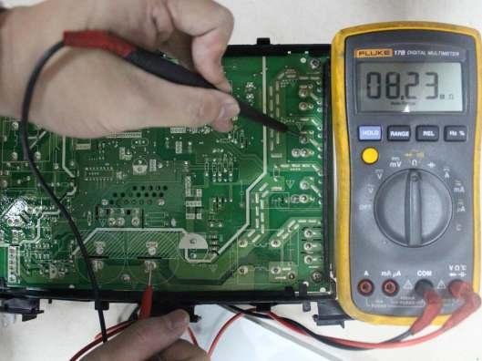
9 9.3.2 Indoor / outdoor unit s communication diagnosis and solution (E1) Error Code E1 Malfunction decision conditions Supposed causes Wiring mistake Trouble shooting: Indoor unit does not receive the feedback from outdoor unit during 110 seconds and this condition happens four times continuously. Indoor or outdoor PCB faulty Power off, then turn on the unit 5 seconds later(reconnect the power wire ).Is the error still displaying after several minutes? Measure Vs, is it moving alternately with positive value? (Vs is the voltage between L2 and S of outdoor unit. Connect the red pin of multimeter with L2 port, black pin with S port) Check all the wiring with outdoor units. Is the wiring to the outdoor main PCB connect ed correctly? Is the reactor connected well? Measure the resistance of the reactor(the one without capacitor ). If it is zero,follow the below step. If not, replace a new reactor. Check all the wiring with indoor units. Is the wiring to the indoor main PCB connected correctly? Replace the outdoor main PCB. Replace the indoor main PCB. Power on. Is the error extinguished? Power on. Is the error extinguished? Replace the indoor main PCB. Replace the outdoor main PCB. 37


10 Remark: Use a multi-meter to test the DC voltage between L2 port and S port of outdoor unit. The red pin of multi-meter connects with L2 port while the black pin is for S port. When AC is normal running, the voltage will move alternately between -50V to 50V. If the outdoor unit has malfunction, the voltage will move alternately with positive value. While if the indoor unit has malfunction, the voltage will be a certain value. Remark: Use a multi-meter to test the resistance of the reactor which does not connect with capacitor. The normal value should be around zero ohm. Otherwise, the reactor must have malfunction and need to be replaced. 38
11 9.4.3 Zero crossing detection error diagnosis and solution (E2) Error Code E2 Malfunction decision conditions When PCB does not receive zero crossing signal feedback for 4 minutes or the zero crossing signal time interval is abnormal. Supposed causes Connection mistake Trouble shooting: PCB faulty Check if the connections and power supply is normal? Correct the connections. Turn on the unit when the power supply is good. Indoor main PCB is defective. Replace indoor main PCB. 39
12 9.4.4 Fan speed has been out of control diagnosis and solution (E3) Error Code E3 Malfunction decision When indoor fan speed keeps too low (300RPM) for certain time, conditions the unit will stop and the LED will display the failure. Supposed causes Wiring mistake Fan assembly faulty Fan motor faulty PCB faulty Trouble shooting: Shut off the power supply and turn it on 5 seconds later. Is it still displaying the error code? The unit operates normally. Shut off the power supply, rotate the fan by hand. Does it rotate properly? Find out the cause and have it solved. For example, check whether the fan is blocked or the bearing is broken? Check the wires of fan motor. Are all the connections good? Correct the connections. Check whether the fan motor is normal through index 1? Replace the fan motor If the malfunction is still existing, replace the main PCB Check whether the main PCB is normal through index 2? Replace the main PCB. The malfunction is solved? 40
13 Index 1: 1. Indoor AC fan motor Measure the resistance value of each winding by using the tester. For the definite value of the resistance, refer to page61 and page64. Index2: 1: Indoor AC fan motor Power on and set the unit running in fan mode at high fan speed. After running for 15 seconds, measure the voltage of pin1 and pin2. If the value of the voltage is less than 100V(208~240V power supply)or 50V(115V power supply), the PCB must have problems and need to be replaced. 41

14 9.4.5 Open circuit or short circuit of temperature sensor diagnosis and solution (E5) Error Code E5 Malfunction decision conditions If the sampling voltage is lower than 0.06V or higher than 4.94V, the LED will display the failure. Supposed causes Wiring mistake Sensor faulty PCB faulty Trouble shooting: Check the connections between temperature sensor and main PCB. Are the connections good? Correct the connections. Check the resistance value of the sensor via table1(p64)and table 2(p65), is it normal? Replace indoor or outdoor main PCB. Replace the sensor and check if the problem happen again? 42
15 9.4.6 Refrigerant Leakage Detection diagnosis and solution (EC) Error Code EC Malfunction decision conditions Define the evaporator coil temp.t2 of the compressor just starts running as Tcool. In the beginning 5 minutes after the compressor starts up, if T2 <Tcool-2 does not keep continuous 4 seconds and this situation happens 3 times, the display area will show EC and AC will turn off. Supposed causes T2 sensor faulty Indoor PCB faulty System problems, such as leakage or blocking. Trouble shooting: Shut off the power supply and turn it on 5 seconds later. Is it still displaying the error code? Is there cool air blowing out from indoor air outlet? Check if T2 sensor is well fixed. Correct the installation or replace T2 sensor. Does the problem remain again? Is there any leakage? Especially the connection parts, such as the gas valve and the liquid valve. Replace indoor PCB. Repair the leakage and recharge the refrigerant. Is there any block ing? (Such as the capillary or the welded points of the pipes.) Clear the blocking. 43
16 9.4.7 IPM malfunction or IGBT over-strong current protection diagnosis and solution (P0) Error Code P0 Malfunction decision conditions When the voltage signal that IPM send to compressor drive chip is abnormal, the display LED will show P0 and AC will turn off. Supposed causes Wiring mistake IPM malfunction Outdoor fan assembly faulty Compressor malfunction Outdoor PCB faulty Trouble shooting: Check if the wiring between main PCB and compressor connected by error and if the wires and connectors are broken? Correct the connection or replace the wires and connectors. IPM continuity check. Check if the IPM terminal resistance values are uniform. Refer to page 64. Replace the IPM board or replace the main PCB if the IPM board and main PCB are integrated together. Check if the outdoor fan runs properly or the outdoor unit ventilation is good. please refer to the below remark, check whether the resistance of the fan motor is normal. If not, replace the fan motor. Check if the compressor resistance values are uniform.refer to page 63. Replace the compressor. Replace the outdoor main PCB if the main PCB and IPM are separate. Remark: 1) KSID012-H115Q-I model: Measure the black pin and red pin of the motor connector, the resistance should be around 50Ω at 20 (68 ) 2) KSID016-H215Q-I model: Measure the black pin and red pin of the motor connector, the resistance should be around 84.5Ω at 20 (68 ) 3) KSID022-H215Q-I model: Measure the black pin and red pin of the motor connector, the resistance should be around 88.5Ω at 20 (68 ) 4) 44

17 P-U P-V 45


18 P-W P-N 46
19 9.4.8 High temperature protection of compressor top diagnosis and solution (P2) Error Code P2 Malfunction decision If the sampling voltage is not 5V, the LED will display the failure. conditions Supposed causes Power supply problems. System leakage or block PCB faulty Trouble shooting: Check if the air flow system of indoor and outdoor units are obstructed? Clear up the air inlet and outlet or the heat exchanger of indoor and outdoor units. Turn off the power supply and turn it on 10 minutes later. Check if the unit can start normally. Check if all the connection, especially the connection of OLP (Over Load Protector) sensor is good. Correct the connection. Check if the refrigerant charge volume is normal? Measure the resistance between the two ports of the OLP. Is it zero? Replace the OLP. Replace the outdoor control PCB. Refrigerant system is blocked, such as capillary or welded point of pipes. Recharge the correct refrigerant volume. 47
20 9.4.9 Inverter compressor drive error diagnosis and solution (P4) Error Code P4 Malfunction decision An abnormal inverter compressor drive is detected by a special conditions detection circuit, including communication signal detection, voltage detection, compressor rotation speed signal detection and so on. Supposed causes Wiring mistake IPM malfunction Outdoor fan ass y faulty Compressor malfunction Outdoor PCB faulty Trouble shooting: Check if the wiring between main PCB and compressor connected by error and if the wires and connectors are broken? Correct the connection or replace the wires and connectors. IPM continuity check. Check if the IPM terminal resistance values are uniform. Refer to page 64. Replace the IPM board or replace the main PCB if the IPM board and main PCB are integrated together. Check if the outdoor fan runs properly or the outdoor unit ventilation is good. For KSID012-H115Q-I models, refer to the solution of fan speed has been out of control malfunction. Find out the cause and have it solved. For other models, please refer to the below remark, check whether the resistance of the fan motor is normal. If not, replace the fan motor. Check if the compressor resistance values are uniform.refer to page 63. Replace the outdoor main PCB if the main PCB and IPM are separate. Replace the compressor. Remark: 1) KSID012-H115Q-I model: Measure the black pin and red pin of the motor connector, the resistance should be around 50Ω at 20 (68 ) 2) KSID016-H215Q-I model: Measure the black pin and red pin of the motor connector, the resistance should be around 84.5Ω at 20 (68 ) 3) KSID022-H215Q-I model: Measure the black pin and red pin of the motor connector, the resistance should be around 88.5Ω at 20 (68 ) 48
21 Main parts check 2. Temperature sensor checking Disconnect the temperature sensor from PCB, measure the resistance value with a tester. Temperature Sensors. Room temp.(t1) sensor, Indoor coil temp.(t2) sensor, Outdoor coil temp.(t3) sensor, Outdoor ambient temp.(t4) sensor, Compressor discharge temp (T5) sensor. Measure the resistance value of each winding by using the multi-meter. 49
22 Appendix 1 Temperature Sensor Resistance Value Table for T1,T2,T3,T4 ( --K) K Ohm K Ohm K Ohm K Ohm
23 Appendix 2 Temperature Sensor Resistance Value Table for T5 ( --K) K Ohm K Ohm K Ohm K Ohm
24 Appendix 3:

25 3. Compressor checking Measure the resistance value of each winding by using the tester. Position Resistance Value DA108X1C-23EZ DA130M1C-31FZ DA150S1C-20FZ Blue - Red 1.1Ω 1.77Ω 0.95Ω Blue - Black Red - Blue (20 /68 ) (20 /68 ) (20 /68 ) 53
26 3. IPM continuity check Turn off the power, let the large capacity electrolytic capacitors discharge completely, and dismount the IPM. Use a digital tester to measure the resistance between P and UVWN; UVW and N. Digital tester rmal resistance value Digital tester rmal resistance value (+)Red (-)Black (+)Red (-)Black P N U U V V (Several MΩ) W W (+)Red N (Several MΩ) 4: Indoor AC Fan Motor Measure the resistance value of each winding by using the tester. Position Black - Red White - Black Resistance Value RPG15A RPG28H RPG45B 75Ω±8% 183.6Ω±8% 112Ω±8% 118.5Ω±8% (20 /68 ) (20 /68 ) (20 /68 ) (20 /68 ) (Brand: Weiling) (Brand: Weiling) (Brand: Weiling) (Brand: Dayang) 150Ω±8% 206Ω±8% 82Ω±8% 78.5Ω±8% (20 /68 ) (20 /68 ) (20 /68 ) (20 /68 ) (Brand: Weiling) (Brand: Weiling) (Brand: Weiling) (Brand: Dayang) 54
27 5: Pressure On Service Port Cooling chart: ( ) ODT IDT (23.89) (29.44) (35) (40.56) (46.11) BAR 70/ BAR 75/ BAR 80/ ( ) ODT (23.89) 85 (29.44) IDT (35) 105 (40.56) 115 (46.11) PSI 70/ PSI 75/ PSI 80/ ( ) ODT (23.89) 85 (29.44) IDT (35) 105 (40.56) 115 (46.11) MPA 70/ MPA 75/ MPA 80/
28 Heating Chart: ODT 57/53 47/43 37/33 27/23 17/13 ( ) IDT (13.89/11.67) (8.33/6.11) (2.78/0.56) (-2.78/-5) (-8.33/-10.56) BAR BAR BAR ODT 57/53 47/43 37/33 27/23 17/13 ( ) IDT (13.89/11.67) (8.33/6.11) (2.78/0.56) (-2.78/-5) (-8.33/-10.56) PSI PSI PSI ODT 57/53 47/43 37/33 27/23 17/13 ( ) IDT (13.89/11.67) (8.33/6.11) (2.78/0.56) (-2.78/-5) (-8.33/-10.56) MPA MPA MPA
29 The Klimaire logo is a registered Trademark of Klimaire Products Inc. Copyright 2016 Klimaire Products Inc NW 89 Place, Doral, FL USA Tel: (305) Fax: (305) sales@klimaire.co The design and specifications are subject to change without prior notice for product improvement. Consult with the sales agency or manufacturer for details.
QUARTZ INVERTER TROUBLESHOOTING GUIDE
 QUARTZ INVERTER TROUBLESHOOTING GUIDE QIN415H2V31 QIN618H2V31 QIN721H2V31 QIN1129H2V31 INVERTER MINI SPLIT SYSTEM WARNING The information contained in the manual is intended for use by a qualified service
troubleshooting Outdoor Unit: KSIE009-H221-O, KSIE012-H220-O, KSIE018-H220-O KSIE024-H220-O, KSIR036-H218, KSIR048-H218
 troubleshooting Table of Contents 1. Troubleshooting Model Numbers: Indoor Unit: KDIR09-H2, KTIR09-H2, KUIR09-H2 KDIR12-H2; KTIR12-H2, KUIR12-H2 KDIR18-H2, KTIR18-H2, KUIR18-H2 KDIR24-H2, KTIR24-H2, KUIR24-H2
LUV INVERTER SERIES. Self-diagnostics and Trouble-shooting. Part 2 of 2 42/38LUV028H 42/38LUV035H 42/38LUV052H 42/38LUV065H 42/38LUV070H 42/38LUV080H
 LUV INVERTER SERIES Part 2 of 2 Self-diagnostics and Trouble-shooting 42/38LUV028H 42/38LUV035H 42/38LUV052H 42/38LUV065H 42/38LUV070H 42/38LUV080H MAJOR COMPONENT CHECKING COMPRESSOR Use a multi-meter
KMIR. Multi outdoor units. troubleshooting Multi zone CONDENSING UNITS MKMIR218-H221, KMIR327-H217, KMIR436-H217, KMIR545-H219.
 Multi outdoor units KMIR troubleshooting Multi zone CONDENSING UNITS Model Numbers: MKMIR218-H221, KMIR327-H217, KMIR436-H217, KMIR545-H219 Table of Contents 1. Trouble Shooting WARNING Installation MUST
LIGHT COMMERCIAL. Troublesooting
 LIGHT COMMERCIAL Troublesooting 2. 2.1 Display board 2.1.1 Icon explanation on indoor display board (Super slim cassette 24K). 2.1.2 Icon explanation on indoor display board (Compact cassette 12K, 18K).
PART7. Trouble Shooting
 PART7. Trouble Shooting 1. Indoor Unit Error Display Display E0 E1 E2 E3 E5 LED STATUS EEPROM parameter error Indoor unit and outdoor unit communication protection Zero-crossing signal error Indoor fan
SERVICE MANUAL Room Air Conditioner DC Inverter Multi Split Outdoor units
 SERVICE MANUAL Room Air Conditioner DC Inverter Multi Split Outdoor units FS2MIF-141AE2 FS2MIF-181AE2 FS3MIF-211AE2 FS3MIF-271AE2 FS4MIF-281AE2 FS4MIF-361AE2 FS5MIF-421AE0 NOTE: Before servicing the unit,
SERVICE MANUAL MIDEA AIRCONDITIONER EUROPE MARKET SUPER DC INVERTER MULTI TYPE
 SERVICE MANUAL MIDEA AIRCONDITIONER EUROPE MARKET SUPER DC INVERTER MULTI TYPE M2OE-14HFN1-Q M2OF-18HFN1-Q M3OE-21HFN1-Q M3OE-27HFN1-Q M4OE-28HFN1-Q M4OB-36HFN1-Q M5OE-42HFN1-Q DC MULTI OUTDOOR UNITS CONTENTS
BRIVIS DUCTED INVERTER SERVICE MANUAL DRCi
 BRIVIS DUCTED INVERTER SERVICE MANUAL DRCi 1 TABLE OF CONTENTS TABLE OF CONTENTS... 2 IMPORTANT NOTE... 3 FAULT FINDING AND DIAGNOSTICS... 3 ABBREVIATIONS... 3 PCB S... 4 OUTDOOR MAIN PCB... 4 INDOOR PCB...
GAMA DOMÉSTICA MULTISPLIT Manual de Servicio
 GAMA DOMÉSTICA MULTISPLIT Manual de Servicio CONTENTS 1. General information of Outdoor Units... 2 2. Features... 3 3. Dimensions... 4 4. Refrigeration Cycle Diagram... 5 5. Wiring diagram... 7 6. Indoor
SERVICE MANUAL MIDEA AIRCONDITIONER SUPER DC INVERTER MULTI TYPE OUTDOOR UNITS
 SERVICE MANUAL MIDEA AIRCONDITIONER SUPER DC INVERTER MULTI TYPE OUTDOOR UNITS M2OE-14HFN1-Q M2OF-18HFN1-Q M3OE-21HFN1-Q M3OE-27HFN1-Q M4OE-28HFN1-Q M4OB-36HFN1-Q M5OE-42HFN1-Q Service manual CONTENTS
Service Manual. 9. Maintenance. 9.1 Precautions before Maintenance. discharge resistance or plug of soldering iron. Installation and Maintenance
 9. Maintenance 9.1 Precautions before Maintenance Service Manual pacitor after power off. - discharge resistance or plug of soldering iron A B A B - nance safely. 40 9.2 Error Code List O. 1 2 3 4 5 6
SERVICE MANUAL MIDEA SUPER DC INVERTER MULTI TYPE DC MULTI OUTDOOR UNITS
 SERVICE MANUAL MIDEA SUPER DC INVERTER MULTI TYPE DC MULTI OUTDOOR UNITS M2OD-16HFN1-Q M2OD-18HFN1-Q M3OD-21HFN1-Q M3OD-26HFN1-Q M4OD-28HFN1-Q M4OA-36HFN1-Q M5OC-36HFN1-Q M5OD-42HFN1-Q CONTENTS 1. GENERAL
6. Troubleshooting. 6-1 Basic items for trouble shooting. Samsung Electronics 17
 6. Troubleshooting Since the inverter air conditioner is equipped with Electrical control circuits at both Indoor & outdoor unit, the trouble shooting shall be performed according to the error mode. Inside
Fault Codes. J control
 J control Timer Temp Fault Codes 12 11 10 9 8 7 6 5 4 3 2 1 30 29 28 27 26 25 24 23 22 21 20 Enter unit inspection mode by pushing the UP and DOWN buttons simultaneously for two seconds. Ensure that the
No Operation of air conditioner Explanation
 12. Troubleshooting 12-1 Items to be checked first 1. The input voltage should be rating voltage ±10% range. The air conditioner may not operate properly if the voltage is out of this range. 2. Is the
LG Air Conditioning Universal & Multi Split Fault Codes Sheet. Universal and Multi Split Units
 Universal and Multi Split Units If there is a fault on any LG Universal or Multi unit, a two digit number will appear on the remote controllers led display. If the unit does not have a remote controller
12. Troubleshooting Items to be checked first. Samsung Electronics
 12. Troubleshooting 12-1 Items to be checked first 1. The input voltage should be rating voltage ±10% range. The air conditioner may not operate properly if the voltage is out of this range. 2. Is the
SPLIT TYPE ROOM AIR CONDITIONER WALL MOUNTED TYPE
 SPLIT TYPE ROOM AIR CONDITIONER WALL MOUNTED TYPE Indoor unit ASYA24LCC ASYA24LCC ASYA24LCC Outdoor unit AOYR24LCC AOYR24LCD AOYR24LCL CONTENTS SPECIFICATIONS..................1 DIMENSIONS.....................
9. Maintenance. 9.1 Precautions before Maintenance. Service Manual. electrolytic capacitor after power off. maintenance safely.
 9. Maintenance 9.1 Precautions before Maintenance electrolytic capacitor after power off. A B A B maintenance safely. 50 9.2 Error Code List Unit o. ame Display 8 nixie 0.5s) Operation Indicator Cool Indicator
Driftsinstruks. Utopia kontroller feilkoder PCP-2HTE og PC-ART. Vi håper de får stor glede av et Novema kulde produkt!
 Driftsinstruks Utopia kontroller feilkoder PCP-2HTE og PC-ART Vi håper de får stor glede av et vema kulde produkt! www.novemakulde.no 8/14 TROUBLESHOOTING 8.2. TROUBLESHOOTING PROCEDURE 8.2.1. ALARM CODE
WALL MOUNTED type SPLIT TYPE ROOM AIR CONDITIONER. Models
 SPLIT TYPE ROOM AIR CONDITIONER WALL MOUNTED type Models Indoor unit ASH9LSACW ASH12LSACW Outdoor unit AOH9LSAC AOH12LSAC CONTENTS SPECIFICATIONS...................... 1 DIMENSIONS..........................
LG Air conditioning CAC and Multi Split unit Fault code sheet Universal and Multi Split Units
 Universal and Multi Split Units If there is fault on any LG universal or multi unit a two digit number will appear on the remote controllers led display. If the unit does not have a remote controller the
3. SERVICE TOOLS Inverter checker RSUK09-17 CLIMATE COMFORT. All Seasons. Heating. Air Conditioning. Applied Systems.
 All Seasons CLIMATE COMFORT Heating 3. SERVICE TOOLS 3.2. Inverter checker RSUK09-17 Air Conditioning Applied Systems Refrigeration 3.2. Inverter checker RSUK09-17: index 1. Outlook 2. How to connect?
SPLIT TYPE ROOM AIR CONDITIONER FLOOR TYPE
 SPLIT TYPE ROOM AIR CONDITIONER FLOOR TYPE Indoor unit AGYF09LAC AGYFLAC AGYFLAC AGYFLAC Outdoor unit AOYV09LAC AOYVLAC AOYVLAC AOYVLAL CONTENTS SPECIFICATIONS..................... DIMENSIONS.........................
SPLIT TYPE ROOM AIR CONDITIONER. WALL MOUNTEDtype INVERTER. Models Indoor unit Outdoor unit AOU18RLXFW AOU24RLXFW ASU18RLF ASU24RLF R410A
 SERVICE INSTRUCTION SPLIT TYPE ROOM AIR CONDITIONER WALL MOUNTEDtype INVERTER Models Indoor unit Outdoor unit ASU18RLF ASU24RLF AOU18RLXFW AOU24RLXFW R410A CONTENTS 1. DESCRIPTION OF EACH CONTROL OPERATION
9. Maintenance. 9.1 Error Code List. Service Manual. Installation and Maintenance
 9. Maintenance 9.1 Error Code List o. ame Display Method of Outdoor Display Method of Indoor Unit Unit Indicator has 3 kinds of Indicator Display (during display status during Dual-8 ing, O 0.5s OFF ing,
HP21 SERVICE SUPPLEMENT UNIT INFORMATION. TSC6 Two-Speed Control
 SERVICE UNIT INFORMATION SUPPLEMENT HP21 Corp. 9426 L10 Litho U.S.A. All HP21-4 and -5 units (single and three phase) are equipped with a TSC6 two-speed control. The TSC6 (A14) two-speed control contains
4.Failure phenomenon. Mirage comes out from indoor. When the cold air from AC cools the indoor air. unit
 4.Failure phenomenon Phenomenon Mirage comes out from indoor unit Noise Sometimes, the room is smelly when heating, there is no wind at the beginning of starting unit Causing explanation When the cold
Subject Underhood G System Error Codes and Symptoms System or Parts affected
 System or Parts affected Index Underhood70G (V90Gxxx) System or Parts affected... 1 Overview... 1 Identifying your System... 1 Retrieving Logged Error Messages... 1 Error Messages... 3 Error Message Table...
MODEL UC 14YFA. Hitachi. Power Tools TECHNICAL DATA AND SERVICE MANUAL CHARGER UC 14YFA SPECIFICATIONS AND PARTS ARE SUBJECT TO CHANGE FOR IMPROVEMENT
 MODEL UC 14YFA Hitachi Power Tools CHARGER UC 14YFA TECHNICAL DATA AND SERVICE MANUAL U LIST No. F888 Aug. 2003 SPECIFICATIONS AND PARTS ARE SUBJECT TO CHANGE FOR IMPROVEMENT CONTENTS Page 1. PRODUCT NAME...1
Parts Lists. Forward Series. Rev. Feb. 2017
 s HSU09VHJ(DB)-G / HSU09VHJ(DB)-W HSU12VHJ(DB)-G / HSU12VHJ(DB)-W HSU18VHJ(DB)-G / HSU18VHJ(DB)-W HSU24VHJ(DB)-G / HSU24VHJ(DB)-W 1800 Valley Road Wayne, NJ 07470 Tel +973.617.1800 www.haier.com - Edition
INSTALLATION MANUAL. Free Joint Multi & Multi-Split Type Room Air Conditioner (Cooling and Heating)
") INSTALLATION MANUAL Free Joint MH040FXEA2A MH052FXEA2A Fixed MH18VV1X MH19VV1X ENGLISH Free Joint Multi & Multi-Split Type Room Air Conditioner (Cooling and Heating) EΛΛHNIKA PORTUGUÊS ITALIANO ESPAÑOL
INSTALLATION MANUAL Free Joint MH040FXEA2A MH052FXEA2A Fixed MH18VV1X MH19VV1X ENGLISH Free Joint Multi & Multi-Split Type Room Air Conditioner (Cooling and Heating) EΛΛHNIKA PORTUGUÊS ITALIANO ESPAÑOL
ELECTRIC FENCE ENERGIZER SERVICE MANUAL MODEL 950 SERVICE MANUAL FOR OLLI 950 FENCE ENERGIZERS
 ELECTRIC FENCE ENERGIZER MODEL 950 SERVICE MANUAL Service Manual for OLLI 950 Page 1/16 Date 20.10.2014 Table of Contents...1 1. IMPORTANT SAFETY INSTRUCTIONS...2 2. SPECIFICATIONS...3 3. CONSTRUCTION...4
SERVICE MANUAL FREE COMBI SERIES FC-E24AI, FC-E28AI
 SERVICE MANUAL FREE COMBI SERIES FC-E24AI, FC-E28AI 1.Technical specifications Model Compressor Manufacturer/trademark Compressor Model Compressor Type L.R.A. (A) Compressor RLA(A) Compressor Power Input(W)
ACCESSORY KIT INSTALLATION INSTRUCTIONS
 ACCESSORY KIT INSTALLATION INSTRUCTIONS Low Ambient Accessory For Air Cooled Split-System Air Conditioners YD360/480/600, YJ-30/-40/-50 and J30/40/50 YD Models 642546-UAI-A-080 GENERAL Standard operation
MODEL : 55A240IUBEM ROTARY COMPRESSOR SPECIFICATION SHEET 1. APPLICATION 2. COMPRESSOR DATA 3. MOTOR DATA 4. ELECTRICAL COMPONENTS
 SPECIFICATION SHEET 1. APPLICATION H/P & Cooling Type Air conditioner Rated & Frequency... 208~230V 1Φ 60Hz Refrigerant.. R-22 2. COMPRESSOR DATA Pump Type Rolling Piston Type Displacement. 33.43cc/rev
POWER REGULATOR LD -40PSU
 JZ99D4121A AMPIFIRE AMPIFIRE TYPE D-4PSU ZJ-46A ISTRUCTI MAUA Manual number JZ99D4121 Sub number A Date of preparation ov. 2 Thoroughly read this instruction manual, and then use the unit correctly. Especially,
Parts Lists. Novel Series. Rev. Feb. 2017
 s HSU09VHG(DB)-G / HSU09VHG(DB)-W HSU12VHG(DB)-G / HSU12VHG(DB)-W HSU18VHG(DB)-G / HSU18VHG(DB)-W HSU24VHG(DB)-G / HSU24VHG(DB)-W 1800 Valley Road Wayne, NJ 07470 Tel +973.617.1800 www.haier.com - Edition
13A-1 FUEL CONTENTS MULTIPOINT FUEL INJECTION (MPI) FUEL SUPPLY... 13B
 FUEL SUPPLY... 13B") 13A-1 FUEL CONTENTS MULTIPOINT FUEL INJECTION (MPI)... 13A FUEL SUPPLY... 13B 13A-2 MULTIPOINT FUEL INJECTION (MPI) CONTENTS GENERAL INFORMATION... 3 SERVICE SPECIFICATIONS... 6 SEALANT... 6 SPECIAL TOOLS...
13A-1 FUEL CONTENTS MULTIPOINT FUEL INJECTION (MPI)... 13A FUEL SUPPLY... 13B 13A-2 MULTIPOINT FUEL INJECTION (MPI) CONTENTS GENERAL INFORMATION... 3 SERVICE SPECIFICATIONS... 6 SEALANT... 6 SPECIAL TOOLS...
5. TROUBLE DIAGNOSIS
 . TROBLE DIAGNOSIS -1. Contents of Remote Controller Switch Alarm Display... -2-2. Outdoor nit Control anel LED Display... -4-3. AC System Alarm Codes... - -4. Inspection of arts (Outdoor nit)... -68 -.
Phoenix Inverter
 Manual EN Handleiding NL Manuel FR Anleitung DE Manual ES Appendix Phoenix Inverter 12 250 12 375 12 500 12 800 24 250 24 375 24 500 24 800 48 250 48 375 48 500 48 800 1. Safety instructions WARNING: ELECTRIC
OPEN/CLOSE SERVICE ELECTRIC ACTUATORS OPERATION AND MAINTENANCE MANUAL COMMERCIAL AND INDUSTRIAL VALVES AND AUTOMATION
 SERIES 1000-X OPEN/CLOSE SERVICE ELECTRIC ACTUATORS OPERATION AND MAINTENANCE MANUAL COMMERCIAL AND INDUSTRIAL VALVES AND AUTOMATION Publication S1000X-110 VER0215-1 For information on this product and
TOWA SEIDEN INDUSTRIAL CO., LTD.
 INSTRUCTION MANUAL SOUNDING LEVEL METER MODEL: TLX-120AP/200AP Meanings of indications for safety used in this Instruction Manual are as follows. WARNING: Indicates that improper handling assumes the risk
MPPT Solar Integrated Inverters (500VA~2500VA) User Manual THE SOLAR TECH CO.,LTD. Solar Integrated Inverter Series 500VA~2500VA 13.
 User Manual THE SOLAR TECH CO.,LTD. Solar Integrated Inverter Series 500VA~2500VA 13.") MPPT Solar Integrated Inverters (500VA~2500VA) User Manual THE SOLAR TECH CO.,LTD. - 1 - Table of Contents 1. SALIENT FEATURES...3 2.. PRODUCT INSTALLATION & PRECAUTIONS...3 2.1. PRODUCT INSTALLATION &
MPPT Solar Integrated Inverters (500VA~2500VA) User Manual THE SOLAR TECH CO.,LTD. - 1 - Table of Contents 1. SALIENT FEATURES...3 2.. PRODUCT INSTALLATION & PRECAUTIONS...3 2.1. PRODUCT INSTALLATION &
Application Engineering Europe
 Date of last update: Feb-12 Ref: D7.8.4/0112-0212/E Application Engineering Europe CORESENSE DIAGNOSTICS FOR STREAM REFRIGERATION COMPRESSORS 1/17 1 Introduction CoreSense is an ingredient brand name for
SBC / 2140 / Stage Battery Charger User Manual
 SBC - 2130 / 2140 / 2150 3 Stage Battery Charger User Manual Keep this manual in a safe place for quick reference at all times. This manual contains important safety and operation instructions for correct
SERVICE MANUAL USA. Hot Island 48-2 level
 SERVICE MANUAL Hot Island 48-2 level - NOTICE - This manual is prepared for the use of trained Service Technicians and should not be used by those not properly qualified. If you have attended a training
PRE CHECK DI 456. w/ Tachometer. w/o Tachometer. Hand held Tester AUTOMATIC TRANSMISSION (A340E, A340F) 2003 TOYOTA TACOMA (RM1002U) D10837 D00729
 2003 TOYOTA TACOMA (RM1002U) D10837 D00729") DI456 w/ Tachometer w/o Tachometer D10837 PRECHECK DI8Z403 1. DIAGNOSIS SYSTEM (a) Description When troubleshooting OBD II vehicles, the only difference from the usual troubleshooting procedure is that
DI456 w/ Tachometer w/o Tachometer D10837 PRECHECK DI8Z403 1. DIAGNOSIS SYSTEM (a) Description When troubleshooting OBD II vehicles, the only difference from the usual troubleshooting procedure is that
Heat Recovery Ventilation
 .book Page i Thursday, March 30, 2000 3:31 PM Heat Recovery Ventilation VAM 500EJ VAM 800EJ VAM1000EJ VAM2000EJ VAM500~1000EJ VAM2000EJ Table of Contents i .book Page ii Thursday, March 30, 2000 3:31 PM
SERVICE MANUAL OUTDOOR UNIT. No. OB387
 SPLIT-TYPE, HEAT PUMP AIR CONDITIONERS Revision C: MUH-A25VB - E has been added. Please void OB87 REVISED EDITION-B. OUTDOOR UNIT SERVICE MANUAL HFC utilized R40A. OB87 REVISED EDITION-C Wireless type
PANcharge1k Battery Charger User's Manual
 PANcharge1k Battery Charger User's Manual Ver.1.00E Table of Contents 1. Important Safety Instructions... 3 1-1 General Safety Precautions... 3 1-2 Battery Precautions... 3 1-3 Electromagnetic Disturbance...
RAC Product Trouble Shooting Guide
 1 RAC Product Trouble Shooting Guide Model : Wall Mount Inverter Type CAUTION Make sure to fully read and understand the safety precautions described in the SVC manual before SVC. Only authorized personnel
SECOND GENERATION Use this guide with unit serial number prefix beginning with BWF using Terra Power separator.
 Technical Information and Diagnostic Guide for SECOND GENERATION Use this guide with unit serial number prefix beginning with BWF using Terra Power separator. This guide will assist you in becoming more
DC power supply connect to VF-AS1/PS1 Optional initial charger MCR-2550 Instruction manual
 DC power supply connect to VF-AS1/PS1 Optional initial charger Instruction manual NOTE 1. Make sure that this instruction manual is delivered to the end user of the optional initial charger. 2. Read this
YN018GMFI16M2D-V V~ 60Hz 1Phase Serials: PRE
 Sale model: ProdCode: YN018GMFI16M2D-V1 220057000460 208-230V~ 60Hz 1Phase PRE 50130047 No. Part Name Quantity BOM code Bin Code Remark 1 Rear net 1 2011481G0001 8 2 Ambient temperature sensor assembly
 Pagina 1 di 1 INSPECTION In-car air sensor is located at crash pad. It is installed with humidity sensor. It will detect interior, which will be used for discharge control, sensor failsafe, door control,
 Page 1 of 50 Section 412-00: Climate Control System General Information DIAGSIS AND TESTING 1997 Mark VIII Workshop Manual Climate Control System Special Service Tool(s) 73 Digital Multimeter 105-R0051
Duplex Booster System Instruction Manual
 Duplex Booster System Instruction Manual ISO 9001 Certified Walrus America Inc Congratulations on your purchase of Walrus IC Series Inverter Control System. Please read all instructions carefully before
1. Inspection and Maintenance
 1. and Maintenance Mandatory Be sure to inspect the inverter regularly and periodically to prevent it from breaking down because of the environment of use, such as temperature, humidity, dust and vibration,
Northwest RV Supply Manual Compliments of Printed From TROUBLESHOOTING
 TROUBLESHOOTING for the 5 BUTTON 3109228.001 COMFORT CONTROL CENTER SYSTEM INTRODUCTION The Comfort Control Center control system can be used to operate the following Duo-Therm Units: Roof Top Air Conditioners
Owner s Information Manual
 50ES---A and 50VL---C Comfort 13SEERThreePhase2½---5NominalTons (Sizes 30---60) Comfort 14 SEER Single and Three Phase 2---5 Nominal Tons (Sizes 24---60) Single Packaged Air Conditioner System With Puronr
Ultra Sine Inverter (US) Generation 4 (G4) User Guide
 Generation 4 (G4) User Guide") IBS Intelligent Battery System GmbH Seestrasse 24, CH-3600 Thun, Schweiz Tel: +41 33 221 06 16 Fax: +41 33 221 06 17 E-Mail: info@ibs-tech.ch Ultra Sine Inverter (US) Generation 4 (G4) User Guide IBS-USG4_en_v2.0.3.doc
IBS Intelligent Battery System GmbH Seestrasse 24, CH-3600 Thun, Schweiz Tel: +41 33 221 06 16 Fax: +41 33 221 06 17 E-Mail: info@ibs-tech.ch Ultra Sine Inverter (US) Generation 4 (G4) User Guide IBS-USG4_en_v2.0.3.doc
SERVICE MANUAL MU-A09YV - E1 MU-A09YV - MU-A12YV - E1 HFC. Wireless type Models SPLIT-TYPE, AIR CONDITIONERS. No. OB330 R410A CONTENTS.
 SPLIT-TYPE, AIR CONDITIONERS Revision A: MU-A2YV - E can be connected to MCF-A2WV - E. Please void OB330. SERVICE MANUAL Wireless type Models E MU-A07YV - E MU-A09YV - MU-A2YV - E HFC utilized R40A No.
Wall Mounted Mini Split Air Conditioner
 Wall Mounted Mini Split Air Conditioner OWNER S MANUAL Model: KFH-18/KFH-18-1 Please read this owner s Manual carefully before operating the unit. TABLE OF CONTENTS OPERATION AND MAINTENANCE....1-13 The
INSTALLATION AND MAINTENANCE
 ISTALLATIO AD MAITEACE TROUBLESHOOTIG Content: 1. Precautions before Performing Inspection or Repair 2. Confirmation 3. Flashing LED of Indoor/Outdoor Unit and Primary Judgement 4. How to Check Simply
ASU18RLB ASU24RLB AOU18RLB AOU24RLB SPLIT TYPE ROOM AIR CONDITIONER WALL MOUNTED TYPE CONTENTS
 SPLIT TYPE ROOM AIR CONDITIONER WALL MOUNTED TYPE Indoor unit ASU8RL ASURL Outdoor unit AOU8RL AOURL CONTENTS SPECIFICATIONS................... DIMENSIONS...................... REFRIGERANT SYSTEM DIAGRAM....
SERVICE MANUAL OUTDOOR UNIT. No. OB386
 SPLIT-TYPE AIR CONDITIONERS Revision D: MU-A20VB- E and MU-A5VB- E have been added. Please void OB86 REVISED EDITION-C. OUTDOOR UNIT SERVICE MANUAL HFC utilized R40A No. OB86 REVISED EDITION-D Models MU-A20VB-
A/C-HEATER SYSTEM - AUTOMATIC
 A/C-HEATER SYSTEM - AUTOMATIC 1988 Toyota Celica 1988 Automatic A/C-Heater Systems Celica * PLEASE READ THIS FIRST * CAUTION: When discharging air conditioning system, use only approved refrigerant recovery/recycling
Installation Diagram of Indoor Unit and Outdoor Unit /12K 18K 24K
 /12K 18K 24K Installation Diagram of Indoor Unit and Outdoor Unit 1-1 1-1 1-1 1-1 1-2 1-2 2-1 2-1 2-2 2-3 Accessory and Option Specifications... 2-3-1 3-1 Checking before use... 3-1 3-2 Display Error and
EcoNet and Flash Codes
 The error codes below will be displayed at the EcoNet Control Center under Service window / Current Faults or in the Fault History and will be time & date stamped. VSODC (Variable Speed Outdoor Unit Control
Users Manual. Defender 1 8.0KW to 14.0KW Online Emergency Lighting Inverter. Technical Manual # Revision B
 Users Manual Defender 1 8.0KW to 14.0KW Online Lighting Inverter Technical Manual #018-0102-01 Revision B Phone: 1.877.DSPM.POWER 1.877.377.6769 Fax: 909.930.3335 Website: www.dspmanufacturing.com E-Mail:
SERVICE INSTRUCTION R410A. SPLIT TYPE ROOM AIR CONDITIONER Compact Wall Mounted Wall Mounted / Floor Compact Cassette / Slim Duct INVERTER MULTI
 SPLIT TYPE ROOM AIR CONDITIONER Compact Wall Mounted Wall Mounted / Floor Compact Cassette / Slim Duct INVERTER MULTI SERVICE INSTRUCTION Models Indoor unit Outdoor unit ASU7RLF ASU9RLF ASU2RLF ASU8RLF
A L L Diagnostic Trouble Codes ( DTC ): P Code Charts P161B DTC P161B ECM/PCM INTERNAL ERROR - TORQUE CALCULATION
: P Code Charts P161B DTC P161B ECM/PCM INTERNAL ERROR - TORQUE CALCULATION") 2006 Kia Truck Sedona V6-3.8L Copyright 2013, ALLDATA 10.52 Page 1 A L L Diagnostic Trouble Codes ( DTC ): P Code Charts P161B DTC P161B ECM/PCM INTERNAL ERROR - TORQUE CALCULATION ENERAL DESCRIPTION Component
2006 Kia Truck Sedona V6-3.8L Copyright 2013, ALLDATA 10.52 Page 1 A L L Diagnostic Trouble Codes ( DTC ): P Code Charts P161B DTC P161B ECM/PCM INTERNAL ERROR - TORQUE CALCULATION ENERAL DESCRIPTION Component
RENEWABLE RESOURCES FOR RENEWABLE LIFE
 TM Trillion Customers, Maximum Services RENEWABLE RESOURCES FOR RENEWABLE LIFE Solar Refrigerator Solar AC www.teramaxindia.com HYBRID AC/DC SOLAR AIR CONDITIONER The system priority consume DC power from
SERVICE MANUAL MULTI DECK HOT MERCHANDISERS MD Versions. Solid back 3 and 5 level Pass through 3 and 5 level
 SERVICE MANUAL MULTI DECK HOT MERCHANDISERS MD 60-100 - 120 Versions Solid back 3 and 5 level Pass through 3 and 5 level MD 60-3 solid back MD 100-3 pass through - NOTICE - This manual is prepared for
TECHNICAL SUPPORT MANUAL Split System Air Conditioner H4A3, 3 Phase
 TECHNICAL SUPPORT MANUAL Split System Air Conditioner H4A3, 3 Phase DANGER, WARNING, CAUTION, and NOTE The signal words DANGER, WARNING, CAU- TION, and NOTE are used to identify levels of hazard seriousness.
Wiring diagrams on page 29 are for reference only. For detailed vehicle wiring refer to Navistar documents.
 1 10/2014 REV 7 !!Attention!! Before performing diagnostics: Wiring diagrams on page 29 are for reference only. For detailed vehicle wiring refer to Navistar documents. Check for Fault Codes using the
DI 244 DIAGNOSTICS AUTOMATIC TRANSMISSION DIB30 01 PRE CHECK
 DI244 DIAGNOSTICS PRECHECK DIB3001 1. DIAGNOSIS SYSTEM (a) Description When troubleshooting OBD II vehicles, the only difference from the usual troubleshooting procedure is that you connect to the vehicle
Technical Information and Diagnostic Guide
 Technical Information and Diagnostic Guide This guide will assist you in becoming more familiar with the working components of the NITE System and the proper steps and procedures to completely diagnose
C.E. Niehoff & Co. C840D Alternator Troubleshooting Guide CAUTION. Testing Guidelines. Hazard Definitions WARNING.
 C.E. Niehoff & Co. C840D Alternator Troubleshooting Guide WARNING Before troubleshooting any CEN products, the service technician should: read, understand, and agree to follow all information contained
PANASONIC FAULT CODE GUIDE. ECOi ECO-G - PACi
 PANASONIC FAULT CODE GUIDE ECOi ECO-G - PACi 1 Page INDEX P3 GHP ENGINE ISSUES P4 CENTRAL CONTROLLER ISSUES P5 ADDRESSING & COMMUNICATION PROBLEMS P6 SENSOR FAULTS P7 COMPRESSOR ISSUES P8 INCORRECT SETTINGS
VAL6 Infrared Heater KBE5S & KBE5L. (2-step) Maintenance Manual
 Maintenance Manual") VAL6 Infrared Heater KBE5S & KBE5L (2-step) Maintenance Manual Wiring Diagram of Burner Control KBE5S KBE5L 2-step Sequence Time Chart Operation Switch ON ignition OFF Fan Igniter Solenoid Pump 5 sec.
VAL6 Infrared Heater KBE5S & KBE5L (2-step) Maintenance Manual Wiring Diagram of Burner Control KBE5S KBE5L 2-step Sequence Time Chart Operation Switch ON ignition OFF Fan Igniter Solenoid Pump 5 sec.
Technical Information and Diagnostic Guide RestStar Use this guide with 5700XE RestStar Unit. Western Star 5700XE.
 Western Star 5700XE RestStar 4 10-2017 1 Technical Information and Diagnostic Guide RestStar Use this guide with 5700XE RestStar Unit 2390 Blackhawk Road P.O. Box 6007 Rockford, IL 61125 nitesystem.com
SERVICE Manual AIR CONDITIONER OUTDOOR UNIT UM27B1C3 INDOOR UNIT AM27B1C07 AM27B1C Installation. 2. Disassembly and Reassembly
 ROOM AIR CONDITIONER INDOOR UNIT AM27BC07 AM27BC3 OUTDOOR UNIT UM27BC3 SERVICE Manual AIR CONDITIONER. Installation CONTENTS 2. Disassembly and Reassembly 3. Troubleshooting 4. Exploded Views and Parts
Uninterruptible Power System
 USER'S MANUAL Emergency Backup Power Supply For Use With Computer Loads Only Power Surge/Noise Protection Intelligent Auto-Shutdown Software Internet Line Protection Cost Efficiency UPS 1 st Edition Uninterruptible
INSTRUCTION & INSTALLATION
 INSTRUCTION & INSTALLATION MANUAL MODELS: CCL-eHOME T1C16 CCL-eHOME T1C32 CCL-eHOME T2C16 CCL-eHOME T2C32 WALLBOX ehome SERIES WALLBOX ehome Instruction and Installation manual This document is copyrighted,
620 Magnolia Avenue Suite B Ontario, CA (909) Diagnostic and Troubleshooting. Golf Cart. Revision: A Date:
 Diagnostic and Troubleshooting. Golf Cart. Revision: A Date:") 620 Magnolia Avenue Suite B Ontario, CA 91762 (909) 923-1973 Diagnostic and Troubleshooting Golf Cart Revision: A Date: 9-25-13 Diagnostics Diagnostics information can be obtained by observing the fault
620 Magnolia Avenue Suite B Ontario, CA 91762 (909) 923-1973 Diagnostic and Troubleshooting Golf Cart Revision: A Date: 9-25-13 Diagnostics Diagnostics information can be obtained by observing the fault
37. FATC (FULL AUTO TEMP. CONTROL) CIRCUIT 6810
 CIRCUIT 6810") 5156 6810 37. FATC (FULL AUTO TEMP. CONTROL) CIRCUIT 6810 1) CONDENSOR FAN, AIR MIX MOTOR, SUN SENSOR, WATER TEMP SENSOR A. CONNECTOR INFORMATION 6810 5157 Connector Number (Pin Number, Color) Connecting
5156 6810 37. FATC (FULL AUTO TEMP. CONTROL) CIRCUIT 6810 1) CONDENSOR FAN, AIR MIX MOTOR, SUN SENSOR, WATER TEMP SENSOR A. CONNECTOR INFORMATION 6810 5157 Connector Number (Pin Number, Color) Connecting
TECHNICAL MANUAL 2013 CONSOLE MULTI DC INVERTER
 TECHNICAL MANUAL 2013 CONSOLE MULTI DC INVERTER MODELS Indoor units BCODM26A2 BCODM36A2 BCODM53A2 Outdoor units BD2M53A3 BD3M98A3 BD4M114A3 BD5M120A3 This manual has been created for informative purpose.
19,1 261,0 kw COOLING 23,7 333,0 kw HEATING
 199 RE ER RS SO AIR COOLED HEAT PUMP LIQUID CHILLERS 19,1 261,0 kw COOLING 23,7 333,0 kw HEATING R410A PLATE RCGROUP SpA 19632013 fiftycoolyears 200 VERSIONS: (R410A) Cooling capacity 19,2 261,0 kw Heating
Copeland Screw TM Compressors
 Copeland Screw TM Compressors Mechanical Guidelines for SHL & SHM Models using ESC-201 Control System Contents: Start-Up Procedure Operating Specifications Maintenance Trouble Shooting Guidelines Start-up
 TRACTION CONTROL SYSTEM 1996 Toyota Supra 1995-96 BRAKES Traction Control Supra DESCRIPTION Toyota Traction Control (TRAC) system controls engine torque and braking of the driving wheels. TRAC system is
NT-500 Technical Support Guide. For use by qualified company approved Technicians
 NT-500 Technical Support Guide For use by qualified company approved Technicians INTRODUCTION The NT-500 is designed to offer the full range of features required to perform radiofrequency denervation The
ZIP Economizer Fault Detection and Diagnostics (FDD) Table
 Table") Fault Detection and Diagnostics (FDD) Table Fault Detection Problem Diagnostic ction (in addition to alarm stored / transmitted) Potential Cause C Fault Code OT sensor predetermined range O damper returns
Fault Detection and Diagnostics (FDD) Table Fault Detection Problem Diagnostic ction (in addition to alarm stored / transmitted) Potential Cause C Fault Code OT sensor predetermined range O damper returns
MODEL UC 24YJ. Hitachi. Power Tools TECHNICAL DATA AND SERVICE MANUAL CHARGER UC 24YJ SPECIFICATIONS AND PARTS ARE SUBJECT TO CHANGE FOR IMPROVEMENT
 MODEL UC 24YJ Hitachi Power Tools CHARGER UC 24YJ TECHNICAL DATA AND SERVICE MANUAL U LIST No. F889 Oct. 2003 SPECIFICATIONS AND PARTS ARE SUBJECT TO CHANGE FOR IMPROVEMENT CONTENTS Page 1. PRODUCT NAME...
MODULATING SERVICE ELECTRIC ACTUATORS OPERATION AND MAINTENANCE MANUAL COMMERCIAL AND INDUSTRIAL VALVES AND AUTOMATION
 SERIES 000/S-X MODULATING SERVICE ELECTRIC ACTUATORS OPERATION AND MAINTENANCE MANUAL COMMERCIAL AND INDUSTRIAL VALVES AND AUTOMATION Publication S000X- VER045- For information on this product and other
SYSTEM AIR CONDITIONER
 SYSTEM AIR CONDITIONER INDOOR UNIT AC071MN4PKH AC090MN4PKH AC100MN4PKH AC120MN4PKH AC140MN4PKH CIRCULAR CASSETTE SERIES OUTDOOR UNIT AC090MXADKH AC100MXAD*H AC120MXAD*H AC140MXAD*H SYSTEM AIR CONDITIONER
AIR CONDITIONER SECTION AC CONTENTS AUTO
 AIR CONDITIONER SECTION AC CONTENTS AUTO PRECAUTIONS AND PREPARATION SRS Airbag Pretensioner Seatbelt... 4 A/C Refrigerant HFC134a Handling... 4 Compressor Oil... 4 Tube Connection... 4 O-Ring Part Number...
CEILING WALL type INVERTER
 SPLIT TYPE ROOM AIR CONDITIONER CEILING WALL type INVERTER Models Indoor unit AWY14LSAZ AWH14LSAZ AWY17LSAZ AWH17LSAZ Outdoor unit AOY14LSAWC AOH14LSAWC AOY17LSAWC AOH17LSAWC CONTENTS SPECIFICATIONS....................