HE Stewart Vacuum Gasoline System employs a small tank, installed under the hood. This tank is connected by brass tubing to the intake manifold, also
|
|
|
- Alvin Tate
- 5 years ago
- Views:
Transcription
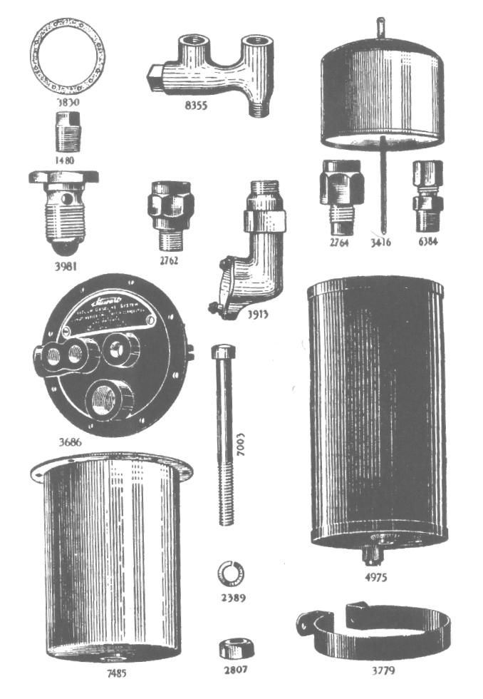
1 T HE Stewart Vacuum Gasoline System employs a small tank, installed under the hood. This tank is connected by brass tubing to the intake manifold, also to gasoline supply tank, and to carburetor. Every motor draws its supply of gasoline through the carburetor by reason of the pumping action of the pistons. It is this same pumping action which draws gasoline from the main supply tank into the Stewart tank, through the connection of the manifold and the Stewart tank, and also the connection of the Stewart tank with the gasoline supply tank. The Stewart Vacuum Gasoline Tank consists of two chambers. The upper one is the filling chamber, and the lower one is the emptying chamber. Between these two chambers is a partition in which is placed a valve. The suction of the pistons on the intake stroke creates a vacuum in the upper chamber, and this vacuum closes the valve between the two chambers, and also sucks or pumps up the gasoline from the main supply tank into this upper chamber. As the gasoline flows into this upper chamber it raises a float valve. When this float valve has risen to a certain point it operates a valve which shuts off the suction and at the same time opens an air valve. This admission of outside air releases the vacuum 2039

2 suction, thus causing the valve leading into the lower chamber to open, and through which the gasoline immediately commences to flow into the lower or emptying chamber. This lower chamber is always open to the outside air, so that nothing can ever prevent the gasoline in this lower chamber from feeding through its connection to the carburetor in a perfect, even, uninterrupted flow. A is the suction valve for opening and closing the connection to manifold and through which a vacuum is extend from the engine manifold to gasoline tank. B is the atmospheric valve, and permits or prevents an atmospheric condition in the upper charmer. When the suction valve A is open and the suction is drawing gasoline from main reservoir, this atmospheric valve B is closed. When the suction valve A is closed then the atmospheric valve B must be open, as an atmospheric condition is necessary in the upper tank in order to allow the fuel to flow through the flapper valve H into the lower chamber. C is pipe connecting tank to manifold of engine. D is pipe connecting vacuum tank to main gasoline supply tank. E is lever to which the two coil springs S are attached. This lever is operated by the movement of the float G. 2

3 F is short lever, which is operated by the lever E, and which in turn operates the valves A and B. G is the float. H is flapper valve in the outlet T. This flapper valve is held closed by the action of the suction whenever the valve A is open, but it opens when the float valve has closed the vacuum valve A and opened the atmospheric valve B. J is pet cock for drawing water or sediment out of reservoir. May also be used for drawing off gasoline for priming or cleaning purposes. K is line to carburetor extended on inside of tank to form pocket for trapping water and sediment, and which may be drawn out through pet cock J. L is channel space between inner and outer shells, and connects with air vent R, thus admitting an atmospheric condition in lower chamber at all times, thereby permitting an even, uninterrupted flow of gasoline to carburetor. M is the guide for float. N is vacuum check valve. P is a line leading to vacuum pump on dash. This vacuum pump, which is installed on the dash, can be used for priming, or for filling the vacuum tank should it ever become empty. It is not necessary to turn over the engine, but merely pull plunger in vacuum pump two or three times, which will create sufficient vacuum in tank to draw gasoline from main supply tank. R is an air vent over the atmospheric valve. Through this tube the lower or reservoir chamber is continually open to atmospheric pressure, so that the flow of gasoline from this lower chamber to the carburetor is always an even, uninterrupted flow. T is the outlet located at the bottom of the float reservoir. 3

4 Leave tank alone. Don't tamper with it. It is not very likely that it will ever be necessary to open the tank, but if it is opened, then follow directions carefully. The simple, durable construction used in the manufacture of the Stewart Vacuum Tank makes it unlikely that the car owner will ever need to make internal repairs. If the instructions for care are carried out, the Stewart Vacuum Gasoline System should continue indefinitely to operate perfectly. Before proceeding to repair vacuum tank, make absolutely sure that the trouble is not due to some other cause. If your vacuum system does not operate satisfactorily, the following suggestions will enable you to make the necessary adjustment : VENT TUBE OVERFLOW. (See R, page 2.) The air vent allows an atmospheric condition to be maintained in the lower chamber, and also serves to prevent an overflow of gasoline in descending steep grades. If once in a long while a small amount of gasoline escapes, no harm will be done and no adjustment is needed. 4
5 However, if the vent tube regularly overflows, it may be found that the air hole in main gasoline tank filler cap is stopped up. If so, clean it out. GASOLINE LEAKAGE. If gasoline leaks from system, except from vent tube, it can only do so from one of the following causes : a. A leak in outer wall of tank may have occurred. If so, soldering up the hole will eliminate trouble. b. Carburetor connection in bottom of tank may be loose. If so, it should be screwed up tight. c. There may be leak in tubing length B or C (see page 4). FAILURE TO FEED GASOLINE TO CARBURETOR. Remember that this condition may be due to other causes than the vacuum system. Do not blame vacuum system until you are sure that the fault does not lie elsewhere. After flooding _the carburetor, or "tickling the carburetor," as it is commonly called, if gasoline runs out of the carburetor float chamber, you may be sure that the vacuum feed is performing its work of feeding the gasoline to carburetor. Another test is to take out the inner vacuum tank, leaving only, the outer shell. If you fill this shell with gasoline and motor still refuses to run properly, then the fault clearly lies elsewhere and not with the vacuum system because you must certainly get gasoline feed from this open, elevated tank of gasoline, unless there is stop-page in the connection line to carburetor. TO REMOVE TOP. In removing top of tank, after taking out screws, run the blade of a knife carefully around top, between cover and body of tank, so as to separate gasket without damaging it. Gasket is shellaced to make an air-tight joint. IF FAULTY FEED IS TRACED TO VACUUM SYSTEM, ONE OF THE FOLLOWING CONDITIONS MAY BE THE CAUSE. a. The float (see G, page 3), which should be air-tight, may have developed a leak ; thus filling up float with gasoline and making it too heavy to rise sufficiently to close vacuum valve. This allows gasoline to be drawn into manifold, which in turn will choke down the motor. Proper operation depends upon the float being air-tight TO REPAIR FLOAT. Remove top of tank (to which float is attached) as above directed. Dip the float into a pan of HOT water, in order to find out definitely where the leak is. Bubbles will be seen at point where leak occurs. Mark this spot. 5
6 Next, punch two small holes, one in the top and the other in the bottom of the float, to permit discharge of the gasoline. Then solder up these holes and the leak. Test the float by dipping in HOT water. If no bubbles are seen, the float is air-tight. In soldering float, be careful not to use more solder than required. Any unnecessary amount of solder will make the float too heavy. In taking out float and repairing it, take care not to bend the float guide rod. If you do bend the rod, it will strike against guide and retard float, producing the same effect as a leaky float, and allowing gasoline to enter manifold. Also note whether surface of rod is perfectly smooth so that it cannot be retarded by guide. To overcome the condition of a leaky float temporarily until you can reach a garage, remove plug W at the top. In some cases the suction of the motor is sufficient to draw gasoline into tank even with this plug open, but not enough to continue to be drawn into manifold. If, however, you are not able to do this, close up plug W with engine running. This will fill tank. After running engine until tank is full remove plug W until gasoline gives out. Continue repeating same operations until a repair station or garage is reached, when the leaky float can be remedied. b. The flapper valve may be out of commission. A small particle of dirt getting under the flapper valve (see H, page 2) might prevent it from seating absolutely air-tight, and there-by render the tank inoperative. In order to determine whether or not the flapper valve is out of commission, first plug up air - vent ; then detach tubing from bottom of tank to carburetor. Start motor and apply finger to this opening. If suction is felt continuously then it is evident that there is a leak in the connection between the tank and the main gasoline supply, or else the flapper valve is being held off its seat and is letting air into the tank, instead of drawing gasoline. In many cases this troublesome condition of the flapper valve can be remedied by merely tapping the side of the tank, thus shaking loose the particle of dirt or lint which has clogged the valve. If this does not prove effective, remove tank cover, as described on previous page. Then lift out the inner tank. The flapper valve will be found screwed into the bottom of this inner tank. c. Manifold connection (see C, page 2) may be loose, allowing air to be drawn into manifold. d. Tubing may be stopped up, in lengths A, B or C (see page 4). e. Gasoline strainer (see V, page 2) is a screen located in the line from gasoline tank. This screen collects all foreign sub-stances that might get in the rear tank and be carried through to the carburetor and clog it. If tank fails to work, it may be that this screen is clogged, preventing gasoline from getting into tank. Screen may be easily cleaned by unfastening connection at elbow. This cleaning should be done every three weeks. if tank should ever fail to operate, examine strainer FIRST. 6
7 INCREASED GASOLINE CONSUMPTION. Vacuum feed should show the same rate of gasoline consumption as gravity feed, and a saving over pressure feed. If such a condition does not result in your car, perhaps the cause is: a. Carburetor may need adjustment. b. Vent tube may overflow. (See "Vent Tube," page 4.) c. There may be a leak in tank or tubing note instructions under "Vent Tube" and "Gasoline Leakage." d. If the motor speeds up when the vacuum tank is drawing gasoline from the main supply, it shows that either your carburetor mixture is too rich, or your connections are so loose that it is drawing air into the manifold. There should be no perceptible change of engine speed when the tank is operating. CARBURETOR TROUBLE. a. Carburetor trouble cannot be attributed to vacuum system. If gasoline is delivered to carburetor, vacuum feed has done its work. b. If carburetor pops and spits, carburetor adjustment is needed. c. If car slows down, or if you cannot get usual speed out of car while running with open throttle, although the car still continues to run, you may be sure the trouble is not due to vacuum system. If all the gasoline in vacuum tank is exhausted the car will stop. FILLING UP TANK IN STARTING. To fill the tank, should it ever become entirely empty, close the engine throttle and turn the engine over a few revolutions. This will create sufficient vacuum in the tank to fill it. If the tank has been allowed to stand empty for a considerable time and it does not easily fill when the engine is turned over, this may be caused by dirt or sediment being under the flapper valve H. Or, perhaps, the valves are dry. Removing the plug W in the top and squirting a little gasoline into the tank will wash the dirt from this valve, and also wet the valves, and cause the tank to work immediately. This flapper valve sometimes gets a black carbon pitting on it, which may tend to hold it from being sucked tight on its seat. In this case the valve should be scraped with a knife. CLEAN TANK EVERY THREE MONTHS. Unless gasoline is filtered through a screen or chamois when filling the main gasoline tank, from which the vacuum tank draws its supply, some dirt or sediment will accumulate in the main tank. Part of this dirt may be drawn into the vacuum tank. This dirt should be removed from the vacuum tank at least once every three months. To clean the tank remove the top of the tank and take out the inner shell or vacuum chamber (note instructions "To Remove Top," on page 5). This will give access to the lower chamber from which the dirt should be removed. (Don't take tank off of car you may not be able to get it back in the same position.) 7
8
9
TILLOTSON LTD., CLASH INDUSTRIAL ESTATE, TRALEE, CO. KERRY, IRELAND PHONE: FAX:
 TILLOTSON LTD., CLASH INDUSTRIAL ESTATE, TRALEE, CO. KERRY, IRELAND PHONE: +353 66 7121911 FAX: +353 66 7124503 e-mail: sales@tillotson.ie SERIES SERVICE MANUAL INTRODUCTION The gasoline engine industry
AN EXPLANATION OF CIRCUITS CARTER YH HORIZONTAL CLIMATIC CONTROL CARBURETER
 AN EXPLANATION OF CIRCUITS CARTER YH HORIZONTAL CLIMATIC CONTROL CARBURETER The Carter Model YH carbureter may be compared with a Carter YF downdraft carbureter with the circuits rearranged to operate
TILLOTSON LTD., CLASH INDUSTRIAL ESTATE, TRALEE, CO. KERRY, IRELAND PHONE: FAX:
 TILLOTSON LTD., CLASH INDUSTRIAL ESTATE, TRALEE, CO. KERRY, IRELAND PHONE: +353 66 7121911 FAX: +353 66 7124503 e-mail: sales@tillotson.ie HU SERIES SERVICE MANUAL INTRODUCTION To keep apace of new market
TILLOTSON LTD., CLASH INDUSTRIAL ESTATE, TRALEE, CO. KERRY, IRELAND PHONE: FAX:
 TILLOTSON LTD., CLASH INDUSTRIAL ESTATE, TRALEE, CO. KERRY, IRELAND PHONE: +353 66 7121911 FAX: +353 66 7124503 e-mail: sales@tillotson.ie HR SERIES SERVICE MANUAL INTRODUCTION Tillotson has developed
TILLOTSON LTD., CLASH INDUSTRIAL ESTATE, TRALEE, CO. KERRY, IRELAND PHONE: FAX:
 TILLOTSON LTD., CLASH INDUSTRIAL ESTATE, TRALEE, CO. KERRY, IRELAND PHONE: +353 66 7121911 FAX: +353 66 7124503 e-mail: sales@tillotson.ie HS SERIES SERVICE MANUAL INTRODUCTION The demand for a miniature
Carburetor Instructions
 Carburetor Instructions for HUDSON SUPER SIX ESSEX SIX CYLINDER Hudson Motor Car Co. DETROIT, U.S.A. Carburetor The carburetor is a device for metering correct amounts of fuel and air for the various
GROUP 3B CLEANER AIR SYSTEM CONTENTS
 3B-0 GROUP 3B CLEANER AIR SYSTEM CONTENTS SECTION 0 GENERAL 1 2. Removal and Installation 3 3 SECTION 1 SUB TANK 2 2-2 Installation 3 2 2-3 Inspection and Maintenance 3 2. Removal and Installation 2 9
Sales : Mobile : The Zenith 24 T-2 carburettor
 The Zenith 24 T-2 carburettor is an up draught carburettor, developed principally for use on your Ferguson TEA20 (Vaaljapie) tractor. It can be supplied in several versions, the main variations being the
COLT 2310, 2510, AND 2712 COM PACT TRACTORS CHAPTER 9 TROUBLESHOOTING AND ANALYSIS
 COLT 2310, 2510, AND 2712 COM PACT TRACTORS CHAPTER 9 TROUBLESHOOTING AND ANALYSIS 9-A-1 UPON RECEIVING ANENGINE FORRE- PAIR. Learn the history of the unit from the customer. While the customer is present
7. Evaporative Emission Control System
 W1860BE.book Page 10 Tuesday, January 28, 2003 11:01 PM 7. Evaporative Emission Control System A: GENERAL The evaporative emission control system prevents fuel vapors from escaping into atmosphere. This
JACKALL HYDRAULIC SYSTEM
 JACKALL HYDRAULIC SYSTEM FIG. 1. Layout of a typical installation. Servicing Instructions for Red Jackall. The Red Jackall hydraulic system requires no attention other than a periodical examination of
INFORMATION. covering use of Ammeter and Voltmeter ON and 1915 Model Six-54 Electrical System
 INFORMATION covering use of Ammeter and Voltmeter ON- 1914 and 1915 Model Six-54 Electrical System Hudson Motor Car Company Detroit, Michigan, IX S. A USE OF AMMETER ON 1914 AND 1915 MODEL SIX-54 With
HUDSON MOTOR CAR COMPANY
 HUDSON MOTOR CAR COMPANY 1935-1942 Carburetor Tune-up Manual ( for Hudson and Terraplane Models) Index Carter W-1 Downdraft 1935-1942 1 Carter W-1 Vacumeter Type 1938 Hudson 4 Carter WA-1 Vacumeter Type
Volumetric Measuring Devices Issued: Revision Number: 2
 Field Inspection Manual Part: 4-STP Section: 29 Page: 1 of 5 APPLICATION This procedure is used when performing accuracy tests on any measuring systems that incorporate an air eliminator or deaerator of
Simple Carburettor Fuel System for a Piston Engine. And how it works
 Simple Carburettor Fuel System for a Piston Engine And how it works Inlet Exhaust Tank PISTON ENGINE Carburettor Fuel System Filler Cap COCKPIT FUEL GAUGE E FUEL 1/2 F Filler Neck Tank Cavity FUEL LEVEL
FUEL AND LUBRICATION SYSTEM
 AND LUBRICATION SYSTEM 4-1 A-PDF Split DEMO : Purchase from www.a-pdf.com to remove the watermark AND LUBRICATION SYSTEM CONTENTS SYSTEM... 4-2 PUMP... 4-2 TANK/ COCK... 4-3 REMOVAL... 4-3 INSPECTION...
INSTALLATION, OPERATION AND MAINTENANCE INSTRUCTIONS
 INSTALLATION, OPERATION AND MAINTENANCE INSTRUCTIONS Contents Section 1. General Observations... 2 2. Operation... 4 3. Control During Operation... 5 4. Trouble Shooting... 6 5. Maintenance... 7 Please
CARTER DOWNDRAFT CARBURETOR Terraplane All Models. Technical Information
 CARTER DOWNDRAFT CARBURETOR 1934 Terraplane All Models Technical Information . Carter W-1 Downdraft Carburetors 1934 Terraplane Challenger, Model KS NOTE: Terraplane Models. Carburetor fitted with Anti-
SECTION 4 - FUEL/LUBRICATION/COOLING
 For Arctic Cat Discount Parts Call 606-678-9623 or 606-561-4983 SECTION 4 - FUEL/LUBRICATION/COOLING 4 TABLE OF CONTENTS Carburetor Specifications... 4-2 Carburetor Schematic... 4-2 Carburetor... 4-3 Cleaning
Body type location. Model number location. Small Engine Parts
 Body type location Model number location Small Engine Parts FUEL PUMP SYSTEM SYSTEMS AND OPERATION The fuel pump on a diaphragm carburetor uses the vacuum and pressure pulse from the engines crankcase
Section 10 Chapter 17
 Section 10 Chapter 17 24 Valve, 8.3 Liter Engine Air Intake System Note: All coding used in the 8.3 Liter and 9 Liter engine manuals are Cummins engine codes. These engine codes have no meaning to New
MASTER COALESCER JR & PORTABLE MASTER COALESCER JR AIR PUMP MODEL INSTALLATION MANUAL
 MASTER COALESCER JR & PORTABLE MASTER COALESCER JR AIR PUMP MODEL INSTALLATION MANUAL INSTALLATION: CHOOSING THE LOCATION: Locate the coalescer as near to the intended point of use as possible. Avoid high
GENERAL DESCRIPTION ROCHESTER 4GC 4-JET CARBURETOR 6B PONTIAC SHOP MANUAL
 6B-56 1955 PONTIAC SHOP MANUAL GENERAL DESCRIPTION ROCHESTER 4GC 4-JET CARBURETOR The Rochester 4GC Carburetor for the 1955 Pontiac V -8 is essentially two 2 -J et carburetors in a single casting. The
Engine Does Not Start or Is Hard to Start Cause of Trouble. 1. Open the drain screw, and check Fuel not supplied (1) Fuel tank empty
 Fuel tank empty") 20. Engine Does Not Start or Is Hard to Start 20-1 Engine Output Insufficient 20-2 Poor Performance at Low Speed and Idling 20-3 Poor Performance at High Speed 20-3 Unsatisfactory Operation 20-4 Fuel Gauge
20. Engine Does Not Start or Is Hard to Start 20-1 Engine Output Insufficient 20-2 Poor Performance at Low Speed and Idling 20-3 Poor Performance at High Speed 20-3 Unsatisfactory Operation 20-4 Fuel Gauge
DESCRIPTION FUEL AND VACUUM PUMP REMOVE AND REPLACE FUEL PUMP-OVERHAUL 6B PONTIAC SHOP MANUAL. S. Install battery and connect cables.
 6B-74 1955 PONTIAC SHOP MANUAL DESCRIPTION FUEL AND VACUUM PUMP All models are equipped with a combination fueland double acting vacuum pump operated by an eccentric bolted to the front end of the engine
Automobile section, showing different parts in detail. and miscellaneous devices.
 SECTION VII Nos. 97 112 Automobile section, showing different parts in detail. and miscellaneous devices. Hydraulic jack MECHANICAL MODELS 43 Section VII 97. Automobile engine starter. This device known
SECTION 3.00 WARNING WARNING ENGINE STARTUP AND SHUTDOWN PRESTART INSPECTION
 SECTION 3.00 ENGINE STARTUP AND SHUTDOWN PRESTART INSPECTION Be sure that the clutch, circuit breaker, or other main power transmission device is disconnected. Generators develop voltage as soon as the
EQUALIZER International Limited 10T(I) Integral Hydraulic Spreading Wedge Repair Instruction Manual
 Integral Hydraulic Spreading Wedge Repair Instruction Manual") EQUALIZER International Limited 10T(I) Integral Hydraulic Spreading Wedge Repair Instruction Manual INDEX THE EQUALIZER 10T(I) Integral Hydraulic Wedge SECTION CONTENTS PAGE NO (S) 03 04 05 06 07 08 09
EQUALIZER International Limited 10T(I) Integral Hydraulic Spreading Wedge Repair Instruction Manual INDEX THE EQUALIZER 10T(I) Integral Hydraulic Wedge SECTION CONTENTS PAGE NO (S) 03 04 05 06 07 08 09
TECH INFORMATION EMPI D Performance 2-Barrel Carburetor
 TECH INFORMATION EMPI D Performance 2-Barrel Carburetor The New EMPI D 2-Barrel Performance Carburetor.Built specifically for the VW Aftermarket. With all the features that you have asked for More Progression
WEBER CARBURETOR TROUBLESHOOTING GUIDE
 This guide is to help pinpoint problems by diagnosing engine symptoms associated with specific vehicle operating conditions. The chart will guide you step by step to help correct these problems. For successful
BS5582 VACUUM PUMP AND BRAKE BLEEDER KIT Instructions
 RELEVANT PRODUCTS OF BRAKE SYSTEM SERVICE Motorcycle Service Tools BS5630 Brake Fluid Tester BS0245 BS5800 Brake Fluid Condition Tester Detaching Tool Motorcycle Service Tools BS9870 30mm Disc Brake Spreader
Trouble Shooting Guide EWA, 3-phase (D2422)
") Trouble Shooting Guide EWA, 3-phase (D2422) Trouble Shooting Guide Problem Possible Cause Possible Remedy Unit does not start Breaker tripped, no power to unit Loose wire Defective contactor or coil Close
Trouble Shooting Guide EWA, 3-phase (D2422) Trouble Shooting Guide Problem Possible Cause Possible Remedy Unit does not start Breaker tripped, no power to unit Loose wire Defective contactor or coil Close
Principals of Operation... 1 Rotary Vane Priming Pump VPE and VPES... 2 Rotary Vane Priming Pump VPO and VPOS Priming Valve...
 Priming Systems Installation Priming Systems Operation & Maintenance Form No. F 1031 Section 2312 Issue Date 10/07/94 Rev. Date 02/27/06 Table of Contents Illustrations Principals of Operation...........................
4. FUEL SYSTEM CK 1 4-0
 4 4 4-0 SERVICE INFORMATION... 4-1 FLOAT LEVEL INSPECTION... 4-5 TROUBLESHOOTING... 4-2 CARBURETOR INSTALLATION... 4-6 THROTTLE VALVE DISASSEMBLY... 4-3 THROTTLE VALVE ASSEMBLY... 4-6 CARBURETOR REMOVAL...
12. CARBURETOR 12-0 CARBURETOR VITALITY 50
 12 12 CARBURETOR SERVICE INFORMATION (2-STROKE)... 12-2 SERVICE INFORMATION (4-STROKE)... 12-3 THROTTLE VALVE (2-STROKE)... 12-5 CARBURETOR (2-STROKE)... 12-7 AIR SCREW ADJUSTMENT (2-STROKE)... 12-13 REED
Petrol Driven Water Pump. Model No. CD1-1 Part No OPERATING & MAINTENANCE INSTRUCTIONS
 Petrol Driven Water Pump Model No. CD1-1 Part No. 7230034 OPERATING & MAINTENANCE INSTRUCTIONS Thank you for purchasing this Clarke CD1 petrol driven water pump. Before attempting to operate this pump
PLUNGER PUMP SERVICE MANUAL
 PLUNGER PUMP SERVICE MANUAL INSTALLATION AND START-UP INFORMATION Optimum performance of the pump is dependant upon the entire liquid system and will be obtained only with the proper selection, installation
Farval. Dualine Installation System Start-Up. Bulletin DL300 BIJUR DELIMON INTERNATIONAL
 Farval Dualine Installation System Start-Up Bulletin DL300 BIJUR DELIMON INTERNATIONAL 2685 Airport Road Kinston, NC 28504 Tel. 800-227-1063 Fax: 252-527-9232 website: www.bijurdelimon.com DC1-1 SECTION
5. FUEL SYSTEM 5-0 FUEL SYSTEM MXU 250R/300R
 5 FUEL SYSTEM 5 SERVICE INFORMATION------------------------------------------------ 5-2 TROUBLESHOOTING----------------------------------------------------- 5-3 FUEL TANK -----------------------------------------------------------------
PLUNGER PUMP SERVICE MANUAL
 PLUNGER PUMP SERVICE MANUAL INSTALLATION AND START-UP INFORMATION Optimum performance of the pump is dependant upon the entire liquid system and will be obtained only with the proper selection, installation
Medium and high pressure pumps
 Screw pumps Medium and high pressure pumps Installation and Start-up Instruction This instruction is valid for all standard high pressure pumps: E4, D4 and D6 Contents Page Pump identification 2 Installation
Purging Air From Divider Block Lubrication Systems
 FROST ENGINEERING SERVICE Purging Air From Lubrication Systems A D I V I S I O N O F G E C S E Y S A L E S & S E R V I C E DESCRIPTION Divider block lubrication systems operate correctly only when all
Types of Carburetors. How they work. This presentation is from Virginia Tech and has not been edited by the Georgia Curriculum Office.
 Types of Carburetors How they work This presentation is from Virginia Tech and has not been edited by the Georgia Curriculum Office. Performance Objectives Students will be able to list and describe the
Table of Contents Illustrations
 Principals of Operation Inspection & Troubleshooting Principles of Operation Inspection & Troubleshooting Form No. F 1031 Section 1000 Issue Date 09/19/94 Rev. Date 02/07/07 Table of Contents Illustrations
INSTALLATION AND OPERATING INSTRUCTIONS FOR CONCRETE VAULT TYPE UNITS
 INSTALLATION AND OPERATING INSTRUCTIONS FOR CONCRETE VAULT TYPE UNITS CONTENTS Introduction Safety Operating Principle System Installation Initial Startup System Operations Troubleshooting Maintenance
FU-1 FUEL SYSTEM. Page PRECAUTIONS... TROUBLESHOOTING... ON-VEHICLE INSPECTION...
 FU-1 FUEL SYSTEM PRECAUTIONS... TROUBLESHOOTING... ON-VEHICLE INSPECTION... CARBURETOR FUEL PUMP... Page FU-2 FU-2 FU-3 FU-4 FU-28 FU-2 FUEL SYSTEM - Precautions, Troubleshooting PRECAUTIONS 1. Before
12. CARBURETOR/FUEL PUMP
 12 CARBURETOR/FUEL PUMP SERVICE INFORMATION... 12-2 TROUBLESHOOTING... 12-2 THROTTLE VALVE DISASSEMBLY... 12-3 THROTTLE VALVE INSTALLATION... 12-4 CARBURETOR REMOVAL... 12-5 AUTO BYSTARTER... 12-6 FLOAT
KEIHIN CARBURATORS FOR 4-CYLINDER HONDA MOTORCYCLES
 KEIHIN CARBURATORS FOR 4-CYLINDER HONDA MOTORCYCLES Set of 4 Keihin carburetors marked 089A and used on 1976 CB550K GENERAL NOTES: All carburetors perform the same function: mixing air and fuel for supply
Version 1.4 Operating instructions Czech Republic
 Version 1.4 Operating instructions Czech Republic Please check updates of operating instructions at www.rotomotor.cz, that your engine has still the best care. (can happen important changes that will lead
WARNING: Do not use pumps for gasoline or highly flammable products! Do not use pumps for water based fluids, solvents or chemicals!
 50:1 Value Line Pneumatic Grease Pump Technical Brief 07/01/2010 No. 18710 201 Fits 35 lb. Pail Premium quality pneumatic pump used for 35 lb. Pail 1.Recommended Usage Grease pumps with a ratio of 50:1
5. FUEL SYSTEM 5-0 FUEL SYSTEM UXV 500
 5 FUEL SYSTEM 5 SERVICE INFORMATION------------------------------------------------ 5-02 TROUBLESHOOTING----------------------------------------------------- 5-03 FUEL TANK -----------------------------------------------------------------
CARBURETOR SERVICE INFORMATION TROUBLESHOOTING THROTTLE VALVE DISASSEMBLY THROTTLE VALVE INSTALLATION...
 11 CARBURETOR SERVICE INFORMATION... 11-2 TROUBLESHOOTING... 11-2 THROTTLE VALVE DISASSEMBLY... 11-3 THROTTLE VALVE INSTALLATION... 11-4 CARBURETOR REMOVAL... 11-5 AUTO BYSTARTER... 11-6 FLOAT CHAMBER...
9.7 Replacement of the compressed air distributor
 9.6.6 9.6.7 screw in the bolt and to increase unscrew the bolt. For a complete rotation of the bolt, the variation is of 1mm. After measuring the pointer position and the compensatory adjustment screw
Water pump Owner's Manual
 Water pump Owner's Manual Safety Precautions I. General Safeguards Please read this operation manual to have a thorough understanding of the content there before use the product. Failure to do so may lead
AIR CLEANER GENERAL REMOVAL. 1CAUTION Do not run engine without filter element in place. Debris could be drawn into the engine causing damage.
 AIR CLEANER GENERAL The air cleaner prevents foreign material from entering the carburetor and engine by trapping airborne dust and dirt in the filter element. Service air cleaner filter element every
Service Instruction ENGINE COMPONENTS, INC.
 Title: Service Instruction S.I. No.: 89-5-1 Page: 1 of 5 Issued: 05/05/89 Revision: 1 (09/01/01) Technical Portions of FAA DER Approved. FAILURE OF ENGINE TO START 27 points 1. Lack of fuel 2. Ignition
EMISSION CONTROL (AUX. EMISSION CONTROL DEVICES) H6DO
 H6DO") EMISSION CONTROL (AUX. EMISSION CONTROL DEVICES) H6DO SYSTEM OVERVIEW 1. System Overview There are three emission control systems, which are as follows: Crankcase emission control system Exhaust emission
EMISSION CONTROL (AUX. EMISSION CONTROL DEVICES) H6DO SYSTEM OVERVIEW 1. System Overview There are three emission control systems, which are as follows: Crankcase emission control system Exhaust emission
ENGINE AND EMISSION CONTROL
 17-1 ENGINE AND EMISSION CONTROL CONTENTS ENGINE CONTROL SYSTEM........ 3 SERVICE SPECIFICATION............... 3 ON-VEHICLE SERVICE.................. 3 Accelerator Cable Check and Adjustment... 3 ACCELERATOR
ZAMA CUBE CARBURETOR DISASSEMBLY AND SERVICE
 ZAMA CUBE CARBURETOR DISASSEMBLY AND SERVICE MIXTURE SCREWS Remove idle and main mix ture screw. Inspect each screw for damage, especially the needle points which should have no deformation of the tapered
EMISSION CONTROL (AUX. EMISSION CONTROL DEVICES) H4DOTC
 H4DOTC") EMISSION CONTROL (AUX. EMISSION CONTROL DEVICES) H4DOTC SYSTEM OVERVIEW 1. System Overview There are three emission control systems, which are as follows: Crankcase emission control system Exhaust emission
EMISSION CONTROL (AUX. EMISSION CONTROL DEVICES) H4DOTC SYSTEM OVERVIEW 1. System Overview There are three emission control systems, which are as follows: Crankcase emission control system Exhaust emission
Use these modules to gain valuable knowledge about STIHL policies, procedures and products that will be a benefit to you on the job immediately.
 Bronze Level Training Lesson 09 This is Bronze Level 09 of 10. Welcome to the Service Advantage Bronze Level Training on icademy. These modules are designed to enhance your knowledge base on topics such
TWO-STAGE HYDRAULIC PUMP. RWP55-IBT-Air
 ORIGINAL INSTRUCTIONS Form No.1000458 5 SPX Corporation 5885 11th Street Rockford, IL 61109-3699 USA Tech. Services: (800) 477-8326 Fax: (800) 765-8326 Order Entry: (800) 541-1418 Fax: (800) 288-7031 Internet
L-l0 Cumins Turbo charged engine needs five minute cool down at idle speed. Wisconsin engine needs five minute cool down at idle speed
 BOOK: Blue Book I SECTION: Ford LTS 9000 Tanker (SGT) Page 1 of 10 TABLE OF CONTENTS FORD LTS 9000 2,500 GALLON TANKER SPECIFICATIONS... 2 IN THE CAB... 3 ON THE CONSOLE... 3 WISCONSIN AUXILIARY PUMP...
13. FUEL SYSTEM/CARBURETOR/
 13 FUEL SYSTEM/CARBURETOR/FUEL PUMP FUEL SYSTEM --------------------------------------------------------- 13-1 SCHEMATIC DRAWING ---------------------------------------------- 13-2 OPERATION OF CARBURETOR
ENGINE AND EMISSION CONTROL
 -1 ENGINE CONTROL.......... GENERAL INFORMATION...... SERVICE SPECIFICATIONS..... ON-VEHICLE SERVICE......... ACCELERATOR CABLE CHECK AND ADJUSTMENT.................... ACCELERATOR CABLE AND PEDAL......................
VS403 INSTRUCTIONS FOR: VACUUM AND PRESSURE TEST / BRAKE BLEEDING UNIT MODEL: SAFETY INSTRUCTIONS INTRODUCTION & CONTENTS. fig.1
 INSTRUCTIONS FOR: VACUUM AND PRESSURE TEST / BRAKE BLEEDING UNIT MODEL: VS403 Thank you for purchasing a Sealey product. Manufactured to a high standard this product will, if used according to these instructions
ENGINE AND EMISSION CONTROL
 17-1 GROUP 17 ENGINE AND EMISSION CONTROL CONTENTS ENGINE CONTROL.......... 17-3 GENERAL INFORMATION...... 17-3 SERVICE SPECIFICATIONS..... 17-3 TROUBLESHOOTING.......... 17-3 INTRODUCTION TO ENGINE CONTROL
ENGINE DRIVEN 3 FULL TRASH PUMP
 ENGINE DRIVEN 3 FULL TRASH PUMP MODEL NO: PF75 PART NO: 7230165 OPERATION & MAINTENANCE INSTRUCTIONS ORIGINAL INSTRUCTIONS LS0117 ISS 2 INTRODUCTION Thank you for choosing this Clarke Pump. The function
Voltmaster Centrifugal Trash Pumps
 Voltmaster Centrifugal Trash Pumps Model TSP2, TSP3 and TSP4 Owner s Manual February 2011 Table of Contents 1 Introduction............................ 1 1.1 Read before using..................... 1 1.2
SECTION AIR INTAKE SYSTEM
 09-500.295/ 1 2007AL05 SECTION 09-500.295 AIR INTAKE Air for the engine is taken in through a grille located on the upper-rear, left-hand side of the vehicle. See Figure 1. Air passes through a chamber,
Operation and Maintenance Instructions for the RAPTOR 178
 WWW.SKYTOY.COM Operation and Maintenance Instructions for the RAPTOR 178 See www.skytoy.com for updates and service bulletins. 2/1/2011 1. Parts Schematic:... 3 2. Muffler Assembly Diagram:... 4 3. Muffler
Troubleshooting the Transmission Hydraulic System
 Testing and Adjusting IT28F INTEGRATED TOOLCARRIER POWER TRAIN Testing And Adjusting Introduction Reference: For Specifications with illustrations, refer to SENR5974, IT28F Integrated Toolcarrier Power
Name Date. True-False. Multiple Choice
 Name Date True-False T F 1. Oil film thickness increases with an increase in oil temperature. T F 2. Displacement is the volume that a piston displaces in an engine when it travels from top dead center
SAFETY AND OPERATING MANUAL
 SAFETY AND OPERATING MANUAL COLD WATER PETROL WATER BLASTERS Read Safety & Operating Instructions Before Commencing Operation THESE INSTRUCTIONS MUST BE READ AND ADHERED TO BEFORE OPERATING THIS MACHINE.
IMPORTANT OPERATING CONDITIONS. Failure to comply with any of these conditions invalidates the warranty. STANDARD CONFIGURATIONS
 X-SERIES TRIPLEX CERAMIC PLUNGER PUMPS OPERATING MANUAL MODELS X8 X10 X20 IMPORTANT OPERATING CONDITIONS Failure to comply with any of these conditions invalidates the warranty. Lubrication - Prior to
Holley High Performance Intake System* For Port 13B Engines (Includes B 6-Port engines converted to 4-Port)
") Holley High Performance Intake System* For 1974-1978 4-Port 13B Engines (Includes 1984-85 13B 6-Port engines converted to 4-Port) Installation Instructions I-18038 Note: These instructions assume: The
Holley High Performance Intake System* For 1974-1978 4-Port 13B Engines (Includes 1984-85 13B 6-Port engines converted to 4-Port) Installation Instructions I-18038 Note: These instructions assume: The
Installation Vertical Pump: Installation 'CM' and 'CDM' Style: Operation:
 Installation Vertical Pump: Gusher vertical end suction pumps with integral shaft is easily installed and put into service. With the one piece shaft design there is no couplings to align, no shims or no
HOW - TO EMISSION CONTROL BASICS EMISSION CONTROL BASICS
 HOW - TO EMISSION CONTROL BASICS EMISSION CONTROL BASICS Tool And Material Checklist Bore Brush Thermometer Portable Vacuum Pump Screwdriver Combination Wrench Set 3/8 Drive Socket Set Tachometer Rag Service
PIERBURG. Carburetor: 2E3
 PIERBURG Carburetor: 2E3 1 fast idle adjusting screw 2 throttle lever 3 fuel mixture adjusting screw 4 main body 5 idle cut off valve 6 stop screw 7 accelerator pump cover 8 diaphragm 9 spring 10 valve
GOLF, TURF AND SPECIALTY PRODUCTS SERVICE MANUAL CARBURETED SUZUKI 970 CC ENGINE. Part No
 GOLF, TURF AND SPECIALTY PRODUCTS SERVICE MANUAL CARBURETED SUZUKI 970 CC ENGINE Part No. 4115757 250 10 99 CU 20001Textron Inc. Lincoln, Nebraska All Rights Reserved. Printed in U.S.A. SECTION TABLE OF
June14. Type
 June14 Type 1. ASSUMPTION ENGLISH HAZARD! Do not touch the plug with wet hands! Switch off and unplug the pump before any maintenance. Please read these instructions carefully before use. Damages resulting
Instruction Model 18537
 Instruction 738-556 Model 18537 LIMITED WARRANTY H. D. Hudson Manufacturing Company warrants to the original purchaser only that this product will continue to function as intended if used in accordance
Fairbanks-Morse Magneto
 Fairbanks-Morse Magneto SECTION VI Ignition System 6-1 GENERAL DESCRIPTION a. MAGNETO - The magneto is an electrical generating device designed to produce controlled electric-spark discharges. These discharges,
A SYSTEMATIC SEQUENCE FOR PM INSPECTIONS
 A SYSTEMATIC SEQUENCE FOR PM INSPECTIONS TYPE OF INSPECTION UNDER THE HOOD GASOLINE AND DIESEL 1 Fuel, oil, exhaust leaks - inspect 2 Oil and fuel lines inspect for kinks and wear 3 Automatic transmission
Instructions for Installation, Operation Care and Maintenance
 Model A Dry Pipe Valve Bulletin 353 Rev.K Bulletin 353 Rev.K Instructions for Installation, Operation Care and Maintenance 2 1 2 (65mm) Valve With Model A Trim Listed by Underwriters Laboratories, Inc.
OWNER S TECHNICAL MANUAL
 OWNER S TECHNICAL MANUAL 2.5kg Grease Kit 6336 Description The Champion 6336 2.5kg grease kit is a manually operated, spring powered grease kit that comes complete with a hand piece. It is designed to
EP1306N 5 Gallon Can Extruder System Rev. A June EP1306N Operation Manual
 EP1306N Operation Manual 1 THIS PAGE HAS BEEN INTENTIONALLY LEFT BLANK 2 TABLE OF CONTENTS SECTION 1: SAFETY... 4 1. GENERAL SAFETY... 5 2. PUMP SAFETY... 5 3. FLUID PRESSURE AND COMPATIBILITY... 6 4.
OWNER S TECHNICAL MANUAL. 6336N 2.5kg Grease Kit
 OWNER S TECHNICAL MANUAL 6336N 2.5kg Grease Kit 6336N Description The 6336N 2.5kg grease kit is a manually operated, spring powered grease kit with ergonomic, user friendly rod cap that comes complete
Technical Data TYPE A SERIES AIR ADJUSTED PILOT SPENCE ENGINEERING COMPANY, INC. 150 COLDENHAM ROAD, WALDEN, NY SD 4011 OPERATING PRINCIPLE
 Technical Data SD 4011 SPENCE ENGINEERING COMPANY, INC. 150 COLDENHAM ROAD, WALDEN, NY 12586-2035 TYPE A SERIES AIR ADJUSTED PILOT PRINTED IN U.S.A. SD 4011/9504 Type A or A83 (wt 6 lb) Type A53 or A 85
FUEL SYSTEM/CARBURETOR/FUEL PUMP
 13 FUEL SYSTEM/CARBURETOR/FUEL PUMP FUEL SYSTEM-------------------------------------------------------------------------------------13-1 SCHEMATIC DRAWING-------------------------------------------------------------------------13-2
Troubleshooting:Passenger Car
 Troubleshooting:Passenger Car Troubleshooting If the engine or other parts has the problem, it is possible to break the exchange turbocharger again. Please confirm the notes below and inspect each part
EMISSION CONTROL (AUX. EMISSION CONTROL DEVICES) H4SO
 H4SO") EMISSION CONTROL (AUX. EMISSION CONTROL DEVICES) H4SO SYSTEM OVERVIEW 1. System Overview There are three emission control systems, which are as follows: Crankcase emission control system Exhaust emission
EMISSION CONTROL (AUX. EMISSION CONTROL DEVICES) H4SO SYSTEM OVERVIEW 1. System Overview There are three emission control systems, which are as follows: Crankcase emission control system Exhaust emission
4. FUEL SYSTEM 4-0 FUEL SYSTEM NEXXON 50
 4 FUEL SYSTEM SERVICE INFORMATION ------------------------------------------------ 4-2 TROUBLESHOOTING----------------------------------------------------- 4-3 AIR CLEANER REMOVAL -----------------------------------------------
Operating and Maintenance Manual for Type S Flowmeters. M101 Rev. B Type S Flowmeters: 5 8, 3 4 and 1 with 157 & 600 Series Registers
 Operating and Maintenance Manual for Type S Flowmeters M101 Rev. B Type S Flowmeters: 5 8, 3 4 and 1 with 157 & 600 Series Registers TABLE OF CONTENTS Installation & Operation... Page 1 Calibration...
Module 6: Air Foundation Brakes
 Air Brakes Terms and Definitions Basic Components That Make Up Air Foundation Brakes Types of Air Foundation Brakes Parts of a Cam Foundation Brake Parts of a Wedge Foundation Brake Parts of a Disc Foundation
Propane Conversion Systems. Installation Instructions: 2S-LIFAN200TM 2S-LIFAN200FM 2S-LIFAN390TM 2S-LIFAN390FM
 Propane Conversion Systems Installation Instructions: 2S-LIFAN200TM 2S-LIFAN200FM 2S-LIFAN390TM 2S-LIFAN390FM SAFETY FIRST PLEASE READ THE ENTIRE INSTRUCTION PROCEDURE AND SAFETY INFOR- MATION BEFORE ATTEMPTING
SERVICE INSTRUCTIONS D TON
 1120 SOUTH CRYSTAL AVE * BENTON HARBOR MI PH: 269-925-7777 FAX: 269-925-6656 SERVICE INSTRUCTIONS D-51223 4 TON TO ASSEMBLE: 1. Check the handle set screw for tightness. CUSTOMER PRE-USE INSTRUCTIONS THE
MAINTENANCE MANUAL FOR THERMOSTATIC TEMPERATURE REGULATING VALVE TRAC STYLE P
 MANUAL NUMBER P-EFS-1 MAINTENANCE MANUAL FOR THERMOSTATIC TEMPERATURE REGULATING VALVE TRAC STYLE P TRAC Regulator Company Inc. 160 South Terrace Avenue Mount Vernon, New York USA 10550-2408 Phone: (914)
Typical Install Instructions
 Typical Install Instructions Read & understand all steps of these instructions before beginning this installation. WEBER Conversion Kit, VW T-1/2, up to 1835cc 32 / 36 DFEV Weber Carburetor These instructions
Catalytic Failures. Engine running too hot.
 Catalytic Failures It is not uncommon for technicians to misdiagnose a driveability or emissions issue by blaming the converter. In many cases, it s not the converter s fault, but rather one of the engine