BS5582 VACUUM PUMP AND BRAKE BLEEDER KIT Instructions
|
|
|
- Stephen Grant
- 6 years ago
- Views:
Transcription


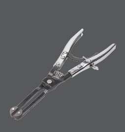


1 RELEVANT PRODUCTS OF BRAKE SYSTEM SERVICE Motorcycle Service Tools BS5630 Brake Fluid Tester BS0245 BS5800 Brake Fluid Condition Tester Detaching Tool Motorcycle Service Tools BS mm Disc Brake Spreader APO TOOL INTERNATIONAL LTD. No.38 Ping An St, Changhua. Taiwan T: / F: Website : service@bikeservice.com.tw BS mm Disc Brake Spreader Represent. BS5582 VACUUM PUMP AND BRAKE BLEEDER KIT Instructions
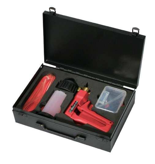
2 FEATURE Designed to assists in locating and identifying system faults. Applications include fuel, ignition, transmission, emissions, clutch bleeding and engine mechanical condition. The manual pump with pressure gauge also allows testing of many vacuum operated systems. Supplied complete with three connector sizes for cars, commercial vehicles and motorcycles. Die cast body with gauge and accessory kit. Easily dismantled for cleaning. Supplied in metal case. INTRODUCTION The use of a vacuum gauge is so often overlooked when determining mechanical condition and carrying out fault diagnosis on internal combustion engines. Monitoring actual manifold vacuum is invaluable when troubleshooting engine faults. This can only be done using a good quality vacuum gauge coupled with a hand-operated vacuum pump, It allows static testing of all types of vacuum operated systems. Set out on following pages are the applications that the vacuum pump can be used. It must always be remembered that these are examples only and reference to manufacturers repair manuals should always be made for correct testing procedures and specifications. In addition to this, it is always recommended that additional tests be conducted such as. Compression tests, Cylinder leakage tests, Ignition timing checks etc, be carried out to confirm indications of vacuum gauge readings.the kit includes case, Vacuum pump, 120ml fluid reservoir, tubing and various adaptors for brake bleeding. The hand operated pump creates a vacuum which rapidly pulls the fluid through the system via the bleed nipple into the fluid reservoir, eliminating the need to use the brake lever or pedal. Easy to use as the stored vacuum created in the reservoir allows both hands free to work on the bleed nipple and spanner. As it is a vacuum drawing the fluid, as opposed to pressure pushing it and eliminates the brake fluid finding its way out round the threads of the nipple or leaking out of the pipe. So much easier and cleaner. Perfect not only for bleeding, but also for replacing old fluid in the system with new. Important on all ABS equipped vehicles. Perfect for use on cars as well as bikes. Where as you might normally avoid stripping your calliper down because bleeding it afterwards is such a nightmare - this makes it ridiculously easy. Even on systems notoriously difficult to bleed. You will be amazed at the difference in your brakes just by servicing your callipers


 Fluid Reservoir.")
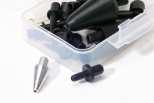
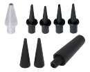
 7mm, (Length) 7cm. 16pc tubes adaptor and hose fittings in case. 7mm 6mm 5mm 31 mm suface suction adaptor. 8.5 mm x 25mm cone suction adaptor.")
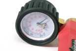
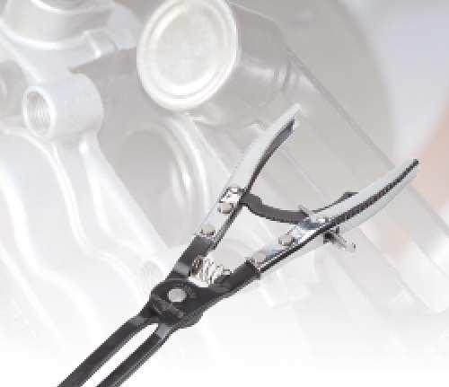
3 TESTING THERMAL VACUUM SWITCHES COMPONENT IDENTIFICATION There are many vacuum controlled circuits that must only operate when the engine reaches normal operating temperature. This is done using thermal switches that remain in an 'off' position until a given To Manifold Vacuum temperature is reached. To test this type of switch, remove the vacuum supply line coming from the manifold to the switch and test for manifold vacuum. If this vacuum is correct refit the supply line to the thermal switch and remove the opposing line from the switch. Attach the unit to the port and start the engine. With a cold engine no reading should be noted. When the engine reaches normal operating temperature manifold vacuum reading should be noted. A F C D E B TESTING VACUUM OPERATED HEATER TAPS Climate control ventilation systems are becoming very common on late model motorcycle and most of the systems use vacuum operated taps to control the heating modes. On the majority of makes and models, the system uses vacuum to turn the heater tap 'on'. To test these remove the supply line from the tap vacuum module and connect the Vacuum Pump. With the engine at normal operating temperature locate and feel the heater return hose. With the heater tap in the 'off' position, this hose should be cold. Now operate the vacuum pump to open the tap. The gauge reading must hold. If the tap is in working order, the return hose will begin to heat. If the hose does not begin to heat this indicates that the tap is faulty. Contents: A B C D E F Vacuum pump and gauge. (76 cm/hg, 30 inch/hg) Fluid Reservoir. (120 ml / 4 oz) 2pc extension tubes. (I.D.) 5mm, (O.D.) 8mm, (Length) 50cm. Extension tubes. (I.D.) 5mm, (O.D.) 8mm, (Length) 10cm. Extension tubes. (I.D.) 4mm, (O.D.) 7mm, (Length) 7cm. 16pc tubes adaptor and hose fittings in case. 7mm 6mm 5mm 31 mm suface suction adaptor. 8.5 mm x 25mm cone suction adaptor. 3pc brake bleeder fittings,for brake adaptor. 2pc suction adaptor. 8.5mm x 25mm cone suction adaptor is used for port in engine or inner structure. 31mm surface suction adaptor is used for surface on engine or other surface structure. 11pc hose cone fitting, used 4mm - 12mm hose and tube connectors


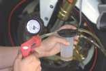
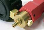
4 Brake Bleeding Assembly Ensure that vacuum pump is connected to the brake bleeder reservoir in accordance with the assembly diagram (Pictured left). Failure to do so will result in brake fluid being drawn into the vacuum pump. BRAKING SYSTEM WORKING Brake Bleeding If bleeding is to be done by one person with a hand vacuum pump type bleeder, perform the following. A. Position the vacuum pump, appropriate size wrench for the bleeder screw, and catch rags at the caliper and remove the rubber boot from the brake bleeder. B. Connect the vacuum pump to the tip of the brake bleeder. Find the adaptor that will provide a tight seal on the brake bleeder. C. Pump the vacuum pump about 10 times and open the brake bleeder. Operate vacuum pump until approximately 21 in/hg vacuum is created in container. D. As fluid comes out of bleeder into the container, continue to pump the vacuum pump, until clean brake fluid starts to come out of the bleed screw. E. If the container fills prior to getting clean fluid, stop bleeding by closing the bleeder and empty the vacuum pump container and start bleeding again. F. When clean fluid comes out of the bleed screw, close the bleed screw. G. Wipe up any spilled brake fluid with a rag. TESTING ELECTRICALLY OPERATED VACUUM SOLENOIDS Electrically operated vacuum solenoids are commonly used in control circuits for air conditioning / ventilation systems, emission control systems, idle step up systems etc and the function testing of these is extremely simple. Locate the solenoid to be tested and remove the line that goes to the component being tested. Connect to the solenoid port and start the engine. With the system turned off there should be a zero gauge reading. Now turn the system to the 'on' position and a gauge reading equal to the manifold vacuum should be noted. If no reading exists remove the vacuum supply line. If the vacuum does exist this indicates that the solenoid is faulty or it is not receiving a 'switch on' voltage (use a multimeter to test this). If no vacuum exists trace the supply line back to the vacuum source checking for kinks and breaks. TESTING EMISSION CONTROL EXHAUST GAS RECIRCULATION VALVES [EGR] Start engine and run at idle until normal operating temperature is reached. Remove the vacuum line from the EGR valve and attach to the Vacuum Pump. Operate the hand pump to apply approximately 15 in/hg. If the EGR Valve is working correctly the engine idle will become rough. If the idle remains unchanged the valve is possibly seized in the closed position. If the vacuum is not held, the diaphragm in the valve is fractured. TESTING ONE WAY VALVES Many vacuum operated circuits use in line one way valves to apply vacuum in one direction only. To test the function of the valve remove it from the circuit. Attach the Vacuum Pump and operate to apply vacuum. In one direction the valve must hold vacuum and in the opposite direction it must not

5 Testing fuel injection pressure regulator Multi point fuel injection rail pressure must vary to suit changing engine loads and fuel delivery requirements. This is done using a vacuum operated regulator which is connected to the engine manifold vacuum to sense the varying loads. To test the fuel rail pressure, a gauge is attached to the rail, then engine loads must be created to vary engine manifold vacuum. Simply remove and block off the vacuum supply line to the pressure regulator, connect and operate the vacuum pump to simulate vacuum pressures in accordance with the manufacturers specifications and note any variation in fuel pressure reading. Note Refer to specific procedures and instructions from the motorcycle manufacturers service manual. Once the bleeder is opened the person holding the brake will feel the pedal go to the floor. This is perfectly normal and they should NOT remove their foot from the pedal until directed to do so by the person doing the bleeding. If they release the brake while the bleeder is open, air will be drawn into the brake system making it more difficult to vent. Empty bleeder container as required. Do not allow the container to overfill as brake fluid will be drawn into vacuum pump. After bleeding, test brake performance. Clean bleeder components with water only after use. IGNITION SYSTEM VACUUM ADVANCE On standard points and some electronic ignition systems there are two types of advance methods used, both of which must function correctly to obtain maximum performance and fuel economy. The first method is Mechanical or Centrifugal, which operates by the use of weights located in the base of the distributor. The weights throw outwards advancing ignition timing as engine RPM increases. This is tested by firstly removing the vacuum advance line to disable the system, then with a timing light connected run the engine RPM up checking that the timing advances in accordance with the manufacturers specification. Testing Brake Booster Diaphragm Remove the vacuum supply line from brake booster fitting. Attach the vacuum pump to vacuum supply port on booster. Operate pump to create approximately 15 in/hg in vacuum booster and allow to sit for 30 seconds. No vacuum drop should be noted on the gauge reading. If the vacuum drops this indicates that the brake booster diaphragm is faulty. In this case the booster should be removed for overhaul by an authorised repairer or replaced. The second method is Vacuum Advance, which senses engine load via manifold vacuum. A vacuum diaphragm is mounted onto the distributor and connected to a rotating internal base plate which advances or retards timing as required to suit varying engine loads. To test this system for correct operation again with the timing light connected raise the engine RPM and check timing advance against manufacturer specifications. In the event that the vacuum advance is not operating, remove the vacuum line from the distributor advance mechanism. Connect the Pump and create a 5-10 inch vacuum, monitoring the timing at the same time. If a timing advance is noted this confirms that the vacuum diaphragm and mechanical links are in order and the fault is a vacuum supply. To confirm this connect to the vacuum supply line and check the gauge reading. No vacuum should be noted at idle but when the engine RPM is increased a vacuum increase should also be noted. If this does not occur, trace the vacuum line back checking for restrictions and breaks


6 ANALYSING ENGINE MECHANICAL CONDITION A. Run engine until normal operating temperature is reached. B. Locate and connect the vacuum gauge to a port directly on the manifold or on the carburettor below the throttle butterfly. C. Start and run the engine at idle, observing the gauge needle reading. The following are readings that may be noted and causes FUEL SYSTEMS Testing mechanical fuel pumps The pump can be used to evaluate the condition of mechanical fuel pumps being tested by the vacuum that it is able to create. Locate and remove the suction line from the pump. Connect to the suction port of the pump, start and run the engine at idle. The vacuum reading that should be noted will vary slightly on different makes and models but as a general rule approximately 15 in/hg should be created. This should also be held for approximately 1 minute after engine shut down. If this vacuum reading is not achieved or the vacuum drops off immediately with the engine shut down, the fuel pump requires either overhaul or replacement. Carburettors There are many different types of vacuum control systems used on carburettors. Using the pump, allows quick and accurate testing of these systems. Listed below are just two examples of tests that can be carried out. READING:16-21 in/hg with needle. steady CAUSE:Normal. READING: When the throttle is suddenly opened then released, the needle should drop to below 5 in/hg then bounce up to approximately 25 in/hg setting back to original reading. CAUSE: Normal. READING: Reading extremely low but steady. CAUSE: Leaking intake manifold system. Faulty manifold gasket, carburettor base gasket, split vacuum hose, seized open EGR value, etc. READING: Reading low but steady. CAUSE: Retarded ignition timing. Confirm using timing light and reset to manufacturers specification. READING: Reading slightly low and fluctuaing slowly. CAUSE: Over lean or rich mixture. Check and reset in accordance to manufacturers specifications. Example 1 Testing a Choke Break Diaphragm. With the engine at normal operating temperature but not running, disconnect the vacuum line to the diaphragm module. Connect the pump and apply approximately 15 in/hg and allow to sit for 30 seconds. No drop in gauge reading should be noted. With the vacuum still applied ensure that the choke butterfly is pulled to the fully open position. READING:Regular fluctuation between normal and low readings. CAUSE:Blown head gasket between two adjacent cylinders carry out cylinder leakage test. READING: Readings slightly lower than for normal engine including when throttle is suddenly opened then released. CAUSE: Wom piston rings. Carry out compression test. READING: Regular drop between normal and low reading. CAUSE: Bumt valve. Note READING: Normal when first started but drops rapidly with RPM held at 3,000. CAUSE: Restriction in exhaust system. The needle readings shown above, are examples only of what may be noted. It is important to remember the action of the needle rather than the actual reading, as varying engine types will run different manifold vacuum pressures, specified on camshaft profile, valve overlap, timing etc, so an exact good vacuum reading cannot be specified. The main thing is that the needle reading is between 16 to 21 in/hg and steady. Manifold vacuum is also affected by altitude with the general rule being that it will drop approximately 1 in/hg for every thousand feet above sea level so this also must be considered when assessing manifold vacuum actual readings. Example 2 Testing Vacuum Operated Carburettor Secondary Barrel. With the engine at normal operating temperature but not running, remove the vacuum line from the secondary diaphragm module. Attach the pump, hold the throttle and secondary air valve flaps open. Operate the hand pump whilst observing free and easy opening of the secondary throttle butterfly
VS403 INSTRUCTIONS FOR: VACUUM AND PRESSURE TEST / BRAKE BLEEDING UNIT MODEL: SAFETY INSTRUCTIONS INTRODUCTION & CONTENTS. fig.1
 INSTRUCTIONS FOR: VACUUM AND PRESSURE TEST / BRAKE BLEEDING UNIT MODEL: VS403 Thank you for purchasing a Sealey product. Manufactured to a high standard this product will, if used according to these instructions
INSTRUCTIONS FOR: VACUUM TESTER AND BRAKE BLEEDING KIT
 INSTRUCTIONS FOR: VACUUM TESTER AND BRAKE BLEEDING KIT MODEL: VS402 Thank you for purchasing a Sealey product. Manufactured to a high standard this product will, if used according to these instructions
INSTRUCTIONS FOR: VACUUM TESTER AND BRAKE BLEEDING KIT. MODEL No. VS4021.V2 1. SAFETY 2. INTRODUCTION 3. CONTENTS
 INSTRUCTIONS FOR: VACUUM TESTER AND BRAKE BLEEDING KIT MODEL No. VS4021.V2 Thank you for purchasing a Sealey product. Manufactured to a high standard, this product will, if used according to these instructions,
Original Language Version VS4021 Issue: 1-08/06/12
 1. safety instructions Keep this product in good working order and condition, take immediate action to repair or replace damaged parts. Use approved parts only. Unapproved parts will invalidate the warranty.
Typical Install Instructions
 Typical Install Instructions Read & understand all steps of these instructions before beginning this installation. WEBER Conversion Kit, VW T-1/2, up to 1835cc 32 / 36 DFEV Weber Carburetor These instructions
WEBER CARBURETOR TROUBLESHOOTING GUIDE
 This guide is to help pinpoint problems by diagnosing engine symptoms associated with specific vehicle operating conditions. The chart will guide you step by step to help correct these problems. For successful
PIERBURG. Carburetor: 2E3
 PIERBURG Carburetor: 2E3 1 fast idle adjusting screw 2 throttle lever 3 fuel mixture adjusting screw 4 main body 5 idle cut off valve 6 stop screw 7 accelerator pump cover 8 diaphragm 9 spring 10 valve
5. FUEL SYSTEM 5-0 FUEL SYSTEM MXU 250R/300R
 5 FUEL SYSTEM 5 SERVICE INFORMATION------------------------------------------------ 5-2 TROUBLESHOOTING----------------------------------------------------- 5-3 FUEL TANK -----------------------------------------------------------------
A. Perform a vacuum gauge test to determine engine condition and performance.
 ENGINE REPAIR UNIT 2: ENGINE DIAGNOSIS, REMOVAL, AND INSTALLATION LESSON 2: ENGINE DIAGNOSTIC TESTS NOTE: Testing the engine s mechanical condition is required when the cause of a problem is not located
4. FUEL SYSTEM CK 1 4-0
 4 4 4-0 SERVICE INFORMATION... 4-1 FLOAT LEVEL INSPECTION... 4-5 TROUBLESHOOTING... 4-2 CARBURETOR INSTALLATION... 4-6 THROTTLE VALVE DISASSEMBLY... 4-3 THROTTLE VALVE ASSEMBLY... 4-6 CARBURETOR REMOVAL...
Honda Accord/Prelude
 Honda Accord/Prelude 1984-1995 In Tank Fuel Pumps TEST 1. Turn the ignition OFF. 2. On the Accord, remove the screws securing the underdash fuse box to its mount. Remove the fuel cut off relay from the
TILLOTSON LTD., CLASH INDUSTRIAL ESTATE, TRALEE, CO. KERRY, IRELAND PHONE: FAX:
 TILLOTSON LTD., CLASH INDUSTRIAL ESTATE, TRALEE, CO. KERRY, IRELAND PHONE: +353 66 7121911 FAX: +353 66 7124503 e-mail: sales@tillotson.ie SERIES SERVICE MANUAL INTRODUCTION The gasoline engine industry
5. FUEL SYSTEM 5-0 FUEL SYSTEM UXV 500
 5 FUEL SYSTEM 5 SERVICE INFORMATION------------------------------------------------ 5-02 TROUBLESHOOTING----------------------------------------------------- 5-03 FUEL TANK -----------------------------------------------------------------
(P0135/P0155), (P0141/P0161), (P1131/P1151), (P1132/P1152). To further clarify this, see the more detailed scenario as follows:
, (P0141/P0161), (P1131/P1151), (P1132/P1152). To further clarify this, see the more detailed scenario as follows:") 1. Always reset KAM after performing a repair: After performing a repair on a vehicle with the MIL on, and/or DTCs present, always clear KAM. When a malfunction is present, the PCM adapts (attempts to
1. Always reset KAM after performing a repair: After performing a repair on a vehicle with the MIL on, and/or DTCs present, always clear KAM. When a malfunction is present, the PCM adapts (attempts to
PicoScope. Do you ever wish you could see inside? Consider our WPS500X pressure transducer as an X-ray machine for your engine
 PicoScope Do you ever wish you could see inside? With Pico Technology s WPS500X pressure transducer you can diagnose: No start Loss of power Misfire Stalling Engine noise Emissions fault Backfire Consider
Catalytic Failures. Engine running too hot.
 Catalytic Failures It is not uncommon for technicians to misdiagnose a driveability or emissions issue by blaming the converter. In many cases, it s not the converter s fault, but rather one of the engine
Rover SD1 Efi System Fuel Supply Components - Explanation and Testing of the Fuel Pump, Filter and Fuel Pressure Regulator
 Rover SD1 Efi System Fuel Supply Components - Explanation and Testing of the Fuel Pump, Filter and Fuel Pressure Regulator Introduction Some of the notes here are repetitious in order to review the components
Notice: Refer to Adding Fluid to the Brake System Notice in the Preface section.
 Page 1 of 6 2008 Pontiac G8 G8 Service Manual Brakes Disc Brakes Repair Instructions Document ID: 2065646 Front Disc Brake Pads Replacement Removal Procedure Tools Required J 23738-A Hand Vacuum Pump.
Name Date. True-False. Multiple Choice
 Name Date True-False T F 1. Oil film thickness increases with an increase in oil temperature. T F 2. Displacement is the volume that a piston displaces in an engine when it travels from top dead center
Parking brake Mechanical brake acting on rear wheels
 11 Brake System 11.1 General SPECIFICATIONS EJTC0010 Master cylinder Type Tandem type I.D. mm(in.) 20.64 mm (0.813 in.) Fluid level warning sensor Provided Brake booster Type Vacuum Boosting ratio 4.0
CARBURETOR SERVICE INFORMATION TROUBLESHOOTING THROTTLE VALVE DISASSEMBLY THROTTLE VALVE INSTALLATION...
 11 CARBURETOR SERVICE INFORMATION... 11-2 TROUBLESHOOTING... 11-2 THROTTLE VALVE DISASSEMBLY... 11-3 THROTTLE VALVE INSTALLATION... 11-4 CARBURETOR REMOVAL... 11-5 AUTO BYSTARTER... 11-6 FLOAT CHAMBER...
12. CARBURETOR/FUEL PUMP
 12 CARBURETOR/FUEL PUMP SERVICE INFORMATION... 12-2 TROUBLESHOOTING... 12-2 THROTTLE VALVE DISASSEMBLY... 12-3 THROTTLE VALVE INSTALLATION... 12-4 CARBURETOR REMOVAL... 12-5 AUTO BYSTARTER... 12-6 FLOAT
ENGINE AND EMISSION CONTROL
 17-1 GROUP 17 ENGINE AND EMISSION CONTROL CONTENTS ENGINE CONTROL.......... 17-3 GENERAL INFORMATION...... 17-3 SERVICE SPECIFICATIONS..... 17-3 TROUBLESHOOTING.......... 17-3 INTRODUCTION TO ENGINE CONTROL
TILLOTSON LTD., CLASH INDUSTRIAL ESTATE, TRALEE, CO. KERRY, IRELAND PHONE: FAX:
 TILLOTSON LTD., CLASH INDUSTRIAL ESTATE, TRALEE, CO. KERRY, IRELAND PHONE: +353 66 7121911 FAX: +353 66 7124503 e-mail: sales@tillotson.ie HR SERIES SERVICE MANUAL INTRODUCTION Tillotson has developed
Test and adjustment values. DTC memory DTC text Possible cause/note Remedy
 AD07.51-P-4000A Fuel injection and ignition system (HFM-SFI) diagnosis, DTC memory 27.2.97 ENGINE 111 a b c d e a b c a b c d Check and adjust engine Fuel injection and ignition system (HFM-SFI) - diagnosis,
BRAKE SYSTEM Article Text 1996 Toyota RAV4 For Copyright 1998 Mitchell Repair Information Company, LLC Wednesday, September 13, :30PM
 Article Text ARTICLE BEGINNING 1996 BRAKES Toyota - Disc & Drum RAV4 * PLEASE READ THIS FIRST * WARNING: For warnings and procedures regarding vehicles equipped with Anti-Lock Brake Systems (ABS), see
11. CARBURETOR 11-0 CARBURETOR ZX / SCOUT 50
 11 CARBURETOR SERVICE INFORMATION... 11-2 TROUBLESHOOTING... 11-2 THROTTLE VALVE DISASSEMBLY... 11-3 THROTTLE VALVE INSTALLATION... 11-4 CARBURETOR REMOVAL... 11-5 AUTO BYSTARTER... 11-6 FLOAT CHAMBER...
Caution: Refer to Adding Fluid to the Brake System Caution in the Preface section.
 Page 1 of 6 2009 Pontiac G8 G8 Service Manual Brakes Disc Brakes Repair Instructions Document ID: 2094891 Rear Disc Brake Pads Replacement Special Tools J 23738-A Hand Vacuum Pump. Removal Procedure Warning:
Vacuum Readings for Tuning and Diagnosis
 Vacuum Readings for Tuning and Diagnosis -Henry P. Olsen Once you learn to properly interpret its readings, a vacuum gauge can be one of the most useful tools in your toolbox. 22 FEATURE Some people consider
Fuel and exhaust systems 4A 21
 Fuel and exhaust systems 4A 21 15.40 Unscrew the union nuts and disconnect the fuel feed and return hoses from the manifold 41 Disconnect the injector wiring harness connector and the vacuum hose from
1999 Toyota RAV BRAKES Disc & Drum - Trucks & Vans
 DESCRIPTION & OPERATION 1999-2000 BRAKES Disc & Drum - Trucks & Vans WARNING: For warnings and procedures regarding vehicles equipped with Anti-Lock Brake Systems (ABS), see appropriate ANTI-LOCK article.
ENGINE AND EMISSION CONTROL
 -1 ENGINE CONTROL.......... GENERAL INFORMATION...... SERVICE SPECIFICATIONS..... ON-VEHICLE SERVICE......... ACCELERATOR CABLE CHECK AND ADJUSTMENT.................... ACCELERATOR CABLE AND PEDAL......................
CARBURETOR P/N , C, S, & CT INSTALLATION, TUNING, AND ADJUSTMENT MANUAL 199R7950-7
 CARBURETOR P/N 0-7448, 0-4412C, 0-4412S, & 0-4412CT INSTALLATION, TUNING, AND ADJUSTMENT MANUAL 199R7950-7 NOTE: These instructions must be read and fully understood before beginning installation. If this
HE Stewart Vacuum Gasoline System employs a small tank, installed under the hood. This tank is connected by brass tubing to the intake manifold, also
 T HE Stewart Vacuum Gasoline System employs a small tank, installed under the hood. This tank is connected by brass tubing to the intake manifold, also to gasoline supply tank, and to carburetor. Every
Diagnostic Trouble Code (DTC) memory, checking and erasing
 memory, checking and erasing") Page 1 of 49 01-12 Diagnostic Trouble Code (DTC) memory, checking and erasing Check DTC Memory (function 02) - Connect VAS5051 tester Page 01-7 and select vehicle system "01 - Engine electronics". Engine
Page 1 of 49 01-12 Diagnostic Trouble Code (DTC) memory, checking and erasing Check DTC Memory (function 02) - Connect VAS5051 tester Page 01-7 and select vehicle system "01 - Engine electronics". Engine
Brake Bleeder Kit and Vacuum/Pressure Pump
 PART NUMBER 119-020 800.500.1500 mamotorworks.com Brake Bleeder Kit and Vacuum/Pressure Pump WARNING! These pumps are not approved for use with combustible materials such as gasoline, kerosene or diesel
Simple Carburettor Fuel System for a Piston Engine. And how it works
 Simple Carburettor Fuel System for a Piston Engine And how it works Inlet Exhaust Tank PISTON ENGINE Carburettor Fuel System Filler Cap COCKPIT FUEL GAUGE E FUEL 1/2 F Filler Neck Tank Cavity FUEL LEVEL
INSIDE YOUR HOLLEY CARBURETOR FUEL INLET SYSTEM
 INSIDE YOUR HOLLEY CARBURETOR The carburetor is quite simply a fuel metering device that operates under the logical and straightforward laws of physics. It has evolved over the years from a very simple
TO AVOID PERSONAL INJURY AND/OR VEHICLE DAMAGE:
 Application: Various Brake Bleeder Kit & Vacuum/Pressure Pump Part Includes 1 - Vacuum Pump Various Lengths of Tubing 2 - Resevoir Jar w/transfer & storage lids 1 - Adapter Package 1 - Storage Case Tools
Error codes Diagnostic plug Read-out Reset Signal Error codes
 Error codes Diagnostic plug Diagnostic plug: 1 = Datalink LED tester (FEN) 3 = activation error codes (TEN) 4 = positive battery terminal (+B) 5 = ground Read-out -Connect LED tester to positive battery
!"#$%&'$()*&$+,-$%&.$()*&$/01$#,23,# 43)"$)353,2$6"+3,
*&$+,-$%&.$()*&$/01$#,23,# 43)$)353,2$6+3,") 0#*?36#& 0#(7$8)9-:$;*.!"#$%&'$()*&$+,-$%&.$()*&$/01$#,23,# 43)"$)353,2$6"+3, Design and function For Volkswagen, new and further development of engines with direct petrol injection is an important
0#*?36#& 0#(7$8)9-:$;*.!"#$%&'$()*&$+,-$%&.$()*&$/01$#,23,# 43)"$)353,2$6"+3, Design and function For Volkswagen, new and further development of engines with direct petrol injection is an important
7. FUEL SYSTEM ('04 - '05)
") 7. FUEL SYSTEM ('04 - '05) SYSTEM COMPONENTS 7-2 CARBURETOR DISASSEMBLY 7-81 SERVICE INFORMATION 7-3 CARBURETOR ASSEMBLY 7-14 TROUBLESHOOTING 7-4 CARBURETOR INSTALLATION 7-21 AIR CLEANER HOUSING 7-5 PILOT
7. FUEL SYSTEM ('04 - '05) SYSTEM COMPONENTS 7-2 CARBURETOR DISASSEMBLY 7-81 SERVICE INFORMATION 7-3 CARBURETOR ASSEMBLY 7-14 TROUBLESHOOTING 7-4 CARBURETOR INSTALLATION 7-21 AIR CLEANER HOUSING 7-5 PILOT
SERVICE BRAKES GROUP 35A 35A-1 CONTENTS GENERAL DESCRIPTION... 35A-2 BRAKE PEDAL... 35A-22 BASIC BRAKE SYSTEM DIAGNOSIS 35A-3
 35A-1 GROUP 35A CONTENTS GENERAL DESCRIPTION 35A-2 BASIC BRAKE SYSTEM DIAGNOSIS 35A-3 INTRODUCTION TO BASIC BRAKE SYSTEM DIAGNOSIS 35A-3 BASIC BRAKE SYSTEM DIAGNOSTIC TROUBLESHOOTING STRATEGY 35A-3 SYMPTOM
TILLOTSON LTD., CLASH INDUSTRIAL ESTATE, TRALEE, CO. KERRY, IRELAND PHONE: FAX:
 TILLOTSON LTD., CLASH INDUSTRIAL ESTATE, TRALEE, CO. KERRY, IRELAND PHONE: +353 66 7121911 FAX: +353 66 7124503 e-mail: sales@tillotson.ie HU SERIES SERVICE MANUAL INTRODUCTION To keep apace of new market
G - TESTS W/CODES - 2.2L
 G - TESTS W/CODES - 2.2L 1994 Toyota Celica 1994 ENGINE PERFORMANCE Toyota 2.2L Self-Diagnostics Celica INTRODUCTION If no faults were found while performing F - BASIC TESTING, proceed with self-diagnostics.
26 - COOLING SYSTEM CONTENTS ENGINE COOLING - DESCRIPTION... 3 ENGINE COOLING - OPERATION... 9 COOLING SYSTEM FAULTS... 1
 26 - COOLING SYSTEM CONTENTS Page LAND ROVER V8 DESCRIPTION AND OPERATION ENGINE COOLING - DESCRIPTION... 3 ENGINE COOLING - OPERATION... 9 FAULT DIAGNOSIS COOLING SYSTEM FAULTS... 1 REPAIR COOLANT - DRAIN
FU-1 FUEL SYSTEM. Page PRECAUTIONS... TROUBLESHOOTING... ON-VEHICLE INSPECTION...
 FU-1 FUEL SYSTEM PRECAUTIONS... TROUBLESHOOTING... ON-VEHICLE INSPECTION... CARBURETOR FUEL PUMP... Page FU-2 FU-2 FU-3 FU-4 FU-28 FU-2 FUEL SYSTEM - Precautions, Troubleshooting PRECAUTIONS 1. Before
Disconnect the APP sensor harness connector. See Fig. 4. Remove the accelerator pedal mounting nuts. Remove the APP assembly.
 ENGINE CONTROLS - REMOVAL, OVERHAUL & INSTALLATION - 6.6L DIESEL... Page 1 of 41 FUEL SYSTEMS ACCELERATOR PEDAL POSITION SENSOR Removal & Installation Disconnect the APP sensor harness connector. See Fig.
Brake master cylinder with 25.4 mm (0.999 in.) diameter piston and brake servo, component summary
 diameter piston and brake servo, component summary") Page 1 of 11 47-41 Brake master cylinder with 25.4 mm (0.999 in.) diameter piston and brake servo, component summary Note: Brake master cylinders can no longer be disassembled, i.e. there is no provision
Page 1 of 11 47-41 Brake master cylinder with 25.4 mm (0.999 in.) diameter piston and brake servo, component summary Note: Brake master cylinders can no longer be disassembled, i.e. there is no provision
AN EXPLANATION OF CIRCUITS CARTER YH HORIZONTAL CLIMATIC CONTROL CARBURETER
 AN EXPLANATION OF CIRCUITS CARTER YH HORIZONTAL CLIMATIC CONTROL CARBURETER The Carter Model YH carbureter may be compared with a Carter YF downdraft carbureter with the circuits rearranged to operate
F - BASIC TESTING Article Text 1992 Dodge Colt For a a a a a Copyright 1998 Mitchell Repair Information Company, LLC Saturday, April 27, :48PM
 Article Text ARTICLE BEGINNING 1992 ENGINE PERFORMANCE Chrysler Motors/Mitsubishi Basic Diagnostic Procedures Chrysler Motors: Colt, Colt 200, Summit Mitsubishi: Mirage INTRODUCTION The following diagnostic
The 1.4 ltr. and 1.6 ltr. FSI engine with timing chain
 Service. Self study programme 296 The 1.4 ltr. and 1.6 ltr. FSI engine with timing chain Design and function For Volkswagen, new and further development of engines with direct petrol injection is an important
Demonstrate knowledge of the operation, service checks, fault diagnosis, and repair of carburettors
 Demonstrate knowledge of the operation, service checks, fault diagnosis, and repair of carburettors 8183 version 4 Page 1 of 5 Level 3 Credits 6 Purpose This theory-based unit standard is for people in
SECTION 4 - FUEL SYSTEMS AND CARBURETION
 SECTION - FUEL SYSTEMS AND CARBURETION FUEL SYSTEMS - - - - - - - - - - - - - - - - - - - - - - - - - - - - - - - - - - - - - - - - - - - - - - - - - - - - - - - - - - - - - -62 FUEL PUMP - - - - - - -
1994 ENGINE PERFORMANCE TOYOTA SYSTEM & COMPONENT TESTING
 1 of 65 12/5/2014 1:13 PM 1994 ENGINE PERFORMANCE TOYOTA SYSTEM & COMPONENT TESTING INTRODUCTION Before testing separate components or systems, perform procedures in articles listed below: BASIC TESTING
TECH INFORMATION EMPI D Performance 2-Barrel Carburetor
 TECH INFORMATION EMPI D Performance 2-Barrel Carburetor The New EMPI D 2-Barrel Performance Carburetor.Built specifically for the VW Aftermarket. With all the features that you have asked for More Progression
WARNING: the engine does not come with oil in it. Please fill the oil before starting. The 200cc hardknock requires 9/10 of a quart of oil.
 WARNING: the engine does not come with oil in it. Please fill the oil before starting. The 200cc hardknock requires 9/10 of a quart of oil. Things needed for assembly. -2 tubes of blue loc-tite. I don
Section 10 Chapter 7
 Section 10 Chapter 7 24 Valve, 8.3 Liter Engine Troubleshooting Symptoms Identification Note: All coding used in the 8.3 Liter and 9 Liter engine manuals are Cummins engine codes. These engine codes have
12. CARBURETOR 12-0 CARBURETOR VITALITY 50
 12 12 CARBURETOR SERVICE INFORMATION (2-STROKE)... 12-2 SERVICE INFORMATION (4-STROKE)... 12-3 THROTTLE VALVE (2-STROKE)... 12-5 CARBURETOR (2-STROKE)... 12-7 AIR SCREW ADJUSTMENT (2-STROKE)... 12-13 REED
ENGINE AND EMISSION CONTROL
 17-1 GROUP 17 ENGINE AND EMISSION CONTROL CONTENTS ENGINE CONTROL........... 17-3 GENERAL INFORMATION....... 17-3 SERVICE SPECIFICATIONS..... 17-3 ON-VEHICLE SERVICE.......... 17-3 ACCELERATOR CABLE CHECK
13. FUEL SYSTEM/CARBURETOR/
 13 FUEL SYSTEM/CARBURETOR/FUEL PUMP FUEL SYSTEM --------------------------------------------------------- 13-1 SCHEMATIC DRAWING ---------------------------------------------- 13-2 OPERATION OF CARBURETOR
ALLDATA Online Saturn L200 L4-2.2L VIN F - Base Brake Bleeding. Base Brake Bleeding
 Page 1 of 9 Base Brake Bleeding BASE BRAKE BLEEDING TOOLS REQUIRED J-439l5 Brake Bleed Adapter J29532 Pressure Bleeder MANUAL BLEEDING NOTICE: Brake fluid is corrosive to painted surfaces. Take care not
G - TESTS W/CODES Volvo 960 INTRODUCTION SELF-DIAGNOSTIC SYSTEM ENGINE PERFORMANCE Volvo Self-Diagnostics
 G - TESTS W/CODES 1994 Volvo 960 1994 ENGINE PERFORMANCE Volvo Self-Diagnostics 960 INTRODUCTION If no faults were found while performing BASIC DIAGNOSTIC PROCEDURES, proceed with SELF-DIAGNOSTIC SYSTEM.
Class 5 to 7 Truck and Bus Hydraulic Brake System
 Class 5 to 7 Truck and Bus Hydraulic Brake System Diagnostic Guide 2nd Edition www.bosch.us Important Service tes The information in this publication was current at the time of printing. The information
ENGINE AND EMISSION CONTROL
 17-1 GROUP 17 ENGINE AND EMISSION CONTROL CONTENTS ENGINE CONTROL.......... 17-3 GENERAL DESCRIPTION...... 17-3 ENGINE CONTROL SYSTEM DIAGNOSIS.................. 17-3 INTRODUCTION TO ENGINE CONTROL SYSTEM
SI unit. Supplementary unit unit. in Ib Ibf Ibfft psi qt(us) F. kg N Nm bar 1 C
 F. kg N Nm bar 1 C") SI unit mm kg N Nm bar 1 C Supplementary unit unit in Ib Ibf Ibfft psi qt(us) F Technical data Carburettor Carburettor type Single carburettor Plerburg Special tools 8393035 Adjusting toot, for metering
SI unit mm kg N Nm bar 1 C Supplementary unit unit in Ib Ibf Ibfft psi qt(us) F Technical data Carburettor Carburettor type Single carburettor Plerburg Special tools 8393035 Adjusting toot, for metering
RELEASING PRESSURE IN THE HYDRAULIC SYSTEM,
 Testing And Adjusting Introduction NOTE: For Specifications with illustrations, make reference to SPECIFICATIONS for 225 EXCAVATOR HYDRAULIC SYSTEM, Form No. SENR7734. If the Specifications are not the
QUICK FUEL TECHNOLOGY HOT ROD SERIES CARBURETORS SLAYER SERIES CARBURETORS SUPER STREET SERIES CARBURETORS
 QUICK FUEL TECHNOLOGY Installation Instructions HOT ROD SERIES CARBURETORS SLAYER SERIES CARBURETORS SUPER STREET SERIES CARBURETORS HR-580-VS 580 CFM Vac. Secondary!!! SS-680-VS 680 CFM Vac. Secondary
Rochester Quadrajet Dodge
 Rochester Quadrajet Dodge ADJUSTMENTS Float Level EXTERNAL CHECK See Figure 1 Fig. 1: Float level external check for the Rochester Quadrajet 1. With the engine idling at normal operating temperature and
TILLOTSON LTD., CLASH INDUSTRIAL ESTATE, TRALEE, CO. KERRY, IRELAND PHONE: FAX:
 TILLOTSON LTD., CLASH INDUSTRIAL ESTATE, TRALEE, CO. KERRY, IRELAND PHONE: +353 66 7121911 FAX: +353 66 7124503 e-mail: sales@tillotson.ie HS SERIES SERVICE MANUAL INTRODUCTION The demand for a miniature
Motorcycle Carburetor Theory 101
 Motorcycle Carburetor Theory 101 Motorcycle carburetors look very complex, but with a little theory, you can tune your bike for maximum performance. All carburetors work under the basic principle of atmospheric
Brake Upgrade Kit Fitting Instructions Bonneville America
 WARNING: Always have Triumph approved parts, accessories and conversions fitted by a trained technician of an authorised Triumph Dealer. The fitment of parts, accessories and conversions by a technician
Chapter 4 Part D: Exhaust and emission control systems
 4D 1 Chapter 4 Part D: Exhaust and emission control systems Contents Air inlet heating system components - removal and refitting...... 4 Catalytic converter - general information and precautions........
SPECIFICATIONS TEST AND ADJUSTMENT SPECIFICATIONS SPECIFICATIONS ENGINE FD620D, K SERIES
 TEST AND ADJUSTMENT Engine Oil Pressure Sensor Activates............................... 98 kpa (14.2 psi) Oil Pressure While Cranking (Minimum).......................... 28 kpa (4 psi) Oil Pressure.....................................
SECTION 4A BRAKE SYSTEM TABLE OF CONTENTS
 SECTION 4A BRAKE SYSTEM TABLE OF CONTENTS Description and Operation... 4A-2 Braking System Testing... 4A-2 Hydraulic Brake System... 4A-2 Brake Pedal... 4A-2 Master Cylinder... 4A-2 Brake Booster... 4A-3
CustomerServicesDivision Toyota Motor Sales, U.S.A., Inc South Western Avenue P.O. Box 2991 Torrance, CA
 CustomerServicesDivision Toyota Motor Sales, U.S.A., Inc. 19001 South Western Avenue P.O. Box 2991 Torrance, CA 90509 2991 TO: ALL TOYOTA DEALER PRINCIPALS, SERVICE MANAGERS, PARTS MANAGERS SUBJECT: SPECIAL
4. FUEL SYSTEM 4-0 FUEL SYSTEM NEXXON 50
 4 FUEL SYSTEM SERVICE INFORMATION ------------------------------------------------ 4-2 TROUBLESHOOTING----------------------------------------------------- 4-3 AIR CLEANER REMOVAL -----------------------------------------------
10/20/ Ford E 250 Engine Mechanical > Engine, 4.6L and 5.4L > IN VEHICLE REPAIR > Intake Manifold 5.4L
 2005 Ford E 250 : Engine Mechanical > Engine, 4.6L and 5.4L > IN VEHICLE REPAIR > Intake Manifold 5.4L Intake Manifold 5.4L Listen SECTION 303 01A: Engine 4.6L and 5.4L 2005 E Series Workshop Manual IN
Diagnostic Trouble Codes (continued) SAE Defined Codes
 SAE Defined Codes") 78 SAE Defined Codes P01XX Fuel and Air Metering P0100 Mass or Volume Airflow Circuit Problem P0101 Mass or Volume Airflow Circuit Range or Performance Problem P0102 Mass or Volume Airflow Circuit Low
78 SAE Defined Codes P01XX Fuel and Air Metering P0100 Mass or Volume Airflow Circuit Problem P0101 Mass or Volume Airflow Circuit Range or Performance Problem P0102 Mass or Volume Airflow Circuit Low
Chapter 5 Part B: Ignition system - transistorised type
 5B 1 Chapter 5 Part B: Ignition system - transistorised type Contents Coil - testing........................................... 9 Distributor - overhaul..................................... 7 Distributor
SPECIFICATIONS TEST AND ADJUSTMENT SPECIFICATIONS SPECIFICATIONS ENGINE FD620D, K SERIES
 ENGINE FD620D, K SERIES SPECIFICATIONS SPECIFICATIONS TEST AND ADJUSTMENT SPECIFICATIONS Engine Oil Pressure Sensor Activates............................... 98 kpa (14.2 psi) Oil Pressure While Cranking
Sensors & Controls. Everything you wanted to know about gas engine ignition technology but were too afraid to ask.
 Everything you wanted to know about gas engine ignition technology but were too afraid to ask. Contents 1. Introducing Electronic Ignition 2. Inductive Ignition 3. Capacitor Discharge Ignition 4. CDI vs
Instructions for Anti Shudder Valve Type EGR. Introduction
 BMW EGR Valve Delete Instructions for Anti Shudder Valve Type EGR Introduction These instructions show how to install our BMW EGR Delete for EGRs fitted with an anti shudder valve, for all other elements
Mazda North American Operations Irvine, CA
 Service Bulletin Mazda North American Operations Irvine, CA 92618-2922 Subject: ENGINE CRANKS NO START Bulletin No: 01-015/08 2004-2008 RX-8 - ENGINE CRANKS NO START BULLETIN NOTE This bulletin supersedes
ACCELERATOR CABLE AND PEDAL
 17 ENGINE & EMISSION CONTROL 1996 Engine Control System ACCELERATOR CABLE AND PEDAL REMOVAL AND INSTALLATION Post-installation Operation (Refer to Adjusting the Accelerator Cable.)
OJT / Practice DTOG Proficiency Exam. 1. Start Service Action / Behavior Call/Response Rating
 Fuel System Cleaning Service OJT / Practice DTOG Proficiency Exam Date: Trainee: Trainer: Service Center: Fuel System Cleaning Service 1. Start Service Action / Behavior Call/Response Rating Wear proper
Repair Manual 11/99 PS-34. Page 1
 Repair Manual /99 PS-4 Page Table of contents Index Technical Data page Special tools 4 Repair instructions, general 0 Chain brake 6 0 Centrifugal clutch 8 0 Oil pump 9-04 Ignition system - 0 Starting
Full list of fault codes and events
 Page 1/7 VIN Order number Model series/model designation License plate 203.747 Full list of fault codes and events P2001 - [1] M16/6 (Throttle valve actuator), Plausibility Position Throttle valve [P0638]
BRAKE SYSTEM Return To Main Table of Contents
 BRAKE SYSTEM Return To Main Table of Contents GENERAL... 2 BRAKE PEDAL... 10 MASTER CYLINDER... 13 BRAKE BOOSTER... 16 BRAKE LINE... 18 PROPORTIONING VALVE... 19 FRONT DISC BRAKE... 20 REAR DRUM BRAKE...
INSTALLATION INSTRUCTIONS
 INSTALLATION INSTRUCTIONS BIG ROTOR / CALIPER RELOCATION REAR KIT SUM-BK1423 1999-2009 GM 1/2 Ton Trucks & SUVs Thank you for choosing SUMMIT RACING for your braking needs. Pleases take the time to read
SECTION 4A HYDRAULIC BRAKES
 SECTION 4A HYDRAULIC BRAKES Caution: Disconnect the negative battery cable before removing or installing any electrical unit or when a tool or equipment could easily come in contact with exposed electrical
2014 RAM C/V Tradesman
 Fig. 91: Suction Hose Ball Valve NOTE: View typical 14. Open the suction hose's ball valve to begin refilling the cooling system. 15. When the vacuum gauge reads zero, the system is filled. NOTE: On some
GENERATOR MODEL NO: FG2500 OPERATION & MAINTENANCE INSTRUCTIONS PART NO: LS0114
 GENERATOR MODEL NO: FG2500 PART NO: 8857727 OPERATION & MAINTENANCE INSTRUCTIONS LS0114 INTRODUCTION Thank you for purchasing this CLARKE Generator. Before attempting to use this product, please read this
CHAPTER 6 IGNITION SYSTEM
 CHAPTER 6 CHAPTER 6 IGNITION SYSTEM CONTENTS PAGE Faraday s Law 02 The magneto System 04 Dynamo/Alternator System 06 Distributor 08 Electronic System 10 Spark Plugs 12 IGNITION SYSTEM Faraday s Law The
I: INSPECT AND CLEAN, ADJUST, LUBRICATE OR REPLACE IF NECESSARY C: CLEAN A: ADJUST R: REPLACE L: LUBRICATE I: INSPECTION D: DIAGNOSE
 2. Periodic Maintenance > Periodic Maintenance Chart XCITING 400i Maintenance Schedule Perform the pre-ride inspection (Owner's Manual) at each scheduled maintenance period. This interval should be judged
FUEL SYSTEM/CARBURETOR/FUEL PUMP
 13 FUEL SYSTEM/CARBURETOR/FUEL PUMP FUEL SYSTEM-------------------------------------------------------------------------------------13-1 SCHEMATIC DRAWING-------------------------------------------------------------------------13-2
Chapter 4 Part C: Emissions control systems
 Chapter 4 Part C: Emissions control systems Contents Catalytic converter - general information and precautions........ 9 Crankcase emissions control system - testing and renewal....... 2 Exhaust emissions
Fuel Metering System Component Description
 1999 Chevrolet/Geo Tahoe - 4WD Fuel Metering System Component Description Purpose The function of the fuel metering system is to deliver the correct amount of fuel to the engine under all operating conditions.
55-64 Full Size GM (Impala, Bel Air, etc.) This kit is for axles with a 3 3/8 spread center to center on the top two bolt holes (pictured left).
 This kit is for axles with a 3 3/8 spread center to center on the top two bolt holes (pictured left).") SUM-BK1624A Full Size GM Installation Instructions Rear Disc Conversion 55-64 Full Size GM (Impala, Bel Air, etc.) This kit is for axles with a 3 3/8 spread center to center on the top two bolt holes (pictured
SUM-BK1624A Full Size GM Installation Instructions Rear Disc Conversion 55-64 Full Size GM (Impala, Bel Air, etc.) This kit is for axles with a 3 3/8 spread center to center on the top two bolt holes (pictured
Code 32. Diagnostic Trouble Code 32
 Code 32 Diagnostic Trouble Code 32 EGR Solenoid Circuit CIRCUIT DESCRIPTION The ECM operates a solenoid to control the Exhaust Gas Recirculation (EGR) valve. This solenoid is normally close EGR valve.