RT-Series Joker Owner s Manual
|
|
|
- Janel Little
- 5 years ago
- Views:
Transcription

 532-1000 Fax: (701) 532-1101 Toll Free: 855-4HORSCH Email: info.us@horsch.")
1 2013 RT-Series Joker Owner s Manual 230/270/300/330/370 HORSCH, LLC 200 Knutson St. Mapleton, ND Serial Numbers: RT230 SN Earlier RT270 SN Earlier RT300 SN Earlier RT330 SN Earlier RT370 SN Earlier Telephone: (701) Fax: (701) Toll Free: 855-4HORSCH info.us@horsch.com Web: 1 Page
2 2 P age
3 3 P age
4 Contents Safety and Guidelines... 8 Machine Registration... 8 Warranty Guidelines... 9 Machine Registration Form: Customer Copy Machine Registration Form: Dealer Copy Machine Registration Form: HORSCH s Copy Delivery Form: DEALERS s Copy Product Specification In These Operating Instructions Authorized Operators Protective Clothing Information Regarding Safety Safety Symbols on the Machine: Operational Safety Road Traffic Safety Hydraulic connections Pressure Accumulator Changing Implements In Operation Service and Maintenance Tire Information Transport/Installation Delivery Installation Depending on scope of equipment: Transport Technical Data Road Lighting Equipment Setting/Operation RollFlex Packer P age
5 Hitching/Unhitching the Machine Hitching-up: Folding/Unfolding Folding: Unfolding: Parking the Machine Depth Setting Electronic Depth Control Tracking Electronic Depth Control Depth Setting Manual Depth Control Tracking Manual Depth Control Setting Wing Pressure Gauge Wheels Setting Gauge Wheels: Maintenance and Servicing Cleaning Maintenance Periods Storage Lubricating Machine Hygiene Exposure to Lubricants Service Maintenance Schedule Lubrication Points Troubleshooting Bolt Tightening Torques - Metric Bolts Bolt Tightening Torques - Imperial Bolts Notes: P age
6 6 P age
7 7 P age
8 Safety and Guidelines Safety is YOUR responsibility! READ AND UNDERSTAND THIS MANUAL BEFORE YOU OPERATE THIS MACHINE Learn how to operate and service your machine correctly. Failure to do so could result in personal injury and/or equipment and property damage. HORSCH will not accept any responsibility for any damage or malfunctions resulting from failure to comply with the Operator s Manual. If the information found in this manual is not completely understood or if there are any questions, contact HORSCH Customer Service. HORSCH cares about your safety! This machine is designed to provide maximum possible safety; but no machine design can prevent operator error or carelessness. The Operator s Manual provides instructions for the safe operation and maintenance of this machine. Make sure the machine is in good operating condition. Check service schedule in book. This manual should be considered a permanent part of your machine and should remain with the machine if you no longer own it. Right hand and left hand are determined by facing the direction of forward travel respectively. HORSCH reserves the right to alter illustrations as well as technical data and weights contained in this manual at any time without notice. This data is the property of HORSCH. All use and/or reproduction not specifically authorized by HORSCH are prohibited. All information, illustrations and specifications in this manual are based on the latest information available at the time of publication. The right is reserved to make changes at any time without notice. Some illustrations may show optional equipment. Illustrations may show shields, guards, etc., opened or removed. All shields, guards, etc. must be in place during operation. Machine Registration Please complete the Machine Registration Form on the next few pages and return to HORSCH. Accurately record all the numbers to help in tracing the machine. Your dealer needs these numbers when you order parts. NO WARRANTY CLAIMS WILL BE ACCEPTED IF THIS MACHINE REGISTRATION IS NOT RETURNED. The warranty period begins on the date of delivery. 8 P age
9 Warranty Guidelines 1. The period of warranty for material defects relating to HORSCH products will be 12 months. In the case of written deviations from the statutory provisions, these agreements shall apply. They shall become effective upon delivery of the machine to the end customer. All wear item parts are excluded from the warranty. These parts include, but are not limited to, disc blades and Rollflex packer tongues. 2. Warranty claims must be submitted to HORSCH Customer Service Department in Andover, SD via your dealer. It is only possible to process claims which have been completed correctly and submitted no later than four weeks after the damage occurred. 3. In the case of deliveries made under the warranty, which are subject to the return of the old parts, the warranty claim, together with the old parts, must be returned to HORSCH within 4 weeks after the damage occurred. 4. In the case of deliveries made under the warranty, which are not subject to the return of the old parts, these parts must be kept for the purpose of further decisions for a period of four weeks after receipt of the warranty claim. 5. Warranty repairs to be carried out by outside companies, or repairs which are expected to take more than 2 working hours, must be approved in advance with HORSCH Customer Service Department. HORSCH, LLC 200 Knutson St. Mapleton, ND USA Service.us@horsch.com 9 P age
10 10 P age
11 Machine Registration Form: Customer Copy No Warranty Claims will be accepted if this Machine Registration Form is not returned! To: HORSCH, LLC 200 Knutson St. Tel: Mapleton, ND Fax: Machine Product & Model: Serial Number: New Machine Final Sale Initial use Customer s Machine Transfer Demonstration Machine Initial use Sold Date: In Service Date: Est. Acres: Operating Instructions: I hereby confirm receipt of the Owner s Manual and Parts Catalog for the above mentioned machine. I have been instructed and informed by a HORSCH factory trained Service Technician / authorized Dealer representative in the operation and functions of the machine, as well as in the safety requirements. Name of the Service Technician / Dealer representative Dealer Name: Address: City/State/Zip: County: Tel: Fax: Customer Name: Address: City/State/Zip: County: Tel: Fax: Customer No: Customer No: I am aware that a Warranty Claim will only be valid if, after the receipt of the machine, this form has been fully completed, signed and returned to HORSCH, LLC. Place, Date Customer s Signature NOTE: After Signing, remove and/or copy this page. Keep signed delivery checklist in machine file at the dealership. 11 P age
12 12 P age
13 Machine Registration Form: Dealer Copy No Warranty Claims will be accepted if this Machine Registration Form is not returned! To: HORSCH, LLC 200 Knutson St. Tel: Mapleton, ND Fax: Machine Product & Model: Serial Number: New Machine Final Sale Initial use Customer s Machine Transfer Demonstration Machine Initial use Sold Date: In Service Date: Est. Acres: Operating Instructions: I hereby confirm receipt of the Owner s Manual and Parts Catalog for the above mentioned machine. I have been instructed and informed by a HORSCH factory trained Service Technician / authorized Dealer representative in the operation and functions of the machine, as well as in the safety requirements. Name of the Service Technician / Dealer representative Dealer Name: Address: City/State/Zip: County: Tel: Fax: Customer Name: Address: City/State/Zip: County: Tel: Fax: Customer No: Customer No: I am aware that a Warranty Claim will only be valid if, after the receipt of the machine, this form has been fully completed, signed and returned to HORSCH, LLC. Place, Date Customer s Signature NOTE: After Signing, remove and/or copy this page. Keep signed delivery checklist in machine file at the dealership. 13 P age
14 14 P age
15 Machine Registration Form: HORSCH s Copy No Warranty Claims will be accepted if this Machine Registration Form is not returned! To: HORSCH, LLC 200 Knutson St. Tel: service.us@horsch.com Mapleton, ND Fax: Machine Product & Model: Serial Number: New Machine Final Sale Initial use Customer s Machine Transfer Demonstration Machine Initial use Sold Date: In Service Date: Est. Acres: Operating Instructions: I hereby confirm receipt of the Owner s Manual and Parts Catalog for the above mentioned machine. I have been instructed and informed by a HORSCH factory trained Service Technician / authorized Dealer representative in the operation and functions of the machine, as well as in the safety requirements. Name of the Service Technician / Dealer representative Dealer Name: Address: City/State/Zip: County: Tel: Fax: Customer Name: Address: City/State/Zip: County: Tel: Fax: Customer No: Customer No: I am aware that a Warranty Claim will only be valid if, after the receipt of the machine, this form has been fully completed, signed and returned to HORSCH, LLC. Place, Date Customer s Signature NOTE: After Signing, remove and/or copy this page. Keep signed delivery checklist in machine file at the dealership. 15 P age
16 16 P age
17 Delivery Form: DEALERS s Copy At the time the machine is delivered, the following checklist is a reminder of information which should be conveyed directly to the customer. Check off each item as it is fully explained to customer. [ ] Make the customer aware of all safety precautions that must be exercised while using this machine. Point out all Warning and Caution safety labels/decals on the machine. [ ] Point out the location of the Serial Number Tag (product identification numbers), for future reference of the machine. [ ] Give the Operator s Manual to the customer. Encourage customer to read the manual in its entirety. [ ] Explain all operating adjustments. [ ] Review recommended procedures for attaching and detaching machine from tractor. [ ] Make the customer aware of all safety precautions that must be observed when transporting the machine in field and on public roads. [ ] When the machine is transported on a road or highway at night, or during the day, accessory lighting and devices should be used for adequate warning to operators of other vehicles. In this regard, tell the customer to check local governmental regulations. The machine should be equipped with road lighting and slow moving vehicle sign. [ ] Explain to the customer that the life expectancy of this or any other machine depends on regular lubrication as directed in the Operator s Manual. Follow all maintenance and lubrication schedules for the machine. [ ] Discuss with the customer the use of proper tools and equipment for service of the machine. [ ] Have customer record Serial Number(s) in the Product Specification section. [ ] To the best of my knowledge, this machine has been delivered ready for field use and the customer has been fully informed as to proper operation and care. Signed:... (Customer) Signed:... (Dealer Representative) Date: P age
18 18 P age

19 Product Specification Each machine manufactured and assembled is serialized and provided a number for tracking purposes. There is a model number, which is the category for product family of the machine, and there is a serial number. The serial number may also be known as, or part of, a Product Identification Number. This number is a formulated number which details the machines build information for tracking purposes and easy identification later during time of service, maintenance and replacement part ordering. The Serial number, along with Model number of the machine, can be found on the Serial Number Tag. HORSCH LLC has placed a Serial Number Tag (reference picture below) on the machine with the above mentioned information. It is located on the main frame cross member tube directly behind the front hitch, just off center towards the left hand side of each machine. Record the Model and Serial number of the machine below. Retain this page for customer use only! For future reference, the information will be used whenever the machine is being serviced, for ordering replacement parts or when requesting information for the machine such as replacement Owner s Manual or a Parts Catalog. Be sure to provide both, the model number and serial number, when contacting your dealer, for better assistance and quicker support of your machine. HORSCH, LLC Serial Number Tag Date of Purchase: Dealer Information: Name: Address: Phone: 19 Page
20 In These Operating Instructions The operating instructions distinguish between three different types of warning and safety instructions. The following graphic symbols are used: Important instructions! If there is a risk of injury! If there is a risk to life and limb! It is important that all the safety instructions contained in these operating instructions and all the warning signs on the machine are read thoroughly and understood prior to operation of the machine. Ensure that the warning signs are legible and replace any signs that are missing or damaged. These instructions must be followed in order to prevent accidents. Inform other users of the warnings and safety instructions and the location of this Owner s Operators Manual. Do not carry out any operations which may affect the safe use of the machine. Authorized Operators Only those persons who have been authorized and instructed by the operator may operate the machine. Operators must be at least 16 years of age. The operator must hold a valid driving license. They are responsible for third parties in the operating area. The person in charge must: Make the operating instructions available to the operator. Ensure that the operator has read and understood the operating instructions. The operating instructions are a key component of the machine. Protective Clothing For operation and maintenance of this machine, you will need: Snug fitting clothing; no loose articles or strings. Safety gloves and goggles to protect against dirt and sharp edged machine parts. 20 P age


21 Information Regarding Safety The following warnings and safety instructions apply to all sections in these operating instructions. Safety Symbols on the Machine: Read and adhere to the operating instructions before starting up the machine! Stay clear of swinging area of retractable and extendible machine parts! Switch the engine off and pull out the key before starting maintenance and repair work! Never reach into areas where there is a risk of crushing, as long as parts could still be moving! Watch out for fluids spraying out under high pressure, follow the operating instructions! It is only permitted to remain in the danger zone if the safety support is in place! When hitching up the machine and when operating the hydraulic system, no persons should be between the machines! No passengers are allowed to ride on the machine! Do not climb on rotatable parts. Use mounting steps provided for this purpose! Lifting hook; attach lifting tackle (chains, ropes, etc.) here when performing loading work! 21 P age
22 Operational Safety The machine must only be put into operation after receiving instructions by employees of the authorized dealer or a HORSCH employee. The machine registration form has to be completed and returned to HORSCH. Road Traffic Safety The valid road traffic regulations are to be observed when traveling on public roads, paths and areas. Do not exceed the maximum permissible transportation widths and heights and install road lighting equipment, warnings and safety covers where necessary. Do not exceed the permissible axle loads, tire carrying capacities and total weights, in order to ensure sufficient steering and braking capabilities. Handling is affected by the implement connected. It is important to take into account the large overhang and the centrifugal mass of the implement, particularly when cornering. DO NOT EXCEED A MAXIMUM SPEED OF 20 MPH DURING TRANSPORTATION. LOSS OF VEHICLE/MACHINE CONTROL CAN RESULT IN SERIOUS PERSONAL INJURY OR DEATH! The whole machine is to be cleaned of soil that has been collected before travel on public roads. Be sure to thoroughly clean the debris from the rear Roll-Flex packer system. Do not travel on roads with the rear Roll-Flex packer system on the ground. This may cause damage to the roads and premature wear and possible malfunction of components to the machine. Passengers are strictly forbidden to ride on the machine. Hydraulic connections Do not connect hydraulic lines to the tractor before both hydraulic systems (machine and tractor) are depressurized. The hydraulic system is under high pressure. Check all lines, hoses and screwed connections regularly for leaks and any visible external damage! Only use appropriate aids when checking for leaks. Repair any damage immediately! Oil sprays can cause injuries and fire! In the case of injury, contact a doctor immediately! The control units on the tractor must be secured or locked when not in use or when the machine is in transport position, in order to prevent accidents caused by unintended hydraulic movements or movements caused by persons other than the operator (children, passengers). Pressure Accumulator Depending on the equipment of the machine, the hydraulic system may have a pressure accumulator installed. 22 P age
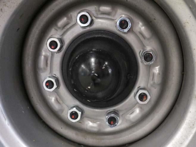
23 Do not open or work (welding, drilling) on the pressure accumulator. Even after being emptied, the accumulator is still preloaded by gas pressure. Always depressurize the pressure accumulator before starting work on the hydraulic system. The pressure gauge should not indicate any pressure. The pressure gauge reading should drop to 0 psi. Only then may service be carried out on the hydraulic system. Changing Implements Secure the machine against unintended rolling! Secure lifted frame parts, under which you will be working, with suitable supports! Caution! Danger of injury caused by protruding parts (tines, discs)! Do not use the packer or other rotating parts when climbing onto the machine. These could start to rotate and you could fall and be seriously injured. In Operation Check the area around the machine (for children!) before setting off and starting operation of the machine. Ensure sufficient visibility! Stay clear of the operating range of hydraulically operated parts. Passengers are not allowed to ride on the machine during operation! Service and Maintenance Ensure that regular tests and inspections are always carried out to schedule, as specified in the operating instructions. Prior to performing maintenance and servicing work, ensure that the machine is positioned on firm, level ground and that it is properly secured against rolling away. De-pressurize the hydraulic system and lower or support the implement. After cleaning, check all hydraulic lines for leaks and loose connections. Check hoses for chafing and signs of other damage. Remedy any faults immediately! Prior to working on the electrical system, disconnect it from the electric power supply. Retighten screwed connections which had been loosened during servicing and maintenance work. Tire Information Do not wash new machines with a steam-jet or high-pressure cleaner. The paint takes approximately 3 months to cure and could thus be damaged if this time has not yet expired. Proper Tire inflation is important. Inflate tires accordingly: o RT-230/ PSI Rear / Gauge wheel 65 PSI. o RT-300/330/ PSI Rear / Gauge wheel 65 PSI. Verify tightness of all wheel lugs. Follow posted torque specs below: o RT-230/ ft-lbs. Rear / Gauge wheel 220 ft-lbs. o RT-300/330/ ft-lbs. Rear / Gauge wheel 220 ft-lbs. 23 P age
24 Transport/Installation There is higher danger of accident during initial installation. Please pay attention to the notes in the corresponding chapters. Delivery The machine with implements is normally delivered completely assembled on a low loader. If parts or modules had to be disassembled for transportation purposes, these will be assembled by our distributor. Depending on the design of the low loader the machine can be unloaded with a tractor, or needs to lift off with suitable lifting gear (forklift truck or crane). Sufficient load bearing capacity of lifting gear and lifting tackle must therefore be assured. Lifting and latching points are identified by labels. When using other lifting points pay careful attention to the center of gravity and the weight distribution. These points must, in any case, only be on the frame of the machine. Installation Instruction of the operator and initial installation of the machine will be carried out by our service engineers or distributors. Any use of the machine without dealer/distributor training is prohibited! The machine can only be released for operation after the instructional session has been conducted by our service engineer / distributor and after the operating instructions have been reviewed and read. There is higher danger of accident during installation and maintenance. Before performing any installation and maintenance work or service, make yourself familiar with the machine and read the operating instructions. Depending on scope of equipment: Take loosely delivered parts off the machine. Check all important screw connections! Lubricate all grease fittings! Check air pressure in tires! Check all hydraulic connections and hoses for correct fastening and function. Immediately rectify any occurring damage or have it corrected by an authorized dealer! 24 P age

25 Transport Depending on country specific regulations and working width, the equipment can be transported on public roads, either attached to a tractor or on a trailer or low loader. The permissible dimensions and weights for transport must be complied with. The tractor must be big enough, so that sufficient steering and braking abilities are assured. If the machine is hitched up in two-point mode, the tractor link arms must be blocked against swinging sideways. For road transport insert the provided yellow safety stops and wing locks pins inserted where necessary). NOTE: Do NOT rest the machine on the safety stops. The machine has a load hold valve in the circuit to hold the cylinder when it is disconnected from the tractor. The yellow safety stops are primarily a safety device in case of a failure in the hydraulic circuit and used during service of the machine. The machine is transported on the rear tires of the transport axle. Never transport the machine on the rear Roll-Flex packer system. On a trailer or low loader, the machine must be secured with tensioning straps, chain binders, or other means. Attach lifting tackle only at the specially marked hoisting/lifting points. DO NOT EXCEED A MAXIMUM TRANSPORTATION SPEED OF 20 MPH (32 KPH) DURING TRANSPORTATION. LOSS OF VEHICLE/MACHINE CONTROL CAN RESULT IN SERIOUS PERSONAL INJURY OR DEATH! Front Hitch decal 25 P age
26 Technical Data Joker RT-230 Working width: Transport height: Transport width: Weight:... 11,500 lbs. Tires: Number of discs: Hydraulic control units:... 3 Hitching:... Drawbar CAT IV /CAT V (Optional) Finishing System:. RollFlex Packer Power requirements:... from HP Hydraulic requirements: Sgt d PSI Joker RT-270 Working width: Transport height: Transport width: Weight:... 12,500 lbs. Tires: Number of discs: Hydraulic control units:... 3 Hitching:... Drawbar CAT IV /CAT V (Optional) Finishing System:. RollFlex Packer Power requirements:... from HP Hydraulic requirements: Sgt d PSI Joker RT-300 Working width: Transport height: Transport width: Weight:... 16,200 lbs. Tires:... 21L24 Number of discs: Hydraulic control units:... 3 Hitching:... Drawbar CAT IV /CAT V (Optional) Finishing System:. RollFlex Packer Power requirements:... from HP Hydraulic requirements: Sgt d PSI Joker RT-330 Working width: Transport height: Transport width: Weight:... 17,200 lbs. Tires:... 21L24 Number of discs: Hydraulic control units:... 3 Hitching:... Drawbar CAT IV /CAT V (Optional) Finishing System:. RollFlex Packer Power requirements:... from HP Hydraulic requirements: Sgt d PSI Joker RT-370 Working width: Transport height: Transport width: Weight:... 18,500 lbs. Tires:... 21L24 Number of discs: Hydraulic control units:... 3 Hitching:... Drawbar CAT IV /CAT V (Optional) Finishing System:. RollFlex Packer Power requirements:... from HP Hydraulic requirements: Sgt d PSI 26 P age
27 Road Lighting Equipment Pin Description 1. Ground 2. Brake 3. Left Turn 4. Not Used* 5. Right Turn 6. Tail Lights 7. 12V +* * If you re not getting Depth Control option to power ON, you may have to switch 12V+ to Pin 4. Check the road lighting equipment at regular intervals to prevent any other road users from being endangered by negligence! 27 P age


28 Setting/Operation Cultivation discs: The serrated discs of the machine cut the harvest residues and the soil and mix the residues in to the soil down to working depth. Maintenance: The bearings are oil filled and therefore, maintenance free. However a bit of penetrating lubricant may be applied to the backside of the bearing hub to lubricate the hub seal. The picture below will identify where to spray any type of sufficient penetrating oil for lubricating the seal. Check the discs regularly for clearance, leaks, tightness and unrestricted rotation. Apply penetrating oil to backside of hub to lubricate the seal. Notes on cleaning: The mechanical seals of the disc hubs are very sensitive. If water has entered them and the machine is then parked over a longer period of time, damage may occur. This can cause corrosion, and both mechanical seal rings may stick together. The mechanical seal rings will then rotate around the O-ring and damage it. Oil would run out of the hub and the bearing would be damaged after a short while with no lubrication. Bearings must therefore not be cleaned with high pressure cleaning equipment. Before longer periods of rest, the bearing locations should be sprayed with a rust dissolver/inhibitor, or similar lubricant. Before resuming operation, the discs should be turned by hand and checked for unrestricted rotation. The disc hub is oil filled as mentioned above. If the seals or O-rings are damaged and further service is required, replace the seals and O-rings and fill the hub with 1.3 ounces 75w140 synthetic gear oil. 28 P age

29 RollFlex Packer The Roll-Flex system can be attached as a rear packer on the machine. While in field use, the packer is used to lift/lower the machine. While in use in the field the machine always travels on the packer. NOTE: Never exceed a maximum operating speed of 8mph while traveling with the Roll-Flex system during Field mode. The packer is not rated for extreme loads at high speeds. Due to the weight of the machine a high consolidation and a fine crumbly, level surface is achieved. RollFlex packer With cohesive soils the packers may pick up more soil and thus become considerably heavier. This can overload components or soil the roads during transportation. Packers must therefore, always be cleaned before road transportation if they have picked up soil. 29 P age


30 Hitching/Unhitching the Machine Nobody is to remain between the tractor and the machine when hitching up and unhitching. Hitching-up: Hitch up the machine to the trailer coupling ring on the tractor. Connect hydraulic lines. Connect the road lighting equipment plug and check the function. Remove the support. Fold the side sections in. Hydraulic Colored Markings: (Hydraulic lines are identified by symbols on the brackets additionally marked with colored caps to avoid mixing up by mistake.) Lift - Green Rear Lift - Blue Fold - Yellow Float Line - Red Hydraulic Hose End caps CAT V Perfect Hitch CAT V Perfect Hitch NOTICE Of Extended Life Decal 30 P age
31 Folding/Unfolding Folding movements must only be performed on firm and level ground. The folding process should only be performed in the field, because the coulter discs could get caught in the ground. On the road, discs and road surface layer could get damaged. Joker RT-Series Folding: Raise machine completely with packer and hitch Lower rear axle to raise machine with rear axle Switch lever on valve block to transport Use lift hydraulics to completely lift packer Fold in the side wings Insert wing lock pins Unfolding: Switch valve block from road to field position Raise machine and wings so it is no longer resting on the wing locks Remove the wing lock pins Unfold and put hydraulic remote into float position Raise rear axle so implement is resting on the packer Do not transport the machine in a position higher than necessary. With the Joker, consider the transport height, especially in case of bridges or low hanging power lines. 31 P age


32 Parking the Machine Only park the machine on a firm and level surface. The Joker can be parked folded in transport position. Pull the spring loaded pin of the jack out to lower the jack base plate and extender. Lower it so it is just about to the ground and aligns with a hole, and release the spring pin to lock it in to position. Using the crank, raise jack to lift hitch off tractor draw bar. Disconnect hydraulic lines, road lighting equipment, and depth control wire. Unhitch the machine. Put a block under the front jack as there is excessive amount of weight from front hitch. Be sure to install any yellow transport stops into position on the front and rear cylinders. Crank Extender and Base Plate Spring Pin Front Hitch and Lift Jack Rear Cylinder & Transport Stop Holder Front Cylinder & Transport Stop Front Bolt-On Transport Bracket Assembly Front Cylinder & Transport Stop (Electronic Machine Only) Rear Lift Cylinder & Transport Stop w/ Front Bolt-On Transport Bracket 32 P age
 Setting: 1.")
33 Depth Setting Electronic Depth Control The depth of the machine is set by the packer and drawbar. The position of the cylinders is controlled by the depth control module in the cab of the tractor. NOTE: Setting should be done on firm level ground. * Red circuit MUST be in float before operating. (This can be either a case drain or a float circuit.) Setting: 1. Raise outside Gauge Wheels of the machine off the ground to their highest set points. (Gauge wheels need to be lifted so they do not interfere with correctly setting the depth control.) For further information see Gauge Wheels in the next section. 2. Turn data panel ON. 3. Lower machine 1-2 inches from the ground. 4. Press and hold the calibrate button until all read-outs read Set the remote valve to run the wings to 40% flow. 6. Set the wing pressure by pushing the wings down with the hydraulic remote to the desired pressure, psi. DO NOT EXCEED 500 PSI! 7. Select the desired depth setting. 8. Raise machine to rephrase cylinders. 9. Set the tractor lift circuit to 100% flow and set timer to 8 seconds. 10. Set the machine down using the remote timer and make sure that the actual depth reads the same as the set depth, if not, adjust timer accordingly. NOTE: If adjusting set point with the machine in the ground, raise the machine past set point and click hydraulic to lower back to set point. 33 P age
34 Tracking Electronic Depth Control Machine may not track straight after initial calibration. To change tracking of the implement adjust the hitch offset knob. To Adjust: 1. If machine is tracking to the right turn hitch offset knob clockwise. 2. Raise machine out of the ground completely and click hydraulic to lower back to set point. 3. If machine is still tracking to the right repeat Steps 1 & If machine is tracking to the left turn the hitch offset know counterclockwise. 5. Raise machine out of the ground completely and click hydraulic to lower back to set point. 6. Adjust hitch offset until the machine is tracking straight. 7. If further adjustment is needed past what the offset allows, repeat the steps again for recalibration. Recalibrating is only needed when changing tractors. Calibration will be saved once the machine is calibrated to the tractor. Offset will only need to be adjusted when tracking is off. 34 P age

35 Depth Setting Manual Depth Control The depth of the machine is set by the packer and drawbar. The positions of the cylinders are controlled by the manual depth control linkage on the machine. Setting: 1. Raise outside Gauge Wheels of the machine off the ground to their highest set points. (Gauge wheels need to be lifted so they do not interfere with correctly setting the depth control.) For further information see Gauge Wheels in the next section 2. For shallower working depth of the machine, turn the handle clockwise. 3. For deeper working depth of the machine, turn the handle counterclockwise. NOTE: The machine will also need to be leveled for proper operation. The machine can be leveled by either adding, or removing stops to the front hydraulic cylinder. Leveling: 1. For shallower working depth of the machine, add stops. 2. For deeper working depth of the machine, remove stops. 35 P age

36 Tracking Manual Depth Control Machine may not track straight after initial setting. To change tracking of the implement add or remove stops from the front cylinder. To Adjust: 1. If machine is tracking to the right, add more stops to the front cylinder. 2. If machine is still tracking to the right, repeat Step If machine is tracking to the left, remove stops from the front cylinder. 4. Add or remove strops from the front cylinder until the machine tracks straight. Setting Wing Pressure The wing pressure is adjustable to keep the wings of the implement level with the rest of the machine when it is in operation. 1. Set the wing pressure by pushing the wings down with the hydraulic remote to the desired pressure between psi. DO NOT EXCEED 500 PSI! Adjust pressure until the machine is level. The pressure gauge will indicate the level of pressure (psi). Gauge showing wing pressure. 36 P age


. 3.")
37 Gauge Wheels The gauge wheels keep the machine steady and maintain the working depth in the ground. The wheels only have a sensing and supporting function. They are not designed as load bearing transport wheels. The gauge wheel can be set, but not until after the depth setting has been completed. When starting work the gauge wheel should be in its highest position. Lower the machine in to the soil at the working depth and then turn the turnbuckle of the gauge wheel to lower the tire to the ground. The gauge wheel is lifted at the headland when the machine is taken out of the ground. Setting Gauge Wheels: 1. Before setting the depth of the implement, raise the gauge wheel to its highest position by turning the turnbuckle. 2. Set the desired machine depth. (See procedure in previous section). 3. Lower the implement to the predetermined set depth in to the ground. 4. Turn the turnbuckle to lower the gauge wheel to the ground. NOTE: The tires should only support the machine on the ground in case of obstructions and following the contour of the field. The frame must always rest on the stop screws. The wheels should not lift up the side wings when in operation. 37 P age
38 Maintenance and Servicing Observe the safety instructions for maintenance and servicing. Your machine has been designed and constructed for maximum power, efficiency and user-friendliness according to a multitude of operating conditions. Your machine has been checked at the factory and by your appointed authorized dealer prior to delivery in order to determine that the machine is in perfect condition. The recommended maintenance and servicing schedule should be carried out at regular intervals in order to maintain failure-free operation. Cleaning The recommended cleaning and maintenance schedule should be carried out at regular intervals in order to maintain operational availability and guarantee optimum performance. The hydraulic cylinders and bearings should not be cleaned with a highpressure cleaner or direct water jet. The seals and bearings are not waterproof under high pressure. Maintenance Periods The maintenance intervals are determined by various different factors. Various operating, weather and soil conditions, as well as working speeds, affect the maintenance intervals, but also the quality of the lubricants and cleaning agents used, determines the time interval required until the next period for scheduled maintenance. The specified maintenance intervals can therefore only be regarded as an indication. The intervals of maintenance work affected have to be adjusted to suit the conditions, should there be any deviations from normal operating conditions. Regular maintenance forms the basis for a serviceable machine. Serviced machines lower the risk of malfunctions and guarantee the efficient application and operation of machines. Before working on or crawling under machine, insert transport stops and follow and follow all noted safety guidelines. See Maintenance Schedule on the following page. Storage Should the machine not be used for a longer period of time, follow these steps: If possible, store the machine under a roofed area. Protect the machine against rust. Only spray with biologically degradable oils, i.e. rapeseed oil. 38 P age
39 Lubricating Machine The machine should be lubricated regularly and after every pressure wash. This ensures operational reliability and reduces the costs of repair work and down time. See Maintenance Schedule below. Hygiene When used according to regulations, lubricants and mineral oil products present no danger to health. You should, however, avoid longer contact to the skin and not breathe in any fumes. Exposure to Lubricants CAUTION: Avoid direct contact with oils by wearing gloves or protective creams. Thoroughly wash off traces of oil on the skin with warm water and soap. Do not clean your skin with petrol, diesel fuel or other solvents. Oil is poisonous. You should immediately visit your doctor if you have swallowed oil. Ensure that lubricants are kept out of reach of children. Never store lubricants in open or unlabeled containers. Avoid skin contact with oily clothes. Change dirty clothing. Never keep oily cloths in your pockets. Dispose of oily shoes as hazardous waste. Rinse oil that has splashed into your eyes with clean water and visit your doctor, if necessary. Absorb spilled oil with suitable bonding agents and dispose of properly. Never extinguish oil fires with water. Only use permissible and suitable extinguishing agents and wear breathing apparatus. Oily waste and waste oil have to be disposed of according to the legal regulations. Check with your local Hazardous Waste Material Management facility. Service HORSCH hopes you are completely satisfied with your machine and the HORSCH company itself. Please contact your distribution partner or authorized dealer in the event of a problem. The customer service employees of our distribution partners and customer service employees of the company HORSCH are available for your support. Please help us solve any technical faults as soon as possible. Provide the customer service staff with the following details in order to prevent unnecessary queries. Customer No. Name of customer service advisor Name and address Machine model and serial number Purchase date and operating hours Type of problem 39 P age
40 Maintenance Schedule Maintenance Schedule After the first few operating hours: Work instructions: Interval: All screwed and plug-in connections Check for tightness and tighten screw connections In operation Lubricate Lubricate the safety pins 40 hours Lubricate the wing cylinder bolts 40 hours Lubricate the bolt on drawbar Daily Lubricate the packer shaft 40 hours Lubricate the lift bearings on the packer shafts Daily Lubricate Manual Depth Control rod 2x season Wheel/Hub Bearings Lubricate the wheel hub bearings (2 pumps) 200 hours Packer Check condition and tight fit Daily Cultivations discs Check for condition tight fit and wear Check oil bath bearings for leaks and tightness Daily Frame and connecting parts Check condition and tight fit Daily Hydraulic system and components Leak, tightness, fastening and chafing Prior to use Brake lines and hoses Check for damage, squashing and kinks Prior to use Air Reservoir Drain off water (during use) Daily Brake System Function test Prior to use Road lighting Condition, function and cleanliness Prior to use At the end of the season Complete machine Carry out servicing and cleaning work Spray the piston rods of the hydraulic cylinders with anti-corrosion agent. 40 P age

 Lubrication")
 : Gauge")

 41 P age")
41 Lubrication Points Lubrication Points: Wing Fold Pivot Pins (x4) Lubrication Points: Front Hitch Pivot Pins (x2) Lubrication Point: Manual Depth Control Rod (x1) Lubrication Points: Gauge Wheel Turnbuckle (x2) Lubrication Points: Transport Wheel Axle Hubs (x2) Lubrication Points: Gauge Wheel Axle Hubs (x2) 41 P age
42 Troubleshooting Problem Cause Solution Machine does not track straight. Machine does not stop at desired depth. Machine acts erratically, does not maintain consistent depth. Machine stops then continues past desired set depth. Entire machine plugs when running. Machine is not level front to back. Cylinders not reaching set points before hydraulic flow stops. SCV lever is being operated multiple times per lift/lower cycle. SCV is still active after all cylinder movement has stopped. Ground speed too slow; working depth too deep. Adjust hitch tilt cylinder. Adjust SCV timer setting so valve returns to neutral within 5 seconds of all cylinder movement stopping. Only activate timer function once per cycle. Refer to tractor operator s manual. Reduce timer setting (if used). Return SCV to neutral within 5 seconds of all cylinders stopping. Increase ground speed up to 10 mph. Reduce tillage depth. Wings plug when running. Wings not running level. Reduce wing pressure so wings are level. Machine lifts slow. Tractor SCV not set to 100%; excessive soil buildup on machine. Set SCV to 100%. Remove soil from machine frame. Tilt cylinder will not move when discs are out of ground. Depth controller prevents tilt cylinder movement when Actual Depth is 0. Turn depth controller off. Adjust tilt cylinder. 42 P age
43 Bolt Tightening Torques - Metric Bolts Bolt tightening Torques - Metric bolts (Ft. Lbs) Bolt Diameter Grade 4.8 Grade 5.8 Grade 8.8 Grade 10.9 Grade 12.9 Wheel Nuts/ Bolts Size Pitch Dry Lubed Dry Lubed Dry Lubed Dry Lubed Dry Lubed Dry * 8* 13* 10* 20* 15* 30* 22* 35* 26* * 14* 24* 18* 28* 20* 52* 38* 62* 48* * 28* 39* 35* 58* 54* 86* 78* 102* 92* * 43* 60* 54* 94* 86* * 65* 120* 102* * 80* * 88* NOTE: Items with (*) indicate torque in Inch/Pounds. All others in Foot/Pounds. 43 P age
 Bolt Diameter SAE Grade 2 SAE Grade 5 SAE Grade 8 L9 Size Thread Dry Lubed Dry Lubed Dry Lubed Lubed 1/4 20 66* 49* 8 75* 12 9 11 1/4 28 76* 56* 10 86* 14 10 13 5/16 18 11 8 17 13 20 18 21 5/16")


44 Bolt Tightening Torques - Imperial Bolts Bolt tightening Torques - Imperial bolts (Ft. Lbs) Bolt Diameter SAE Grade 2 SAE Grade 5 SAE Grade 8 L9 Size Thread Dry Lubed Dry Lubed Dry Lubed Lubed 1/ * 49* 8 75* / * 56* 10 86* / / / / / / / / / / / / / / / / / / / / / / / / NOTE: Items with (*) indicate torque in Inch/Pounds. All others in Foot/Pounds. 44 P age
45 Notes: Go to Top 45 P age

46 HORSCH, LLC * 200 Knutson St. Mapleton, ND USA * * info.us@horsch.com * PN Ver / P age
MT-Series Joker Owner s Manual
 2013 MT-Series Joker Owner s Manual 13/15/20 HORSCH, LLC 200 Knutson St. Mapleton, ND 58059 Telephone: (701) 532-1000 Serial Numbers: MT13 SN Earlier 330013013004 MT15 SN Earlier 330015013024 MT20 SN Earlier
RT-Series Joker. Owner s Manual 230/270/300/330/370
 Issued December 2013 RT-Series Joker 230/270/300/330/370 Owner s Manual Ver. 1.12 02/2016 Serial Numbers: RT-230 SN 310023014001 Current RT-270 SN 310027014001 Current RT-300 SN 310030014001 Current RT-330
OPERATORS MANUAL. JOKER Compact Disc. 6 RT and 8 RT. Horsch, LLC 2013
 OPERATORS MANUAL JOKER Compact Disc 6 RT and 8 RT Horsch, LLC 2013 * The German RT Joker has been discontinued for sales in North America. Contact your local authorized Horsch distributor. Page 1 Contents
HD-Series Joker. Owner s Manual HD 20 / 30 / 40.
 Issued May 2015 HD-Series Joker HD 20 / 30 / 40 Owner s Manual Serial Numbers: HD20 SN 340020015001 Current HD30 SN 340030015001 Current HD40 SN 340040016001 Current 200 Knutson St. Mapleton, ND 58059,
Directions for use VIBRO FLEX 7400
 Directions for use VIBRO FLEX 7400 Contents Introduction... 3 Identification... 3 Explanation of symbols... 4 Safety... 5 General safety advice... 5 Coupling and uncoupling... 5 Three-point hitch or linkage...
LOG CHOP. Hydraulic Wood Guillotine. Owners Illustrated Instruction Book & Parts List
 LOG CHOP Hydraulic Wood Guillotine Owners Illustrated Instruction Book & Parts List Grovebury Road, Leighton Buzzard, Bedfordshire. LU7 4UX. UK. Tel:01525 375157. Fax:01525 385222. Email: enquires@brownsagricultural.co.uk
LOG SPLITTER. Heavy Duty PTO Driven. Owners Illustrated Instruction Book & Parts List
 LOG SPLITTER Heavy Duty PTO Driven Owners Illustrated Instruction Book & Parts List Grovebury Road, Leighton Buzzard, Bedfordshire. LU7 4UX. UK. Tel:01525 375157. Fax:01525 385222. Email: enquires@brownsagricultural.co.uk
ADJUSTING THE GANG ANGLE
 ADJUSTING THE GANG ANGLE 1. Raise the machine until the discs are clear of the ground. 2. Set the diverter valve ( Fig. 1) to the angle position 3. Remove the appropriate angling pin (Fig 2 ) and replace
Smart-Till. Models ST101, ST151, ST203, and ST303. HCC, inc st Avenue Mendota, IL
 Owners Manual Smart-Till Models ST101, ST151, ST203, and ST303 HCC, inc. 1501 1st Avenue Mendota, IL 61342 815-539-9371 www.hccincorporated.com C-1159 May 2010 Safety Most work related accidents are caused
4745 Drill OWNER'S MANUAL (06-08) #
 #") 4745 Drill OWNER'S MANUAL (06-08) # 605865 Identification Your CrustBuster drill is identified by a Serial Number and Model Number. Record these numbers in the spaces provided in this manual and refer
4745 Drill OWNER'S MANUAL (06-08) # 605865 Identification Your CrustBuster drill is identified by a Serial Number and Model Number. Record these numbers in the spaces provided in this manual and refer
ALAMO INDUSTRIAL WARRANTY REGISTRATION INFORMATION
 TEAR TEAR TEAR TEAR TEAR TEAR TEAR TEAR TEAR TEAR TEAR TEAR TEAR TEAR TEAR TEAR TEAR TEAR TEAR TEAR TEAR TEAR TEAR TEAR TEAR 1. PRINT FIRMLY. 2. REMOVE WHITE COPY FOR CUSTOMER RECORDS. 3. REMOVE YELLOW
W & A 12 ROW TOP LEVELING STACKER LEVEL BANDER
 W & A 12 ROW TOP LEVELING STACKER LEVEL BANDER NO. 3640 OPERATOR S MANUAL TO THE OWNER: Congratulations on your purchase of a new W & A Top Leveling Stacker Level Bander. Your selection is an indication
03-SERIES 4 & 6-ROW RIGID & FOLDING PEANUT VINE CONDITIONER OPERATOR S MANUAL THIS MANUAL TO ACCOMPANY MACHINE
 03-SERIES 4 & 6-ROW RIGID & FOLDING PEANUT VINE CONDITIONER OPERATOR S MANUAL THIS MANUAL TO ACCOMPANY MACHINE PART NO. 03-OM-03 Printing Date: SEPT 2012 WARRANTY POLICY KELLEY MANUFACTURING COMPANY (KMC)
ALAMO INDUSTRIAL WARRANTY REGISTRATION INFORMATION
 TEAR TEAR TEAR TEAR TEAR TEAR TEAR TEAR TEAR TEAR TEAR TEAR TEAR TEAR TEAR TEAR TEAR TEAR TEAR TEAR TEAR TEAR TEAR TEAR TEAR 1. PRINT FIRMLY. 2. REMOVE WHITE COPY FOR CUSTOMER RECORDS. 3. REMOVE YELLOW
Operating and Assembly Manual
 Model 1080 Operating and Assembly Manual Midwest Equipment Manufacturing, Inc. 5225 Serum Plant Road Thorntown, IN 46071 08-02-16 SAFETY RULES Remember, any power equipment can cause injury if operated
Operator s Manual. Go Galvanized! YOU'RE ALWAYS AHEAD...WITH A MODERN BEHIND.
 SUMMER 2008 C2 tilting grader blade Operator s Manual YOU'RE ALWAYS AHEAD...WITH A MODERN BEHIND. 003-5336 003-5342 003-5531 003-5544 P.O. Box 790 Beaumont, Tx 77704 409.833.2665 1.800.231.8198 Fax: 409.726.8333
DRILL 2300 SAFETY SECTION
 DRILL 2300 SAFETY SECTION RECOGNIZE SAFETY ALERT SYMBOL WARNING: KEEP RIDERS OFF UNIT Riding on any agricultural equipment is very dangerous. People can be killed or seriously injured when accidentally
ALUMINUM CARGO CARRIER WITH FOLDING RAMP
 ALUMINUM CARGO CARRIER WITH FOLDING RAMP OWNER S MANUAL WARNING: Read carefully and understand all ASSEMBLY AND OPERATION INSTRUCTIONS before operating. Failure to follow the safety rules and other basic
HORSCH Tiger AS LT MT XL
 07/2008 Specialists in modern cultivation and seeding technology HORSCH Tiger AS LT MT XL Art.: 80580202 en Operating Instructions Read carefully prior to starting up! Keep operating instructions in a
Walker Loader Bucket OPERATOR S AND PARTS MANUAL
 Walker Loader Bucket OPERATOR S AND PARTS MANUAL Please Read and Save These Instructions For Safety, Read all Safety and Operation Instructions Prior To Operating Machine P/N 6690 TABLE OF CONTENTS Introduction
tRIPr Chief Grain Cart. Operator s Manual. Operator s Manual
 125-000-01 125-000-01 1tRIPr 1tRIPr Operator s Manual 1210 Chief Grain Cart Operator s Manual Operator s Manual TO THE DEALER Predelivery/Delivery Checklist 1210 Grain Cart PREDELIVERY/DELIVERY CHECKLIST
48 in. DELUXE ALUMINUM CARGO CARRIER WITH RAMP
 48 in. DELUXE ALUMINUM CARGO CARRIER WITH RAMP OWNER S MANUAL WARNING: Read carefully and understand all ASSEMBLY AND OPERATION INSTRUCTIONS before operating. Failure to follow the safety rules and other
Model 858-RH. Operating and Assembly Manual. Palmor Products Inc Serum Plant Road Thorntown, IN 46071
 Model 5-RH Operating and Assembly Manual Palmor Products Inc. 55 Serum Plant Road Thorntown, IN 6071 3/31/015 SAFETY RULES Remember, any power equipment can cause injury if operated improperly or if the
OPERATOR'S MANUAL & PARTS LIST
 GRAVITY GRAIN BOES OPERATOR'S MANUAL & PARTS LIST GRAVITY GRAIN BOES Model 50 (After Serial #14860 & D-Series) Model 85 (After Serial #C104749 & D-Series) Model 90 (After Serial #D0580100 & Up) Model 450
Gopher Eliminator GE-1000 User Manual For all Gopher Eliminator Machines
 Gopher Eliminator GE-1000 User Manual For all Gopher Eliminator Machines 1 Gopher Eliminator GE-1000 Operator s Manual This manual is applicable to all models of the Gopher Eliminator Series. For inquiries
610 BUSHEL MANURE SPREADER
 610 BUSHEL MANURE SPREADER RODA MANUFACTURING 1008 LOCUST ST. HULL, IA. 51239 Art s-way Manufacturing 712-439-2366 Co., Inc. Hwy 9 West - PO Box 288 WWW.RODAMFG.COM Armstrong, IA. 50514 U.S.A 2 INTRODUCTION
EverythingAttachments.com
 EverythingAttachments.com 60 Xtreme Duty Brush Cutter Owner s Manual SAFETY GENERAL SAFETY INSTRUCTIONS AND PRACTICES A careful operator is the best operator. Safety is of primary importance to the manufacturer
W & A 12 ROW TOP LEVELING STACKER LEVEL BANDER
 W & A 12 ROW TOP LEVELING STACKER LEVEL BANDER NO. 3640 OPERATOR S MANUAL TO THE OWNER: Congratulations on your purchase of a new W & A Top Leveling Stacker Level Bander. Your selection is an indication
3-Pt. Quick Hitch. Owner s Manual
 3-Pt. Quick Hitch Owner s Manual WARNING: Read carefully and understand all ASSEMBLY AND OPERATION INSTRUCTIONS before operating. Failure to follow the safety rules and other basic safety precautions may
X-Tractor Series. Cutters INSTRUCTION MANUAL
 INSTRUCTION MANUAL X-Tractor Series Cutters PRINTED IN USA 0305 PART NO. 159R141 Rev. 02 2005 Hale Products, Inc. Hale Products, Inc. reserves the right to make changes at any time, without notice or obligation,
Trench Filler for Compact Utility Loaders
 Form No. 3353-608 Rev A Trench Filler for Compact Utility Loaders Model No. 22472 260000001 and Up Operator s Manual Register your product at www.toro.com Original Instructions (EN) Contents Page Introduction................................
ROTARY BRUSH CUTTERS THE LEADER OF THE PACK OWNER/OPERATOR SAFETY & INSTRUCTION MANUAL
 72 M-AX ROTARY BRUSH CUTTERS THE LEADER OF THE PACK OWNER/OPERATOR SAFETY & INSTRUCTION MANUAL CONTENTS Page 1. Introduction..................................2 2. Safety Instructions...........................3-4
TABLE OF CONTENTS. Warranty Disclaimers Delivery Checklist After Sale Checklist Safety Set Up... 8
 TABLE OF CONTENTS Pickett Equipment Warranty... 2 Warranty Disclaimers... 3 Delivery Checklist... 4 After Sale Checklist... 4 Safety... 5-7 Set Up... 8 Machine Adjustments and Operation... 9 Maintenance
ICEBREAKER. The T12 model. USER MANUAL. Sah-Ko Oy Lumijoentie 6, P.O. Box 13 FI Oulu, FINLAND
 ICEBREAKER The T12 model USER MANUAL Note! P13 T14 in the picture. Sah-Ko Oy Lumijoentie 6, P.O. Box 13 FI-90401 Oulu, FINLAND +358 207 448 500 www.raikomachines.com CONTENTS 1 SAFETY INSTRUCTIONS... 4
AG PRODUCTS, LTD. YOU RE ALWAYS AHEAD... WITH A MODERN BEHIND.
 SUMMER 2016 BADGER DISC HARROW Operator s Manual 011-1156 011-1166 001-1501 001-1501-1 011-1167 001-1501-2 001-1501-3 011-1176 001-1501-4 011-1177 MODERN AG PRODUCTS, LTD. YOU RE ALWAYS AHEAD... WITH A
3800 SERIES SINGLE HYDRAULIC LOCKING TOOLBAR
 3800 SERIES SINGLE HYDRAULIC LOCKING TOOLBAR 2565-774_REV_D 02/2018 OPERATOR S MANUAL PART IDENTIFICATION YETTER MANUFACTURING CO. FOUNDED 1930 Colchester, IL 62326-0358 Toll free: 800/447-5777 309/776-3222
Coulter Applicator. Operator s & Parts Manual R0 Printed In The USA Specifications & Design Subject To Change Without Notice!
 Coulter Applicator Operator s & Parts Manual 4-15-18 17-011R0 Printed In The USA Specifications & Design Subject To Change Without Notice! Warranty Information This equipment was carefully designed and
36 Tiller Wheel Horse Lawn and Garden Tractor Attachment
 Form No. 9 6 Rev B 6 Tiller Wheel Horse Lawn and Garden Tractor Attachment Model No. 797 890000 and Up Operator s Manual English(En) Contents Page Introduction................................ Safety.....................................
OPERATOR S MANUAL REPAIR PARTS CATALOG. Models: SCP-51 & SCP-71 SCP-52 & SCP-72 SCP-91 & SCP-111 SCP-92 & SCP-112 BRILLION FARM EQUIPMENT
 OPERATOR S MANUAL REPAIR PARTS CATALOG Subsoil Chisel Plow Models: SCP-51 & SCP-71 SCP-52 & SCP-72 SCP-91 & SCP-111 SCP-92 & SCP-112 IMPORTANT! Repairs cannot be purchased retail direct from factory. Order
Pro. User Manual. Safe-T-Pull Inc Page 1 of 19
 Pro User Manual Safe-T-Pull Inc. 2015 Page 1 of 19 TABLE OF CONTINENTS 1. Before You Begin...3 Disclaimer...3 What Is Included...3 Unpacking Instructions....4 Claims...4 Contact Us...4 Safety Information...4
SERIES 04 DIAMOND HARROW PRODUCT MANUAL FOR SECTIONS & SETS
 SERIES 04 DIAMOND HARROW PRODUCT MANUAL FOR SECTIONS & SETS TABLE OF CONTENTS Welcome Note 4 Safety 5 Usage Information 7 Normal Packaging 9 Assembly Instructions 10 Operating Instructions 13 Series 04
MODELS 1324 & 1624 & 1824
 THE MODELS 1324 & 1624 & 1824 HYDRAULIC TRENCHERS CONGRATULATIONS! You are now the proud owner of a BARRETO trencher. Please take a moment of your time to look over the following information. Familiarize
ROTARY TILLER. Operation, Service & Parts Manual For "AS" Series. FORM: ASTillerBook.QXD
 ROTARY TILLER Operation, Service & Parts Manual For "AS" Series FORM: ASTillerBook.QXD April 2002 TABLE OF CONTENTS Preparation......................................1 Assembly Instructions.............................2
MK AUGERS POWER SWING KIT ASSEMBLY & OPERATION MANUAL
 MK AUGERS POWER SWING KIT ASSEMBLY & OPERATION MANUAL Read this manual before using product. Failure to follow instructions and safety precautions can result in serious injury, death, or property damage.
STRIP FRESHENER
 2984-150 STRIP FRESHENER OPERATOR MANUAL PARTS IDENTIFICATION 2565-963 02/2018 YETTER MANUFACTURING CO. FOUNDED 1930 Colchester, IL 62326-0358 Toll free: 800/447-5777 309/776-3222 (Fax) Website: www.yetterco.com
POST HOLE DIGGER. Operation, Service & Parts Manual For Models D20 & D40. FORM: D20_40DigRev.QXD
 POST HOLE DIGGER Operation, Service & Parts Manual For Models D20 & D40 FORM: D20_40DigRev.QXD September 2006 Revised August 2009 TABLE OF CONTENTS Introduction.............................1 Preparation..............................2
BEFORE YOU START!! Read the safety messages on the implement as shown in your manual. Observe the rules of safety and common sense!
 To the Owner/Operator/Dealer All implements with moving parts are potentially hazardous. There is no substitute for a cautious, safe-minded operator who recognizes the potential hazards and follows reasonable
Tube-Line Techno-Bale 980
 Tube-Line Techno-Bale 980 Operator's Manual 28287 (05/05/11) 2 One- Year Manufacturer's Warranty For Normal Use With The Exception Of Tires If the equipment does not function properly, or if a manufacturing
Heavy Duty Engine Cranes
 Heavy Duty Engine Cranes Operating Instructions & Parts Manual Model Number ATD-7484 ATD-7485 (Foldable Legs) Capacity 2 Ton 2 Ton Model ATD-7484 Model ATD-7485 WARNING: This product may contain chemicals,
R T SERIES ROTARY TILLER
 R T SERIES ROTARY TILLER Operating and Maintenance Manual TABLE OF CONTENTS 1. PRODUCT WARRANTY. 3 2. CHECKLIST Dealer s File Copy. 4 Customer s File Copy.. 5 3. INTRODUCTION 6 4. SPECIFICATIONS.. 7 5.
Operator s Manual. Manufacturing, Inc. Air Drill Implement SN Z1370- NTA3010 and NTA M
 Operator s Manual NTA3010 and NTA3510 Air Drill Implement SN Z1370- Manufacturing, Inc. www.greatplainsmfg.com! Read the operator s manual entirely. When you see this symbol, the subsequent instructions
<THESE INSTRUCTIONS MUST BE GIVEN TO THE END USER> B&W
 B&W Trailer Hitches 6 Hawaii Rd / PO Box 86 Humboldt, KS 66748 P:60.473664 F:60.869.903 Turnoverball Gooseneck Hitch Installation Instructions MODEL 08
Series 1 Toolbar. Operating Instructions
 P13937 19/12/05 2 Declaration of Conformity DECLARATION OF CONFORMITY Simba International Limited hereby declare that the Product described in this Operators Manual, and defined by the 5 digit Registration
Assembly & Operator s Manual
 Assembly & Operator s Manual LiftGator XTR 1200lbs Removable Liftgate TM Visit our website at: www.liftgator.com WARNING: Read the entirety of this manual before using the LiftGator. Failure to do so can
OPERATOR S MANUAL REPAIR PARTS CATALOG. with ONE & TWO SHANKS BRILLION FARM EQUIPMENT
 OPERATOR S MANUAL REPAIR PARTS CATALOG Subsoil Chisel Plow with ONE & TWO SHANKS MODELS: SCP-1 SCP-2 IMPORTANT! Repairs cannot be purchased retail direct from factory. Order through your Brillion dealer.
Powered Industrial Truck Safety Program
 Powered Industrial Truck Safety Program 0 TABLE OF CONTENTS Forklift Safety Program 1.0 Overview.. 2 2.0 Purpose....2 3.0 Procedures..2 4.0 Responsibilities. 4 5.0 Training Requirements......5 Appendix
3 Ton Trolley Jack. Please read and fully understand the instructions in this manual before operation. Keep this manual safe for future reference.
 Please dispose of packaging for the product in a responsible manner. It is suitable for recycling. Help to protect the environment, take the packaging to the local amenity tip and place into the appropriate
SUNDOWN Operation. & Parts Manual. for Box Blade Models BB15-48, 60 BB20-48, 60, 72 BB30-60, 72, 84, & 96
 SUNDOWN Operation & Parts Manual for Box Blade Models BB15-48, 60 BB20-48, 60, 72 BB30-60, 72, 84, & 96 Operations and Parts Manual Table of Contents Section Page Table of Contents 2 Retail Customer Responsibility
2. PREPARATION 1. SAFETY 3. FRAME 4. TRANSMISSION 5. DRIVE 6. ROW UNIT 7. OPTIONAL EQUIPMENT Monosem Inc.
 TABLE OF CONTENTS 1. SAFETY 2. PREPARATION 3. FRAME 4. TRANSMISSION 5. DRIVE 6. ROW UNIT 7. OPTIONAL EQUIPMENT For the initial preparation of the planter, lubricate the planter and row units. Make sure
GRADING SCRAPERS INDUSTRIAL SERIES OPERATION, SERVICE & PARTS MANUAL FOR MODELS: GSI7-SS, GSI7, GSI8, GSI10, & GSI12.
 GRADING SCRAPERS INDUSTRIAL SERIES OPERATION, SERVICE & PARTS MANUAL FOR MODELS: GSI7-SS, GSI7, GSI8, GSI10, & GSI12 September 2006 FORM: IndGradingScrpr.QXD TABLE OF CONTENTS Safety Information......................1-2
Installation and Operating Manual for Tank and Equipment Cleaning Nozzles Series 5TM
 Installation and Operating Manual for Tank and Equipment Cleaning Nozzles Series 5TM 150 150 150 This instruction manual contains proprietary information which is protected by copyright laws. No part of
2. PREPARATION 1. SAFETY 3. FRAME 4. TRANSMISSION 5. DRIVE 6. ROW UNIT 7. OPTIONAL EQUIPMENT
 TABLE OF CONTENTS 1. SAFETY 2. PREPARATION 3. FRAME 4. TRANSMISSION 5. DRIVE 6. ROW UNIT 7. OPTIONAL EQUIPMENT For the initial preparation of the planter, lubricate the planter and row units. Make sure
Operator s/parts Manual
 Operator s/parts Manual 3-Point Solid Stand Drills Pull Hitch Package Manufacturing, Inc. P.O. Box 5060 Salina, Kansas 67402-5060! Read the operator s manual entirely. When you see this symbol, the subsequent
Wheel Horse. 44 Snowthrower. for 5xi Lawn and Garden Tractors. Model No & Up. Operator s Manual
 FORM NO. 8 Rev A Wheel Horse Snowthrower for 5xi Lawn and Garden Tractors Model No. 7966 890050 & Up Operator s Manual IMPORTANT: Read this manual, and your tractor manual, carefully. They contain information
From Serial Number to P /11/06
 From Serial Number 12699 to 12723 P15002 07/11/06 2 Declaration of Conformity DECLARATION OF CONFORMITY Simba International Limited hereby declare that the Product described in this Operators Manual, and
ROTARY TILLER. Operation, Service & Parts Manual For P-P/C Series. November 1996 (Rev. 4-05) FORM: PTillerBook.QXD
 FORM: PTillerBook.QXD") ROTARY TILLER Operation, Service & Parts Manual For P-P/C Series FORM: PTillerBook.QXD November 1996 (Rev. 4-05) TABLE OF CONTENTS Preparation......................................1 Assembly Instructions.............................2
ROTARY TILLER Operation, Service & Parts Manual For P-P/C Series FORM: PTillerBook.QXD November 1996 (Rev. 4-05) TABLE OF CONTENTS Preparation......................................1 Assembly Instructions.............................2
EZ Hauler 2500 Training & Procedure Manual
 EZ Hauler 2500 Training & Procedure Manual Load Capacity One of the most important considerations when operating this machine is the Load Capacity of the EZ Hauler 2500 s boom. The maximum weight capacity
DECLARATION OF CONFORMITY
 Operator Manual Simba TL300 / TL350 Great Plains Manufacturing, Inc. www.greatplainsmfg.com Read the operators manual entirely. When you see this symbol, the subsequent instructions and warnings are serious
60in. Acreage Rake. Owner s Manual
 60in. Acreage Rake Owner s Manual WARNING: Read carefully and understand all ASSEMBLY AND OPERATION INSTRUCTIONS before operating. Failure to follow the safety rules and other basic safety precautions
Tube-Line Techno-Bale 960. Operator's Manual
 Tube-Line Techno-Bale 960 Operator's Manual One- Year Manufacturer's Warranty For Normal Use With The Exception Of Tires If the Equipment does not function properly, or if a piece is defective due to a
Operator s Manual. Manufacturing, Inc. Three-Section Folding Drill SN S S /9/ M-A
 Operator s Manual SN S1399+ 3S-3000 Three-Section Folding Drill Manufacturing, Inc. www.greatplainsmfg.com! Read the operator s manual entirely. When you see this symbol, the subsequent instructions and
Telescoping. Rams INSTRUCTION MANUAL
 INSTRUCTION MANUAL Telescoping Rams PRINTED IN USA 0110 PART NO. 159R128 Rev. 05 2010 Hale Products, Inc. Hale Products, Inc. reserves the right to make changes at any time, without notice or obligation,
ATV TRACK KIT. Operator s Manual Installation Instructions Service Instructions Replacement Parts List. Effective Date: October, 2012
 p/n 2258-642 ATV TRACK KIT Operator s Manual Installation Instructions Service Instructions Replacement Parts List Track Assembly Kits (p/n 1436-204) Mounting Assembly Kits (p/n 1436-205) 1436-815) Effective
INSTRUCTIONS AND SPARE PARTS READ CAREFULLY BEFORE OPERATING MACHINE
 SP Series OPERATING INSTRUCTIONS AND SPARE PARTS READ CAREFULLY BEFORE OPERATING MACHINE July 2006 Technical Data SERIES "SP Model SP 150 SP 250 SP 300 SP 400 SP 500 Capacity 149 li 198 li 250 li 302 li
1000-lb Hydraulic Truck Crane
 1000-lb Hydraulic Truck Crane Owner s Manual WARNING: Read carefully and understand all ASSEMBLY AND OPERATION INSTRUCTIONS before operating. Failure to follow the safety rules and other basic safety precautions
UTS 696 Under Tailgate Spreader Owner s Manual
 July 15, 2004 Lit. No. 94838 UTS 696 Under Tailgate Spreader Owner s Manual Read this manual before installing or operating the spreader. This manual is for UTS 696 Under Tailgate Spreaders with serial
OPERATION MANUAL DBW Bale Wagon DFW Feeder Wagon
 OPERATION MANUAL DBW Bale Wagon DFW Feeder Wagon To the Owner/Operator/Dealer All implements with moving parts are potentially hazardous. There is no substitute for a cautious, safe-minded operator who
3-Pt. Subsoiler. Owner s Manual
 3-Pt. Subsoiler Owner s Manual WARNING: Read carefully and understand all ASSEMBLY AND OPERATION INSTRUCTIONS before operating. Failure to follow the safety rules and other basic safety precautions may
Original. User Manual & Install Guide. Safe-T-Pull Inc. Page 1 of 15
 Original User Manual & Install Guide Safe-T-Pull Inc. Page 1 of 15 TABLE OF CONTINENTS 1. Before You Begin...3 Disclaimer...3 What Is Included...3 Claims...3 Contact Us...4 Safety Notes...4 2. Introduction...5
Printed: Doc-Nr: PUB / / 000 / 00
 ORIGINAL OPERATING INSTRUCTIONS Hilti HTE-P 33 dispenser It is essential that the operating instructions are read before the tool is operated for the first time. Always keep these operating instructions
PORTABLE Q-CATCH 86 SERIES CHUTE, ALLEY & TUB PRODUCT MANUAL arrowquip.com
 PORTABLE Q-CATCH 86 SERIES CHUTE, ALLEY & TUB PRODUCT MANUAL 1-877-275-6075 cs@arrowquip.com arrowquip.com CONTENTS Safety Precautions 1 Risk Assessment 2 Q-Catch 86 Series Head Gate Assembly 3 Operating
OXDALE PRODUCTS LTD POST HOLE BORER KEEP FOR FUTURE REFERENCE
 OXDALE PRODUCTS LTD POST HOLE BORER KEEP FOR FUTURE REFERENCE 1 Safety 1 Safety Signs 6 Mounting Instructions 7 Operating Instructions 11 Borer Operation 13 Special Operating Conditions 14 Removing the
2 TONNE TROLLEY JACK
 2 TONNE TROLLEY JACK 61829 IMPORTANT: Please read these instructions carefully to ensure the safe and effective use of this product and save these instructions for future reference. This manual has been
SERVICE GUIDE AGRICULTURAL TRACK REMOVAL INSTALLATION INSPECTION ALIGNMENT CPB-305
 SERVICE GUIDE CPB-305 AGRICULTURAL TRACK AGCO Challenger MT735, 745, 755, 765 AGCO Challenger MT835, 845, 855, 865, 875 REMOVAL INSTALLATION INSPECTION ALIGNMENT TABLE OF CONTENTS Table of Contents Introduction...
Operator s Manual & Repair Parts Manual. Do Not Use or Operate This Equipment Until You Have Read and Understand This Manual
 Operator s Manual & Repair Parts Manual Do Not Use or Operate This Equipment Until You Have Read and Understand This Manual The purpose of this manual is to explain maintenance requirements and adjustments
TITAN UNIVERSAL UNIT MOUNTED FLOATING RESIDUE MANAGER
 2967-030 TITAN UNIVERSAL UNIT MOUNTED FLOATING RESIDUE MANAGER YETTER MANUFACTURING CO. FOUNDED 1930 Colchester, IL 62326-0358 Toll free: 800/447-5777 309/776-3222 (Fax) Website: www.yetterco.com E-mail:
TRAILER SPRAYER MODEL: 500 BW OPERATOR'S MANUAL DO NOT OPERATE THIS EQUIPMENT UNTIL THIS MANUAL HAS BEEN READ AND UNDERSTOOD.
 TRAILER SPRAYER MODEL: 500 BW OPERATOR'S MANUAL DO NOT OPERATE THIS EQUIPMENT UNTIL THIS MANUAL HAS BEEN READ AND UNDERSTOOD. Part Number: 07.09145D November 2007 MILLER-ST.NAZIANZ,INC. P.O. BOX 127 ST.
Model 1000 Low Profile Tailgate Spreader Receiver Mount
 November 1, 2018 Lit. No. 94380, Rev. 06 Model 1000 Low Profile Tailgate Spreader Receiver Mount Installation Instructions Read this manual before installing or operating the spreader. The receiver mount
NILFISK BA 500 Service Manual
 NILFISK BA 500 Service Manual Model 66324400 12/94 Form Number 043023 TABLE OF CONTENTS Batteries...21 Brush Drive Belt Adjustment Or Replacement...7 Brush Drive Motor - Carbon brush Inspection... 8 Brush
Operator s Manual. Manufacturing, Inc. Inline Ripper Hitch
 Operator s Manual Inline Ripper Hitch Manufacturing, Inc. www.greatplainsmfg.com! Read the operator s manual entirely. When you see this symbol, the subsequent instructions and warnings are serious - follow
Original Operating Manual
 matev GmbH Nürnberger Str. 50 90579 Langenzenn T +49 (0) 9101 9087-0 F +49 (0) 9101 9087-20 info@matev.eu www.matev.eu Original Operating Manual Snow blade SRM-FB 120 CD Angle adjustment mechanical Version
Engine Crane Owner s Manual
 Engine Crane Owner s Manual Model Number ATD04 Capacity Ton WARNING: This product may contain chemicals, including lead, known to the State of California to cause cancer, birth defects or other reproductive
Predelivery Instructions
 PINK Predelivery Instructions SR5030 Split-Row Planter Manufacturing, Inc. P.O. Box 5060 Salina, Kansas 67402-5060! Read this manual entirely. When you see this symbol, the subsequent instructions and
Sawhorse with Chainsaw Holder
 Sawhorse with Chainsaw Holder Owner s Manual Chainsaw not included. WARNING: Read carefully and understand all ASSEMBLY AND OPERATION INSTRUCTIONS before operating. Failure to follow the safety rules and
4400-Lb. Capacity Pallet Jack
 Read carefully and understand all ASSEMBLY AND OPERATION INSTRUCTIONS before operating. Failure to follow the safety rules and other basic safety precautions may result in serious personal injury. Item#
3 TONNE TROLLEY JACK
 3 TONNE TROLLEY JACK 16407 These instructions accompanying the product are the original instructions. This document is part of the product, keep it for the life of the product passing it on to any subsequent
1500 Series Roll Off Hoist. Owner s Manual (5-06)
") 1500 Series Roll Off Hoist Owner s Manual (5-06) Section 1: General Information Introduction Safety Information Warranty Information Table of Contents Section 2: Operation Operating the P.T.O. Operating
1500 Series Roll Off Hoist Owner s Manual (5-06) Section 1: General Information Introduction Safety Information Warranty Information Table of Contents Section 2: Operation Operating the P.T.O. Operating
OPERATOR S MANUAL HWH COMPUTER-CONTROLLED 2000 SERIES LEVELING SYSTEM AND SPACEMAKER ROOM EXTENSION SYSTEMS
 HWH CORPORATION R OPERATOR S MANUAL HWH COMPUTER-CONTROLLED R 2000 SERIES LEVELING SYSTEM AND SPACEMAKER ROOM EXTENSION SYSTEMS R FEATURING: Touch Panel Leveling Control Air Leveling (With or Without Tag
Operator s Manual. Go Galvanized! YOU'RE ALWAYS AHEAD...WITH A MODERN BEHIND.
 fall 2010 3pt & quick attach Bale spears & 3pt bale carrier Operator s Manual YOU'RE ALWAYS AHEAD...WITH A MODERN BEHIND. 318-1006-i 318-1005-i 020-1500 020-1502 P.O. Box 790 Beaumont, Tx 77704 409.833.2665
Multi-Ject Aerator Model no.: BA-400 Operation & Parts Manual
 Multi-Ject Aerator Model no.: BA-400 Operation & Parts Manual P a g e 2 Table of Contents Cover Page 1 Table of Contents 2 Welcome to Bannerman 3 Warranty 4 Work Safety 5 Three Point Hitch Attachment Procedure