Envoy Communications Gateway , Rev 03
|
|
|
- Rebecca Ryan
- 5 years ago
- Views:
Transcription

1 INSTALLATION AND OPERATION MANUAL Envoy Communications Gateway , Rev 03
4 74 98 29 56 Fax : +33 (0)4 74 98 38 15 http://www.enphase.com/fr sas@enphaseenergy.")
2 Corporate Headquarters Contact Information Enphase Energy Inc N. McDowell Blvd. Petaluma, CA USA Phone: Contact Enphase Energy SAS Hub Business 2 BP Lyon Aéroport Saint Exupéry France Tel : +33 (0) Fax : +33 (0) sas@enphaseenergy.com Informazioni di contatto Enphase Energy Srl Via Volta, Desio (MB) - Italia informazioni@enphaseenergy.com support.italy@enphaseenergy.com Contact Enphase Energy UK LTD Fairbourne Drive, Atterbury Milton Keynes, MK10 9RG United Kingdom Phone: +44 (0) info@enphaseenergy.com Other Information For third-party license information, refer to Product information is subject to change without notice. All trademarks are recognised as the property of their respective owners. Copyright 2012 Enphase Energy. All rights reserved. 2
3 Table of Contents Important Information... 4 Read this First... 4 Safety Instructions... 4 The Enphase Envoy Communications Gateway... 5 Other Elements in the Enphase System... 6 How the Envoy Communications Gateway Works... 6 Envoy Installation... 7 Planning and Preparation... 7 Preinstallation Checks... 7 Installation Flow... 8 Install the Envoy Add Serial Number Label to Map Register the Envoy Find a Location for the Envoy Connect Ethernet and Power Cables Connect Power Line Communication Bridges (Optional) Select Language Check the Envoy s Progress Wall Mount the Envoy (Optional) Configure the Grid Profile Build the Virtual Array View System Performance in Enlighten Envoy Operation First Scan for Microinverters LCD Screen Display at Initial Start Up Initial Communications Check Subsequent Start Up Normal Operation Using the Envoy LCD Menu Initiating a Scan for New Microinverters Performing a Communications Check Viewing the Grid Configuration Enabling a Connection to Enphase Disabling a Connection to Enphase Selecting a New Locale (Change Language Display) How the Envoy Works with Enlighten Networking and Firewall Info Using Enlighten to Check Envoy Status Troubleshooting Power Line Communication Troubleshooting Issue: The Microinverter Count is Lower than the Number of Installed Units Issue: Envoy Displays Fewer than Three Bars Issue: Envoy Displays Zero Bars Local Area Networking Troubleshooting Issue: IP Address Problems Issue: LCD Screen Displays -Web Issue: LCD Screen Displays Envoy Failure +Web or -Web Issue: The Envoy has Good Signal Strength but is Too Far from the Router Replacing an Envoy Envoy Local Interface Connecting to the Envoy through the Site s LAN Directly Connecting to the Envoy without a Broadband Router Home Screen Production Screen Inventory Screen Administration Screen Administration Screen Tasks Change or View the Grid Profile Set Up Device Scan Control Set the Time Zone (optional) Other Admin Tasks Event Messages Technical Data

4 Important Information Read this First Follow the instructions in this manual. These instructions are key to the installation and maintenance of the Enphase Envoy Communications Gateway (Envoy ). To ensure the safe installation and operation of the Envoy, note the following safety symbols that appear throughout this document to indicate dangerous conditions and important safety instructions. WARNING! This indicates a situation where failure to follow instructions may be a safety hazard or cause equipment malfunction. Use extreme caution and follow instructions carefully. NOTE: This indicates information that is very important for optimal system operation. Follow instructions closely. Safety Instructions Perform all electrical installations in accordance with all local electrical standards. Do not attempt to repair the Envoy; it contains no user-serviceable parts. Tampering with or opening the Envoy will void the warranty. If the Envoy fails, please contact Enphase Customer Support for assistance. Before installing or using the Envoy, please read all instructions and cautionary markings in the technical description and on the Envoy. 4

5 The Enphase Envoy Communications Gateway The Envoy is an integral component of the Enphase Energy Microinverter system. It operates between the Enphase Microinverters and the Enphase Enlighten web-based monitoring and analysis software. The Envoy functions as a gateway and monitors the microinverters that are connected to the PV modules. The Envoy collects energy and performance data from the microinverters over on-site AC power lines. It then forwards that data to Enlighten, via the Internet, for statistical reporting. The three key elements of an Enphase system are the: Enphase Microinverter Enphase Envoy Communications Gateway Enphase Enlighten web-based monitoring and analysis software This integrated system maximises energy harvest, increases system reliability, and simplifies design, installation and management. The following diagram shows the Envoy in the system. 5
 algorithm.")
6 Other Elements in the Enphase System The Enphase Microinverter is a fully integrated device that converts the DC output of the PV module into grid-compliant AC power. In addition to performing the DC to AC conversion, it maximises the PV modules' energy production by using a sophisticated Maximum Power Point Tracking (MPPT) algorithm. This integrated system maximises energy harvest, increases system reliability, and simplifies design, installation and management. The Enphase Enlighten web-based monitoring and analysis software analyzes the per-module data collected by each communicating microinverter. Enlighten automatically detects any shortfall in energy production, identifies possible causes, and suggests solutions. Enlighten constantly monitors every Enphase Microinverter connected to the Envoy and is essential for monitoring and troubleshooting. How the Envoy Communications Gateway Works Installation and operation of the Envoy require no specialised equipment or unique computer or networking expertise. To the Local Area Network (LAN), the Envoy is just another host on the network, much like a personal computer. The Envoy simply connects to the on-site router for communications with the Enphase Enlighten monitoring and analysis website. The Envoy communicates with the individual microinverters using the existing power lines in the residence or business. As part of the commissioning process, installers must use the Envoy to configure the microinverters with an appropriate grid profile setting. Otherwise, the microinverters will not begin producing power. After the Envoy is installed and completes its initial scan, it maintains an internal database of all known Enphase Microinverters at the site it manages. At regular intervals, the Envoy polls each microinverter for its energy data. Using the site s broadband router, the Envoy then forwards that information to Enlighten. The Envoy also reports any error conditions that affect it or the microinverters. You can view both energy data and error conditions in Enlighten. The Envoy incorporates power line and Internet communications functions. As shown in the diagram, one side of the Envoy communicates with the microinverters through power lines at the site. The other side of the Envoy communicates with the Internet using a standard Ethernet/network cable plugged into your broadband router. 6
7 Envoy Installation Planning and Preparation Review the following preinstallation checks before you install the Envoy. Preinstallation Checks Before installing the Envoy, make sure that the site meets the following minimum requirements: Standard AC outlet is available Laptop or other computer is available for set up If you plan to use the Enlighten web-based monitoring and analysis software, additional requirements are: Always-on broadband Internet connection Broadband router with spare Ethernet port Up-to-date web browser to view Enlighten. Supported browsers are Internet Explorer 8 or higher, Firefox 3.6 or higher, Chrome 5 or higher, and Safari 4 or higher. Enlighten requires Adobe Flash Player 10 or higher. Check the Envoy shipping box for the following items: Envoy Communications Gateway Ethernet cable AC power cord Power line communication bridges (included with some models) Envoy Communications Gateway Quick Install Guide If you plan to wall-mount the Envoy, you need two #8 (4.166 mm diameter) screws and a screwdriver. 7
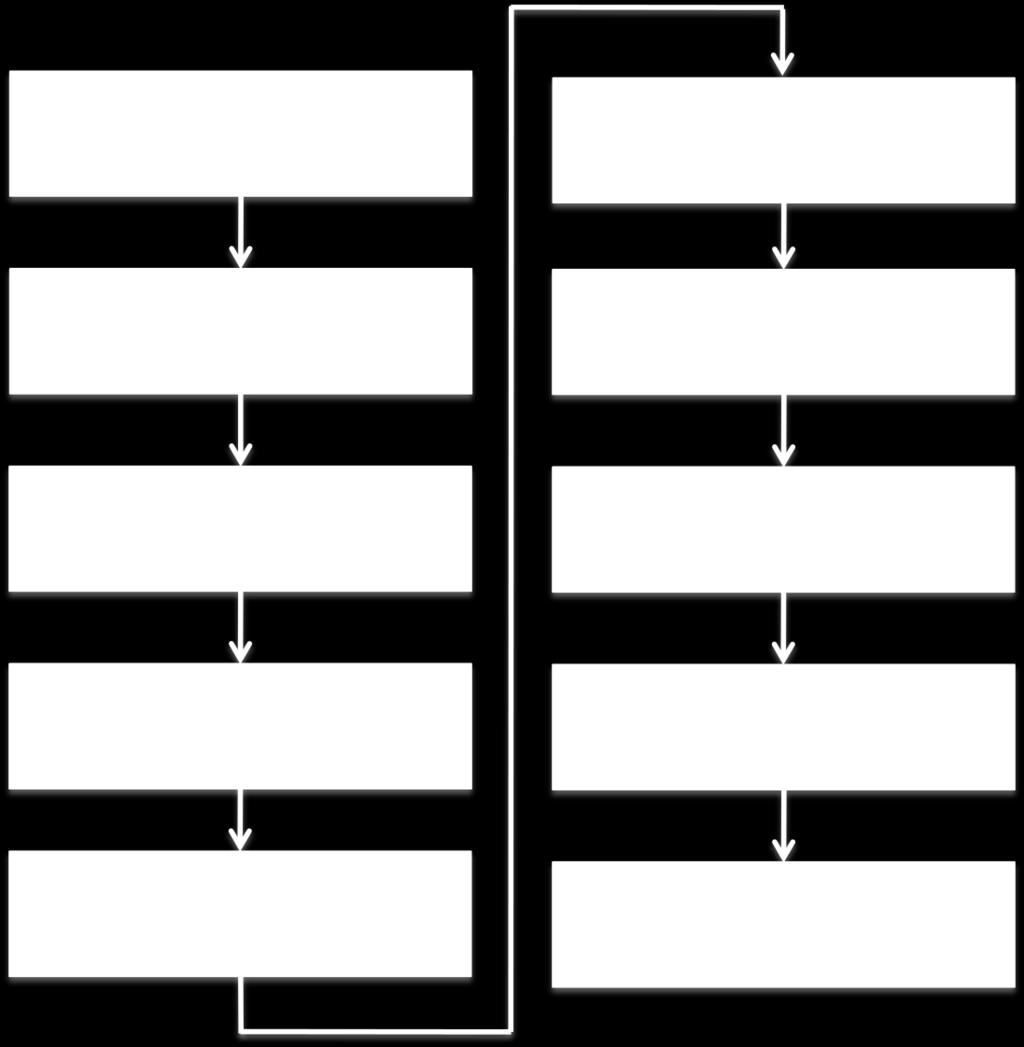
8 Installation Flow 8
9 Install the Envoy To install the Envoy, perform the following steps while referring to the following diagram. BEST PRACTICE: When powered up and connected for the first time, the Envoy may retrieve an automatic upgrade from Enphase. Because this upgrade may take up to 15 minutes, connect the Envoy first at the site (connect to both AC power and the broadband router) so that it performs the upgrade well before the solar module installation is complete. WARNING! Do not remove power from the Envoy if the LCD displays: Upgrading... Do Not Unplug. 9
10 1. Add Serial Number Label to Map a. Remove the Envoy s removable serial number label as shown in the diagram. b. Attach the serial number label to the microinverter installation map, or make note of it for registration in the next step. 2. Register the Envoy Register the Envoy at the beginning of the PV installation. a. Use your previously issued username and password to log in to in Enlighten. If you haven t registered, go to and click Enlighten Login to register. b. If you haven t already started an activation, click Add a New System at the Installer Dashboard. If you have already registered the site, find the system under Installations in Progress, and register the Envoy serial number in the space provided online. 3. Find a Location for the Envoy Enphase recommends that the Envoy be placed as close to the AC mains as possible. This ensures that the Envoy receives the strongest possible signal from each microinverter. The Envoy must be indoors and can be placed on a table or it can be wall mounted. For wall mounting instructions, see Wall Mounting on page 13. a. Locate an AC outlet close to the AC mains. b. Place the Envoy so that its AC cord can reach this outlet. 4. Connect Ethernet and Power Cables The Envoy must obtain a DHCP (Dynamic Host Configuration Protocol) IP address and have a path to the Internet. The Envoy will request this IP address from the broadband router during the power-up sequence. Two small green LEDs on the Ethernet port indicate Internet link and activity. One LED will be solid green, and the other will blink every few seconds. a. Plug the Ethernet cable into the Ethernet port on the Envoy. b. Plug the other end of the cable into a spare port on the broadband router. NOTE: Next to the Ethernet port on the Envoy, there are two USB ports. You cannot use the USB ports for a wired or a wireless Ethernet connection. c. Plug the AC power cord into the AC input on the Envoy. d. Plug the other end of the power cord into a dedicated AC outlet (not a power strip). For best results, the outlet should be near the AC mains. WARNING! Do not remove power from the Envoy if the LCD displays: Upgrading... Do Not Unplug. WARNING! Do not plug the Envoy into a power strip, surge protector, or uninterruptable power supply (UPS). The surge suppression or filtering from a power strip or other protective device can substantially diminish communication performance. Also, if possible, do not plug a power strip into the same outlet that the Envoy is using. The surge suppression or filtering components of a power strip may still interfere with communications if they are near the Envoy. 10
11 5. Connect Power Line Communication Bridges (Optional) If the Envoy needs to be located away from the router, at a distance where an Ethernet cable is not practical, use power line communication bridges or purchase a wireless Ethernet bridge. Bridges allow the Envoy to communicate with the broadband router without the need for additional Ethernet cabling. To install the bridges: WARNING! Do not remove power from the Envoy if the LCD displays: Upgrading... Do Not Unplug. a. Plug one of the bridges into the same AC outlet that the Envoy is using. b. Connect one end of the Ethernet cable to the Ethernet port on the Envoy. c. Connect the other end of that Ethernet cable to the bridge. d. Plug the other bridge into an AC outlet near the broadband router. e. Connect one end of a second Ethernet cable to the second bridge. f. Connect the other end of the Ethernet cable to the broadband router. g. Reapply power to the Envoy to force it to refresh its IP address. 6. Select Language After the Envoy starts up it will request that you set the Language. The Envoy LCD panel will scroll through the available language settings, and will continue to scroll until you make a selection. When you see the setting you need, press the Menu button and hold it down for two seconds. English Français Deutsch Italiano 11
12 7. Check the Envoy s Progress After installing your Envoy, you can check its progress: a. Check the Internet connection. Look for the +Web indication. If it still shows -Web 15 minutes after connecting to the broadband router, see Local Area Networking Troubleshooting on page 30. NOTE: Power production shows as 0W and 0kWh until the microinverters are discovered and monitoring begins Web 0W 0kWh 25 b. Check the device count (shown as 25 in the illustration). An automatic device scan will begin to detect microinverters. c. Check the power line communications. The number of Level bars on the Envoy LCD Level/Devices screen should be three or more. (The illustration shows three bars.) If there are fewer than three bars, see Power Line Communication Troubleshooting on page 29. d. Soon, the Envoy will display Priority Scan is Active on the LCD screen. Check that the Envoy LCD shows a complete device count after about 30 minutes. If it does not, see Power Line Communication Troubleshooting on page 29. e. When all microinverters at the site have been discovered, use the Envoy Device Scan Control menu to stop the device scan: Press and hold the Envoy menu button (on the right side of the Envoy). Release it when the LCD window displays Disable Device Scan. NOTE: For sites with neighbouring Enphase systems, a device scan should not be allowed to run overnight because it may discover neighbouring microinverters when they first power-up in the morning. Always stop the device scan in the afternoon, before leaving the site. f. Refer to LCD Screen Display on page 20 for more information. Level: [ ] Devices: 25 12
13 8. Wall Mount the Envoy (Optional) NOTE: Before mounting the Envoy, it is best to perform a Communications check, as described on page 23, to find the best location for your Envoy. After you have positioned your Envoy for optimal communications and it is has begun to detect devices, you can mount the Envoy on a wall. To do this: a. Use two drywall screws or wall anchors (not included) to affix the Envoy to the wall, mounted at the dimensions shown. You will need two #8 (4.17 mm or 0.16 in. diameter); maximum screw head diameter is 8.9mm (0.35 in.). b. Slide the Envoy onto the mounting screws, aligning the Envoy screw holes with the screws installed in step a. 13
14 9. Configure the Grid Profile The following steps describe how to configure the grid profile. After all of the microinverters at the site are detected, you can apply the grid profile. Each Grid Profile contains a set of trip points. Trip points are input voltage or frequency values that trigger the microinverters to shut down. These trip points vary from region to region. If you need to change the grid profile subsequent to this initial procedure, follow the steps in Change or View the Grid Profile on page 36 NOTE: Enphase Microinverters will not begin exporting power until the Envoy Communications Gateway is installed and has detected all of the microinverters at the site. In addition, the grid profile must be configured and the Envoy must have propagated these settings to the microinverters. a. Open the Internet browser application on a computer that is connected to the same local network as the Envoy. b. In the browser address window, enter the IP address shown in the LCD screen of the Envoy. Once the browser has successfully connected with the Envoy, the System Overview screen is displayed in the browser window. c. From the Language menu, select your preferred language. d. Click on Inventory and verify that all installed microinverters are detected. e. Click Administration to access the Administration menu. The default log in credentials for the Administration menu are: Username: admin Password: admin Click to select Language Click to access the Administration menu. 14

15 The System Administration screen appears. f. From the Admin menu, select Device Grid Configuration. Click to select Device Grid Configuration The Grid Configuration screen appears. This screen allows a licensed solar professional to select and apply the appropriate Grid Profile for the site. g. Select a Country regulatory specification. h. Select a Grid profile. Click to select a Country regulatory specification Click to select a Grid Profile Click Apply Grid Profile i. Click Apply Grid Profile. The Apply Profile screen appears. This screen allows you to generate a report to confirm that the microinverters have been set with the updated grid profile. 15


16 j. Click View Device Profile Report. The Grid Profile Report screen appears. Click to View Grid Profile Report k. Enter the site information in the window provided. Enter site information here. l. Use your browser to send this report to your printer or to save it to a file. After printing or saving the file, you can send it to the local regulatory agency to confirm the grid profile and trip point settings. 16
17 The report will look like the following example. 17


18 10. Build the Virtual Array When the system is energised and the Envoy detects at least one microinverter, the installer can begin to create the virtual array in Enlighten from the installation map they created. a. Log in to Enlighten. b. Use Array Builder to create the virtual array in Enlighten. c. Use your installation map as your reference. To see the Array Builder demo, go to Once the virtual array is built, Enlighten displays a graphic representation of the PV system. It also shows detailed current and historical performance information. 11. View System Performance in Enlighten Once the array is built and the system is activated, the installer and the system owner can log in to Enlighten to view site data. a. If you have not done so already, log in to Enlighten to view system data. b. Refer to How the Envoy Works with Enlighten on page 27 for more information. 18
19 Envoy Operation First Scan for Microinverters A newly installed Envoy automatically performs an initial scan to discover all of the microinverters that are installed and powered up at the site. This initial scan continues to search for new microinverters for eight hours from initial start up of the Envoy. This one-time scan is not repeated automatically. During the scan, you will notice some values increasing on the Envoy display. NOTE: If the Envoy was not factory built with software release 3.2, the initial scan will run for seven days. The initial scan time was reduced from seven days to eight hours with release 3.2. If the Envoy upgrades to release 3.2, after an initial scan has begun, the initial scan duration will still be seven days. NOTE: If the eight-hour scan expires before installation of microinverters is complete, a new scan must be initiated. The steps for initiating a new device scan are described on page 23 of this manual. WARNING: Stop the scan once all of the devices are detected (see page 12). For sites with neighbouring Enphase systems, a new device scan should not be allowed to run overnight because it may discover neighbouring microinverters when they first power-up in the morning. The Envoy identifies each device by its unique serial number. If a microinverter is added or replaced at the site, you must initiate a new scan so that the Envoy can discover the new microinverter. The steps for initiating a new device scan are described on page 23 of this manual. After the Envoy has detected at least one new device, it will automatically enter Priority Scan mode. The LCD screen will display the following, where nnnn represents the number of microinverters (devices) detected. Priority Scan is Active. Devs: nnnn When the Envoy does not detect a device during a polling interval (usually 5 minutes), it will exit Priority Scan mode. If, subsequently, the Envoy detects another device, it will return to Priority Scan mode. It will remain in this mode until it again completes an interval where no new devices are detected. NOTE: While Priority Scan is active, power production, power line communication level, and grid profile information screens continue to display on the Envoy LCD screen. 19
20 LCD Screen Display at Initial Start Up When the Envoy is started up for the first time, it goes through the initial boot sequence. During this initial boot sequence, the Envoy LCD screen display progresses as shown: [e] Enphase Energy Booting [ ] {LANGUAGE SELECTION} Initial Communications Check The last two screens in the initial sequence alternate until the Communications Check ends, after 20 minutes. The Envoy normally displays "-Web" for two to three minutes after the first start up. It then sends the first report to Enlighten. When Enlighten responds, the Envoy displays +Web. Subsequent Start Up After a power outage or Envoy shut down, the Envoy is ready to work just five minutes after reapplying power. You will know the Envoy has completed booting and has started normal operation when it displays both an IP address and the +Web status indication in the LCD screen. The normal, post installation boot sequence is similar to the initial start up, although the Initializing Data screen is not repeated. Initializing Data 2012/06/06 16:21:20 Starting R /06/06 16:21: Web 2407W 783kWh 25 Communications check Searching Devices Web 2407W 783kWh 25 Level: [ ] Devices: 25 20
21 Normal Operation Once the Envoy completes a scan, it begins or resumes normal operation. At this point, the indicators in the LCD screen show current values for your system. This is the home screen: Web 2407W 783kWh 25 It may be a few minutes before energy data appears or increases on the home screen after starting up the Envoy or initiating a scan. Information shown during normal operation includes: Local IP address, for example: (your actual local IP address will be different). The Envoy will attempt to get a dynamically assigned DHCP (Dynamic Host Configuration Protocol) IP address during power up sequence. The Envoy uses the DHCP IP address as a path to the Internet. If is shown, the Envoy has not yet acquired a dynamic IP. Refer to Troubleshooting on page 29, if this address continues to display. Web connection indication: +Web. The web status indicates whether the Envoy is connected to Enlighten. Indication of the present power-production, in watts: (n)w (where n is a number) Indication of the life time kilowatt hours reported to this Envoy: (n)kwh (where n is a number) Indication of the number of online microinverters producing power and reporting in to the Envoy: (n) (where n is a number). The number of microinverters displayed will be zero at night. After the Envoy establishes an IP address and the web connection, the Envoy periodically contacts an NTP (Network Time Protocol) server so that it can maintain an accurate local time. Using the Envoy LCD Menu Use the Envoy Menu button located on the right side of the Envoy to access the Envoy LCD menu. 1. Press and hold this button. After two seconds the Envoy menu appears in the Envoy s LCD screen. Menu Button 2. Continue holding the Menu button. Menu items will appear in the following order: 21
22 3. To select a menu item, release the Menu button when the desired menu item appears. The menu continues to cycle as long as you are pressing the Menu button. The Exit Menu option returns to the normal (default) display, usually the Home screen. See the following sections for detailed procedures. Exit Menu Enable Device Scan Disable Device Scan Enable Communication Check Disable Communication Check View Grid Configuration Get New IP Address Enable Connection To Enphase Disable Connection To Enphase Select New Locale 22
23 Initiating a Scan for New Microinverters If you add additional microinverters to an existing system or replace a microinverter, you will need to run a scan to detect the new devices. To initiate a scan after you add new microinverters to an existing Enphase system perform the following steps. Alternatively, you can initiate a scan through the administration page when connected to the Envoy local interface with a computer or via Enlighten (refer to Using Enlighten to Check Envoy Status on page 28). 1. Press and hold the Envoy Menu button. After two seconds the Envoy menu appears. 2. Continue holding the Menu button. When the LCD screen displays Enable Device Scan, release the Menu button. Enable Device Scan The LCD screen then reads: Device scan active for 00d:00h:30m The Envoy begins a 30-minute scan (if a longer scan is not already in progress) to identify all of the microinverters deployed at the site. 3. Use your previously issued username and password to check for the new microinverter in Enlighten. If you do not have a link to Enlighten, go to and click Enlighten Login. From here you can register (if not already done) and view data on a per-microinverter basis (and, hence, a per-pv module basis). 4. To disable or cancel a scan, press and hold the Envoy Menu button for two seconds to view the Envoy menu. 5. When the LCD screen displays: Disable Device Scan, release the Menu button. Disable Device Scan Performing a Communications Check If you are unsure of where the Envoy should be located for maximum performance, you can install the Envoy in various locations and check signal strength at each location. Normally, a communications check starts automatically after an Envoy restart. Alternatively, you can initiate a communications check with the Envoy Menu button or through the Administration page when connected to the Envoy local interface with a computer. You can also use Enlighten (see Using Enlighten to Check Envoy Status on page 28). NOTE: Device scans and communications checks can only be done during daylight hours when the microinverters are active (that is, powered by the PV modules). To use the Envoy Menu button to initiate a communications check: 1. Press and hold the Menu button on the right side of the Envoy to bring up the Envoy menu on the LCD screen. 23
24 2. When the LCD screen displays Enable Communication Check, release the Menu button. Enable Communication Check The LCD screen then reads: Comm check enabled for 20min The Envoy begins a 20-minute communications check to assess the signal strength between the Envoy and the microinverters detected at the site. Until the Envoy begins detecting microinverters, the display reads: Communications check Searching Devices When the Envoy begins detecting microinverters, the display shows power line communication Level and Device count: Level: [ ] Devices: 25 To the right of the word Level, you ll see brackets enclosing zero to five bars. The example above shows three bars. NOTE: Until microinverters are detected, the Level indicator shows no bars. Signal strength is acceptable if three to five bars are displayed and all devices are accounted for. One to two bars may not be sufficient for consistent communication. 3. If, after 15 minutes, fewer than three bars are displayed, refer to Power Line Communication Troubleshooting on page 29. The Devices counter displays the number of microinverters detected and will increase until all microinverters are detected. Ultimately, the number of microinverters detected should match the number of installed microinverters. 4. After 20 minutes, the communications check stops. To stop the communications check before it times out, press and hold the menu button to activate the Envoy menu. When Disable Communication Check is displayed, release the menu button. Viewing the Grid Configuration To view the grid configuration (trip points profile) for the site, do the following. NOTE: You cannot change the grid profile using this menu. To change this profile, and for more information on this feature, see Change or View the Grid Profile on page Press and hold the Envoy Menu button. After two seconds the Envoy menu appears. 2. Continue holding the Menu button. When the LCD screen displays View Grid Configuration, release the Menu button. 24
25 View Grid Configuration The LCD screen then reads: Gathering Grid Configuration Data If a grid profile has not been applied, the following screen is displayed: This indicates that the microinverters are not yet configured with a grid profile. No Grid Config. Applied 3. If needed, configure these settings as described in Change or View the Grid Profile on page 36. If a grid profile has been applied, the following screens are displayed. You can press the menu button at any time to exit this process. (n) total devices Number of microinverters detected. (n)unsettable devices Number of microinverters that cannot be set with a grid profile. (n)devices are set with (local spec) (n)are propagating with (local spec) (n)devices have failed Number of microinverters that are set with a grid profile and the name of the specification being used. Number of microinverters that are in the process of being set and the name of the specification being used. Number of devices that failed to be set with a grid profile. Checking grid config Select to exit Updating grid configuration data. 4. Press the menu button to exit this menu. 25
26 Enabling a Connection to Enphase The Enable Connection to Enphase menu item creates a secure connection to Enphase allowing Enphase personnel to troubleshoot the system remotely. To open a connection to Enphase: 1. Press and hold the Envoy Menu button. After two seconds the Envoy menu appears. 2. Continue holding the Menu button. When the LCD screen displays Enable Connection to Enphase, release the Menu button. Enable Connection To Enphase The LCD screen now reads: Enabling Connection Once the connection is open, the LCD will return to the default display. Disabling a Connection to Enphase The Disable Connection to Enphase menu item closes the secure connection to Enphase. To close a connection to Enphase: 1. Press and hold the Envoy Menu button. After two seconds the Envoy menu appears. 2. Continue holding the Menu button. When the LCD screen displays Disable Connection to Enphase, release the Menu button. Disable Connection To Enphase The LCD screen now reads: Disabling Connection Once the connection is closed, the LCD will return to the default display. 26
27 Selecting a New Locale (Change Language Display) You can set the LCD to display in English, French, Italian, or German. To do this: 1. Press and hold the Envoy Menu button. After two seconds you will enter the Envoy menu. 2. Continue holding the Menu button. When the LCD screen displays Select New Locale, release the Menu button. Select New Locale 3. The Envoy LCD panel will scroll through the available locale settings. When you see the setting you need, press the Menu button and hold for two seconds. English Français Deutsch Italiano How the Envoy Works with Enlighten The Envoy operates between the Enphase Microinverters and the Enphase Enlighten web-based monitoring software. The Envoy collects energy and performance data from the microinverters and forwards that data to Enlighten, via the Internet, for reporting. Once you have registered the system and successfully installed the Envoy, Enphase will set up an account for the site owner. You can then use Array Builder, a tool available to installers, to build the virtual array. You will need to use the installation map you created during installation as a reference during this task. NOTE: To see the Array Builder demo, go to If you do not already have an account, please go to for more information. When you complete the registration and installation, Enphase sends account information to the site owner so that they can log in to the Enlighten website and view system performance. Enlighten provides a wide range of information on system and PV module performance. A graphical representation of the PV array provides at a glance information on the status of each PV module. You can also access more detailed information, including current and lifetime performance metrics. You can even access Enlighten on your mobile device and view current performance information wherever you are. 27
 (TCP:443). The Envoy uses NTP (Network Time Protocol) (UDP:123) to periodically synchronise time/date with an external pool of NTP servers.")
28 Networking and Firewall Info The Envoy communicates with Enlighten by initiating outbound TCP (Transmission Control Protocol) connections to Enphase over HTTPS (Hypertext Transfer Protocol over Secure Socket Layer) (TCP:443). The Envoy uses NTP (Network Time Protocol) (UDP:123) to periodically synchronise time/date with an external pool of NTP servers. You do not need to open any inbound firewall ports for normal operation. NOTE: The Envoy automatically reports system performance data to Enphase upon connection to the Internet. Please consult the Enphase privacy policy at to learn more about Enphase's use of this data. Using Enlighten to Check Envoy Status To check status of Enphase equipment, do the following: 1. Log on to Enlighten to view the array. Click Inverters. A list of equipment appears that including the Envoy(s) all of the microinverters that the Envoy has detected. The column on the far right lists the status of each microinverter. 2. To view status information for the Envoy, click the Envoy serial number. Click to Check Signal Click to Rescan 3. From here you can choose to Check Signal Strength or Rescan for Devices as needed. 28
29 Troubleshooting The following sections describe possible problems and solutions. For information on system status and event messages, see Event Messages on page 43. For more extensive information, refer to Troubleshooting an Enphase Installation at Power Line Communication Troubleshooting At power-up, the Envoy performs a Communications check. After a few minutes, it will display a number of bars in the LCD screen. This value, from zero to five, indicates the signal strength of the power line communication between the Envoy and the microinverters. Any time the Envoy is restarted, it automatically performs a communications check. However, there may be times when you need to manually initiate a check. To do this: Press and hold the Envoy menu button. Release it when the LCD window displays Enable Communication Check. The check will run for 20 minutes. Note the number of bars shown in the Communications check. Level: [ ] Devices: 25 Signal strength is acceptable if three to five bars are displayed and all devices are accounted for. One to two bars may not be sufficient for consistent communication. Zero bars means that the Envoy needs to be relocated, or it means that one or more electrical appliances are causing interference. Troubleshoot power line communication issues as described in the following. Issue: The Microinverter Count is Lower than the Number of Installed Units This may indicate that the Envoy is not done scanning/discovering the entire array. Alternatively, it may indicate that the Envoy is having difficulty communicating over the power lines. It could also be a result of low light levels and the PV module voltage being too low for the microinverter to power up. To troubleshoot the issue: Make sure that the Envoy is plugged directly into the wall and not into a power strip or surge protector. Relocate your Envoy as close to the electrical service panel (AC mains) as possible. This ensures that the Envoy receives the strongest possible signal from each microinverter. Try unplugging any other device that may be sharing the outlet with the Envoy. Or, as an alternative, plug the Envoy into a circuit that supports fewer electronic appliances. Appliances sharing a receptacle with the Envoy may interfere with power line communication. If this problem occurs when light levels are low, try again during daylight hours. Issue: Envoy Displays Fewer than Three Bars Follow the procedure (previous) for Issue: The Microinverter Count is Lower than the Number of Installed Units. 29
30 Issue: Envoy Displays Zero Bars The following conditions may exist. Is there a phase imbalance? Ask the electrician to measure the conductors and neutral line to verify that the phases are balanced. If the phases are not balanced, electricians must recheck the wiring. Is the system energised? PV modules power microinverters, PV modules provide power only during daylight hours, and microinverters communicate only when powered. Run another scan during daylight hours. Check that the circuit breaker(s) for the PV array are in the ON position. For the Envoy to communicate with the microinverters, the PV circuit breakers must be in the ON position in the electrical AC mains. Verify that the PV modules are connected to the microinverters. The Envoy is plugged into a circuit on the primary AC mains, but the PV circuit breakers are on a downstream subpanel: The primary AC mains is full and doesn t have additional capacity to add circuit breakers. Add a subpanel with a small subset of circuit breakers. In this case, it is best to add an additional 5-Amp circuit breaker and then run an outlet off that subpanel. Plug the Envoy into that AC outlet, so that it can be close to the PV circuit breaker. Local Area Networking Troubleshooting To the Local Area Network (LAN), the Envoy is just another host on the network, much like a personal computer. Enphase offers technical support at support@enphaseenergy.com for Envoy issues, but Enphase's Support responsibility does not extend to the premises network or LAN. Issue: IP Address Problems If the IP address displayed on the Envoy s LCD screen is , or if the IP address does not match the DHCP subnet on the internal network, this means that the Envoy was unsuccessful in obtaining a DHCP lease from the router. Check network connectivity to the router or other DHCP server. You may also wish to contact your Internet Service Provider or refer to your router documentation for help. Check that you are using a broadband router and not a switch or a hub. Many hubs and switches cannot provide a DHCP lease and may not allow the Envoy to connect to the web. Use the Envoy menu button to Get New IP Address, and then allow 30 to 60 seconds for the new IP address to appear on the Envoy LCD screen. Two small green LEDs on the Ethernet port indicate Internet link and activity. One LED will be solid green, and the other will blink green every few seconds. If the LEDs are not both on or blinking, try using a new Ethernet (CAT5) cable in place of the existing cable. Unplug all units in the chain, applying power again in this order: 1) modem, 2) router, and 3) Envoy. Allow a few minutes for the IP address to be reassigned. Issue: LCD Screen Displays -Web This means that the Envoy has no connection to the Enlighten website. To troubleshoot the issue: Check network connectivity to the router. You may also wish to contact your Internet Service Provider or refer to your router documentation for assistance. Unplug all units in the chain, applying power again in this order: 1) modem, 2) router, and 3) Envoy. Allow a few minutes for the IP address to be reassigned. Allow a few minutes longer. If the Envoy has recently received a valid IP address, it will likely display +Web momentarily. 30
31 Issue: LCD Screen Displays Envoy Failure +Web or -Web This message displays after the Envoy has tried unsuccessfully three times to initialise. Unplug the Envoy from the AC outlet and plug it in once again. Leave it in place for at least 15 minutes. If it continues to display Envoy Failure or if it never moves beyond the Initialization stage, contact Enphase Customer Support Issue: The Envoy has Good Signal Strength but is Too Far from the Router In this case, you may need to use power line communication bridges or a wireless Ethernet bridge. Replacing an Envoy If problems remain after following the troubleshooting steps above, contact Enphase at support@enphaseenergy.com. If Customer Support authorises an Envoy replacement (RMA), follow the steps below. 1. Disconnect the Ethernet cable and power cord from the old Envoy. 2. When the replacement Envoy arrives, connect it to the Ethernet cable and power cord. 3. Verify that the new Envoy powers up. The Envoy LCD may display "Upgrading... Do Not Unplug" for up to 15 minutes. Wait for this to complete before proceeding. 4. Verify that the new Envoy indicates +Web within 15 minutes. If not, follow the network troubleshooting steps above. 5. Verify that the new Envoy start discovering microinverters within 20 minutes of starting up. If necessary, use the LCD menu (or the Enlighten Envoy page) to start a new device scan during daylight hours. (See Using the Envoy LCD Menu on page 21.) 6. After all microinverters have been discovered, stop the new device scan using the LCD menu. (See Using the Envoy LCD Menu on page 21.) 7. Assess the power line communications by running a Communication Check from the LCD menu (or from the Enlighten Envoy page) during daylight hours. (See Using the Envoy LCD Menu on page 21.) If fewer than three bars are shown, relocate the Envoy for better power line communications. 8. Ship the old Envoy to Enphase using the supplied RMA shipping label. 31
32 Envoy Local Interface The Envoy relays data to Enlighten, and connection to the Enphase Enlighten web-based monitoring and analysis software requires an Internet connection. However, if there is no broadband router at the installation site, you can communicate directly with the Envoy using the Ethernet port and a personal computer with a web browser. Connecting to the Envoy through the Site s LAN The following steps describe how to access the Envoy data through the site s LAN (local area network). 1. Open an Internet browser application on a computer connected to the same LAN as the Envoy. 2. In the browser address window, enter the IP address displayed in the LCD screen of the Envoy. Once the browser has successfully connected with the Envoy, the home screen is displayed in the browser window. Directly Connecting to the Envoy without a Broadband Router The following steps describe how to access the Envoy data through the local connection in the absence of a broadband router. 1. Connect one end of the Ethernet cable supplied with the Envoy to the Ethernet port on the Envoy. 2. Connect the other end of the Ethernet cable to the Ethernet port of the computer. 3. Open an Internet browser application on the computer. 4. In the browser address window, enter the IP address displayed in the LCD screen of the Envoy. NOTE: If you fail to make a connection at this point, you can manually configure your subnet to and subnet mask to If this does not correct the problem, contact Enphase Customer Support (mailto:support@enphaseenergy.com). Once the browser has successfully connected with the Envoy, the home screen is displayed in the browser window. 32
33 Home Screen The home screen provides a system overview and shows the current status of the microinverters that have been identified by this Envoy. From this screen, you can access other screens in the interface. 33

34 Production Screen To view system energy harvest statistics for your system, click Production from the Envoy home screen to navigate to the production screen. Inventory Screen To view a listing of the devices in your system, click Inventory from any screen to navigate to the inventory screen. 34
35 Administration Screen The Administration screen of the Envoy local interface contains several configurable options. Click Administration to access this menu. NOTE: For Envoy performance reasons, Enphase does not recommend giving the Envoy a publicly accessible IP address. However, if you must place the Envoy on a public-facing IP address, Enphase recommends that you change the admin password to disallow unauthorised modification to your Envoy. (This situation is rare, since consumer-grade routers normally provide the Envoy with an internal network IP address that is not publicly accessible.) For reference, your private/internal IP address space will be in the x.x, (-31).x.x, 10.x.x.x or x.x range. If you are unsure if your Envoy is on the public Internet, contact your network administrator or Internet Service Provider. The default login credentials for the Administration menu are: Username: admin Password: admin Administration Screen Tasks The following sections describe several Administration Screen tasks. Perform these tasks only when needed. Administration tasks include: Manage the Grid Profile Set Up Device Scan Control Set Time Zone Other Admin Tasks 35
36 Change or View the Grid Profile Many Enphase Microinverters have field adjustable voltage and frequency trip points. Trip points are input voltage or frequency values that trigger the microinverters to shut down when the values are exceeded. If local regulations require adjustments to these trip points, the installer can set up the system to use an alternate Grid Profile (set of trip points). NOTE: Only an authorised installer, following the requirements of the local regulatory authority, is allowed to make Grid Profile adjustments. NOTE: Grid profile changes are applied only after a microinverter is detected. In some regions and in some situations, microinverter trip points must be adjusted to account for high grid voltage or for local conditions. Grid profile management tasks include: Adjust system trip points for frequency and voltage if required by local utilities Reset trip points to default values View or verify current grid profile Generate a report for confirmation of site settings to the utility or other authority To change a grid profile, you need a Change Token. Change tokens are issued on a per Envoy serial number basis. Contact Enphase Customer Support for your Grid Profile Change Token as directed on the screen. 1. From the System Overview screen, click on Inventory and verify that all installed microinverters are detected. 2. Click Administration to access the Administration menu. The default log in credentials for the Administration menu are: Username: admin Password: admin The System Administration screen appears. Click to select Device Grid Configuration 36

37 3. From the Admin menu, select Device Grid Configuration. The Device Grid Configuration screen appears. This screen allows a licensed solar professional to select and apply the appropriate trip points for the solar installation. Click to select a Country regulatory specification Click to select a Grid profile Enter your token here. Click to Apply Grid Profile 4. Select a Country regulatory specification. 5. Select a Grid profile that is applicable for your region. 6. Make note of the Envoy serial number and the authorization number on the screen. You will need this information in the following steps. 7. Click the link to the Enlighten website. (If you do not already have an account, click Enlighten Login at the Enlighten website to register.) Note that this link will not appear if the Envoy shows -Web. NOTE: If the Envoy displays -Web, see Local Area Networking Troubleshooting on page


38 8. Once logged in at the Enlighten website, locate the Grid Profile Change Token widget. If you don t see this widget add it now: Click Add a widget. Select Grid Profile Change Token. 9. Enter the Envoy serial number. Copy this token. 10. Enter the authorization number from the Envoy Interface. 11. Click Get Token. 12. Copy the token. 13. Paste or enter the token in the Grid Profile screen. 14. Click Apply Grid Profile. This propagates the settings to the microinverters. 38

39 The Apply Profile screen appears. This screen allows you to generate a report to confirm that the microinverters have been set with an updated grid profile. 15. Click View Device Profile Report. Click to View Grid Profile Report The Device Profile Report screen appears 16. Enter the site information in the window provided. Site Name 123 Avenue Town, State/Province Country Enter site information here. 17. Use your browser to send this report to your printer or to save it to a file. After printing or saving the file, you can send it to the local regulatory agency to verify the trip point settings. 39
40 The report will look like the following example. 40

41 Set Up Device Scan Control The controlled device scan differs from other Envoy device scans in that it allows control over scan period, scanning method, and number of devices. When first installed, the Envoy initiates an eight-hour scan. This initial scan is the only scan needed for most systems. NOTE: At sites with more than 100 microinverters, we recommend using the controlled device scan presented here and specifying the total number of devices to be discovered. This will speed up the discovery process. To run a controlled device scan to detect new or previously undetected microinverters: 1. From the Admin menu, choose Device Scan Control. The Device Scan Control screen appears. 2. Enter a Scan Duration in days:hours:minutes (e.g., 0:00:60 to indicate zero days, zero hours, and 60 minutes). The scan duration will depend on many factors, such as number of devices to be detected and quality of power line communication. You may want to start with a onehour scan and increase the duration as needed. 3. Although optional, it is best practice to enter a value for Total Devices. Enter a value in this field. The Envoy will stop scanning once it has detected the given number of devices. NOTE: The Total Devices option can be used in conjunction with the Priority Duration option to help discover any last few microinverters. 4. Enter a Priority Duration (optional) in days:hours:minutes (e.g., 0:00:20 to indicate zero days, zero hours, and 20 minutes). If you enter a value in this field, the Envoy will make scanning its sole activity for the period specified. NOTE: The Priority Duration option should only be used in limited situations, e.g., at large sites or sites experiencing problems discovering devices with the normal scan. 5. Click Start Scan to complete this task. The LCD screen will display the following, where nnnn represents the number of microinverters (devices) detected. Priority Scan is Active. Devs: nnnn 41

42 Set the Time Zone (optional) Ordinarily, the Envoy obtains the time zone setting from Enlighten. If you do not have an Internet connection for the Envoy, you may want to set the local time zone. This step is not necessary if the Envoy is reporting to Enlighten. To set the time zone: 1. From the Admin menu, choose Date, Time, Time Zone. 2. Under Time Zone Setting, select a time zone from the Select Time Zone drop down menu. 3. Click Update timezone setting to complete this task. Other Admin Tasks Other Admin menu options not described in this manual are not required for normal system operation and should only be performed when recommended by Enphase. 42
Envoy Communications Gateway
 INSTALLATION AND OPERATION MANUAL Envoy Communications Gateway 141-00014, Rev 04 Corporate Headquarters Contact Information Enphase Energy Inc. 1420 N. McDowell Blvd. Petaluma, CA 94954 USA Phone: +1 707-763-4784
Installation and Operations Manual. Envoy Communications Gateway
 Installation and Operations Manual Envoy Communications Gateway 2 Contact Information Enphase Energy Inc. 201 1 St Street Petaluma, CA 94952 Phone: 707-763-4784 TOLL FREE: 877-797-4743 Fax: 707-763-0784
Envoy Communications Gateway
 INSTALLATION AND OPERATION MANUAL Envoy Communications Gateway 141-00011, Rev 06 Contact Information Enphase Energy Inc. 1420 N. McDowell Blvd. Petaluma, CA 94954 http://www.enphase.com Enphase Energy
Envoy Communications Gateway
 INSTALLATION AND OPERATION MANUAL Envoy Communications Gateway 141-00011, Rev 05 Contact Information Enphase Energy Inc. 1420 N. McDowell Blvd. Petaluma, CA 94954 http://www.enphase.com info@enphaseenergy.com
Installation and Operations Manual. Envoy Communications Gateway
 Installation and Operations Manual Envoy Communications Gateway Contact Information Enphase Energy Inc. 201 1 St Street Petaluma, CA 94952 Phone: 707-763-4784 TOLL FREE: 877-797-4743 Fax: 707-763-0784
Installation and Operation Manual. Envoy Communications Gateway
 Installation and Operation Manual Envoy Communications Gateway Contact Information Enphase Energy Inc. 201 1 St Street, Suite 300 Petaluma, CA 94952 Phone: 707-763-4784 TOLL FREE: 877-797-4743 Fax: 707-763-0784
SNMP dedicated to ORVALDI Solar Infini
 SNMP dedicated to ORVALDI Solar Infini User s Manual Management Software for Solar Inverter Table of Contents 1. 2. 3. Overview...1 1.1 Introduction...1 1.2 Features...1 1.3 Overlook...1 1.4 Installation
ET9500 BEMS Interface Box Configuration Guide
 ET9500 BEMS Interface Box Configuration Guide APPLICABILITY & EFFECTIVITY Explains how to install and configure ET9500 BEMS Interface Box. The instructions are effective for the above as of August, 2015
Quick Setup Guide. WARNING! Connect this product to an AC power source whose voltage is within the range specified on the product's nameplate.
 Thank you for purchasing the Raritan PX intelligent power distribution unit (PDU). The intended use of the Raritan PX is distribution of power to information technology equipment such as computers and
Operation Manual Pika Islanding Inverter X7602/X Part of the Pika Energy Island M
 Operation Manual Pika Islanding Inverter X7602/X11402 Part of the Pika Energy Island M00010-17 Islanding Inverter Serial Number: RCP Number: We are committed to quality and constant improvement. All specifications
Enphase M215 PRODUCTIVE SIMPLE RELIABLE. Enphase Microinverters
 Enphase Microinverters EnphaseM215 The Enphase M215 Microinverter with integrated ground delivers increased energy harvest and reduces design and installation complexity with its all-ac approach. With
CP /240-MC4 User Manual
 CP-250-60-208/240-MC4 User Manual Chilicon Power LLC Dec 2015 1 CONTENTS Important Safety Instructions... 3 Safety Instructions... 3 CP-250 Microinverter System Introduction... 4 Inverter Label Information...
INSTALLATION USER MANUAL
 INSTALLATION & USER MANUAL DYNAMIC LOAD MANAGEMENT -PREMIUM- This document is copyrighted, 2016 by Circontrol, S.A. All rights are reserved. Circontrol, S.A. reserves the right to make improvements to
ELD DRIVER GUIDE June 21, 2018
 ELD DRIVER GUIDE June 21, 2018 Contents Getting Started with PrePass ELD...4 Enroll in the PrePass ELD Program... 4 For a Carrier Enroll in the ELD Service... 4 For a Driver Get Driver Login Information...
Wallbox Commander. User Guide WBCM-UG-002-EN 1/11
 Wallbox Commander User Guide 1/11 Welcome to Wallbox Congratulations on your purchase of the revolutionary electric vehicle charging system designed with cuttingedge technology to satisfy your daily needs.
Getting started with
 PART NO. CMA113 MADE IN CHINA 1. Measuring CAT II 2. Max. voltage 250V ~ 3. Max. current 71 Amp Getting started with Electricity consumption & Solar PV generation monitoring single phase, for homes fitted
CP-250E-60/72-208/240-MC4 Microinverter with Modular Trunk Cable
 CP-250E-60/72-208/240-MC4 Microinverter with Modular Trunk Cable Chilicon Power Aug 2016 1 CONTENTS CP-250E Microinverter System... 3 The CP-100 Cortex Gateway... 3 Important Safety Information... 4 Inverter
Installation and Programming Manual Part: Building Network Interface Card Product: 4100ES
 Installation and Programming Manual Part: Building Network Interface Card 4100-6047 Product: 4100ES Cautions and Warnings READ AND SAVE THESE INSTRUCTIONS- Follow the instructions in this installation
Installing a Programmed Fronius SCERT in a Managed AC Coupled system
 Installing a Programmed Fronius SCERT in INTRODUCTION This document is included with Fronius SCERT PV Inverters that have been programmed. It applies only to units that have been programmed and are ready
One-Stop Service: Monitoring and Managing.
 One-Stop Service: Monitoring and Managing. The highest quality from the market leader Solar-Log devices are the most accurate and reliable data loggers on the market. Offer your customers high-quality
Cloudprinter.com Integration
 Documentation Cloudprinter.com Integration Page 1/ Cloudprinter.com Integration Description Integrating with a Cloudprinter.com has never been easier. Receiving orders, downloading artwork and signalling
Dominion PX. Quick Setup Guide. Before You Begin. Mounting Zero U Models Using L-Bracket. Zero U Size. 1U and 2U Size
 Dominion PX Quick Setup Guide Thank you for purchasing the Dominion PX intelligent power distribution unit (PDU). The intended use of the Raritan Dominion PX is distribution of power to information technology
User Manual Solar Charge Controller 3KW
 User Manual Solar Charge Controller 3KW Version: 1.3 CONTENTS 1 ABOUT THIS MANUAL... 1 1.1 Purpose... 1 1.2 Scope... 1 1.3 SAFETY INSTRUCTIONS... 1 2 INTRODUCTION... 2 2.1 Features... 2 2.2 Product Overview...
Installation Instructions & Users Manual
 Installation Instructions & Users Manual UTILITY/ BUILDING INPUT 120 VAC ( OPTION) 15-20A N L CONTROL BOARD G SECURITY LIGHTING POWER SUPPLY (OPTION) CHARGER- POWER SUPPLY ASSBY XFMR (OPTION) CBM MODEL
User Manual SMA FUEL SAVE CONTROLLER 2.0
 User Manual SMA FUEL SAVE CONTROLLER 2.0 ENGLISH FSC20-BA-en-22 100590-00.03 Version 2.2 Legal Provisions SMA Solar Technology AG Legal Provisions The information contained in these documents is the property
Battery System User Manual for Panasonic LJ-SK56A BATTERY SYSTEM USER MANUAL FOR PANASONIC LJ-SK56A
 Battery System User Manual for Panasonic LJ-SK56A BATTERY SYSTEM USER MANUAL FOR PANASONIC LJ-SK56A TABLE OF CONTENTS 1.0 CONTACT INFORMATION... 3 2.0 IMPORTANT SAFETY INFORMATION... 3 2.1 Warnings...
Contents Getting Started with PrePass ELD...4 Starting a Trip...7 During a Trip Co-Driver Features... 14
 UPDATED February 2, 2018 Contents Getting Started with PrePass ELD...4 Enroll in the PrePass ELD Program... 4 For a Carrier Enroll in the ELD Service... 4 For a Driver Get Driver Login Information... 4
SP PRO KACO Managed AC Coupling
 SP PRO KACO Managed AC Coupling Introduction The SP PRO KACO Managed AC Coupling provides a method of linking the KACO Powador xx00 and Powador xx02 series grid tie inverters to the SP PRO via the AC Load
Assessing a Site for Installation of Consumption Monitoring
 TECHNICAL BRIEF Assessing a Site for Installation of Consumption Monitoring About the Enphase Envoy-S Metered The Enphase Envoy-S Metered communications gateway enables performance monitoring and remote
MetaXpress PowerCore System Installation and User Guide
 MetaXpress PowerCore System Installation and User Guide Version 1 Part Number: 0112-0183 A December 2008 This document is provided to customers who have purchased MDS Analytical Technologies (US) Inc.
Operating instructions. sonnenprotect for operators. KD-337 Part no Version X00.
 Operating instructions for operators sonnenprotect 1300 KD-337 Part no. 22010 Version X00 info@sonnenbatterie.de www.sonnenbatterie.de EN IMPORTANT Read this documentation carefully before operation. Retain
JUMO DSM software. PC software for management, configuration, and maintenance of digital sensors. Operating Manual T90Z001K000
 JUMO DSM software PC software for management, configuration, and maintenance of digital sensors Operating Manual 20359900T90Z001K000 V1.00/EN/00661398 Contents 1 Introduction...................................................
User Manual SMA FUEL SAVE CONTROLLER 2.0
 User Manual SMA FUEL SAVE CONTROLLER 2.0 FUEL SAVE CONTROLLER ENGLISH FSC20-BA-en-21 100590-00.03 Version 2.1 Legal Provisions SMA Solar Technology AG Legal Provisions The information contained in these
Commercial 1000VDC String Inverter XGI Installation and Operation Guide Models: XGI XGI
 Commercial 1000VDC String Inverter XGI 1000 Installation and Operation Guide Models: XGI 1000-60 XGI 1000-65 1. Important Safety Instructions... 4 1.1. Hazard Symbols... 4 1.2. Symbols on Labels... 4 1.3.
Solo III display. Quick Reference Guide
 Solo III display Quick Reference Guide About your Solo III display Your Solo III display will help you understand just how much electricity your solar PV system is generating, how much your house is using
User s Manual. Suitable Products: Three phase grid tie inverter with energy storage Three phase off Grid inverter
 SolarPower Pro User s Manual Suitable Products: Three phase grid tie inverter with energy storage Three phase off Grid inverter Management Software for Solar Inverter Table of Contents 1. SolarPower Pro
WeCo Hybrid Technology
 WeCo Hybrid Technology infinity power cube Cub8 Cub8 is a wind, sun and hydroelectric power managing hybrid system that can be integrated with traditional endothermic generators or the public electricity
Dominion PX TM. Frequently Dominion PX TM Asked Frequently Asked Questions. General Questions
 Frequently Dominion PX TM Asked Frequently Asked s Dominion PX TM General s What is Dominion PX (PX)? Is Raritan new to the rack power distribution unit market? Can the PX be used as a stand-alone device?
IBM CMM Quick Reference Guide
 IBM CMM Quick Reference Guide Contents Introduction Prerequisites Requirements Components Used CMM Overview CMM Layout Useful CMM Screens Login Screen System Information Screen Event Log Screen Chassis
Toughsat T-100 Communications Trailer Users Manual
 Toughsat T-100 Communications Trailer Users Manual TOUGHSAT T-100 COMMUNICATIONS TRAILER USERS MANUAL V.1.0 September 2010 Important warning regarding your TOUGHSAT T-100 System All power to the system
Automatic Genset Controller, AGC-4 Display readings Push-button functions Alarm handling Log list
 OPERATOR'S MANUAL Automatic Genset Controller, AGC-4 Display readings Push-button functions handling Log list DEIF A/S Frisenborgvej 33 DK-7800 Skive Tel.: +45 9614 9614 Fax: +45 9614 9615 info@deif.com
Using Apollo Solar Remote Monitoring Software
 Using Apollo Solar Remote Monitoring Software Apollo Solar, Inc. 23 F. J. Clarke Circle Bethel, Connecticut 06801 USA +1 (203) 790-6400 www.apollosolar.com 1 Overview We will see how all the components
WEM-MX-333mV. Integrated Meter Installation Guidelines
 WEM-MX-333mV Integrated Meter Installation Guidelines Energy Tracking, LLC Dated: February 8, 2013 By: Support Staff Table of Contents Enclosure Mounting... 2 High Voltage Wiring Type... 4 High Voltage
Wall Mount Charging System. Owner s Manual. Simply Smart.
 Wall Mount Charging System Owner s Manual Simply Smart. 2010-2011 by Electric Transportation Engineering Corporation. All rights reserved. No part of the contents of this document may be reproduced or
SI AT A22. English. Printed: Doc-Nr: PUB / / 000 / 01
 SI AT A22 English 1 Information about the documentation 1.1 About this documentation Read this documentation before initial operation or use. This is a prerequisite for safe, trouble-free handling and
SI AT A22. English. Printed: Doc-Nr: PUB / / 000 / 03
 SI AT A22 English 1 Information about the documentation 1.1 About this documentation Read this documentation before initial operation or use. This is a prerequisite for safe, trouble-free handling and
1. Introduction Benefits How it works Tachograph Compatiblity Requirements For End Users
 1. Introduction......................................................................... 2 1.1 Benefits........................................................................ 2 1.2 How it works.....................................................................
Installation and Operation Manual Back-UPS BX800CI-ZA/BX1100CI-ZA
 Installation and Operation Manual Back-UPS BX800CI-ZA/BX1100CI-ZA Inventory Safety and General Information bu001c This unit is intended for indoor use only. Do not operate this unit in direct sunlight,
Customer User Guide. ComTrac CUSTOMER USER GUIDE VERSION 0.1
 Customer User Guide ComTrac CUSTOMER USER GUIDE VERSION 0.1 Contents 1 How to use this guide... 3 1.1 Confidentiality... 3 1.2 Purpose of this guide... 3 1.3 What s new and what s changed... 3 1.4 User
PowerChute TM Network Shutdown v3.1. User Guide. VMware
 PowerChute TM Network Shutdown v3.1 User Guide VMware 990-4595A-001 Publication Date: December, 2013 Table of Contents Introduction... 1 UPS Configuration... 2 Network Configuration... 3 UPS Configuration
BMW i Wallbox Connect
 BMW i Freude am Fahren BMW i Wallbox Connect Instructions for use 5 EN BMW i Wallbox Connect Instructions for use BMW i Wallbox Connect Instructions for use INFORMATION Safety information Intended use
Monnit Wireless Range Extender Product Use Guide
 Monnit Wireless Range Extender Product Use Guide Information to Users This equipment has been tested and found to comply with the limits for a Class B digital devices, pursuant to Part 15 of the FCC Rules.
Smart Wi-Fi Sprinkler Timer and Flow Meters
 Smart Wi-Fi Sprinkler Timer and Flow Meters User s Manual Welcome to H2OPro Thank you for purchasing the H2OPro. The H2OPro is a sprinkler timer with a Wi-Fi interface. The system provides sprinkler valve
How To AC Couple Grid Tied Inverters with OutBack Frequency Shifting Inverters
 How To AC Couple Grid Tied Inverters with OutBack Frequency Shifting Inverters This application note will explain how to AC couple a Grid Tied Inverter (GTI) to an OutBack inverter. When there is a grid
User s Manual. Hybrid Solar Inverter (5.5 kw, Outdoor) Thank you for purchasing this product from Tabuchi Electric. THD-S55P3BB-US THD-S55P3B-US
 Thank you for purchasing this product from Tabuchi Electric. THD-S55P3BB-US THD-S55P3B-US") User s Manual Hybrid Solar Inverter (5.5 kw, Outdoor) THD-S55P3BB-US THD-S55P3B-US Thank you for purchasing this product from Tabuchi Electric. Read this User s Manual carefully to ensure safe use of this
User s Manual Hybrid Solar Inverter (5.5 kw, Outdoor) THD-S55P3BB-US THD-S55P3B-US Thank you for purchasing this product from Tabuchi Electric. Read this User s Manual carefully to ensure safe use of this
Operations Manual Pika Harbor Smart Battery
 Operations Manual Pika Harbor Smart Battery Harbor Flex / Harbor Plus Part of the Pika Energy Island M00017-02 Harbor Smart Battery Serial Number: RCP Number: We are committed to quality and constant improvement.
ITCEMS950 Idle Timer Controller - Engine Monitor Shutdown Isuzu NPR 6.0L Gasoline Engine
 Introduction An ISO 9001:2008 Registered Company ITCEMS950 Idle Timer Controller - Engine Monitor Shutdown 2014-2016 Isuzu NPR 6.0L Gasoline Engine Contact InterMotive for additional vehicle applications
SP PRO ABB Managed AC Coupling
 SP PRO ABB Managed AC Coupling Introduction The SP PRO ABB Managed AC Coupling provides a method of linking the ABB PVI-3.0/3.6/4.2- TL-OUTD and ABB PVI-5000/6000-TL-OUTD string inverters to the SP PRO
BLUE 3 INSTALLATION GUIDE
 BLUE 3 INSTALLATION GUIDE CATCH Power BLUE 3 Installation manual - Page 1 IMPORTANT This product must be installed by a licensed electrician. This product must be installed according to the AS3000 Australian
An ISO 9001:2008 Registered Company
 An ISO 9001:2008 Registered Company Introduction Engine Monitor System 2009-2018 Ford E Series (EMS501-D) 2008-2010 Ford F250-550 6.2L, 6.8L (EMS506-D) 2011-2016 Ford F250-550 6.2L, 6.8L (EMS507-D) 2017
User s Manual. Hybrid Solar Inverter (5.5 kw, Outdoor) Thank you for purchasing this product from Tabuchi Electric.
 Thank you for purchasing this product from Tabuchi Electric.") User s Manual Hybrid Solar Inverter (5.5 kw, Outdoor) THE-S55P3BB-USW THD-S55P3BB-US THD-S55P3B-US Thank you for purchasing this product from Tabuchi Electric. Read this User s Manual carefully to ensure
User s Manual Hybrid Solar Inverter (5.5 kw, Outdoor) THE-S55P3BB-USW THD-S55P3BB-US THD-S55P3B-US Thank you for purchasing this product from Tabuchi Electric. Read this User s Manual carefully to ensure
OPERATION AND MAINTENANCE
 Table of Contents GENERAL INFORMATION INTRODUCTION... 1 Operating Specifications... 1 FEATURES... 1 SAFETY PRECAUTIONS... 2 SET-UP... 2 OPERATION AND MAINTENANCE TESTING AN IGNITION MODULE OR IGNITION
Operation Manual Pika Islanding Inverter X7601/X7602/X Part of the Pika Energy Island M
 Operation Manual Pika Islanding Inverter X7601/X7602/X11402 Part of the Pika Energy Island M00010-10 Islanding Inverter Serial Number: RCP Number: We are commited to quality and constant improvement. If
Inverter / Charger Accessory for Steca Solarix PLI Phase / Parallel Kit. Installation and operating instructions Z01 17.
 Inverter / Charger Accessory for Steca Solarix PLI 5000-48 3-Phase / Parallel Kit Installation and operating instructions GB Z01 17.31 Table of Contents About this Manual... 2 Purpose... 2 Scope... 2 Keywords
OPERATING MANUAL Digital Diesel Control Remote control panel for WhisperPower generator sets
 Art. nr. 40200261 OPERATING MANUAL Digital Diesel Control Remote control panel for WhisperPower generator sets WHISPERPOWER BV Kelvinlaan 82 9207 JB Drachten Netherlands Tel.: +31-512-571550 Fax.: +31-512-571599
Operations and Maintenance Guide
 Operations and Maintenance Guide Congratulations on your switch to clean energy! This guide will get you familiar with your new solar power system and help answer any questions you may have. How to use
USER GUIDE TURBOCORD TM PORTABLE CHARGER 240V. AeroVironment EV Solutions
 USER GUIDE TURBOCORD TM PORTABLE CHARGER 240V AeroVironment EV Solutions 2013 AeroVironment, Inc. All rights reserved. AeroVironment, EV Solutions, and the AeroVironment logo are trademarks of AeroVironment,
OWNERS MANUAL TURBODOCK CHARGER ACCOUNT MANAGER. AeroVironment EV Solutions
 OWNERS MANUAL ACCOUNT MANAGER TURBODOCK CHARGER AeroVironment EV Solutions 2014 AeroVironment, Inc. All rights reserved. AeroVironment, EV Solutions, and the AeroVironment logo are trademarks of AeroVironment,
User s Manual XOB15091 OBD II / EOBD CODE READER. All Rights Reserved. Warranty and Service
 5. Warranty and Service 5.1 Limited One Year Warranty The manufacturer/supplier warranty provided to customers for this product will be free from all defects in materials and workmanship for a period of
Idle Timer Controller - A-ITC520-A Ford E Series Ford F250 - F Ford F250 - F550 (*B-ITC520-A) F650/F750
 F650/F750") An ISO 9001:2008 Registered Company Idle Timer Controller - A-ITC520-A 2009-2018 Ford E Series 2008-2016 Ford F250 - F550 2017-2018 Ford F250 - F550 (*B-ITC520-A) 2016-2018 F650/F750 *Uses the Ford 24-Pin
An ISO 9001:2008 Registered Company Idle Timer Controller - A-ITC520-A 2009-2018 Ford E Series 2008-2016 Ford F250 - F550 2017-2018 Ford F250 - F550 (*B-ITC520-A) 2016-2018 F650/F750 *Uses the Ford 24-Pin
ContiFI - ContiFleetInspection -
 ContiFI - ContiFleetInspection - Service Provider Manual www.contifi.co.uk Conti360 Fleet Services 1 Contents 1. Purpose... 3 2. Login Details... 3 3. Processing... 4 Downloading the App... 4 Android Processing...
R11B EN R11A EN. RackCDU. Service Manual. Edition August 2016 Page 1 of 24 V /8
 R11B-1528-02EN R11A-0555-03EN Service Manual - English RackCDU Service Manual Edition August 2016 Page 1 of 24 Version history Issue number Reason for update 1.0 / December 2015 Initial release 2.0 / February
MAKING MODERN LIVING POSSIBLE. UniLynx Indoor Installation Manual. ULX 1800i ULX 3000i ULX 3600i ULX 5400i SOLAR INVERTERS
 MAKING MODERN LIVING POSSIBLE UniLynx Indoor Installation Manual ULX 1800i ULX 3000i ULX 3600i ULX 5400i SOLAR INVERTERS Contents Contents 1. Introduction 2 Introduction 2 Installation Sequence 2 Important
EVlink Charging Stations Commissioning Guide
 EVlink Charging Stations DOCA0060EN-07 07/2018 EVlink Charging Stations Commissioning Guide 07/2018 DOCA0060EN-07 www.schneider-electric.com The information provided in this documentation contains general
Online Monitoring Webserver V1.0
 Online Monitoring Webserver V1.0 1 IMPRINT Original User Manual Online Monitoring Webserver V1.0 China Address: No.2 Tianhe Road, Trina PV Industrial Park, New District, Changzhou, Jiangsu Postcode: 213031
3000VA 120/208/230VAC
 User s Manual English Smart-UPS 2200VA 120/230VAC 3000VA 120/208/230VAC 2U Rack Mount Uninterruptible Power Supply 990-1352 12/02 Introduction The APC Uninterruptible Power Supply (UPS) is designed to
SOLAR PANELS SYSTEM MANUAL
 SOLAR PANELS SYSTEM MANUAL YOUR SOLAR PANELS SYSTEM Congratulations on your new solar panels system. Welcome to the Tesla family and the energy revolution. Your beautiful and durable solar system will
Huf Group. Your Preferred Partner for Tire Pressure Monitoring Systems. IntelliSens App
 IntelliSens App For Android & ios devices Revision 2.0 17.10.2016 Overview Function flow... 3 HC1000... 4 First Steps... 5 How to Read a Sensor... 7 How to Program a Sensor... 10 Program a Single Universal
Industrial Renewable Energy. 4-Port 10/100/1000T 802.3at PoE+ Managed Ethernet Switch BSP-360. Quick Installation Guide
 Industrial Renewable Energy 4-Port 10/100/1000T 802.3at PoE+ Managed Ethernet Switch BSP-360 Quick Installation Guide Safety Precautions Please read the following before using: 1. All electrical work must
Operator Manual. Transfer Switch. RSS100 and RSS Cummins Inc. All rights reserved. English
 Operator Manual Transfer Switch RSS100 and RSS200 English 8-2007 962 0134 Table of Contents SECTION TITLE PAGE SAFETY PRECAUTIONS................................................... ii 1. INTRODUCTION.........................................................
WEB ENABLE ONLINE DATA LOGGER AND REMOTE MONITORING FOR 66 KW ON GRID SOLAR PV SYSTEM
 WEB ENABLE ONLINE DATA LOGGER AND REMOTE MONITORING FOR 66 KW ON GRID SOLAR PV SYSTEM The Dept of Electronics and Instrumentation Engineering has duly signed MOU with MAS solar systems, Coimbatore. The
Grant Grid-Connected Inverter For Grant Solar PV Systems. Installation & User Instructions
 PROVISIONAL COPY Grant Grid-Connected Inverter For Grant Solar PV Systems Installation & User Instructions Doc. 92. Rev. 00 August 2010 Contents Contents 1 Introduction & General Requirements 3 1.1 Installation
Back-UPS 650 VA 230 V with AVR (BX650CI-ZA)
") Back-UPS 650 VA 230 V with AVR (BX650CI-ZA) Overview Do not install the unit in direct sunlight, in areas of excessive heat or humidity, or in contact with fluids ON/OFF button Battery connector Circuit
Back-UPS 650 VA 230 V with AVR (BX650CI-ZA) Overview Do not install the unit in direct sunlight, in areas of excessive heat or humidity, or in contact with fluids ON/OFF button Battery connector Circuit
Idle Timer Controller - ITC515-A Ford Transit Contact InterMotive for additional vehicle applications
 An ISO 9001:2008 Registered Company Idle Timer Controller - ITC515-A 2015-2018 Ford Transit Contact InterMotive for additional vehicle applications Overview The ITC515-A system will shut off gas or diesel
PowerSTAR PS-2024-D. Maximum Power Point Tracking Solar Regulator. w w w. r o c s o l i d. c o m. a u. Contents
 w w w. r o c s o l i d. c o m. a u PowerSTAR PS-2024-D Maximum Power Point Tracking Solar Regulator Contents 1 Quick Start Guide... 2 2 Specifications... 3 2.1 General Operation... 3 2.2 Absolute Maximum
User Manual Back-UPS BX650CI-MS 230 Vac with AVR
 User Manual Back-UPS BX650CI-MS 230 Vac with AVR Overview Safety and General Information Inspect the package contents upon receipt. Notify the carrier and dealer if there is any damage. Read the Safety
Installation and Operation Back-UPS BX550CI-CN
 Installation and Operation Back-UPS BX550CI-CN Safety and General Information This unit is intended for indoor use only. Do not operate this unit in direct sunlight, in contact with fluids, or where there
Instruction Manual. Blink HQ Charger. Charge on. a CarCharging Company
 Instruction Manual Blink HQ Charger a CarCharging Company 2014 by Blink Network, LLC No part of the contents of this document may be reproduced or transmitted in any form or by any means without the express
~Storage-ready Micro Inverters~ February 2016
 ~Storage-ready Micro Inverters~ February 2016 Agenda Why micro inverters Why storage with Magnum How does the system actually work? System planning/ System connections Monitoring Available materials FAQs
Manual. BlueSolar Grid Inverter 1500 / / / / / 230
 Manual EN BlueSolar Grid Inverter 1500 / 230 2000 / 230 2800 / 230 4000 / 230 5000 / 230 Before you start This manual contains important information regarding installation and safe operation of this unit.
Installation and Operation Manual Back-UPS BX1100CI-CN
 Installation and Operation Manual Back-UPS BX1100CI-CN Safety and General Information This unit is intended for indoor use only. Do not operate this unit in direct sunlight, in contact with fluids, or
ChargePoint Gateway Installation Instructions
 ChargePoint Gateway Installation Instructions You must be a licensed electrician and complete online training (http://chargepointuniversity.netexam.com/) to become a ChargePoint Certified Installer, and
CurveMaker DFS v2.0 Dyna FS Ignition Programming Software
 CurveMaker DFS v2.0 Dyna FS Ignition Programming Software Contents Dynatek 164 S. Valencia St. Glendora, CA 91741 phone (626)963-1669 fax (626)963-7399 page 1) Installation 1 2) Overview 1 3) Introduction
User Manual Back-UPS BC500-RS, BC650-RS 650 VA 230 V
 User Manual Back-UPS BC500-RS, BC650-RS 650 VA 230 V Important Safety Information Read the instructions carefully to become familiar with the equipment before trying to install, oate, service or maintain
ProtoNode FPC-N34 and FPC-N35
 ProtoNode FPC-N34 and FPC-N35 FOR BUDERUS SSB BOILERS Installation and Service Instructions for Contractors 6720818452 (2015/10) US 3.4 2 Contents 1 Key to symbols and safety instructions... 3 1.1 Key
Model No. PS-2000 WARRANTY AND OPERATING INSTRUCTIONS
 Model No. PS-2000 WARRANTY AND OPERATING INSTRUCTIONS Toll free (800) 288-6000 or www.hubbell-wiring.com P a g e 0 IMPORTANT SAFETY INSTRUCTIONS SAVE THESE INSTRUCTIONS WARNING- When using electric products,
Installation Guide Smart-UPS On-Line SRT1000/SRT1500 XLA Tower/Rack-Mount
 Installation Guide Smart-UPS On-Line SRT1000/SRT1500 XLA Tower/Rack-Mount Important Safety Messages Read the instructions carefully to become familiar with the equipment before attempting to install, operate,
QUICK START GUIDE FOR ACCESS CONTROL BOARDS. DX Series Four Door TCP/IP Web Server Controller. Model: ACP-DXEL4
 QUICK START GUIDE FOR ACCESS CONTROL BOARDS DX Series Four Door TCP/IP Web Server Controller Model: ACP-DXEL Table of Contents 0- Introduction 0 - Overview 0. - Package Contents 0. - Installation Requirements
BMS-LiFePower. 123SmartBMS. Instruction manual
 BMS-LiFePower 123SmartBMS Instruction manual Index Introduction...2 Keep the batteries in perfect condition...2 Package contains (12 Volt, 4 cells)...3 Specs...3 Placing the cell modules...4 Mounting the
TECHNICAL BRIEF Americas
 TECHNICAL BRIEF Americas Design Considerations When AC Coupling IQ Micros to Battery-Based Systems Overview AC coupling allows use of Enphase Microinverters with battery-based inverter systems. These applications