SYSTEM READINESS TEST (SRT) DRIVE PATTERNS
|
|
|
- Ross Benson
- 5 years ago
- Views:
Transcription
1 Classification: Reference: D ate: EC98-001g NTB98-018g June 7, 2013 SYSTEM READINESS TEST (SRT) DRIVE PATTERNS This bulletin has been amended. Additional changes were made on page 9. Please discard all previous versions of this bulletin. APPLIED VEHICLES: 1996 and newer Model Years as required by State Emissions Inspections Regulations. SERVICE INFORMATION As part of an enhanced emissions test for Inspection & Maintenance (I/M), some States may require the System Readiness Test (SRT) status be checked. The SRT is used to indicate whether the engine control module (ECM) has completed self diagnosis of major emissions systems and components. In these instances the State may require completion of the SRT before permitting the emissions inspection to proceed. The State Emissions Inspection Station may advise a Nissan customer to return to the dealership for service due to one or more SRT items coming up INCOMPLETE. Use the information in this Bulletin to help you COMPLETE the SRT. In most cases the ECM will automatically complete its self diagnosis cycle during normal vehicle usage, and the SRT status will indicate COMPLETE for each applicable system. Once indicating COMPLETE, the SRT status remains COMPLETE until the Self Diagnosis memory is erased. Occasionally, certain portions of the self diagnostic test may not be completed as a result of the customer s normal driving pattern. In these cases the SRT will indicate INCOMPLETE for these items. NOTE: The SRT will also indicate INCOMPLETE if: The self diagnosis memory is erased for any reason, or The ECM memory power supply is interrupted for several hours. Nissan Bulletins are intended for use by qualified technicians, not 'do-it-yourselfers'. Qualified technicians are properly trained individuals who have the equipment, tools, safety instruction, and know-how to do a job properly and safely. NOTE: If you believe that a described condition may apply to a particular vehicle, DO NOT assume that it does. See your Nissan dealer to determine if this applies to your vehicle. 1/58
2 This bulletin contains information to help you perform a comprehensive road test (Drive Pattern) that enables the ECM to complete the SRT. A separate Drive Pattern sheet for each 1996 and 1997 vehicle variation is included with this Bulletin. For 1998 and newer vehicles, refer to the EC section of the appropriate Service Manual for the required Drive Pattern. They are listed under On Board Diagnostic > System Readiness Test. NOTE: You must select the Drive Pattern that correctly corresponds with all variables for the vehicle being serviced (i.e. model, model year, engine, emissions certification, transmission, powertrain, and for 1996/1997 models, ECM part number. NOTE: To ensure all ECM Self Test requirements are met, it is important to drive the entire Drive Pattern even if only one SRT item indicates INCOMPLETE. CLAIMS INFORMATION: Refer to the current Warranty Flat Rate Manual for claims information. 2/58 NTB98-018g
3 SERVICE PROCEDURE SRT WORKFLOW Vehicle Referred by IM Inspector Start Step 1 Check DTCs Do Not Erase DTC Use ASIST to diagnosis and repair DTCs Step 2: Check SRT Status Step 3: ID the Vehicle All SRTs COMPLETE Step 4: Obtain ECM P/N (1996 & 1997 only) Step 5: Perform Road Test (Drive Pattern) Step 6: Recheck DTCs Do Not Erase DTC Use ASIST to diagnosis and repair DTCs Step 7: Confirm all SRTs COMPLETE All SRTs COMPLETE END 3/58 NTB98-018g
4 Step 1: Check for DTC 1. Use a CONSULT tool to check for any stored DTCs. If any DTCs are stored they must be repaired at this time. Refer to ASIST for diagnostic and repair information. NOTE: Normal warranty coverage will apply for DTC repairs. 2. If no DTCs are stored, go to the next step. NOTE: DO NOT touch Erase or you will lose previously completed SRTs. Step 2: Check SRT Status Check the SRT Status (Complete or Incomplete). Use the appropriate CONSULT tool. For older vehicles, a Generic Scan Tool may be needed to check SRT status. NOTE: In some cases, the normal driving that occurs between the time the vehicle was referred by the State Emissions Inspection Station and it is brought into the dealership for SRT evaluation may allow the ECM to complete the SRTs. If this occurs, no further action is necessary. Always check SRT status before performing the SRT Drive Pattern. 4/58 NTB98-018g
5 Step 3: Identify the Vehicle You must select the Drive Pattern that correctly corresponds with all variables for the vehicle being serviced: Model Model Year Engine Emissions certification Some models have different drive patterns depending on the emissions certification (i.e. California, Federal, 50 State). Check the under hood emissions label to determine the emissions certification for the vehicle being inspected. Transmission Powertrain (2WD or 4WD) For 1996/1997 models, ECM part number) Step 4: Obtain ECM Part Number (1996 and 1997 models only) 1. Use a CONSULT tool to obtain the ECM part number. 2. Write the ECM part number in the space provided above. 3. Compare the vehicles ECM part number with the list of ECM part numbers provided in the Nissan SRT System Chart (page 10) to determine the Drive Pattern for the vehicle being inspected. NOTE: For 1996 and 1997 models; if the vehicles ECM part number does not match a part number listed on the SRT System Chart for that vehicle, either 1) the vehicle was identified incorrectly or 2) the vehicle has the wrong ECM installed. The SRT cannot be completed with the incorrect ECM. 5/58 NTB98-018g
6 Step 5: SRT Road Test (perform Drive Pattern) To properly obtain SRT readings of COMPLETE, it is necessary to drive the vehicle under the exact conditions required by the vehicle s ECM. Be sure to select the correct Drive Pattern. The SRTs will not complete if the wrong drive pattern for that vehicle is used. 1. Select the Drive Pattern based on the Vehicle Identification (see Step 3). For 1996 and 1997 vehicles: This bulletin contains a specific Driving Pattern for every 1996 and 1997 Nissan vehicle. Use the Bookmark on the left side of the ASIST screen to choose the correct model and year. Verify that the vehicle ECM P/N matches EXACTLY an ECM P/N listed on the Drive Pattern sheet you chose. Print the Drive Pattern to take with you. For 1998 and newer vehicles, refer to the EC section in the appropriate Service Manual for the required Drive Pattern. It is listed under On-Board Diagnostics > System Readiness Test. Print the Drive Pattern to take with you. 2. Prior to driving the vehicle, review the Drive Pattern and prepare to complete it from start to finish: Review the Pre-Check items listed on the drive pattern and ensure all conditions are met. Determine the vehicle speeds required by the drive pattern. Plan your route to minimize traffic and traffic signals that might interrupt the Drive Pattern tasks. Review the Drive Pattern section(s) that must be restarted if you are interrupted. Do not use the (cruise control) during any section of the Drive Pattern that contains the No symbol. Some EVAP-equipped vehicles will require that fuel be added to the tank between the first and second trip. Be prepared to purchase fuel or plan your route to accommodate this step. For these EVAP-equipped vehicles, begin the road test with less than ½ tank of fuel. If the fuel level is greater than ½, more time may be required to complete the EVAP sections of the Drive Pattern and you may not be able to add fuel as required. 6/58 NTB98-018g
7 Step 5: SRT Road Test (continued) 3. Review the Drive Pattern for any input signals that need to be monitored during the drive. If needed, Connect a CONSULT tool to the vehicle to monitor required signals. NOTE: Monitor the Fuel Temperature if the EVAP SRT is INCOMPLETE. One part of the EVAP SRT diagnostic logic requires a 3 C increase in fuel from the time the ignition key is turned to ON as part of the test criteria. Fluctuations in the fuel reading can extend the time required for the EVAP SRT to indicate COMPLETE. If the fuel change is not sufficient after completing the SRT Drive pattern, idle the vehicle until a fuel increase of at least 3 C is noted or until the EVAP SRT indicates COMPLETE. If the fuel increases 3 C or more but the SRT still indicates INCOMPLETE, the SRT Drive Pattern may need to be repeated. 4. Note the following items the Drive Pattern: IMPORTANT: Nissan requires using a driver and an assistant to conduct SRT driving patterns. The assistant should read the Drive Pattern, CONSULT data, and drive time and convey driving instruction to the driver. It is the driver s responsibility to observe and react to traffic conditions. Always drive the vehicle in a safe manner and obey all traffic laws. To ensure all ECM Self Test requirements are met, drive the ENTIRE pattern whenever any SRT items indicate INCOMPLETE. Some vehicles require that sections of the Drive Pattern be driven two times to satisfy the self diagnosis two trip logic. For vehicles that require two trips, the pre-check engine coolant must be met before beginning Section 1 of the second trip. 7/58 NTB98-018g
8 5. Perform the Drive Pattern: a. Make sure all Pre-Check conditions are met. b. Drive the vehicle and carefully follow the specific instructions and time requirements listed in each section of the Drive Pattern. NOTE: If you monitor the (B/FUEL SCHDL): The Base Fuel Schedule (B/FUEL SCHDL) is an indication of engine load. It will be easier to match high B/FUEL SCHDL values when driving up slight hills in the recommended gear range. It will be easier to match low B/FUEL SCHDL values when driving down slight hills in the recommended gear range. Turning the A/C compressor ON will increase the B/FUEL SCHDL value, while turning it OFF will decrease the B/FUEL SCHDL value. Step 6: Recheck for DTC Upon completion of the Drive Pattern, determine if any DTCs have been stored. Only in rare cases will this occur. If a DTC has been stored after completing the Drive Pattern, it must be repaired. Refer to ASIST for diagnostic and repair information. NOTE: Normal warranty coverage will apply for DTC repairs. Once the DTC is repaired, erase the stored DTC. Turn the ignition OFF for 10 seconds, and repeat the entire Drive Pattern (Step 5) to COMPLETE the SRTs. If no DTCs have been stored, DO NOT touch Erase or all SRT items will reset to INCOMPLETE. 8/58 NTB98-018g
9 Step 7: Confirm All SRTs COMPLETE If all SRT items indicate COMPLETE, the inspection is complete. If Catalyst and/or O2 Sensor Monitors show INCOMPLETE perform step A or B below. A. Check Self Learning Value (Long Term Fuel Trim (LTFT)) and A/F ALPHA (Short Term Fuel Trim (STFT)). If either value is +10% or more above target of 100%, clear Self Learning Value. Perform DTC diagnosis for P0171 or P0174 and check for the following possible causes: Intake air leaks Front heated oxygen sensors Injectors Exhaust gas leaks Incorrect fuel pressure Lack of fuel Mass air flow sensor B. Check Self Learning Value (Long Term Fuel Trim (LTFT)) and A/F ALPHA (Short Term Fuel Trim (STFT)). If either value is -10% or more below target of 100%, clear Self Learning Value. Perform DTC diagnosis for P0172 or P0175 and check for the following possible causes: Intake air leaks Front heated oxygen sensors Injectors Exhaust gas leaks Incorrect fuel pressure Lack of fuel Mass air flow sensor After repairs have been made, run the prescribed drive pattern and check that A/F ALPHA is within ±10% of the target of 100% during the steady state portions of the drive cycle. If it is not, continue repairs. If it is, return to STEP 5. 9/58 NTB98-018g
10 Nissan SRT System Chart (page 1) 1 trip or 2 trip SRT Model Model T/M ECM Part No XXXXX Drive EGR O2 O2 Catalyst EVAP Year Pattern Heater Sensor Altima 96 M/T 5E400, 5E401, 5E402, 5E403, 5E trip N/A 1 trip 1 trip N/A (Fed) A/T 5E410, 5E411, 5E412, 5E413, 5E414 2 Altima 96 M/T 5E trip 1 trip 1 trip 1 trip N/A (Cal) 5E501, 5E502, 5E503, 5E trip 2 trip 2 trip 2 trip N/A Altima 96 A/T 5E trip 1 trip 1 trip 1 trip N/A (Cal) 5E511, 5E512, 5E513, 5E trip 2 trip 2 trip 2 trip N/A Altima 97 M/T 5E700, 5E701, 5E702, 5E703, 5E704, 5E705, 7 2 trip 2 trip 2 trip 2 trip N/A 5E720, 5E721, 5E722, 5E723, 5E724, 5E725 A/T 5E710, 5E711, 5E712, 5E713, 5E714, 5E715, 8 5E760, 5E761, 5E762, 5E763, 5E764, 5E M/T 5E800, 5E801, 5E802, 5E803, 5E804, 5E810, 9 5E811, 5E812, 5E813, 5E814, 5E860, 5E870 A/T 5E805, 5E806, 5E807, 5E808, 5E809, 5E815, 10 5E816, 5E817, 5E818, 5E819, 5E865, 5E875 Maxima 96 M/T 54U00, 54U01, 54U02, 54U03, 54U04, 54U05, 11 1 trip 1 trip 1 trip 1 trip 2 trip 54U06, 56U60, 56U61, 56U62, 56U63, 56U64, 56U66 A/T 54U10, 54U11, 54U12, 54U13, 54U14, 54U15, 12 54U16, 56U70, 56U71, 56U72, 56U73, 56U74, 56U76 97 M/T 0L700, 0L701, 0L702, 0L707, 0L708, 0L709, 13 2 trip 2 trip 2 trip 2 trip 2 trip 0L760, 0L761, 0L762, 0L767, 0L768, 0L769 A/T 0L710, 0L711, 0L712, 0L717, 0L718, 0L719, 14 0L770, 0L771, 0L772, 0L777, 0L778, 0L779 Pathfinder 96 M/T 0W000, 0W005, 0W060, 0W061, 0W trip 1 trip 1 trip 1 trip N/A A/T 0W010, 0W015, 0W065, 0W066, 0W067, 0W M/T 1W200, 1W201, 1W202, 1W203, 1W204, 1W260, 17 2 trip 2 trip 2 trip 2 trip 2 trip 1W262 A/T 1W205, 1W206, 1W207, 1W208, 1W209, 1W265, 18 1W266, 1W268 Quest 96 A/T 1B000, 1B001, 1B trip 1 trip 1 trip 1 trip N/A 97 1B010, 1B011, 1B012, 1B013, 1B trip 2 trip 2 trip 2 trip N/A Sentra M/T 0M220, 0M221, 0M224, 0M262, 0M263, 21 1 trip 1 trip 1 trip 1 trip N/A 0SX (GA16) 0M269, 0M270, 0M271, 0M272, 0M273, 0M274, 1M214, 1M217, 1M222, 1M565, 1M566 0M260, 0M261, 0M264, 0M279, 0M282, 0M283, 22 1 trip N/A 1 trip 1 trip N/A 1M204, 1M216, 1M221, 1M520, 1M521 A/T 0M222, 0M223, 0M265, 0M266, 0M267, 0M268, 23 1 trip 1 trip 1 trip 1 trip N/A 0M275, 0M276, 0M277, 0M278, 0M280, 0M284, 1M219, 1M223, 1M275, 1M575, 1M576, 1M580, 1M M/T 3M200, 3M202, 3M203, 3M204, 3M205, 3M206, 24 2 trip 2 trip 2 trip 2 trip 2 trip 3M207, 3M208, 3M209, 3M260, 3M261, 3M270, 3M271, 3M300, 3M302, 3M303, 3M304, 3M305, 3M306, 3M307, 3M308, 3M309, 3M360, 3M361, 3M370, 3M371 A/T 3M210, 3M212, 3M213, 3M214, 3M215, 3M216, 3M217, 3M218, 3M219, 3M265, 3M266, 3M275, 3M276, 3M310, 3M312, 3M313, 3M314, 3M315, 3M316, 3M317, 3M318, 3M319, 3M365, 3M366, 3M375, 3M /58 NTB98-018g
11 Nissan SRT System Chart (page 2) 1 trip or 2 trip SRT Model Model T/M ECM Part No XXXXX Drive EGR O2 O2 Catalyst EVAP Year Pattern Heater Sensor 200SX 96/'97 M/T 1M860, 1M861, 1M870, 1M871, 1M trip 1 trip 1 trip 1 trip N/A (SR20) '96/ 97 A/T 1M865, 1M866, 1M875, 1M876, 1M Truck 96 M/T 1S700, 1S701, 1S702, 1S trip 1 trip 1 trip 1 trip 1 trip (2WD) 1S300, 1S301, 1S306, 1S307, 1S704, 1S706, 29 2 trip 2 trip 2 trip 2 trip 2 trip 1S708, 1S709, 1S717, 1S718, 1S719, 1S720, 1S721, 1S722, 1S723, 1S724 A/T 1S710, 1S trip 1 trip 1 trip 1 trip 1 trip 1S302, 1S303, 1S308, 1S713, 1S714, 1S716, 31 2 trip 2 trip 2 trip 2 trip 2 trip 1S768, 1S770, 1S771, 1S772, 1S781, 1S M/T 1S300, 1S301, 1S306, 1S307, 1S308, 1S704, 32 2 trip 2 trip 2 trip 2 trip 2 trip 1S706, 1S708, 1S709, 1S717, 1S718, 1S719, 1S720, 1S721, 1S722, 1S723, 1S724, A/T 1S302, 1S303, 1S710, 1S712, 1S713, 1S714, 33 1S716, 1S768, 1S770, 1S771, 1S772, 1S781, 1S782 Truck 96 M/T 1S760, 1S761, 1S762, 1S trip 1 trip 1 trip 1 trip 1 trip (4WD) 1S304, 1S305, 1S309, 1S310, 1S764, 1S766, 35 2 trip 2 trip 2 trip 2 trip 2 trip 1S769, 1S774, 1S775, 1S776, 1S777, 1S778, 1S779, 1S780, 1S784, 1S M/T 1S304, 1S305, 1S309, 1S310, 1S764, 1S766, 36 2 trip 2 trip 2 trip 2 trip 2 trip 1S769, 1S774, 1S775, 1S776, 1S777, 1S778, 1S779, 1S780, 1S783, 1S SX 96 M/T 72F00, 72F01, 72F02, 72F03, 72F04, 72F trip 1 trip 1 trip 1 trip 2 trip A/T 72F10, 72F11, 71F12, 72F13, 72F14, 72F M/T 81F00, 81F01, 81F02, 81F trip 2 trip 2 trip 2 trip 2 trip A/T 81F10, 81F11, 81F12, 81F ZX 96 M/T 54P60, 54P trip 1 trip 1 trip 1 trip N/A (Non- 54P74, 54P trip 2 trip 2 trip 2 trip N/A turbo) A/T 54P65, 54P trip 1 trip 1 trip 1 trip N/A 54P75, 54P trip 2 trip 2 trip 2 trip N/A 300ZX 96 M/T 54P00, 54P01, 54P02, 54P03, 54P70, 54P trip 1 trip 1 trip 1 trip N/A (Turbo) A/T 54P05, 54P06, 54P07, 54P08, 54P71, 54P09 46 Note: SRT Items highlighted in gray indicate the drive pattern section for that item must be repeated if the trip is interrupted by releasing the throttle when not directed to do so. No gray highlight indicates the drive pattern for that SRT item will resume at point of interruption if the drive pattern for that SRT item is interrupted by releasing the throttle when not directed to do so. 11/58 NTB98-018g
12 SRT Drive Pattern Layout Drive Pattern Number (referenced on system chart) SRT Address ('96 only) Enter this number into CONSULT "Address Setting" mode. ECM Part Number Always check vehicle ECM part number with CONSULT and match to this list. TRIP Drive & Pattern sections required for each trip. Drive Time Requirements Drive vehicle and meet conditions listed for the time period indicated. If interrupted, increase drive time or repeat section as directed. Increase & decrease road speed as indicated by drive pattern lines. Select level roads for best results. Use CONSULT Data Monitor to ensure Pre-check conditions are met prior to starting section 1. Use CONSULT in Data Monitor to display values. Match specifications while driving vehicle. Read and follow all notes. NOTE: Select level roads whenever possible. SRT DRIVE PATTERN LAYOUT System Readiness Test Drive Pattern #12 SRT Status, Address: 1000 ECM Part Numbers: U10, -54U11, -54U12, -54U13, -54U14, -54U15, -56U70, -56U71, -56U72, -56U73, -56U74. Two Trip Logic First Trip: Drive all sections 1 through 9. Second Trip: Turn ign. off. Add 4 gallons fuel. Start engine and drive sections 4, 5, 6, 7, 8, 9. Pre-check engine for either the first or second trip. O2 Heater Sensor Start engine, idle at least 1.5 minutes. Hold recommended B/F SCHDL range. Allow road speed to vary as necessary msec "D" (OD ON) 1,400-1,600 COMPARTMENT ENGINE EGR CATALYST WARM-UP O2 SENSOR EVAP SYSTEM minutes Drive 3 minutes Drive 1.5 minutes Drive 3 minutes Drive 3 minutes Drive 2 minutes 1 minute Downshift decel. 1 minute Drive 2 minutes Drive at MPH msec "D" (OD ON) 1,600-2,200 1st Trip: Allow engine to idle for 10 minutes cycle ignition key off for 10 seconds. Restart engine and immediately begin next drive pattern section. 1st Trip 2nd Trip 2nd Trip: Turn ign. key off, add 4 gallons of fuel. Start engine and allow to idle10 min. cycle ignition key off for 10 seconds. Restart engine and immediately begin next drive pattern section. "D" (OD OFF) Keep engine speed over 3,000 RPM. Allow road speed to vary if necessary. Do not decelerate for more than 3 consecutive seconds MPH More than 1.8 msec "D" (OD ON) 1,800-2,100 Use or hold accelerator to keep road speed as steady as possible. "D" (OD OFF) Downshift completely release accelerator more than 5 seconds without braking, idle 1minute. ENG RPM: Approx..3,000 RPM "2" Less than 2.0msec Accelerate to 41MPH Decelerate to 34MPH Accelerate to 41MPH Do not completely release accelerator MPH "D" (OD OFF) Hold the accelerator pedal as steady as possible. Allow road speed to change if necessary. 1st trip: key off repeat nd trip: End. NOTE: It is better to perform this driving test when fuel level is less than 1/2. If fuel level is greater than 1/2 more time may be required to complete EVAP sections of the drive pattern. Also you may be unable to add fuel as required. Dark shading behind section number indicates this drive pattern section must be repeated, without turning the ignition off, if it is interrupted by releasing the accelerator when not directed to do so. '96 Maxima A/T A/C switch ON - adds engine load to increase B/FUEL SCHDL. OFF - Lowers engine load to decrease B/FUEL SCHDL. Add fuel when directed Gear position necessary to obtain RPM range and B/FUEL SCHDL. SRT system tested Drive pattern section number refer to notes when shading is dark. Do not use (cruise control) Tips to help ensure required vehicle conditions are met. Vehicle Identification Always match vehicle and ECM part number to correct drive pattern sheet. 12/58 NTB98-018g
13 ECM Part Numbers: Trip Logic for all sections. One all sections one time. Drive coolant Engine be below must starting before engine E400, -5E401, -5E402, -5E403, -5E minutes engine and idle at Start 1.5 minutes. least recommended B/F SCHDL Hold Allow road speed to vary range. necessary. as SCHDL: msec B/F lever: "4th" RPM: 1,600-2,000 ENG. switch: ON A/C 3 at MPH Drive lever: "5th" SCHDL: B/F msec 2.5 RPM: ENG. - 3,000 1,800 WARM-UP engine to idle for at least Allow minutes. 10 cycle ignition switch OFF Then 10 seconds. Restart engine for immediately begin next and drive pattern section. at MPH Cruise lever: "4th" engine speed above 3,000 RPM. Keep road speed to vary if necessary. Allow not decelerate for more than Do consecutive seconds. 3 lever: "5th" SCHDL: More than 1.5 msec B/F RPM: 2,100-2,200 ENG. switch: ON A/C O2 SENSOR state cruise at: MPH Steady or hold accelerator to keep Use road speed as steady as possible. lever: "4th" 1 minute completely Downshift accelerator more release 5 seconds without than idle 1 minute braking, neutral or park. in '96 Altima (FED) M/T End Pattern #1; 96 Altima (FED) M/T System Readiness Test Drive Pattern #1 EGR CATALYST Pre-check ENGINE COMPARTMENT minutes Drive 3 minutes Drive 3 minutes Drive 3 minutes Downshift decel. Drive shading behind section number indicates this drive pattern section must be repeated, without turning the ignition off, if it is interrupted by releasing Dark accelerator when not directed to do so. the 13/58 NTB98-018g
14 Pattern #2; 96 Altima (FED) A/T System Readiness Test Drive Pattern #2 ECM Part Numbers: One Trip Logic for all sections. Drive all sections one time E410, -5E411, -5E412, -5E413, -5E414 Pre-check ENGINE COMPARTMENT engine. Start engine and idle at least 1.5 minutes. Hold recommended B/F SCHDL range. Allow road speed to vary as necessary msec "D" (OD ON) 1,200-1,400 EGR CATALYST WARM-UP Allow engine to idle for at least 10 minutes. Then cycle ignition switch OFF for 10 seconds. Restart engine and immediately begin next drive pattern section. "D" (OD OFF) Keep engine speed above 3,000 RPM. Allow road speed to vary if necessary. Do not decelerate for more than 3 consecutive seconds. "D" (OD ON) More than 1.8 msec 1,800-2,000 O2 SENSOR minutes 3 Drive 3 minutes Drive 1.5 minutes Drive 3 minutes Drive 3 minutes Drive at MPH "D" (OD ON) msec 1,800-3,000 : MPH Use or hold accelerator to keep road speed as steady as possible. Downshift decel. "D"(OD OFF) 1 minute Downshift completely release accelerator more than 5 seconds without braking, idle 1 minute in neutral or park. End Dark shading behind section number indicates this drive pattern section must be repeated, without turning the ignition off, if it is interrupted by releasing the accelerator when not directed to do so. '96 Altima (FED) A/T 14/58 NTB98-018g
15 Pattern #3; 96 Altima (CAL) M/T System Readiness Test Drive Pattern # E500 ECM Part Numbers: One Trip Logic for all sections. Drive all sections one time. O2 SENSOR EGR CATALYST Pre-check ENGINE COMPARTMENT WARM-UP O2 Sensor Heater minute Downshift decel. Drive 3 minutes Drive 1.5 minutes Drive 3 minutes Drive 3 minutes 1.5 minutes "4th" Allow engine to idle for at least 10 minutes. Then cycle ignition switch OFF for 10 seconds. Restart engine and immediately begin next drive pattern section. End : MPH Use or hold accelerator to keep road speed as steady as possible. "5th" More than 1.5 msec 2,100-2,200 "4th" Keep engine speed above 3,000 RPM. Allow road speed to vary if necessary. Do not decelerate for more than 3 consecutive seconds. Drive at MPH "5th" msec 2,000-2,800 Hold recommended B/F SCHDL range. Allow road speed to vary as necessary msec "4th" 1,600-2,000 Start engine and idle at least 1.5 minutes. 32 C(95 F) engine. Downshift completely release accelerator more than 5 seconds without braking, idle 1 minute in neutral or park. Dark shading behind section number indicates this drive pattern section must be repeated, without turning the ignition off, if it is interrupted by releasing the accelerator when not directed to do so. '96 Altima (CAL) M/T 15/58 NTB98-018g
16 Part Numbers: ECM Trip Logic (all sections) Two coolant Engine be below must starting before engine E501, -5E502, -5E503, -5E504 O2 Sensor Heater 1.5 minutes engine and idle at Start 1.5 minutes. least recommended B/F SCHDL Hold Allow road speed to vary range. necessary. as SCHDL: msec B/F lever: "4th" RPM: 1,600-2,000 ENG. switch: ON A/C 3 at MPH Drive lever: "5th" SCHDL: B/F msec 2.5 RPM: ENG. 1,800-2,800 switch "OFF" IGN seconds 10 more than 5 minutes) (Not at MPH Cruise lever: "4th" engine speed above 3,000 RPM. Keep road speed to vary if necessary. Allow not decelerate for more than Do consecutive seconds. 3 O2 SENSOR state cruise at: MPH Steady or hold accelerator to keep Use road speed as steady as possible. lever: "5th" SCHDL: More than 1.5 msec B/F RPM: 2,100-2,200 ENG. switch: ON A/C Trip: 1st off Key 1 to 6 repeat Trip: 2nd End '96 Altima (CAL) M/T Pattern #4; 96 Altima (CAL) M/T System Readiness Test Drive Pattern #4 Trip: Drive 1 through 6, turn ign. off and allow engine to cool to 158 F. 1st Trip: Drive sections 1 through 6 again. 2nd EGR CATALYST Pre-check KEY "OFF" minutes Drive 3 minutes Drive 3 minutes Drive 3 minutes Drive 16/58 NTB98-018g
17 Pattern #5; 96 Altima (CAL) A/T System Readiness Test Drive Pattern #5 ECM Part Numbers: E510 One Trip Logic for all sections. Drive all sections one time. Pre-check ENGINE COMPARTMENT 32 C(95 F) engine. O2 Sensor Heater Start engine and idle at least 1.5 minutes. Hold recommended B/F SCHDL range. Allow road speed to vary as necessary msec "D" (OD ON) 1,200-1,400 EGR CATALYST WARM-UP Allow engine to idle for at least 10 minutes. Then cycle ignition switch OFF for 10 seconds. Restart engine and immediately begin next drive pattern section. "D" (OD OFF) Keep engine speed above 3,000 RPM. Allow road speed to vary if necessary. Do not decelerate for more than 3 consecutive seconds. "D" (OD ON) More than 1.8 msec 1,800-2,000 O2 SENSOR minutes 3 Drive 3 minutes Drive 1.5 minutes Drive 3 minutes Drive 3 minutes Drive at MPH "D" (OD ON) msec 1,800-2,800 : MPH Use or hold accelerator to keep road speed as steady as possible. Downshift decel. "D"(OD OFF) 1 minute Downshift completely release accelerator more than 5 seconds without braking, idle 1 minute in neutral or park. End Dark shading behind section number indicates this drive pattern section must be repeated, without turning the ignition off, if it is interrupted by releasing the accelerator when not directed to do so. '96 Altima (CAL) A/T 17/58 NTB98-018g
18 Part Numbers: ECM Trip Logic (all sections) Two Trip: Drive 1 through 6, turn ign. off and allow engine to cool to 158 F. 1st Trip: Drive sections 1 through 6 again. 2nd Pattern #6; 96 Altima (CAL) A/T Pre-check KEY "OFF" EGR CATALYST '96 Altima (CAL) A/T System Readiness Test Drive Pattern #6 coolant Engine be below must starting before engine E511, -5E512, -5E513, -5E514 O2 Sensor Heater engine and idle at Start 1.5 minutes. least recommended B/F SCHDL Hold Allow road speed to vary range. necessary. as SCHDL: msec B/F lever: "D" (OD ON) RPM: 1,200-1,400 ENG. switch: ON A/C switch "OFF" IGN seconds 10 more than 5 minutes) (Not at MPH Cruise lever: "D" (OD OFF) engine speed above 3,000 RPM. Keep road speed to vary if necessary. Allow not decelerate for more than Do consecutive seconds. 3 O2 SENSOR minutes Drive 1.5 minutes Drive 3 minutes Drive 3 minutes Drive 3 minutes 1.5 at MPH Drive lever: (OD ON) "D" SCHDL: B/F msec 2.5 RPM: ENG. 1,800-2,800 state cruise at: MPH Steady or hold accelerator to keep Use road speed as steady as possible. lever: "D" (OD ON) SCHDL: More than 1.8 msec B/F RPM: 1,800-2,000 ENG. switch: ON A/C Trip: 1st off Key 1 to 6 repeat Trip: 2nd End 18/58 NTB98-018g
19 Part Numbers: ECM Logic (all sections) TwoTrip Trip: Drive 1 through 6, turn ign. off and allow engine to cool to 158 F. 1st Trip: Drive sections 1 through 6 again. 2nd coolant Engine be below must starting before engine. O2 Sensor Heater 1.5 minutes engine and idle at Start 1.5 minutes. least recommended B/F SCHDL Hold Allow road speed to vary range. necessary. as SCHDL: msec B/F lever: "4th" RPM: 1,600-2,000 ENG. switch: ON A/C 3 at MPH Drive lever: "5th" SCHDL: B/F msec 2.5 RPM: ENG. - 2,800 1,800 switch "OFF" IGN seconds 10 more than 5 minutes) (Not at MPH Cruise lever: "4th" engine speed above 3,000 RPM. Keep road speed to vary if necessary. Allow not decelerate for more than Do consecutive seconds. 3 O2 SENSOR state cruise at: MPH Steady or hold accelerator to keep Use road speed as steady as possible. lever: "5th" SCHDL: More than 1.5 msec B/F RPM: 2,100-2,200 ENG. switch: ON A/C Trip: 1st off Key 1 to 6 repeat Trip: 2nd End '97 Altima M/T Pattern #7; 97 Altima M/T System Readiness Test Drive Pattern # E700, -5E701, -5E702, -5E703, -5E704, -5E705, -5E720, -5E721, -5E722, -5E723, -5E724, -5E725 EGR CATALYST Pre-check KEY "OFF" minutes Drive 3 minutes Drive 3 minutes Drive 3 minutes Drive 19/58 NTB98-018g
20 Pattern #8; 97 Altima A/T System Readiness Test Drive Pattern #8 ECM Part Numbers: E710, -5E711, -5E712, -5E713, -5E714, -5E715, -5E760, -5E761, -5E762, -5E763, -5E764, -5E765 TwoTrip Logic (all sections) 1st Trip: Drive 1 through 6, turn ign. off and allow engine to cool to 158 F. 2nd Trip: Drive sections 1 through 6 again. Pre-check KEY "OFF" O2 Sensor Heater EGR CATALYST minutes 3 O2 SENSOR Drive 3 minutes Drive 1.5 minutes Drive 3 minutes Drive 3 minutes IGN switch "OFF" 10 seconds (Not more than 5 minutes) engine. Start engine and idle at least 1.5 minutes. Hold recommended B/F SCHDL range. Allow road speed to vary as necessary msec "D" (OD ON) 1,200-1,400 Drive at MPH "D" (OD ON) msec 1,800-2,800 "D" (OD OFF) Keep engine speed above 3,000 RPM. Allow road speed to vary if necessary. Do not decelerate for more than 3 consecutive seconds. : MPH Use or hold accelerator to keep road speed as steady as possible. "D" (OD ON) More than 1.8 msec 1,800-2,000 1st Trip: Key off repeat 1 to 6 2nd Trip: End '97 Altima A/T 20/58 NTB98-018g
21 Pattern #9; 97.5 Altima M/T System Readiness Test Drive Pattern #9 ECM Part Numbers: E800, -5E801, -5E802, -5E803, -5E804, -5E810, -5E811, -5E812, -5E813, -5E814, -5E860, -5E870 Two Trip Logic (all sections) 1st Trip: Drive 1 through 6, turn ign. off and allow engine to cool to 158 F. 2nd Trip: Drive sections 1 through 6 again. Pre-check KEY "OFF" O2 Sensor Heater EGR CATALYST minutes O2 SENSOR Drive 3 minutes Drive 1.5 minutes Drive 3 minutes Drive 3 minutes IGN switch "OFF" 10 seconds (Not more than 5 minutes) engine. Start engine and idle at least 1.5 minutes. Hold recommended B/F SCHDL range. Allow road speed to vary as necessary msec "4th" 1,600-2,000 Drive at MPH "5th" msec 1,800-2,800 "4th" Keep engine speed above 3,000 RPM. Allow road speed to vary if necessary. Do not decelerate for more than 3 consecutive seconds. : MPH Use or hold accelerator to keep road speed as steady as possible. "5th" More than 1.5 msec 2,100-2,200 1st Trip: Key off repeat 1 to 6 2nd Trip: End '97.5 Altima M/T 21/58 NTB98-018g
22 Part Numbers: ECM Trip Logic (all sections) Two Trip: Drive 1 through 6, turn ign. off and allow engine to cool to 158 F. 1st Trip: Drive sections 1 through 6 again. 2nd coolant Engine be below must starting before engine. O2 Sensor Heater 1.5 minutes engine and idle at Start 1.5 minutes. least recommended B/F SCHDL Hold Allow road speed to vary range. necessary. as SCHDL: msec B/F lever: "D" (OD ON) RPM: 1,200-1,400 ENG. switch: ON A/C 3 at MPH Drive lever: (OD ON) "D" SCHDL: B/F msec 2.5 RPM: ENG. 1,800-2,800 switch "OFF" IGN seconds 10 more than 5 minutes) (Not at MPH Cruise lever: "D" (OD OFF) engine speed above 3,000 RPM. Keep road speed to vary if necessary. Allow not decelerate for more than Do consecutive seconds. 3 O2 SENSOR state cruise at: MPH Steady or hold accelerator to keep Use road speed as steady as possible. lever: "D" (OD ON) SCHDL: More than 1.8 msec B/F RPM: 1,800-2,000 ENG. switch: ON A/C Trip: 1st off Key 1 to 6 repeat Trip: 2nd End '97.5 Altima A/T Pattern #10; 97.5 Altima A/T System Readiness Test Drive Pattern # E805, -5E806, -5E807, -5E808, -5E809, -5E815, -5E816, -5E817, -5E818, -5E819, 5E865, -5E875 EGR CATALYST Pre-check KEY "OFF" minutes Drive 3 minutes Drive 3 minutes Drive 3 minutes Drive 22/58 NTB98-018g
23 Pattern #11; 96 Maxima M/T System Readiness Test Drive Pattern #11 ECM Part Numbers: Two Trip Logic First Trip: Drive all sections 1 through U00, -54U01, -54U02, -54U03, -54U04, -54U05, -54U06, -56U60, -56U61, -56U62, -56U63, -56U64, -56U66 Second Trip: Turn ign. off. Add 4 gallons fuel. Start engine and drive sections 4, 5, 6, 7, 8, 9. Pre-check engine for either the first or second trip. O2 Heater Sensor Start engine, idle at least 1.5 minutes. Hold recommended B/F SCHDL range. Allow road speed to vary as necessary msec "5th" 1,000-1,400 NOTE: It is better to perform this driving test when fuel level is less than 1/2. COMPARTMENT ENGINE WARM-UP EGR CATALYST O2 SENSOR EVAP SYSTEM minutes Drive 3 minutes Drive 1.5 minutes Drive 3 minutes Drive 3 minutes Drive 2 minutes 1 minute Downshift decel. 1 minute Drive 2 minutes Drive at MPH msec "5th" 1,800-2,400 1st Trip: Allow engine to idle for 10 minutes cycle ignition key off for 10 seconds. Restart engine and immediately begin next drive pattern section. 2nd Trip 2nd Trip: Turn ign. key off, add 4 gallons of fuel. Start engine and allow to idle10 min. cycle ignition key off for 10 seconds. Restart engine and immediately begin next drive pattern section. "4th" Keep engine speed over 3,000 RPM. Allow road speed to vary if necessary. Do not decelerate for more than 3 consecutive seconds MPH Use or hold accelerator to keep road speed as steady as possible. Downshift completely release accelerator more than 5 seconds without More than 1.5 msec braking, idle 1minute. "5th" 2,100-2,300 If fuel level is greater than 1/2 more time may be required to complete EVAP sections of the drive pattern. Also you may be unable to add fuel as required. Dark shading behind section number indicates this drive pattern section must be repeated, without turning the ignition off, if it is interrupted by releasing the accelerator when not directed to do so. 1st Trip "4th" ENG RPM: Approx..3,000 RPM "3rd" Less than 2.0msec Accelerate to 47 MPH Decelerate to 41 MPH Accelerate to 47 MPH Do not completely release accelerator MPH "4th" Hold the accelerator pedal as steady as possible. Allow road speed to change if necessary. 1st trip: key off repeat nd trip: End. '96 Maxima M/T 23/58 NTB98-018g
24 Pattern #12; 96 Maxima A/T System Readiness Test Drive Pattern #12 ECM Part Numbers: U10, -54U11, -54U12, -54U13, -54U14, -54U15, -54U16, -56U70, -56U71, -56U72, -56U73, -56U74, -56U76 Two Trip Logic First Trip: Drive all sections 1 through 9. Second Trip: Turn ign. off. Add 4 gallons fuel. Start engine and drive sections 4, 5, 6, 7, 8, 9. EGR CATALYST O2 SENSOR EVAP SYSTEM COMPARTMENT ENGINE WARM-UP O2 Heater Sensor Pre-check minutes Drive 3 minutes Drive 1.5 minutes Drive 3 minutes Drive 3 minutes Drive 2 minutes 1 minute Downshift decel. 1 minute Drive 2 minutes 1st trip: key off repeat 4-9. ENG RPM: Approx..3,000 RPM "D" (OD OFF) 1st Trip: Allow engine to idle for 10 minutes cycle ignition key off for 10 seconds. Restart engine and immediately begin next drive pattern section MPH "2" Less than 2.0msec Accelerate to 41 MPH Decelerate to 34 MPH Accelerate to 41 MPH MPH Use or hold accelerator to keep road speed as steady as possible. Downshift completely release accelerator more than 5 seconds without More than 1.8 msec braking, idle 1minute. "D" (OD ON) 1,800-2,100 "D" (OD OFF) Keep engine speed over 3,000 RPM. Allow road speed to vary if necessary. Do not decelerate for more than 3 consecutive seconds. 1st Trip Drive at MPH 2nd trip: End. "D" (OD OFF) 2nd Trip 2nd Trip: Turn ign. key off, add 4 gallons of fuel. Start engine and allow to idle10 min. cycle ignition key off for 10 seconds. Restart engine and immediately begin next drive pattern section msec "D" (OD ON) 1,600-2,200 Hold recommended B/F SCHDL range. Allow road speed to vary as necessary msec "D" (OD ON) 1,400-1,600 Start engine, idle at least 1.5 minutes. engine for either the first or second trip. Hold the accelerator pedal as steady as possible. Allow road speed to change if necessary. Do not completely release accelerator. NOTE: It is better to perform this driving test when fuel level is less than 1/2. If fuel level is greater than 1/2 more time may be required to complete EVAP sections of the drive pattern. Also you may be unable to add fuel as required. Dark shading behind section number indicates this drive pattern section must be repeated, without turning the ignition off, if it is interrupted by releasing the accelerator when not directed to do so. '96 Maxima A/T 24/58 NTB98-018g
25 Pattern #13; 97 Maxima M/T System Readiness Test Drive Pattern #13 ECM Part Numbers: L700, -0L701, -0L702, -0L707, -0L708, -0L709, -0L760, -0L761, -0L762, -0L767, -0L768, -0L769 All Items: Two Trip Logic. Drive all sections two times. First Trip: Drive all sections 1 through 8 turn ign. off and allow engine to cool below 70 C. (158 F). Second Trip: Start engine, drive sections 1,2,3. Turn ign. off and add 4 gallons of fuel in section 4, start engine and drive sections 5, 6, 7, 8. Pre-check KEY engine for either the first or second trip. O2 Heater Sensor Start engine, idle at least 1.5 minutes. Hold recommended range. Allow road speed to vary as necessary msec "5th" 1,000-1,400 EGR "OFF" CATALYST O2 SENSOR EVAP SYSTEM minutes Drive 3 minutes Drive 1.5 minutes Drive 3 minutes Drive 3 minutes Drive 2 minutes 1 minute Downshift decel. 1 minute Drive 2 minutes Drive at: MPH msec "5th" 1,800-2,400 1st Trip: IGN switch "OFF" 10 seconds (Not more than 5 minutes) 2nd Trip: Turn ign.. off, Add 4 gallons of fuel. "4th" Keep engine speed above 3,000 RPM. Allow road speed to vary if necessary Do not decelerate for more than 3 consecutive seconds MPH Use or hold accelerator to keep road speed as steady as possible. More than 1.5 msec "5th" 2,100-2,300 "4th" Downshift, completely release accelerator more than 5 seconds without braking, idle 1 minute. ENG RPM: Approx. 3,000 RPM "3rd" Less than 2.0msec Accelerate to 47 MPH Decelerate to 41 MPH Accelerate to 47 MPH Do not completely release accelerator MPH "4th" Hold the accelerator pedal as steady as possible. Allow speed to change if necessary. 1st trip: key off repeat nd trip: End. NOTE: It is better to perform this driving test when fuel level is less than 1/2. If fuel level is greater than 1/2 more time may be required to complete EVAP sections of the drive pattern. Also you may be unable to add fuel as required. Dark shading behind section number indicates this drive pattern section must be repeated, without turning the ignition off, if it is interrupted by releasing the accelerator when not directed to do so. '97 Maxima M/T 25/58 NTB98-018g
26 Pattern #14; 97 Maxima A/T System Readiness Test Drive Pattern #14 ECM Part Numbers: L710, -0L711, -0L712, -0L717, -0L718, -0L719, -0L770, -0L771, -0L772, -0L777, -0L778, -0L779 All Items: Two Trip Logic. Drive all sections two times. First Trip: Drive all sections 1 through 8 turn ign. off and allow engine to cool below 70 C. (158 F). Second Trip: Start engine, drive sections 1,2,3. Turn ign. off and add 4 gallons of fuel in section 4, start engine and drive sections 5, 6, 7, 8. Pre-check KEY engine for either the first or second trip. O2 Heater Sensor Start engine, idle at least 1.5 minutes. Hold recommended B/F SCHDL: range. Allow road speed to vary as necessary msec "D" (OD ON) 1,400-1,600 EGR CATALYST O2 SENSOR EVAP SYSTEM Drive at: MPH msec "D" (OD ON) 1,600-2,200 "OFF" minutes Drive 3 minutes Drive 1.5 minutes Drive 3 minutes Drive 3 minutes Drive 2 minutes 1 minute Downshift decel. 1 minute Drive 2 minutes 1st Trip: IGN switch "OFF" 10 seconds (Not more than 5 minutes) 2nd Trip: Turn ign.. off, Add 4 gallons of fuel. "D" (OD OFF) Keep engine speed above 3,000 RPM. Allow road speed to vary if necessary. Do not decelerate for more than 3 consecutive seconds MPH Use or hold accelerator to keep road speed as steady as possible. Downshift, completely release accelerator more More than 1.8 msec "D" (OD ON) 1,800-2,100 "D" (OD OFF) than 5 seconds without braking, idle 1 minute. "2" Less than 2.0msec Accelerate to 41 MPH Decelerate to 34 MPH Accelerate to 41 MPH Do not completely release accelerator. ENG RPM: Approx. 3,000 RPM MPH "D" (OD OFF) Hold the accelerator pedal as steady as possible. Allow speed to change if necessary. 1st trip: key off repeat nd trip: End. NOTE: It is better to perform this driving test when fuel level is less than 1/2. If fuel level is greater than 1/2 more time may be required to complete EVAP sections of the drive pattern. Also you may be unable to add fuel as required. Dark shading behind section number indicates this drive pattern section must be repeated, without turning the ignition off, if it is interrupted by releasing the accelerator when not directed to do so. '97 Maxima A/T 26/58 NTB98-018g
27 System Readiness Test Drive Pattern #15 ECM Part Numbers: Trip Logic for all sections. One all sections one time. Drive coolant Engine be below must 32 C(95 F) starting before engine W000, -0W005, -0W060, -0W061, -0W063 O2 Sensor Heater 1.5 minutes engine and Start at least 1.5 minutes. idle recommended B/F SCHDL Hold Allow road speed to vary range. necessary. as SCHDL: msec B/F lever: "5th" RPM: 1,600-2,000 ENG. switch: ON A/C WARM-UP EGR CATALYST 3 at MPH Drive lever: "5th" SCHDL: B/F msec 2.5 RPM: ENG. 1,800-2,600 engine to idle for at least Allow minutes. 10 cycle ignition switch OFF Then 10 seconds. Restart engine for immediately begin next and drive pattern section. at MPH Cruise lever: "4th" engine speed above 3,000RPM. Keep road speed to vary if necessary. Allow not decelerate for more than Do consecutive seconds. 3 O2 SENSOR state cruise at: MPH Steady or hold accelerator to keep Use road speed as steady as possible. lever: "5th" SCHDL: More than 2.3 msec B/F RPM: 2,300-2,500 ENG. switch: ON A/C '96 Pathfinder M/T End Pattern #15; 96 Pathfinder M/T Pre-check ENGINE COMPARTMENT minutes Drive 3 minutes Drive 3 minutes Drive 3 minutes Drive shading behind section number indicates this drive pattern section must be repeated, without turning the ignition off, if it is interrupted by releasing Dark accelerator when not directed to do so. the 27/58 NTB98-018g
28 Pattern #16; 96 Pathfinder A/T System Readiness Test Drive Pattern #16 ECM Part Numbers: One Trip Logic for all sections. Drive all sections one time W010, -0W015, -0W065, -0W066, -0W067, -0W069 Pre-check EGR ENGINE WARM-UP COMPARTMENT O2 Sensor Heater CATALYST minutes O2 SENSOR 3 Drive 3 minutes Drive 1.5 minutes Drive 3 minutes Drive 3 minutes 32 C(95 F) engine. Start engine and idle at least 1.5 minutes. Hold recommended B/F SCHDL range. Allow road speed to vary as necessary msec "D" (OD ON) 1,500-1,800 Drive at MPH "D" (OD ON) msec 1,600-2,400 Allow engine to idle for at least 10 minutes. Then cycle ignition switch OFF for 10 seconds. Restart engine and immediately begin next drive pattern section. "D" (OD OFF) Keep engine speed above 3,000 RPM. Allow road speed to vary if necessary. Do not decelerate for more than 3 consecutive seconds. : MPH Use or hold accelerator to keep road speed as steady as possible. "D" (OD ON) More than 2.8 msec 1,900-2,200 End Dark shading behind section number indicates this drive pattern section must be repeated, without turning the ignition off, if it is interrupted by releasing the accelerator when not directed to do so. '96 Pathfinder A/T 28/58 NTB98-018g
29 Pattern #17; 97 Pathfinder M/T System Readiness Test Drive Pattern #17 ECM Part Numbers: All Items: Two Trip Logic. Drive all sections two times. First Trip: Drive all sections 1 through 8 turn ign. off and allow engine to cool below 70 C. (158 F). Second Trip: Start engine, drive sections 1,2,3. Turn ign. off and add 4 gallons of fuel in section 4, start engine and drive sections 5, 6, 7, W200, -1W201, -1W202, -1W203, -1W204, -1W260, -1W262 Pre-check KEY engine for either the first or second trip. O2 Heater Sensor Start engine, idle at least 1.5 minutes. Hold recommended range. Allow road speed to vary as necessary msec "5th" 1,600-2,000 EGR CATALYST O2 SENSOR EVAP SYSTEM Drive at: MPH msec "5th" 1,800-2,600 "OFF" minutes Drive 3 minutes Drive 1.5 minutes Drive 3 minutes Drive 3 minutes Drive 2 minutes 1 minute Downshift decel. 1 minute Drive 2 minutes 1st Trip: IGN switch "OFF" 10 seconds (Not more than 5 minutes) 2nd Trip: Turn ign.. off, Add 4 gallons of fuel. "4th" Keep engine speed above 3,000 RPM. Allow road speed to vary if necessary Do not decelerate for more than 3 consecutive seconds MPH Use or hold accelerator to keep road speed as steady as possible. More than 2.3 msec "5th" 2,300-2,500 "4th" Downshift, completely release accelerator more than 5 seconds without braking, idle 1 minute. ENG RPM: Approx. 3,000 RPM "3rd" Less than 2.0msec Accelerate to 44 MPH Decelerate to 38 MPH Accelerate to 44 MPH Do not completely release accelerator MPH "4th" Hold the accelerator pedal as steady as possible. Allow speed to change if necessary. 1st trip: key off repeat nd trip: End. NOTE: It is better to perform this driving test when fuel level is less than 1/2. If fuel level is greater than 1/2 more time may be required to complete EVAP sections of the drive pattern. Also you may be unable to add fuel as required. Dark shading behind section number indicates this drive pattern section must be repeated, without turning the ignition off, if it is interrupted by releasing the accelerator when not directed to do so. '97 Pathfinder M/T 29/58 NTB98-018g
30 ECM Part Numbers: coolant Engine be below must starting before for either engine first or the trip. second Sensor Heater O2 engine, Start at least idle minutes. 1.5 recommended B/F Hold range. Allow road SCHDL: to vary as necessary. speed SCHDL: msec B/F lever: "D" (OD ON) RPM: ENG. - 1,800 1,500 at: Drive - 63 MPH 44 SCHDL: B/F msec 2.5 lever: (OD ON) "D" RPM: ENG. - 2,400 1,600 Trip: 1st switch "OFF" IGN seconds 10 more than (Not minutes) 5 Trip: 2nd ign.. off. Turn 4 gallons of fuel. Add at MPH Cruise lever: (OD OFF) "D" engine speed above Keep RPM. Allow road speed to 3,000 if necessary. vary not decelerate for more Do 3 consecutive seconds. than state cruise at Steady - 58 MPH 53 or hold accelerator Use keep road speed as steady to possible. Downshift, completely as accelerator more release SCHDL: B/F than 2.8 msec More lever: "D" (OD ON) RPM: 1,800-2,200 ENG. decel. Downshift lever: (OD OFF) "D" 5 seconds without than idle 1 minute. braking, lever: "2" SCHDL: B/F than 2.0msec Less to 38 MPH Accelerate to 31 MPH Decelerate to 38 MPH Accelerate not completely Do accelerator. release RPM: ENG Approx. RPM 3,000 1 minute 1 minute Park or in Neutral. state cruise at Steady - 44 MPH 31 lever: (OD OFF) "D" the accelerator Hold as steady as pedal Allow speed possible. to change if necessary. trip: 1st off key repeat trip: 2nd End. '97 Pathfinder A/T Pattern #18; 97 Pathfinder A/T System Readiness Test Drive Pattern # W205, -1W206, -1W207, -1W208, -1W209, -1W265, -1W266, -1W268 All Items: Two Trip Logic. Drive all sections two times. off and allow engine to cool below 70 C. (158 F). First Trip: Drive all sections 1 through 8 turn ign. add 4 gallons of fuel in section 4, start engine and drive sections 5,6,7,8. and off ign. Turn 1,2,3. sections drive engine, Start Trip: Second Pre-check KEY "OFF" EGR CATALYST O2 SENSOR EVAP SYSTEM minute Drive 2 minutes 1.5 minutes Drive 3 minutes Drive 1.5 minutes Drive 3 minutes Drive 3 minutes Drive 2 minutes NOTE: It is better to perform this driving test when fuel level is less than 1/2. If fuel level is greater than 1/2 more time may be required to complete EVAP sections of the drive pattern. Also you may be unable to add fuel as required. shading behind section number indicates this drive pattern section must be repeated, without turning the ignition off, if it is interrupted by releasing Dark accelerator when not directed to do so. the 30/58 NTB98-018g
31 ECM Part Numbers: Trip Logic for all sections. One all sections one time. Drive coolant Engine be below must 32 C(95 F) starting before engine B000, -1B001, -1B002 O2 Sensor Heater 1.5 minutes engine and Start at least 1.5 minutes. idle recommended B/F SCHDL Hold Allow road speed to vary range. necessary. as SCHDL: msec B/F lever: "D" (OD ON) RPM: 1,600-1,800 ENG. switch: ON A/C 3 at MPH Drive lever: (OD ON) "D" SCHDL: B/F msec 2.5 RPM: ENG. 1,600-2,800 engine to idle for at least Allow minutes. 10 cycle ignition switch OFF Then 10 seconds. Restart engine for immediately begin next and drive pattern section. at MPH Cruise lever: "D" (OD OFF) engine speed above 3,000 RPM. Keep road speed to vary if necessary. Allow not decelerate for more than Do consecutive seconds. 3 O2 SENSOR state cruise at: MPH Steady or hold accelerator to keep Use road speed as steady as possible. lever: "D" (OD ON) SCHDL: More than 2.0 msec B/F RPM: 1,800-2,000 ENG. switch: ON A/C End '96 Quest A/T Pattern #19; 96 Quest A/T System Readiness Test Drive Pattern #19 WARM-UP EGR CATALYST Pre-check ENGINE COMPARTMENT minutes Drive 3 minutes Drive 3 minutes Drive 3 minutes Drive shading behind section number indicates this drive pattern section must be repeated, without turning the ignition off, if it is interrupted by releasing Dark accelerator when not directed to do so. the 31/58 NTB98-018g
32 Pattern #20; 97 Quest A/T System Readiness Test Drive Pattern #20 ECM Part Numbers: B010, -1B011, -1B012, -1B013, -1B014 Two Trip Logic (all sections) 1st Trip: Drive 1 through 6, turn ign. off and allow engine to cool to 158 F. 2nd Trip: Drive sections 1 through 6 again. Pre-check ENGINE COMPARTMENT engine. O2 Sensor Heater Start engine and idle at least 1.5 minutes. Hold recommended B/F SCHDL range. Allow road speed to vary as necessary msec "D" (OD ON) 1,600-1,800 EGR CATALYST WARM-UP minutes "D" (OD OFF) Keep engine speed above 3,000 RPM. Allow road speed to vary if necessary. Do not decelerate for more than 3 consecutive seconds. O2 SENSOR Drive 3 minutes Drive 1.5 minutes Drive 3 minutes Drive 3 minutes Drive at MPH "D" (OD ON) msec 1,600-2,800 Allow engine to idle for at least 10 minutes. Then cycle ignition switch OFF for 10 seconds. Restart engine and immediately begin next drive pattern section. : MPH Use or hold accelerator to keep road speed as steady as possible. "D" (OD ON) More than 2.0 msec 1,800-2,000 1st Trip: Key off repeat 1 to 6 2nd Trip: End '97 Quest A/T 32/58 NTB98-018g
33 ECM Part Numbers: Logic for all sections. OneTrip all sections one time. Drive coolant Engine be below must starting before engine. O2 Sensor Heater 1.5 minutes engine and idle at Start 1.5 minutes. least recommended B/F SCHDL Hold Allow road speed to vary range. necessary as SCHDL: msec B/F lever: "4th" RPM: 2,500-2,700 ENG. switch: ON A/C 3 at MPH Drive lever: "5th" SCHDL: B/F msec 2.5 RPM: ENG. - 3,000 1,900 engine to idle for at least Allow minutes. 10 cycle ignition switch OFF Then 10 seconds. Restart engine for immediately begin next and drive pattern section. at MPH Cruise lever: "4th" engine speed above 3,000 RPM. Keep road speed to vary if necessary. Allow not decelerate for more than Do consecutive seconds. 3 lever: "5th" SCHDL: More than 1.8 msec B/F RPM: 2,200-2,400 ENG. switch: ON A/C O2 SENSOR state cruise at: MPH Steady or hold accelerator to keep Use road speed as steady as possible. decel. Downshift lever: "4th" '96 Sentra/200SX (GA16DE) M/T 1 minute completely Downshift accelerator more release 5 seconds without than idle 1 minute braking, neutral or park. in End Pattern #21; 96 Sentra/200SX (GA16DE) M/T System Readiness Test Drive Pattern # M220, -0M221, -0M224, -0M262, -0M263, -0M269, -0M270, -0M271, -0M272, -0M273, -0M274, -1M214, -1M217, 1M222, -1M565, -1M566 WARM-UP EGR CATALYST Pre-check ENGINE COMPARTMENT minutes Drive 3 minutes Drive 3 minutes Drive 3 minutes Drive shading behind section number indicates this drive pattern section must be repeated, without turning the ignition off, if it is interrupted by releasing Dark accelerator when not directed to do so. the 33/58 NTB98-018g
34 ECM Part Numbers: Logic for all sections. OneTrip all sections one time. Drive coolant Engine be below must starting before engine. O2 Sensor Heater 1.5 minutes engine and idle at Start 1.5 minutes. least recommended B/F SCHDL Hold Allow road speed to vary range. necessary as SCHDL: msec B/F lever: "4th" RPM: 2,500-2,700 ENG. switch: ON A/C 3 at MPH Drive lever: "5th" SCHDL: B/F msec 2.5 RPM: ENG. - 3,000 1,900 WARM-UP engine to idle for at least Allow minutes. 10 cycle ignition switch OFF Then 10 seconds. Restart engine for immediately begin next and drive pattern section. at MPH Cruise lever: "4th" engine speed above 3,000 RPM. Keep road speed to vary if necessary. Allow not decelerate for more than Do consecutive seconds. 3 lever: "5th" SCHDL: More than 1.8 msec B/F RPM: 2,200-2,400 ENG. switch: ON A/C O2 SENSOR state cruise at: MPH Steady or hold accelerator to keep Use road speed as steady as possible. decel. Downshift lever: "4th" '96 Sentra/200SX (GA16DE) M/T 1 minute completely Downshift accelerator more release 5 seconds without than idle 1 minute braking, neutral or park. in End Pattern #22; 96 Sentra/200SX (GA16DE) M/T System Readiness Test Drive Pattern # M260, -0M261, -0M264, -0M279, -0M282, -0M283, -1M204, -1M216, -1M221, -1M520, -1M521 EGR CATALYST Pre-check ENGINE COMPARTMENT minutes Drive 3 minutes Drive 3 minutes Drive 3 minutes Drive shading behind section number indicates this drive pattern section must be repeated, without turning the ignition off, if it is interrupted by releasing Dark accelerator when not directed to do so. the 34/58 NTB98-018g

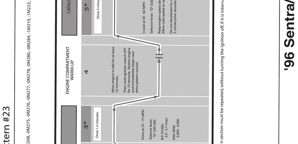
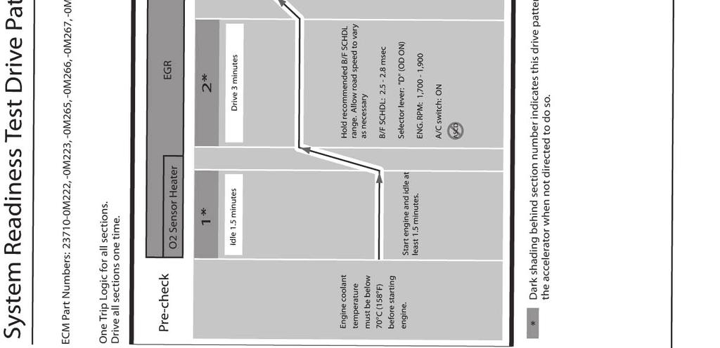
35 Pattern #23; 96 Sentra/200SX (GA16DE) A/T 35/58 NTB98-018g
SYSTEM READINESS TEST (SRT) DRIVE PATTERNS
 DRIVE PATTERNS") Classification: Reference: Date: EC98-001f NTB98-018f November 7, 2012 SYSTEM READINESS TEST (SRT) DRIVE PATTERNS This bulletin has been amended. Several Changes were made on page 9. Please discard all
Classification: Reference: Date: EC98-001f NTB98-018f November 7, 2012 SYSTEM READINESS TEST (SRT) DRIVE PATTERNS This bulletin has been amended. Several Changes were made on page 9. Please discard all
SYSTEM READINESS TEST (SRT) DRIVE PATTERNS
 DRIVE PATTERNS") Classification: Reference: Date: EC98-001c NTB98-018c January 3, 2002 SYSTEM READINESS TEST (SRT) DRIVE PATTERNS This amended version of NTB98-018b contains an updated Service Procedure and updated ECM
Classification: Reference: Date: EC98-001c NTB98-018c January 3, 2002 SYSTEM READINESS TEST (SRT) DRIVE PATTERNS This amended version of NTB98-018b contains an updated Service Procedure and updated ECM
DTC P1273 A/F SENSOR 1 MONITOR ITEM CONDITION SPECIFICATION
 Component Description DTC P1273 A/F SENSOR 1 The A/F sensor 1 is a planar dual-cell limit current sensor. The sensor element of the A/F sensor 1 is the combination of a Nernst concentration cell (sensor
READINESS MONITOR DRIVE PATTERN
 24 READINS MONITOR DRIVE PATTERN 1. PURPOSE OF READINS TTS The On-Board Diagnostic (OBD II) system is designed to monitor the performance of emission related components, and indicate any detected abnormalities
READINESS MONITOR DRIVE PATTERN
 1GR-FE ENGINE CONTROL SYSTEM SFI SYSTEM 25 Contents READINS MONITOR DRIVE PATTERN PURPOSE OF READINS TTS The On-Board Diagnostic (OBD II) system is designed to monitor the performance of emission related
ALTIMA; MIL ON P1273 (QR25 ENGINE) MAY BE CAUSED BY THE REAR O2 SENSOR
 MAY BE CAUSED BY THE REAR O2 SENSOR") Classification: Reference: Date: EC05-016a NTB06-039a May 17, 2006 2004 2005 ALTIMA; MIL ON P1273 (QR25 ENGINE) MAY BE CAUSED BY THE REAR O2 SENSOR This bulletin has been amended. The Claims Information
Classification: Reference: Date: EC05-016a NTB06-039a May 17, 2006 2004 2005 ALTIMA; MIL ON P1273 (QR25 ENGINE) MAY BE CAUSED BY THE REAR O2 SENSOR This bulletin has been amended. The Claims Information
PROCEDURE TO COMPLETE IAVL WHEN IDLE SPEED NEEDS TO BE REDUCED.
 Classification: Reference: Date: EC05-009 NTB05-067 October 5, 2005 PROCEDURE TO COMPLETE IAVL WHEN IDLE SPEED NEEDS TO BE REDUCED. APPLIED VEHICLES: All 2002 2005 models IF YOU CONFIRM The idle, in Park
Fixed Right First Time. Volvo Technicians, Service and Parts Managers
 Tech-Net Notes Fixed Right First Time Volvo Technicians, Service and Parts Managers NO: 25-19 DATE: 6-30-2004 MODEL: 960-S/V90/850/S70/V70/C70 M. YEAR: 1996-1998 SUBJECT: Establishing Readiness for OBD
2013 ALTIMA SEDAN WITH 4 CYL ENGINE; MIL ON WITH A/F SENSOR DTC STORED
 Classificatio n: Reference: Date: EC12-024b NTB12-085b April 4, 2013 2013 ALTIMA SEDAN WITH 4 CYL ENGINE; MIL ON WITH A/F SENSOR DTC STORED This bulletin has been amended in several areas to remove V6
2004 TITAN AND ARMADA; MIL "ON" WITH DTC P1031, P1051, P1148, P1168 A/F SENSOR HEATER / CLOSED LOOP
 Classification: Reference: Date: EC04-008a NTB04-032a October 29, 2004 2004 TITAN AND ARMADA; MIL "ON" WITH DTC P1031, P1051, P1148, P1168 A/F SENSOR HEATER / CLOSED LOOP This bulletin amends NTB04-032.
Computers and Control Systems: Monitors, Trips, Drive Cycles and Readiness Codes
 1998 Volvo V70 AWD L5-2.4L Turbo VIN 56 B5254T Page 1 Computers and Control Systems: Monitors, Trips, Drive Cycles and Readiness Codes Generic Drive Cycle Readiness Code Resetting Procedure (Generic Drive
Vehicle Level Technical Service Bulletins All Technical Service Bulletins Engine Controls - Engine Idle Speed 25RPM Too High
 Select Vehicle New TSBs Technician's Reference Component Search: Conversion Calculator 2005 Nissan-Datsun Maxima V6-3.5L (VQ35) Vehicle Level Technical Service Bulletins All Technical Service Bulletins
OBD II DRIVE CYCLE DATE: May, 2003
 Page 1 of 7 SUBJECT : OBD II DRIVE CYCLE DATE: May, 2003 No: MODEL: 1996 98 models CIRCULATE TO: [ ] GENERAL MANAGER [ ] PARTS MANAGER [X] TECHNICIAN [X] SERVICE ADVISOR [X] SERVICE MANAGER [X] WARRANTY
FRONTIER WITH QR25 ENGINE; DTC P0420 (TW CATALYST SYS-B1) STORED IN THE ECM
 STORED IN THE ECM") Classification: Reference: Date: EC10-008 NTB10-045 March 19, 2010 2005-2006 FRONTIER WITH QR25 ENGINE; DTC P0420 (TW CATALYST SYS-B1) STORED IN THE ECM APPLIED VEHICLE: 2005-2006 Frontier (D40) APPLIED
Classification: Reference: Date: EC10-008 NTB10-045 March 19, 2010 2005-2006 FRONTIER WITH QR25 ENGINE; DTC P0420 (TW CATALYST SYS-B1) STORED IN THE ECM APPLIED VEHICLE: 2005-2006 Frontier (D40) APPLIED
2007 SENTRA & VERSA; DTC P0031, P2A00, P1148
 Classification: Reference: Date: EC08-017a NTB08-074a April 27, 2009 2007 SENTRA & VERSA; DTC P0031, P2A00, P1148 This bulletin has been amended. The Claims Information and Service Procedure have been
VOLUNTARY SAFETY RECALL CAMPAIGN QUEST FUEL PUMP CONTROL MODULE
 Reference: NTB12-022a April 12, 2012 Date: VOLUNTARY SAFETY RECALL CAMPAIGN 2011-2012 QUEST FUEL PUMP CONTROL MODULE This bulletin has been amended. The NHTSA # and OWNER S LETTER have been added. Please
Technical Service Bulletin
 Number 02-36-030 Subject OBD-II READINESS TEST DRIVE CYCLE FOR 1996-1998 SONATA Date Model DECEMBER, 2002 1996-1998 SONATA DESCRIPTION: This TSB describes Drive Cycles which may assist the vehicle s OBD-II
2007 ALTIMA AND SENTRA; DTC P0128 THERMOSTAT FUNCTION
 Classification: Reference: Date: EC07-001a NTB07-020a April 23, 2007 2007 ALTIMA AND SENTRA; DTC P0128 THERMOSTAT FUNCTION This bulletin has been amended. Applied Vehicles has been amended to exclude Altima
MAXIMA MIL "ON" WITH FRONT O2 SENSOR DTC P0134, P0135, P0154, OR P0155
 Classification: Reference: Date: EC01-029 NTB02-002 January 1, 2002 2000-2001 MAXIMA MIL "ON" WITH FRONT O2 SENSOR DTC P0134, P0135, P0154, OR P0155 APPLIED VEHICLES: 2000-2001 Maxima (A33) SERVICE INFORMATION
GROUP 13Ab. 13Ab-2 CONTENTS TROUBLESHOOTING STRATEGY.. DATA LIST REFERENCE TABLE... 13Ab-29 TROUBLE CODE DIAGNOSIS...
 13Ab-1 GROUP 13Ab CONTENTS TROUBLESHOOTING STRATEGY.. 13Ab-2 DATA LIST REFERENCE TABLE... 13Ab-29 TROUBLE CODE DIAGNOSIS..... 13Ab-2 FAIL-SAFE FUNCTION REFERENCE TABLE........................ 13Ab-20 DIAGNOSTIC
DTC P0420 CATALYST SYSTEM EFFICIENCY BELOW THRESHOLD (BANK 1)
") DTC P0420 CATALYST SYSTEM EFFICIENCY BELOW THRESHOLD (BANK 1) 05195 05FNS02 MONITOR DESCRIPTION The ECM uses 2 sensors mounted before and after the threeway catalytic converter (TWC) to monitor its efficiency.
DTC P0420 CATALYST SYSTEM EFFICIENCY BELOW THRESHOLD (BANK 1) 05195 05FNS02 MONITOR DESCRIPTION The ECM uses 2 sensors mounted before and after the threeway catalytic converter (TWC) to monitor its efficiency.
PATHFINDER, QUEST, MURANO, MAXIMA, ALTIMA V6 CVT JUDDER AND DTC P17F0 OR P17F1 STORED
 Classification: Reference: Date: APPLIED VEHICLE: AT15-005b NTB15-015b September 10, 2015 PATHFINDER, QUEST, MURANO, MAXIMA, ALTIMA V6 CVT JUDDER AND DTC P17F0 OR P17F1 STORED This bulletin has been amended
ECM REPLACEMENT PROCEDURES
 Classification: Reference: Date: EC00-007c NTB00-052c April 16, 2004 ECM REPLACEMENT PROCEDURES ATTENTION: THIS BULLETIN HAS BEEN REVISED. The Service Procedures for replacing an ECM on an Applied vehicle
DTC P P0304 NO. 4-1CYLINDER MISFIRE, MULTIPLE CYLINDER MISFIRE. On Board Diagnosis Logic
 DTC P0300 - P0304 NO. 4-1CYLINDER MISFIRE, On Board Diagnosis Logic On Board Diagnosis Logic When a misfire occurs, engine speed will fluctuate (vary). If the engine speed fluctuates enough to cause the
Technical Service Information Bulletin
 Technical Service Information Bulletin August 4, 2003 Title: Models: 02 03 ES 300 & 04 05 ES 330 REVISION NOTICE: April 1, 2005: 2004 2005 model year ES 330 vehicles have been added to Applicable Vehicles.
ENGINE 01 02A 1. Toc of SCT ON-BOARD DIAGNOSTIC [ENGINE. Toc of SCT 01 02A ON-BOARD DIAGNOSTIC [ENGINE CONTROL SYSTEM (ZM)] 01 02A
![ENGINE 01 02A 1. Toc of SCT ON-BOARD DIAGNOSTIC [ENGINE. Toc of SCT 01 02A ON-BOARD DIAGNOSTIC [ENGINE CONTROL SYSTEM (ZM)] 01 02A](/thumbs/90/103285807.jpg "ENGINE 01 02A 1. Toc of SCT ON-BOARD DIAGNOSTIC [ENGINE. Toc of SCT 01 02A ON-BOARD DIAGNOSTIC [ENGINE CONTROL SYSTEM (ZM)] 01 02A") ENGINE 01 SECTION Toc of SCT ON-BOARD DIAGNOSTIC [ENGINE CONTROL SYSTEM (ZM)]...01-02A ON-BOARD DIAGNOSTIC [ENGINE CONTROL SYSTEM (FS)]...01-02B ON-BOARD DIAGNOSTIC [CRUISE CONTROL SYSTEM].......01-02C
ENGINE 01 SECTION Toc of SCT ON-BOARD DIAGNOSTIC [ENGINE CONTROL SYSTEM (ZM)]...01-02A ON-BOARD DIAGNOSTIC [ENGINE CONTROL SYSTEM (FS)]...01-02B ON-BOARD DIAGNOSTIC [CRUISE CONTROL SYSTEM].......01-02C
2002 ENGINE PERFORMANCE. Self-Diagnostics - RAV4. Before performing testing procedures, check for any related Technical Service Bulletins (TSBs).
.") 2002 ENGINE PERFORMANCE Self-Diagnostics - RAV4 INTRODUCTION NOTE: Before performing testing procedures, check for any related Technical Service Bulletins (TSBs). To properly diagnosis and repair this
2002 ENGINE PERFORMANCE Self-Diagnostics - RAV4 INTRODUCTION NOTE: Before performing testing procedures, check for any related Technical Service Bulletins (TSBs). To properly diagnosis and repair this
2013 ALTIMA V6 SEDAN AND PATHFINDER SHUDDER FROM TORQUE CONVERTER LOCK UP CLUTCH
 Classification: Reference: Date: AT13-007a NTB13-064a June 13, 2013 2013 ALTIMA V6 SEDAN AND PATHFINDER SHUDDER FROM TORQUE CONVERTER LOCK UP CLUTCH This bulletin has been amended to correct a typographical
Table of Contents 1. INTRODUCTION GENERAL INFORMATION-ABOUT OBDII/EOBD PRODUCT DESCRIPTIONS OPERATIONS...11
 Table of Contents 1. INTRODUCTION...1 2. GENERAL INFORMATION-ABOUT OBDII/EOBD...1 2.1 ON-BOARD DIAGNOSTICS (OBD) II...1 2.2 DIAGNOSTIC TROUBLE CODES (DTCS)...2 2.3 LOCATION OF THE DATA LINK CONNECTOR (DLC)...3
1GR-FE ENGINE CONTROL SYSTEM SFI SYSTEM
 134 1GR-FE EINE CONTROL SYSTEM SFI SYSTEM DTC P0136 Oxygen Sensor Circuit Malfunction (ank 1 Sensor ) DTC P0137 Oxygen Sensor Circuit Low Voltage (ank 1 Sensor ) DTC P0138 Oxygen Sensor Circuit High Voltage
1 of 13 10/17/2016 1:36 PM
 1 of 13 10/17/2016 1:36 PM DTC P2195 Oxygen (A/F) Sensor Signal Stuck Lean (Bank 1 Sensor 1) DTC P2196 Oxygen (A/F) Sensor Signal Stuck Rich (Bank 1 Sensor 1) DTC P2197 Oxygen (A/F) Sensor Signal Stuck
01 02B ON-BOARD DIAGNOSTIC [ENGINE CONTROL SYSTEM (FS)]
![01 02B ON-BOARD DIAGNOSTIC [ENGINE CONTROL SYSTEM (FS)]](/thumbs/80/80600627.jpg "01 02B ON-BOARD DIAGNOSTIC [ENGINE CONTROL SYSTEM (FS)]") ON-BOARD DIAGNOSTIC [ENGINE CONTROL SYSTEM (FS)] CONTROL SYSTEM WIRING DIAGRAM [FS]............................ 2 CONTROL SYSTEM DEVICE AND CONTROL RELATIONSHIP CHART [FS]........ 4 Engine Control System............
ON-BOARD DIAGNOSTIC [ENGINE CONTROL SYSTEM (FS)] CONTROL SYSTEM WIRING DIAGRAM [FS]............................ 2 CONTROL SYSTEM DEVICE AND CONTROL RELATIONSHIP CHART [FS]........ 4 Engine Control System............
STATE I/M PROGRAM ADVISORY BULLETIN
 ATTENTION: GENERAL MANAGER q PARTS MANAGER q CLAIMS PERSONNEL q SERVICE MANAGER q IMPORTANT - All Service Personnel Should Read and Initial in the boxes provided, right. STATE I/M PROGRAM ADVISORY BULLETIN
PRE CHECK DI 456. w/ Tachometer. w/o Tachometer. Hand held Tester AUTOMATIC TRANSMISSION (A340E, A340F) 2003 TOYOTA TACOMA (RM1002U) D10837 D00729
 2003 TOYOTA TACOMA (RM1002U) D10837 D00729") DI456 w/ Tachometer w/o Tachometer D10837 PRECHECK DI8Z403 1. DIAGNOSIS SYSTEM (a) Description When troubleshooting OBD II vehicles, the only difference from the usual troubleshooting procedure is that
DI456 w/ Tachometer w/o Tachometer D10837 PRECHECK DI8Z403 1. DIAGNOSIS SYSTEM (a) Description When troubleshooting OBD II vehicles, the only difference from the usual troubleshooting procedure is that
DI 3 ENGINE DIAGNOSTICS DI PRE CHECK
 FI0534 PRECHECK DI3 DI09603 1. DIAGNOSIS SYSTEM (a) Description When troubleshooting OBD II vehicles, the only difference from the usual troubleshooting procedure is that you connect to the vehicle the
TELEMATICS SERVICE INFORMATION
 Classification: Reference: Date: EL15-006g NTB15-049g March 21, 2016 TELEMATICS SERVICE INFORMATION This bulletin has been amended. The service information and procedures have been revised. Please discard
Date: Order No.: Supersedes: Group: 14
 Date: May 31, 2011 Order No.: S-B-14.00/17a Supersedes: S-B-14.00/17, dated February 2004 Group: 14 Revision a: Document revised SUBJECT: State I/M (emission inspection and maintenance) Facilities Incorporating
G - TESTS W/CODES - 2.2L
 G - TESTS W/CODES - 2.2L 1994 Toyota Celica 1994 ENGINE PERFORMANCE Toyota 2.2L Self-Diagnostics Celica INTRODUCTION If no faults were found while performing F - BASIC TESTING, proceed with self-diagnostics.
Powertrain DTC Summaries OBD II
 Powertrain DTC Summaries Quick Reference Diagnostic Guide Jaguar X-TYPE 2.5L and 3.0L 2002 Model Year Revised January, 2002: P0706, P0731, P0732, P0733, P0734, P0735, P0740, P1780 POSSIBLE CAUSES Revised
#97-T-20A: MIL (Service Engine Soon Telltale Lamp) On and EGR DTCs P0401, P0404, P0405, P1404 and/or P1406 in PCM Memory - (Jan 6, 2003)
 On and EGR DTCs P0401, P0404, P0405, P1404 and/or P1406 in PCM Memory - (Jan 6, 2003)") #97-T-20A: MIL (Service Engine Soon Telltale Lamp) On and EGR DTCs P0401, P0404, P0405, P1404 and/or P1406 in PCM Memory - (Jan 6, 2003) Subject: Malfunction Indicator Lamp (SERVICE ENGINE SOON Telltale
#97-T-20A: MIL (Service Engine Soon Telltale Lamp) On and EGR DTCs P0401, P0404, P0405, P1404 and/or P1406 in PCM Memory - (Jan 6, 2003) Subject: Malfunction Indicator Lamp (SERVICE ENGINE SOON Telltale
Mazda North American Operations Irvine, CA
 Service Bulletin Mazda North American Operations Irvine, CA 92618-2922 2004 Mazda Motor of America, Inc. Subject: ENGINE CRANKS NO START Bulletin No: 01-011/04 RX-8 - ENGINE CRANKS NO START BULLETIN NOTE
DIAGNOSIS SYSTEM DESCRIPTION EG2 170
 EG2170 DIAGNOSIS SYSTEM DESCRIPTION The ECM contains a builtin self diagnosis system by which troubles with the engine signal network are detected and a malfunction indicator lamp on the combination meter
DTC P0171 SYSTEM TOO LEAN (BANK 1) DTC P0174 SYSTEM TOO LEAN (BANK 2)
 DTC P0174 SYSTEM TOO LEAN (BANK 2)") 05498 DIAGNOSTICS DTC P0171 SYSTEM TOO LEAN (BANK 1) 05EXR06 DTC P0172 SYSTEM TOO RICH (BANK 1) DTC P0174 SYSTEM TOO LEAN (BANK 2) DTC P0175 SYSTEM TOO RICH (BANK 2) CIRCUIT DESCRIPTION The fuel trim is
05498 DIAGNOSTICS DTC P0171 SYSTEM TOO LEAN (BANK 1) 05EXR06 DTC P0172 SYSTEM TOO RICH (BANK 1) DTC P0174 SYSTEM TOO LEAN (BANK 2) DTC P0175 SYSTEM TOO RICH (BANK 2) CIRCUIT DESCRIPTION The fuel trim is
ALTIMA SEDAN, COUPE, AND HYBRID; ENGINE NO CRANK / NO START
 Classification: Reference: Date: EL10-030 NTB10-139 November 23, 2010 ALTIMA SEDAN, COUPE, AND HYBRID; ENGINE NO CRANK / NO START APPLIED VEHICLES: 2007 2010 Altima Sedan (L32) with CVT only 2008 2010
BATTERY TESTING: NISSAN ORIGINAL EQUIPMENT AND GENUINE NISSAN REPLACEMENT BATTERIES
 Classification: Reference: Date: EL99-016k NTB99-048k October 7, 2004 BATTERY TESTING: NISSAN ORIGINAL EQUIPMENT AND GENUINE NISSAN REPLACEMENT BATTERIES This bulletin has been amended. Please discard
Catalyst System Efficiency Below Threshold (Bank 1)
") 190 1NZ-FXE EINE CONTROL SYSTEM SFI SYSTEM DTC P0420 Catalyst System Efficiency Below Threshold (Bank 1) MONITOR DCRIPTION The ECM uses 2 sensors mounted before and after the three-way catalytic converter
190 1NZ-FXE EINE CONTROL SYSTEM SFI SYSTEM DTC P0420 Catalyst System Efficiency Below Threshold (Bank 1) MONITOR DCRIPTION The ECM uses 2 sensors mounted before and after the three-way catalytic converter
MIL ON WITH P0840/P0845 AND P0710
 Classification: Reference: Date: AT09-002a NTB09-044a August 26, 2011 MIL ON WITH P0840/P0845 AND P0710 This bulletin has been amended. ACTIONS, the NOTE under PARTS INFORMATION, a portion of the repair
DI 3 ENGINE DIAGNOSTICS DI00H 22 PRE CHECK
 PRECHECK DI3 DI00H22 1. DIAGNOSIS SYSTEM (a) Description When troubleshooting OBD II vehicles, the only difference from the usual troubleshooting procedure is that you connect to the vehicle the OBD II
I30 MIL "ON" WITH DTC P0420 STORED - THREE WAY CATALYST FUNCTION
 Classification: Reference: Date: EC00-025b ITB00-054b June 7, 2004 2000-2001 I30 MIL "ON" WITH DTC P0420 STORED - THREE WAY CATALYST FUNCTION IMPORTANT: THIS BULLETIN HAS BEEN REVISED. The Service Information
Powertrain DTC Summaries EOBD
 Powertrain DTC Summaries Quick Reference Diagnostic Guide Jaguar X-TYPE 2.0 L 2002.25 Model Year Refer to page 2 for important information regarding the use of Powertrain DTC Summaries. Jaguar X-TYPE 2.0
ALTIMA V6 SEDAN AND PATHFINDER; JUDDER DURING LIGHT ACCELERATION
 Classificatio n: Reference: Date: AT13-017 NTB13-086 September 10, 2013 2013-2014 ALTIMA V6 SEDAN AND PATHFINDER; JUDDER DURING LIGHT ACCELERATION APPLIED VEHICLES, VINS AND DATES: APPLIED TRANSMISSION:
GROUP 13Ab. 13Ab-2 CONTENTS TROUBLESHOOTING STRATEGY.. DATA LIST REFERENCE TABLE... 13Ab-28 TROUBLE CODE DIAGNOSIS...
 13Ab-1 GROUP 13Ab CONTENTS TROUBLESHOOTING STRATEGY.. 13Ab-2 DATA LIST REFERENCE TABLE... 13Ab-28 TROUBLE CODE DIAGNOSIS..... 13Ab-2 FAIL-SAFE/BACKUP FUNCTION TABLE........................ 13Ab-20 DIAGNOSTIC
2007 G35; CRUISE CONTROL SYMPTOMS WHEN TRAVELING DOWNHILL
 Classification: Reference: Date: EL07-022a ITB07-028a October 24, 2007 2007 G35; CRUISE CONTROL SYMPTOMS WHEN TRAVELING DOWNHILL The Applied VIN/Date, ACTION, Parts Information, Claims Information, Service
EG1 189 EFI SYSTEM 5S FE ENGINE DIAGNOSIS SYSTEM
 5SFE ENGINE EG1189 DIAGNOSIS SYSTEM DESCRIPTION The ECU contains a builtin selfdiagnosis system by which troubles with the engine signal network are detected and a CHECK engine warning light on the combination
Diag. Code 71 EGR System Malfunction CIRCUIT DESCRIPTION. TR-92 ENGINE TROUBLESHOOTING - Circuit Inspection
 TR-92 EINE TROUBLESHOOTI - Circuit Inspection Diag. Code 71 EGR System Malfunction CIRCUIT DESCRIPTION The EGR system is designed to recirculate the exhaust gas properly controlled according to the driving
Powertrain DTC Summaries EOBD
 Powertrain DTC Summaries Quick Reference Diagnostic Guide Jaguar S-TYPE V6, V8 N/A and V8 SC 2002.5 Model Year Refer to pages 2 9 for important information regarding the use of Powertrain DTC Summaries.
DI 244 DIAGNOSTICS AUTOMATIC TRANSMISSION DIB30 01 PRE CHECK
 DI244 DIAGNOSTICS PRECHECK DIB3001 1. DIAGNOSIS SYSTEM (a) Description When troubleshooting OBD II vehicles, the only difference from the usual troubleshooting procedure is that you connect to the vehicle
EXHAUST RATTLE / BUZZING NOISE
 Classification: Reference: Date: EM05-003e NTB05-021e March 10, 2010 EXHAUST RATTLE / BUZZING NOISE This bulletin has been amended. The title, ACTIONS, PARTS INFORMATION, and the SERVICE PROCEDURE have
Are you as confident and
 64 March 2007 BY BOB PATTENGALE Although Mode $06 is still a work in progress, it can be used to baseline a failure prior to repairs, then verify the accuracy of the diagnosis after repairs are completed.
DTC P0134 OXYGEN SENSOR CIRCUIT NO ACTIVITY DETECTED (BANK 1 SENSOR 1)
") 05 120 05CRQ 02 DTC P0134 OXYGEN SENSOR CIRCUIT NO ACTIVITY DETECTED (BANK 1 SENSOR 1) CIRCUIT DESCRIPTION Refer to DTC P0130 on page 05 101. DTC No. DTC Detecting Condition Trouble Area P0134 After engine
05 120 05CRQ 02 DTC P0134 OXYGEN SENSOR CIRCUIT NO ACTIVITY DETECTED (BANK 1 SENSOR 1) CIRCUIT DESCRIPTION Refer to DTC P0130 on page 05 101. DTC No. DTC Detecting Condition Trouble Area P0134 After engine
Document ID: General Motors Corporation. All rights reserved.
 Page 1 of 7 Document ID: 1274962 #02-06-01-016A: (MIL) Service Engine Soon Telltale Illuminated With DTCs P0171 and/or P0174 (Retorque Intake Manifold Vacuum Chamber Bolts, Install Vacuum Chamber Springs)
MURANO; AUTOMATIC BACK DOOR DOES NOT OPERATE AND RELATED DTCS
 Classification: Reference: Date: BT15-020b NTB15-073b March 22, 2016 2015-2016 MURANO; AUTOMATIC BACK DOOR DOES NOT OPERATE AND RELATED DTCS This bulletin has been amended. Changes have been made to all
Alternative Fuel Engine Control Unit
 1999 Chevrolet/Geo Cavalier (CNG) Alternative Fuel Engine Control Unit Table 1: AF ECU Function Parameters The (AF ECU) controls alternative fuel engine operation. The control unit monitors various engine
2.8 Liter VR6 2V Fuel Injection & Ignition, Engine Code(s): AAA m.y
: AAA m.y") 2.8 Liter VR6 2V Fuel Injection & Ignition, Engine Code(s): AAA m.y. 1996-1997 01 - On Board Diagnostic (OBD) On Board Diagnostic (OBD II) Malfunction Indicator Lamp (MIL) On Board Diagnostic (OBD II),
2.8 Liter VR6 2V Fuel Injection & Ignition, Engine Code(s): AAA m.y. 1996-1997 01 - On Board Diagnostic (OBD) On Board Diagnostic (OBD II) Malfunction Indicator Lamp (MIL) On Board Diagnostic (OBD II),
2009 MAXIMA STEERING COLUMN COMFORT ADJUSTMENT
 Classification: Reference: Date: ST09-005 NTB09-094 September 23, 2009 2009 MAXIMA STEERING COLUMN COMFORT ADJUSTMENT APPLIED VEHICLES: 2009 Maxima (A35) IF YOU CONFIRM The steering column power adjustment
QUICK REFERENCE INDEX
 Edition: January 2000 Revision: November 2000 Publication No. SM0E-1B15U2 QUICK REFERENCE INDEX All rights reserved. No part of this Service Manual may be reproduced or stored in a retrieval system, or
DTC P0102 Mass Air Flow (MAF) Sensor Circuit Low Frequency
 Sensor Circuit Low Frequency") Seite 1 von 5 Document ID# 187823 1998 Chevrolet/Geo Tahoe - 2WD Print DTC P0102 Mass Air Flow (MAF) Sensor Circuit Low Frequency Circuit Description The mass air flow (MAF) sensor is
Seite 1 von 5 Document ID# 187823 1998 Chevrolet/Geo Tahoe - 2WD Print DTC P0102 Mass Air Flow (MAF) Sensor Circuit Low Frequency Circuit Description The mass air flow (MAF) sensor is
PROBLEM SYMPTOMS TABLE
 3MZ-FE ENGINE CONTROL SYSTEM SFI SYSTEM 29 SFI SYSTEM PROBLEM SYMPTOMS TABLE Symptom Suspected area See page 1. Starter ST-8 Engine does not crank (Does not start) 2. ST relay ST-2 3. Park/neutral position
DTC P0102 Mass Air Flow (MAF) Sensor Circuit Low Frequency
 Sensor Circuit Low Frequency") Page 1 of 5 1997 Pontiac Grand Prix Grand Prix (VIN W) Service Manual Engine Engine Controls - 3.8L Diagnostic Information and Procedures Document ID: 106986 DTC P0102 Mass Air Flow (MAF) Sensor Circuit
Page 1 of 5 1997 Pontiac Grand Prix Grand Prix (VIN W) Service Manual Engine Engine Controls - 3.8L Diagnostic Information and Procedures Document ID: 106986 DTC P0102 Mass Air Flow (MAF) Sensor Circuit
Powertrain DTC Summaries EOBD
 Powertrain DTC Summaries Quick Reference Diagnostic Guide Jaguar X-TYPE 2.5L and 3.0L 2001.5 Model Year Revised January, 2002: P0706, P0731, P0732, P0733, P0734, P0735, P0740, P1780 POSSIBLE CAUSES Revised
DTC P0134 OXYGEN SENSOR CIRCUIT NO ACTIVITY DETECTED (BANK 1 SENSOR 1)
") 05114 DIAGNOSTICS 05CRQ04 DTC P0134 OXYGEN SENSOR CIRCUIT NO ACTIVITY DETECTED (BANK 1 SENSOR 1) CIRCUIT DESCRIPTION Refer to DTC P0130 on page 0596. DTC No. DTC Detecting Condition Trouble Area After
05114 DIAGNOSTICS 05CRQ04 DTC P0134 OXYGEN SENSOR CIRCUIT NO ACTIVITY DETECTED (BANK 1 SENSOR 1) CIRCUIT DESCRIPTION Refer to DTC P0130 on page 0596. DTC No. DTC Detecting Condition Trouble Area After
VOLUNTARY RECALL CAMPAIGN PASSENGER AIR BAG OCCUPANT CLASSIFICATION SYSTEM (OCS)
") Reference: NTB08-095c December 4, 2008 Date: VOLUNTARY RECALL CAMPAIGN 2007 2009 PASSENGER AIR BAG OCCUPANT CLASSIFICATION SYSTEM (OCS) This bulletin has been amended. Instruction for the AC adapter has
Reference: NTB08-095c December 4, 2008 Date: VOLUNTARY RECALL CAMPAIGN 2007 2009 PASSENGER AIR BAG OCCUPANT CLASSIFICATION SYSTEM (OCS) This bulletin has been amended. Instruction for the AC adapter has
Service Bulletin. DTC Detection Item Associated Monitor
 Service Bulletin 03-010 Applies To: All OBD II equipped models except SLX March 29, 2003 OBD II DTCs and Their Associated Monitors This is a list of all DTCs for all OBD II models. No one model has all
2UZ-FE ENGINE CONTROL SYSTEM SFI SYSTEM
 160 2UZ-FE EINE CONTROL SYSTEM SFI SYSTEM DTC P0171 System Too Lean (Bank 1) DTC P0172 System Too Rich (Bank 1) DTC P0174 System Too Lean (Bank 2) DTC P0175 System Too Rich (Bank 2) DCRIPTION The fuel
DRIVE CYCLES > JTEC > OBD-II Monitor Enabling Criteria RWD/4WD JTEC PCM Equipped Vehicles >
 Print 2002 Jeep Grand Cherokee 4.7L Eng Limited OBD-II DRIVE CYCLES DRIVE CYCLES > 1995-02 JTEC > OBD-II Monitor Enabling Criteria RWD/4WD JTEC PCM Equipped Vehicles > The following procedure has been
MAXIMA INTERMITTENT NO START
 Classification: Reference: Date: EC97-026 NTB97-057 September 15, 1997 1995-97 MAXIMA INTERMITTENT NO START This bulletin supersedes NTB96-103/EC96-012 dated October 23, 1996. Please discard NTB96-103/EC96-012.
CRUISE CONTROL SYSTEM
 CRUISE CONTROL CRUISE CONTROL SYSTEM CRUISE CONTROL SYSTEM PRECAUTION 1 1. HANDLING PRECAUTION FOR CRUISE CONTROL SYSTEM (a) Turn the cruise control main switch OFF when not using the cruise control system.
DTC P0171, P0172, P0174, or P0175
 Page 1 of 6 2009 Pontiac G8 G8 Service Manual Document ID: 2076050 DTC P0171, P0172, P0174, or P0175 Diagnostic Instructions Perform the Diagnostic System Check - Vehicle prior to using this diagnostic
ON-BOARD DIAGNOSTICS II SYSTEM. 5. Specified Data. Signal (V) Ignition SW ON (Engine OFF)
 Ignition SW ON (Engine OFF)") 1. ENGINE CONTROL MODULE (ECM) I/O SIGNAL OBD0092A Crankshaft Camshaft Mass air flow Throttle Signal (+) 8 0 7 +7 Sensor output waveform Signal ( ) 29 0 0 Shield 54 0 0 Signal (+) 7 0 7 +7 Sensor output
1. ENGINE CONTROL MODULE (ECM) I/O SIGNAL OBD0092A Crankshaft Camshaft Mass air flow Throttle Signal (+) 8 0 7 +7 Sensor output waveform Signal ( ) 29 0 0 Shield 54 0 0 Signal (+) 7 0 7 +7 Sensor output
CRUISE CONTROL SYSTEM
 Negative (-) Battery Terminal CRUISE CONTROL CRUISE CONTROL SYSTEM Cable System name METER / GAUGE SYSTEM D033496E01 CRUISE CONTROL SYSTEM PRECAUTION 1 1. DISCONNECT AND RECONNECT CABLE OF NEGATIVE BATTERY
A750F AUTOMATIC TRANSMISSION: AUTOMATIC TRANSMISSION SYSTEM (for 1GR-FE)... Model Year: 2007 Model: 4Runner Doc ID: RM000000W80023X
... Model Year: 2007 Model: 4Runner Doc ID: RM000000W80023X") Last Modified: 4-26-2007 Service Category: Drivetrain 1.6 C Section: Automatic Transmission/Transaxle Model Year: 2007 Model: 4Runner Doc ID: RM000000W80023X Title: A750F AUTOMATIC TRANSMISSION: AUTOMATIC
Last Modified: 4-26-2007 Service Category: Drivetrain 1.6 C Section: Automatic Transmission/Transaxle Model Year: 2007 Model: 4Runner Doc ID: RM000000W80023X Title: A750F AUTOMATIC TRANSMISSION: AUTOMATIC
ENGINE CONTROL SECTION EC CONTENTS
 ENGINE CONTROL SECTION EC CONTENTS PRECAUTIONS... EC-3 On Board Diagnostic (OBD) System of Engine... EC-3 Precaution... EC-3 PREPARATION... EC-6 Special Service Tools... EC-6 DESCRIPTION... EC-7 Description...
Shift Solenoid "B" Performance (Shift Solenoid Valve S2)
") 88 A750F AUTOMIC TRANSMISSION AUTOMIC TRANSMISSION SYSTEM DTC P0756 Shift Solenoid "B" Performance (Shift Solenoid Valve S2) DESCRIPTION The ECM uses signals from the output shaft speed sensor and input
88 A750F AUTOMIC TRANSMISSION AUTOMIC TRANSMISSION SYSTEM DTC P0756 Shift Solenoid "B" Performance (Shift Solenoid Valve S2) DESCRIPTION The ECM uses signals from the output shaft speed sensor and input
DTC P0171 SYSTEM TOO LEAN (BANK 1) DTC P0172 SYSTEM TOO RICH (BANK 1) DTC P0174 SYSTEM TOO LEAN (BANK 2) DTC P0175 SYSTEM TOO RICH (BANK 2)
 DTC P0172 SYSTEM TOO RICH (BANK 1) DTC P0174 SYSTEM TOO LEAN (BANK 2) DTC P0175 SYSTEM TOO RICH (BANK 2)") 05155 05NZ501 DTC P0171 SYSTEM TOO LEAN (BANK 1) DTC P0172 SYSTEM TOO RICH (BANK 1) DTC P0174 SYSTEM TOO LEAN (BANK 2) DTC P0175 SYSTEM TOO RICH (BANK 2) CIRCUIT DESCRIPTION These DTCs indicate that the
05155 05NZ501 DTC P0171 SYSTEM TOO LEAN (BANK 1) DTC P0172 SYSTEM TOO RICH (BANK 1) DTC P0174 SYSTEM TOO LEAN (BANK 2) DTC P0175 SYSTEM TOO RICH (BANK 2) CIRCUIT DESCRIPTION These DTCs indicate that the
EXTENDED STORAGE SWITCH AND BCM TRANSIT MODE
 Classification: Reference: Date: EL10-038f NTB10-124f February 10, 2012 EXTENDED STORAGE SWITCH AND BCM TRANSIT MODE This bulletin has been amended. The Adoption Date Table has been updated. No other changes
INDEX. 1.Safety Precautions and Warnings...3
 INDEX 1.Safety Precautions and Warnings...3 2. General Information...5 2.1 On-Board Diagnostics (OBD) II... 5 2.2 Diagnostic Trouble Codes (DTCs)... 6 2.3 Location of the Data Link Connector (DLC)...7
Inspection/Maintenance Evaporative Emission System Set
 Page 1 of 5 2001 Chevrolet S10 Pickup - 2WD Blazer, Bravada, Envoy, Jimmy, S10 Pickup, Sonoma VIN S/T Service Manual Engine Engine Controls - 2.2L L43 Diagnostic Information and Procedures Document ID:
A750E AUTOMATIC TRANSMISSION: AUTOMATIC TRANSMISSION SYSTEM (for 1GR-FE)... Model Year: 2007 Model: 4Runner Doc ID: RM000000XP101WX
... Model Year: 2007 Model: 4Runner Doc ID: RM000000XP101WX") Last Modified: 4-26-2007 Service Category: Drivetrain 1.6 C Section: Automatic Transmission/Transaxle Model Year: 2007 Model: 4Runner Doc ID: RM000000XP101WX Title: A750E AUTOMATIC TRANSMISSION: AUTOMATIC
Last Modified: 4-26-2007 Service Category: Drivetrain 1.6 C Section: Automatic Transmission/Transaxle Model Year: 2007 Model: 4Runner Doc ID: RM000000XP101WX Title: A750E AUTOMATIC TRANSMISSION: AUTOMATIC
For. Code Reader. User Manual
 For OBD2 Code Reader User Manual http://www.motodok.com Table of Contents 1. Description... 2 2. Features... 2 3. Getting Started... 3 1. Connect Code Reader to Vehicle's Test Connector... 3 2. Read Diagnostic
User s Manual XOB15091 OBD II / EOBD CODE READER. All Rights Reserved. Warranty and Service
 5. Warranty and Service 5.1 Limited One Year Warranty The manufacturer/supplier warranty provided to customers for this product will be free from all defects in materials and workmanship for a period of
 Verified Fix #1 Tool Data Diagnostic Trouble Code Information Report Customer #1 VIN: JT8BL69SX4G015327 Customer Name: Year: 2004 Customer Phone#: 123-123-1234 Make: Lexus Report#: 162 Model: GS 430 Date
1. OBD II Readiness Monitors An important part of a vehicle s OBD II system is the Readiness Monitors, which are indicators used to find out if all
 1. OBD II Readiness Monitors An important part of a vehicle s OBD II system is the Readiness Monitors, which are indicators used to find out if all of the emissions components have been evaluated by the
6.0L BUILT ON OR BEFORE 9/29/2003 DTCS P006A TSB OR P132B LACKS POWER, SURGE, OR FLUTTER AFTER FIELD SERVICE ACTION 06E17
 6.0L BUILT ON OR BEFORE 9/29/2003 DTCS P006A TSB 06-24-6 OR P132B LACKS POWER, SURGE, OR FLUTTER AFTER FIELD SERVICE ACTION 06E17 FORD: 2003-2004 Excursion, F-Super Duty ISSUE 3. Using IDS datalogger,
If a single test is completed entirely, but indicated as "not OK", a DTC will be stored in DTC memory. Check DTC Memory Page
 Page 1 of 43 01-77 Readiness code The readiness code appears as an 8-digit display in measuring value block 086, display field 1. Each of the 8 digits is allocated to a specific exhaust related system.
1 of 9 9/18/2017, 10:09 AM
 1 of 9 9/18/2017, 10:09 AM DTC P0505 IDLE AIR CONTROL VALVE (IACV) - AUXILIARY AIR CONTROL (AAC) VALVE Description SYSTEM DESCRIPTION This system automatically controls engine idle speed to a specified
DTC P20EE, P249D, P249E, or P2BAD
 Page 1 of 7 Document ID: 2614257 DTC P20EE, P249D, P249E, or P2BAD Diagnostic Instructions Perform the Diagnostic System Check - Vehicle prior to using this diagnostic procedure. Review Strategy Based
Chapter 20 OBD-II Diesel Monitors
 Light Vehicle Diesel Engines First Edition Chapter 20 OBD-II Diesel Monitors LEARNING OBJECTIVES (1 of 2) 20.1 Prepare for the Light Vehicle Diesel Engine (A9) ASE certification fuel system diagnosis and
DIAGNOSIS SYSTEM DESCRIPTION
 EFI SYSTEM FI21 DIAGNOSIS SYSTEM DESCRIPTION The ECU contains a builtin selfdiagnosis system by which troubles with the engine signal network are detected and a CHECK engine warning light on the instrument
P2000-NOX ABSORBER EFFICIENCY BELOW THRESHOLD
 - D - RAM 5 PICKUP - 6.7L CUMMINS TURBO DIESEL P-NOX ABSORBER EFFICIENCY BELOW THRESHOLD For a complete wiring diagram, refer to the Wiring Information. Theory of Operation The engine aftertreatment system
DIAGNOSTIC TROUBLE CODE CHART
 DI158 DIAGNOSTIC TROUBLE CODE CHART HINT: ENGINE (2JZGTE) Parameters listed in the chart may not be exactly the same as your reading due to the type of instrument or other factors. If a malfunction code