SOUTHERN REGIONAL POWER COMMITTEE BENGALURU
|
|
|
- Britton Sherman Weaver
- 5 years ago
- Views:
Transcription
1
2
3
4 SOUTHERN REGIONAL POWER COMMITTEE BENGALURU Minutes of the 45 th Meeting of Protection Coordination Sub-Committee (PCSC 45) of SRPC held on Introduction The 45 th meeting of Protection Coordination Sub-Committee (PCSC-45) was held on 25 June, 2015 in the Conference Hall of Southern Regional Power Committee, Bangalore. The list of participants is enclosed at Annexure-I. Shri S.R.Bhat, Member Secretary (MS), SRPC welcomed the Members and Participants to the meeting and briefed them on the following points: Congratulated Ms. J. Rexline Terese on assuming the charge of Chief Engineer (P&C), TANTRANSCO. POSOCO s taking over of the functions of the Grid Study Committee formed to facilitate study/ analysis by the to-be-appointed Consultant in compliance of MoP order dated As the Consultant s work would be shortly commenced, the furnishing of pending data inputs by SR-Constituents relating to the general protection philosophy followed by them & the relay settings data for the 25 substations identified in SR for audit by the Consultant, and Nodal Officer nomination by the States were brought to members attention. The salient points of the NLDC s communication dated addressed to RPC s and CERC (Annexure-II) on the events leading to separation of SR-grid from NEW-grid on and were briefed and proposed to be discussed later in the meeting. The NLDC s letter dated (Annexure-III) on the tripping of trunk transmission lines in the All India grid was briefed and proposed to be discussed later in the meeting. Brought to members attention the requirements of CERC Order dated on APTRANSCO s Petition No. 95/MP/2015 and CERC Order dated on TSTRANSCO s petition No. 83/MP/2015: 1. Time allowed for the completion of Phase-I and II remarks of protection audit of APTRANSCO is Time allowed for the completion of protection audit of TSTRANSCO is for Phase-I remarks and for Phase-II remarks. 3. SRPC is directed to monitor the status of completion of remarks in these substations vis-à-vis protection audit remarks in Protection Coordination Sub Minutes of the 45 th PCSC Meeting held on Page 1
5 Committee (PCSC) meetings. 4. SRPC is further directed to coordinate the periodic protection audit to be carried out in Southern Region after deliberations in SRPC and submit bi-monthly report to the Commission. In this regard, it was proposed to conduct a review audit on the similar lines of the earlier conducted audit (in 2012) including the missing requirements such as relay settings and try to identify the gaps in the system. However, as the appointment of Consultant in pursuance of MoP Order was underway, the details and schedule for the review audit would be finalized pending suitable inputs from the Consultant. In any case, it was decided to start this review audit covering all 220 kv & above stations in SR in a couple of months and carry out the same on revolving basis. 2. Confirmation of the Minutes of the 43 rd PCSC meeting held on SE (Protection), SRPC stated that the Minutes of the 44 th meeting of the PCSC had been circulated vide SRPC letter No. SRPC/SE-III/ PCSC 44/ 2015/ dated However, on account of (i) observations received from NTPC, Ramagundam (verbal communication) w.r.t. tripping of Ramagundam Chandrapur line 2, and (ii) typographical error under Digital Tele-Protection Coupler in the deliberations relating to SR and NEW grids separation on given at Sl. No. I (3) of the Annexure-III to the Minutes, the same were corrected as follows: (i) the statement Direct trip was not received at Ramagundam end due to PLCC channel fail during transmission of code. shall be replaced as Direct Trip was received at Ramagundam end (ii) the statement In SRPC meeting, it was agreed by EDs of SR-1 & SR-2 to extend the trip signals to Gajwel, NTPC- Ramagundam, Budidampadu (near Khammam) and Veltoor (instead of Tandur) as all are wide band points. shall be replaced as In SRPC meeting, it was agreed by EDs of SR-1 & SR-2 to extend the trip signals to Gajwel, Ramagundam Switching Station (Malayalapalli), Budidampadu (near Khammam) and Veltoor (instead of Tandur) as all are wide band points. Also in the diagram pertaining to Sl. No. I (3) of the Annexure-III to the Minutes, the lines marked NPS at Tiruvalam 400 kv station shall be read as Nellore (PG). With this, the Minutes of the 44 th meeting of the PCSC were confirmed. Minutes of the 45 th PCSC Meeting held on Page 2
6 3. Details of Grid Disturbances (GD s), Grid Incidents (GI s), Line Trippings due to PLCC maloperation, Auto-Reclose non-operation The tripping due to GD s, GI s, Auto Reclosure failure/ non-operation, and PLCC maloperation that had occurred during the period May - June, 2015 were discussed in the Meeting. The deliberations and recommendations of the PCSC-forum are enclosed at Annexure IV. 4. Status of pending PCSC recommendations The status of implementation of pending PCSC recommendations were discussed in the meeting. The constituents have been requested to kindly submit the status of their compliance latest by The updated status of the same as on is enclosed at Annexure V. 5. Remedial measures/ Action taken for the tripping incidents of the transmission elements under forced outage The tripping incidents of the transmission elements under forced outage for which the remedial measures/ actions taken still awaited were discussed in the Meeting. The Constituents have been requested to kindly furnish the remedial measures/ action taken in time so as to forward the same to Central Electricity Authority. The updated list of the same as on is enclosed at Annexure-VI. 6. Certificate for Healthiness of Batteries As per the MoP/ CEA direction given in pursuant to recommendations of the Enquiry Committee (NEW grid disturbance on 30 th & 31 st July, 2012), RPC s are required to obtain from their respective Constituents the monthly certificate for healthiness of batteries, installed at 220 KV and above voltage level Substations (for power supply to Relays, RTUs and PLCC equipment) and furnish the same to CEA/ MoP. With reference to above, the Constituents have been requested to submit the certificate on healthiness of batteries on monthly basis (i.e. status for a month may be sent by the 7 th day of the following month) to SRPC. The sought status for the month of May, 2015 has not been received from the following SR- Constituents: APGENCO (Thermal), TSGENCO (Hydro), KPTCL, TANGEDCO, PGCIL (SR-I), NLC, GMR, NTPL, CEPL, SEL. 7. Dynamic study data submission All SLDCs have been requested to direct the embedded IPPs connected at 220 kv and above voltage level to submit completed dynamic study format to SRPC, Secretariat. Constituents have been requested to submit the Dynamic study data at the earliest. Minutes of the 45 th PCSC Meeting held on Page 3
7 8. Network configuration changes As per the information furnished by SR-Constituents to the OCC forum in their 108 th Meeting held on (Minutes circulated on ), the following network configuration changes (additions/ deletions/ modifications of transmission elements) took place in the southern grid during the month of May, kv Mettur-Thiruvalam D/C commissioned on & by TANTRANSCO. 2X220 MVA,220 kv S/S at Nandyala is augmented to 3X220 MVA,220 kv S/S by APTRANSCO on MW Wind Generation capacity was added in Tamil Nadu during the month May Compliance of Hon ble CERC Orders 9.1 Petition No. 146/MP/2013 with I.A. 36/2013: Order dated Compliance of Regulations 5.2 (r) of the Grid Code: Issue regarding nonfurnishing of FIR / Trip Analysis Report, EL, DR, etc. was also highlighted. It is pointed out that the above reports are to be submitted / uploaded on SRLDC web application within 24 hours as mandated under IEGC / CEA Regulations. Implementation of Phase-I and Phase-II of Protection Audit Recommendations: All the constituents are requested to submit the updated status of the compliance (those who have not completed recommendations mentioned in the Phase I and Phase II) to SRPC Secretariat at the earliest. The following constituents are to submit the updated status of filing of petition/affidavit to SRPC Secretariat at the earliest: APTRANSCO. Compliance of Regulations 5.2 (e) & 5.2 (l) of the Grid Code and Regulation 3(1)(e) of CEA Grid Standards: The constituents are requested to strictly comply with these provisions by ensuring standard protections systems having the reliability, selectivity, speed and sensitivity to isolate the faulty equipment and protect all components from any type of faults, within the specified fault clearance time and providing protection coordination Ensuring proper maintenance of transmission lines and adopting best O&M practices: The constituents are requested to conduct line patrolling regularly as per the SRPC transmission line patrolling guidelines (available under the menu item "All Uploads Operation Miscellaneous Transmission Line Patrolling Protocol / Guidelines for Southern Region" on SRPC website). ( 9.2 Petition No. 167/Suo- Motu/2012: Order dated The Constituents are requested to follow approved protection philosophy ISTS licensees are requested to submit details of updated distance protection relay Minutes of the 45 th PCSC Meeting held on Page 4
8 setting of all inter-regional lines to POSOCO & RPCs. All SLDCs are requested to install/activate sound recording system in their control rooms within three months from the date of issue of this order. The Constituents are requested to submit the progress of implementation to SRPC and SRLDC as specified in the Hon'ble CERC Order. 9.3 Petition No. 263/MP/2012: Order dated Constituents are requested to implement the quantum of relief by AUFR and df/dt relays by identifying additional feeders and keep them functional within one month of issuing this order. SLDCs are also requested to map these relays on their respective SCADA system within three months of issuance of this order. The Constituents are requested to submit the progress of implementation to SRPC and SRLDC as specified in the Hon'ble CERC Order. 9.4 Petition No. 374/MP/2014: Date of hearing All Southern Region Constituents had been directed to file the status of implementation of protection system in their respective system to Hon ble CERC by APTRANSCO s Petition No.95/MP/2015: Order dated It was noted in the Analysis and Decision part of the Order that: 8. Noting the submissions of the petitioner, SRPC and SRLDC and activities initiated by the petitioner for procurement of materials required for implementation of the remarks of protecting audit, we allow time to the petitioner till for completion of our directions in order dated in Petition No. 146/MP/ SRPC is directed to monitor the status of completion of works relating to protection audit remarks in respect of 7 nos 400 kv sub-stations and 11 nos 220 kv sub-stations of APTRANSCO, protection audit remarks in Protection Coordination Sub-Committee (PCSC) meetings and coordinate the periodic protection audit to be carried out in Southern Region after deliberation in SRPC and submit bi-monthly report to the Commission. 9.6 TSTRANSCO s Petition No.83/MP/2015: Order dated It was noted in the Order that: 12. Noting the submission of the petitioner, SRLDC and SRPC and considering the actions already initiated by the petitioner for implementation of works relating to protection audit, we allow time till and for implementation of Phase-I and Phase -II works respectively. The petitioner is directed to submit affidavit confirming the completion of phase I of protection audit remarks by and phase-ii of protection audit remarks by Minutes of the 45 th PCSC Meeting held on Page 5
9 13. SRPC is directed to monitor the status of completion of remarks in these substations vis-à-vis protection audit remarks in Protection Coordination Sub Committee (PCSC) meetings. SRPC is further directed to coordinate the periodic protection audit to be carried out in Southern Region after deliberation in SRPC. 10. Nomenclature for naming various files uploaded in Web based Tripping Monitoring System of SRLDC Portal The nomenclature to be followed by the Constituents in naming various files (FIR, DR, EL, TR) corresponding to a tripping incident was brought out in the SRPC letter No. SRPC/ SE-III/ PCSC-45/ dated (copy enclosed at Annexure-VII). As illustrated therein, the user entered part-name is proposed to be given by the user (Sender/ Receiver) as per the format given below: Transmission Element Transmission line Inter-connecting Transformer Generating Transformer Generating Unit File name to be given by the user SSN_DSN_line# SSN_ICT# SSN_GT# SSN_Unit# While following the above nomenclature, the users are however at liberty to append additional details like file_type (FIR/DR/EL/TR) as part of file name to distinguish various files (FIR, DR, EL, TR) corresponding to a tripping event at their end. Then, the format for the user entered part-name gets modified as follows: Transmission Element Transmission line Inter-connecting Transformer Generating Transformer Generating Unit File name to be given by the user SSN_DSN_line#_FT SSN_ICT#_FT SSN_GT#_FT SSN_Unit#_FT Where, SSN = Source Station Name/ From end Station Name/ Sending end Station Name DSN = Destination Station Name/ To end Station Name/ Receiving end Station Name FT = File Type (FIR/ DR/ EL/ TR) Minutes of the 45 th PCSC Meeting held on Page 6
10 11. Date & Venue of the next Meeting It is informed that the 46 th PCSC meeting would be held on (Thursday) at hrs at SRPC Secretariat, Bengaluru. ***** Minutes of the 45 th PCSC Meeting held on Page 7
11 Annexure-I
12 Annexure-I
13 Annexure-I
14 Annexure-I
15 Annexure-I
16 Annexure-I
17 Annexure-II
18 Annexure - 1 Annexure-II NEW and SR Grid Separation on at 19:19 hrs NEW Grid and SR Grid are synchronized through 2 X S/c 765 kv Sholapur Raichur lines. On 24 th May 2015 the two grids got de-synchronized at 19:19 hrs. Although the grids got desynchronized at 19:19 hrs the chain of trippings started at 17:12 hrs only. 1. Antecedent conditions (at 17:10 hrs) The various inter regional flows and critical line loadings were as follows: Talcher Kolar HVDC flow = 2000 MW Bhadravati HVDC flow = 1000 MW Gazuwaka HVDC flow = 650 MW Total Sholapur Raichur flow = 250 MW Wardha - Parli flow = 1120 MW SR Demand Met = MW SR Generation = MW NEW grid Demand = MW Weather = No major thunderstorm reported 2. Tripping at Ramagundam Thermal Power Station (at 17:11 hrs) At 17:11 hrs, 400 kv Bus 1 at Ramagundam TPS tripped along with 400 kv Ramagundam Gajwel and Ramagundam Bhadravati 2. The reason of tripping of 400 kv Ramagundam Bhadravati 2 was maloperation of line reactor PRV at Bhadravati end while 400 kv Bus 1 and Ramagundam Gajwel tripped due to LBB operation of 400 kv Ramagundam - Gajwel. The delayed fault clearance at Ramagundam can be seen in the PMU plot. The fault was cleared after 160 milli seconds. Due to tripping of one of the two lines from Bhadravati to Ramagundam the flow on the other line reached 1000 MW. The line is of twin Moose conductor type and the other circuit could not have been allowed to carry such high flow continuously. Therefore flow in Bhadravati HVDC was reduced to 600 MW. Talcher Kolar HVDC was increased to 2300 MW from 2000 MW. It is usually a practice that Talcher Kolar HVDC power flow can be made above 2000 MW for a maximum period of 10 hours in a day. On 24 th May 2015 the flow had not been increased beyond 2000 MW at all so there was plenty of margin. The objective was to maintain power flow in 765 kv Sholapur Raichur at safe levels. Later clearance was received from Bhadravati to charge 400 kv Bhadravati Ramagundam 2 and code was issued at 1841 hrs but there was delay in charging of the line from Ramagundam end.

19 Annexure-II 17:11: :11: Tripping at 400kV Tiruvelam substation at 19:13 hrs Y phase CT failure occurred in 400kV Alamathy-2 Bay at Tiruvelam substation (line yet to be commissioned and bay kept in charged condition for keeping dia complete). Busbar protection operated at Tiruvelam substation and cleared the fault. The bus coupler breaker connecting the Tiruvelam (PG) and Tiruvelam (TN) did not trip after operation of bus-bar protection and same needs further investigation. 400kV Chitoor-Tiruvelam (PG) line-1&2 got tripped from Chitoor end due to operation of overcurrent protection in Y phase. The over current protection was inadvertently enabled in distance relay at Chitoor. It was confirmed later that the over current protection has since been disabled. It is observed from negative and zero sequence current plots that the 1 st fault cleared in time and there was a delayed clearance during the 2 nd fault i.e. in 240 ms. 2 nd Fault 1 st Fault

20 Annexure-II Tripping at Tiruvalam S/S 4. Tripping/ generation reduction of Units in Southern region The flow in 765 kv Sholapur Raichur was being maintained at normal levels by controlling the drawl of SR constituents and raising the power order in Talcher Kolar HVDC to 2300 MW. Parallely the restoration of 400 kv Ramagundam Bhadravati was being taken up so that flow on Bhadravati HVDC could be restored to normal levels. But these actions by the system operator at NLDC were effectively nullified by consequent tripping of generators in Southern Region. Sl. Power Station Time Generation loss Reason No 1 NCTPS Unit-1 19:14 hrs 475 MW Tripped due to ID fan trip due dip in auxiliary voltage 2 MEPL Unit-1 19:14 hrs 135 MW Due to tripping of coal mill due to due to dip in auxiliary voltage 3 Vallur Unit-3 19:15 to 19: MW Generation reduction of 200MW occurred due to tripping of ID fan 4 Krishnapatnam Unit-1 19:17 hrs 550 MW Due to operation of generator protection 5 Raichur Unit-8 19:19 hrs 225 MW Tripped due operation of generator overvoltage (After desynchronization) Total 1585 MW Due to these consequent tripping of units in Southern Region flow in Sholapur Raichur started increasing. Also since the trippings occurred in quick succession the operator and the constituents could not take any immediate action. Only the primary response of the generators helped the

21 Annexure-II system somewhat. The flow on each circuit of Sholapur Raichur rose above 750 MW each causing SPS-1 to operate. SPS-1 tripped load connected to Trip Signal 3 of Kolar. 5. Tripping of HVDC Talcher-Kolar Pole-1&2 at 19:18 Hrs As per details received from Kolar station, Valve cooling tower fan fault alarm observed at 19:13: hrs and also three consecutive commutation failures were observed (Pole trips if there are 6 commutation failure consecutively within 1sec). Valve cooling tower fan tripped at 19:18: hrs. It was verbally informed that the Valve cooling tower fan could not re-start due to problem in control circuit. Due to tripping of Valve cooling tower fans the inlet temperature of valve cooling increased to trip level and both Poles tripped. Pole-1 got blocked at hrs and Pole-2 got blocked at Hrs. 2 nd pole went to metallic return mode and after 16.3 sec of tripping of pole-1, pole-2 also got blocked. SPS signal -1 & 2 of Talcher-Kolar HVDC got operated resulting in load shedding. As per envisaged scheme Trip Signal 3 should have provided additional load relief but Trip Signal 3 had already operated due to overloading of Sholapur Raichur. At Talcher, generation backing was done automatically in Talcher Unit 5 & 6, Sterlite Unit 4 and GMR of the order of 670 MW. There was no tripping of Talcher Unit 6 (as envisaged) and Manual backing was accomplished in JITPL of the order of 100 MW.


22 Annexure-II 6. Tripping of 765kV Solapur-Raichur line-1&2 at 19:19 hrs The flow on 765kV Solapur-Raichur line-1&2 was gradually increasing due to tripping of generating units in Southern Region. The flow on 765 kv Sholapur Raichur lines prior to tripping of HVDC Talcher-Kolar and units at Krishnapatnam and RTPS was 600MW each. The loss of HVDC Pole-1&2 carrying 2300MW generation loss at RTPS (225MW) and at Krishnapatnam (550MW) aggravated the situation and flow on 765kV Raichur-Solapur line-1&2 went up to 1600MW (each). Tripping of Sholapur - Raichur Tripping of HVDC Talcher - Kolar Tripping of Krishnapatnam The power flow on 765kV Solapur-Raichur line-1&2 went upto 1600MW and lines tripped after 8 seconds i.e., at 19:19: hrs due to mal-operation of SPS-7 for contingency of 765kV Raichur- Solapur lines. The SPS-7 contingency deals with, in case of outage of one of the circuits, tripping of the other Sholapur - Raichur line when current exceeds 800 Amp (1000 MW) from Sholapur to Raichur direction. SR and NEW grid got separated after tripping of 765kV Solapur-Raichur lines. Southern region frequency dipped to 49.19Hz after system separation leading operation of df/dt protection due to which the southern region frequency got restored to 49.8 Hz after separation from NEW grid. Load shedding due to df/dt operation was reported from AP, Karnataka, Tamilnadu and Kerala. The details of exact quantum of relief are to be furnished by states. The relief obtained from SPS operation, df/dt and UFR operation averted a major disturbance in SR grid.
23 Annexure-II From Negitive and zero sequence current plots of 400kV Sriperambadur-Kolar line, it can be observed that there was no fault in the system during the interval of tripping of HVDC Talcher-Kolar and 765kV Solapur- Raichur lines. 7. Resynchronization of NEW and SR grid Efforts to re-synchronize the two grids were started immediately after separation of the grids. The frequencies of the two grids were brought nearby by controlling generation in WR and SR. The two lines (765 kv Sholapur Raichur 1&2) were charged from Sholapur and open at Raichur end only. Since earlier too synchronization of the grids has been done from Sholapur end only so the lines were opened from Sholapur end and again charged from Raichur end. Later efforts were made to bring the frequencies of the two grids to 50 Hz. Finally the two grids were synchronized at Sholapur at 20:49 hrs.
 before finally stabilizing at 50 MW towards SR. The angular separation during the synchronization was as shown: 200 150 100 50 0-50 -100-62.92 degree* at 20:48:42.280 (* Raichur w.")
24 Annexure-II 2773 MW to MW After the synchronization it was observed that the flow on Sholapur Raichur has shown large variation from 2773 MW per circuit (towards SR) to 2051 MW per circuit (towards NEW grid) before finally stabilizing at 50 MW towards SR. The angular separation during the synchronization was as shown: degree* at 20:48: (* Raichur w.rt. Raipur) :48: :48: :48: :48: :48: :48: :48: :48: :48: :48: :48: :48: :48: :48: :48: :48: :48: :49: :49: :49: :49: :49: :49: :49: :49: :49: :49: :49: :49: :49: :49: :49: :49: :49:21.200
25 Annexure-II 8. Restoration details The tripped elements were restored as shown: Sl. No Element Restoration time 1 400kV Ramagundam-Bhadrawati-2 19:31 hrs on HVDC Talcher-Kolar Pole-1 19:46 hrs on HVDC Talcher-Kolar Pole-2 19:48 hrs on kV Raichur-Sholapur line-1 20:49 hrs on kV Raichur-Sholapur line-2 21:19 hrs on kV Chitoor-Tiruvelam (PG) line-1 21:35 hrs on kV Chitoor-Tiruvelam (PG) line-2 21:36 hrs on Raichur TPS unit-8 21:38 hrs on NCTPS ST2 Unit-1 22:55 hrs on MEPL Unit-1 01:55 hrs on
 The various inter regional flows and critical line loadings were as follows: Talcher Kolar HVDC flow = 1500 MW Bhadravati HVDC flow = 1000 MW Gazuwaka HVDC flow =")
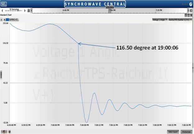
26 Annexure - 2 Annexure-II NEW and SR Grid Separation on at 17:00 hrs 1. Antecedent conditions (at 16:50 hrs) The various inter regional flows and critical line loadings were as follows: Talcher Kolar HVDC flow = 1500 MW Bhadravati HVDC flow = 1000 MW Gazuwaka HVDC flow = 650 MW Total Sholapur Raichur flow = -200 MW SR Demand Met = MW SR Generation = MW NEW grid Demand = MW Weather = Thunderstorms reported in vicinity of Sholapur 2. Brief Details: SR and NEW grid got separated occurred at 17:00:27 Hrs due to tripping of both 765 kv Sholapur- Raichur lines. 765 kv Sholapur- Raichur line-2 tripped on B-N fault at 16:59:20 Hrs. 765 kv Sholapur- Raichur line-2 tripped on Y-N fault at 17:00:27 Hrs. During synchronization of NEW and SR grids through 765 kv Raichur-Sholapur line-1, SPS-1 for Raichur-Solapur lines got operated as flow on line went to 3050 MW during 1 st swing. The grid de-synchronization is as depicted below: Tripping of Sholapur Raichur circuit 2 Tripping of Sholapur Raichur circuit 1 and grid separation
27 Annexure-II 3. Tripping of 765 kv Sholapur- Raichur line-2 at 16:59:18 hrs: From the above plot, we can observe that B-N fault was occurred. Auto reclose operated but due to persistent fault, line tripped. 400 kv Somanahalli-Hosur Sequence current Presence of negative and zero sequence also support the presence of phase to ground fault in the system. 765 kv Sholapur-Raichur MW flow
28 Annexure-II Before tripping of 765 kv Sholapur-Raichur -2, the flow on each circuit was 100 MW towards WR. After tripping of line-2, flow on line-1 went to 200 MW (SR export). 4. Tripping of 765 kv Sholapur- Raichur line-1 at 17:00:25 hrs Again it has been inferred that Y-N fault has occurred. Auto reclose has operated but due to persistent fault line has tripped. 400 kv Somanahalli-Hosur Sequence current Once again the presence of negative and zero sequence also support the presence of phase to ground fault in the system.
29 Annexure-II 765 kv Sholapur-Raichur MW flow 5. Re-Synchronisation of the grids 765 kv Raichur Sholapur Circuit 1 was taken in service at 19:00 hrs. The synchronisation was done at Sholapur end only. Immediately after the synchronization a high flow (the first swing was of 5700 MW) was once again observed in 765 kv Sholapur Raichur line. This caused the operation of SPS due to overloading of the line. 765 kv Sholapur Raichur 2 was charged and synchronized at 19:26 hrs. The angular plot during the re-synchronisation was as shown:
30 Annexure-II
31 Annexure - 3 Annexure-II NLDC Observations and Feedback regarding the two incidences of NEW and SR grid separation on 24 th May 2015 and 31 st May 2015 NEW and SR grid have been synchronized first time on 31 st December 2013 through 765 kv Sholapur Raichur line and at present the entire country operates as a single synchronous grid. NEW and SR grids got separated on 24 th May 2015 and 31 st May 2015 due to tripping of the two interconnecting 765 kv Sholapur Raichur lines. On the first occasion the grids got separated due to mal-operation of SPS-7 at Raichur end after tripping of HVDC Talcher Kolar and on the second occasion the lines tripped in quick succession due to persisting fault in the lines. The NLDC observations are as follows: 1. In the first incident it was observed that after the tripping of Talcher Kolar bipole load relief was obtained as per designed SPS action but the consequent Raichur Sholapur overloading could not be contained as all SPS actions were exhausted. Thus after separation SR grid frequency fell to Hz and any further dip was prevented by UFR and df/dt action. This strongly suggests that SPS load relief from Sholapur Raichur tripping and Talcher Kolar tripping needs to be independent. Also as per SPS scheme for Talcher Kolar bipole tripping Talcher Unit 6 is supposed to trip but in this case Talcher Unit tripping did not take place. This requires thorough investigation and root cause analysis. 2. On the first occasion we can also see that a series of relatively manageable events have occurred in quick succession which has caused the system to be virtually unmanageable for a system operator. Another issue that strikes at a glance is that a number of units as well as Talcher Kolar HVDC link have cited dip in auxiliary voltage (due to delayed fault clearance at Tiruvelam S/S) as the reason for tripping. In the 44 th Protection Sub-Committee meeting of the SRPC it was decided to implement time delay in VFD speed sensor for avoiding such sequential tripping in future. 3. As per the design scheme of SPS for WR-SR link, SPS-7 is to operate in case of line flow exceeding 1000 MW with outage of one of the circuits of Sholapur Raichur. The SPS is disabled in case of both lines being in service. This reason for the same was deliberated on in the 44 th Protection Sub-Committee meeting of the SRPC and it was explained that auxiliary contacts for one of the line isolator had mal-functioned causing the SPS-7 to maloperate. The issue has been rectified since. 4. On both the occasions immediately after the synchronization the load flow in Sholapur Raichur was observed to be quite high, in the order of 2500 MW. Upon further investigation it was discovered that the synchronization was done at an angular difference well beyond permissible limit (as already brought out in the report). Consequently POWERGRID has taken shutdown of the Raichur Sholapur I on 04 th June 2015 to further investigate the reason for this rough synchronization but is yet to share any further details. 5. The fact that in spite of having two 765 kv synchronizing links between NEW and SR grids the grids are getting separated is also an eye-opener. Especially since the two 765 kv lines are on independent towers. In future with more 765 kv double circuit lines coming up the impact of contingency of any such line in any corridor can be a matter of serious concern for the system operator.
32 Annexure-III
33 Annexure-III
34 Annexure-III
35 Annexure-III
36 Annexure-IV Grid Occurrences I. GRID DISTURBANCES (GD s): 1 Complete outage of 220kV Peenya substation of KPTCL (GD-1) (i) Date and Time of Event at 17:53 Hrs (ii) Location Peenya station (iii) Reported Disturbance / Fault All connected lines to 220kV Peenya substation, viz., Nelamangala -2,3&4, Subramanyapura, Hebbal and NRS feeders tripped during the incident. Delayed clearance was observed from synchrophasor data (iv) Load Loss 300 MW (v) Category GD-1 SLD: Dobaspet distance trip (power swing trip) Nelamangala at-fault: power flow reversed despite absence of source at south bus Pre-fault: power flow Peenya 220 kv trip O/C trip CPRI (north) A/R (south) A/R NO NO Hebbal A/R NRS Hoody A/R Subramanyapura 3 x 150 MVA, with tertiary 1 x 67.5 MVA 66 kv Deliberations: 1 Grid Occurrences of 45 th PCSC Meeting held on
37 Annexure-IV KPTCL: Set-up: On the day of fault, Peenya 220 kv north bus was with Hebbal, Nelamangala (1) and NRS feeders; Peenya 220 kv south bus was connected with 4 transformers (3x150 MVA, 1x67.5 MVA), three lines from Nelamangla (2,3,4) along with Subramanyapura feeder. Bus coupler between north and south buses was in closed condition. Power was being fed by Nelamangla lines to Peenya buses. The Nelamangala-Hoody line was kept open at Hoody end; and the Hoody Hebbal line was kept open at Hebbal end. There was a line-to-ground fault on Nelamangla Dobaspet feeder, and got cleared on operation of back-up protection (Over current earth fault relay) at Nelamangala end in about 300 ms. During this short time, there was reversal of power flow on the Nelamangla Peenya lines 2,3 &4, i.e. from Peenya to Nelamangla on account of acting of tertiary winding of the transformers at Peenya south bus as a shunt to the fault (thus contributing to the fault point) even though there was no source on the south bus of Peenya. The numerical relay (Siemens make, 7SA522) on Nelamangala Peenya lines at Nelamangala end have a feature to issue an instantaneous trip command on account of power swing when the locus of relay moves from positive (1 st quadrant) to negative (4 th quadrant). As this feature was in enabled condition, the reversal of power flow on Nelamangla Peenya lines 2,3 &4 resulted in tripping of the same at Nelamangala end on Power Swing Trip. It was informed that this feature was not present in the relays at Peenya end. As a result, the Nelamangala Peenya line-1 had to feed both north and south buses at Peenya that resulted in over loading of the bus coupler and finally tripping it. Remedial Action: On all four Nelamangala- Peenya lines, the power swing instantaneous trip feature due to change of quaderant has been deactivated in the relays at Nelamangala end. The non-sensing of the fault on Nelamangala - Peenya 220 kv line at Peenya end was traced to the low set values of the resistive reach in the corresponding distance relay, which were subsequently increased to a suitable value. It was noted that there also existed an additional path for power reversal through Nelamangala Hoody-Hebbal Tie Peenya North Bus Bus Coupler Peenya South Bus Nelamangala 2 Complete outage of MEPL power station (GD-1) (i) Date and Time of Event at 20:38 hrs (ii) Location (iii) Reported Disturbance / Fault Y phase CT failure at MEPL led to tripping of 400kV NPS-MEPL, 400kV SEPL-MEPL line and Unit-2 at MEPL. Uni-1 was not in service at the time of tripping (iv) Generation Loss 150MW (v) Category GD-1 2 Grid Occurrences of 45 th PCSC Meeting held on
38 Annexure-IV SLD: MEPL SEL Over freq. trip LBB trip O/C trip Nunna Z 2 trip NPS Nellore 400 (PG) O/C trip? 400 kv 765 kv Gooty (PG) 765 Tiruvalam Almathy Sriperumpudur Deliberations: Kurnool 765 Root cause: Insulation Failure of Primary winding (explosion) of Y-Phase metering-ct at MEPL end on MEPL NPS 400 kv S/C line. MEPL-NPS 400 kv S/C line: At MEPL end: Set-up: MEPL power plant is with 2x150 MW Units; Unit-2 was under shut down and 3 Grid Occurrences of 45 th PCSC Meeting held on
39 Unit-1 was in service. The plant has one 400 kv evacuating line to NPS and another tie-line to adjacent SEL power plant; both the lines are in service. One and half breaker switching scheme with 5 CTs is being used. As per TR of MEPL, line tripped at MEPL due to blast of Y-ph metering CT. The line opened in Zone 1, DPR and the fault got cleared in about 40 ms. However, three phase trip occurred after 200 msec (i.e., at 20:38: hrs) due to bus bar protection relay operation. It was explained by MEPL representative that Tie-CB (405) Bay Control Unit (BCU) which has nothing to do with bus bar protection mal-operated and sent Line Breaker (405) LBB operation signal over the Goose communication to Bus bar protection relay. Carrier was sent to NPS end on both the channels immediately after occurrence of fault. MEPL requested NPS not to reset the PLCC counter reading after every trip as reported by PGCIL to troubleshoot PLCC issues that are being faced on the line. MEPL also informed that: Secondary damage to Line#2 metering CVTs was observed due to CT explosion, which needs to be replaced/repaired and tested before putting them in service. One of the Y-Phase Isolator support insulator of L Isolator got damaged which needs to be replaced. Remedial Action: As the Tie-CB BCU relay is not supposed to send any signal to Busbar protection relay, the matter has been referred to M/s ABB for resolution. MEPL representative also stated that according to OEM (ABB) report, the CT failure was attributed to operating CT above 420 kv voltage, which is the highest system operating system voltage. To this, SRPC requested MEPL to approach SP&PA Division of CEA for suitable remedial measures. At NPS end: As per TR of NPS, line tripped at NPS end due to distance relay operation in Zone-2. No carrier from MEPL was received at NPS end, and the Main CB (407) of MEPL line got tripped in Zone-2 (0.3 sec delay). It was reported by PGCIL that at NPS, the PLCC counter reading is reset (made to zero) immediately after every tripping in order to visualize clearly how many Tx and Rx signals were sent and received for that particular fault which is being recorded. MEPL SEL 400 kv S/C line: As per TR of MEPL, LBB relay operation subsequent to Y-ph CT blast at MEPL opened main-cb on MEPL-SEL line at MEPL. However as the corresponding tie-cb was in closed condition, the line tripped at SEL end only due to instantaneous OC relay operation. It was noted that as the line between SEL and MEPL is of very short length (around 1.5 km), line differential protection has been employed as primary protection for the line with OC protection as back-up. SRLDC: The over current protection at SEL end being back up protection, its instantaneous operation is not desirable, and should be coordinated with zone-2 setting of adjacent lines. KPTCL: In line differential protection, back up O/C protection is invoked only in case of communication failure, otherwise not. SRPC: Both Main-1 and Main-2 are Differential protection and have a separate fiber optic communication channels. Directional Backup over-current and earth fault 4 Grid Occurrences of 45 th PCSC Meeting held on Annexure-IV
40 Annexure-IV protection may be enabled in case of failure of both Main- and Main-2 differential protection or failure of both the fiber optic communication link. The Backup over current and earth fault protection shall preferably have IDMT characteristics with TMS such that the operation of relay is after zone-2 time (say 500ms). The high set setting for the lines not to be considered as they will interfere with operating times of main protections involving high fault current. SEL had not furnished FIR, EL, TR of this tripping event. Generator Unit #1 tripping at MEPL: During the fault event, only Unit # 1 was in service at MEPL. Now due to the tripping of MEPL NPS 400 kv S/C line and MEPL SEL 400 kv tie-line, Unit # 1 at MEPL got tripped on Over Frequency relay (OFR), Stage 1 operation protection (51.0 Hz & 4.0 sec delay) due to lack of evacuating lines. From the DR furnished, the operation of OFR, Stage-1 could not be established. In DR, IOC1 trip (49) was there. NPS- Nellore-PG 400 kv line 1: As per TR of NPS, this line tripped at NPS end due to CT blast at MEPL on NPS-MEPL 400 kv line. As per FIR of Nellore-PG, the line was holding at their end. From DR of NPS, it was observed that line tripped due to 3phase Grp-A operation and Main-1 relay operation after 200 msec of DR trigger time (= hrs) PGCIL (SR-1): The fault current fed from NPS during the above fault was more than 4 ka, hence high-set (non-directional) unit of the earth fault relay on this line at NPS end gave instantaneous trip. Remedial action: Now a time delay of 100 ms had been introduced in hight-set unit of the earth fault relay. SRLDC: SRPC: As the line between NPS and Nellore 400 kv (PGCIL) is of very short length at 6.8 km, line differential protection could be employed. But power swing in zone-1 is not to be blocked and allowed to be tripped. It was decided in the 22 nd PCSC meeting that line differential protection would be provided for the short lines of length less than 10 km due to sensing problems that could be faced in distance protection. Recommendations: MEPL to ensure healthiness of all CT s by carrying out Tan Delta and DGA tests wherever necessary. MEPL to take suitable action to correct the operation of tie-cb Bay Control Unit that caused LBB/ BBP operation. PGCIL (SR-1) to carry out end-to-end PLCC testing in coordination with MEPL and ensure that carrier-aided protection on MEPL NPS line is in healthy condition. SEL to properly time-coordinate their Over Current phase and Earth fault relays in consultation with MEPL. 5 Grid Occurrences of 45 th PCSC Meeting held on
41 3 Complete outage of 220kV Ghanapur substation (GD-1) Annexure-IV (i) Date and Time of Event at 19:44 hrs (ii) Location 220 kv Ghanapur substation (iii) Reported Disturbance / Fault 220kV Busbar protection of Bus-1& 2 got operated at 220kV Ghanapur substation of TSTRANSCO due to failure of R-phase CT installed in bus coupler bay. This resulted in tripping of all 220kV feeders, 220kV side breakers of ICT-1,2&3 (Hyderabad- PG) and 220/132kV ICT s-1, 2 & 3 at 220kV Ghanapur substation. (iv) Load Loss 241 MW (v) Category GD-1 SLD: Ghanapur kv Chandrayanagutta 3 x 315 MVA Kurnool Busbar trip Malkaram Busbar trip 220 kv Bus-2 Ghanapur 220 Busbar trip 1x100 MVA 2x160 MVA 132 kv As per FIR s TSTRANSCO: At hrs. on , Busbar protection of Bus-1& 2 got operated at 220kV Ghanapur substation due to failure of R-phase CT installed in bus coupler bay towards 220 kv side Bus 2. This resulted in tripping of all 220kV feeders and 220/ 132 kv power transformers. As per FIR/ TR of PGCIL: At Hrs on , L1.152, L252 & L352 tripped due to receipt of 220kv Bus Bar Prot Operated at TSTRANSCO side and tripped all three 220kv CBs 0f 400/220 kv ICT s. 6 Grid Occurrences of 45 th PCSC Meeting held on
42 Deliberations: TSTRANSCO: SRPC: Annexure-IV The bus coupler CTs (of HBB make) were installed in the year 1990 and have served more than 25 years; they were regularly serviced. On the day of the incident, the temperature was around 45 C and the CTs blasted (exploded) resulting in operation of bus bar protection of the both the buses due to overlapping zones. That led to disconnection of all the lines and transformers connected to both the buses in the substation. There is a virtual zone concept (having 3 areas of protection) in some relays to avoid the outage of both the buses. TSTRANSCO shall check up the other healthy phase CTs of the bus coupler bay and ensure suitable precautionary measures. (Applicable to GD s given at Sl. No: 1.3, 1.4, 1.5) Instead of 2 overlapping zones, any other alternative scheme shall be employed after complete study and analysis to minimize the outage of the elements. One such scheme could be as depicted below: Bus1 C Bus2 1. Existing two-zone overlapping In this case, in the intersection area (C) if there is a fault on bus coupler CTs, CB and the bus area in between two CTs, bus bar protection of both the bus-1 and bus-2 would be activated due to overlapping zones. Overlapping is used to avoid a blind unprotected area between two zones. A C B 2. Suggested three-zone overlapping In this case, if the left side CT fails (in area A), then bus bar protection of bus-1 is activated in addition to tripping of b/c CB. Similarly, in case CT in area B fails, it would trip b/c CB and activate bus bar protection of bus-2. However, in case of a fault on the b/c CB itself in area C, then LBB may be invoked to activate both the bus bar protections. 4 Complete outage of 220kV Mahboobnagar (Bhutpur)substation (GD-1) (i) Date and Time of Event at 20:31hrs (ii) Location 220kV Mahboobnagar (Bhutpur)substation (iii) Reported Disturbance / Fault 220kV Busbar protection of Bus-1& 2 got operated at 220kV Bhutpur substation of 7 Grid Occurrences of 45 th PCSC Meeting held on
43 (iv) Load Loss 119 MW (v) Category GD-1 Annexure-IV TSTRANSCO due to failure of B-phase CT installed in bus coupler bay. This resulted in tripping of all 220kV feeders and 220/132kV ICT s-1, 2 & 3 at 220kV Bhutpur substation As per FIR of 220 kv Mahbubnagar (Bhootpur) of TSTRANSCO: All 220KV feeders and 220/132KV power transformers tripped on operation of bus bar protection due to failure of B-phase bus coupler CT towards 220KV bus-1. SLD: Kalwakurthy Mehabubnagar (Bhutpur) Busbar trip Busbar trip 220 kv Deliberations: TSTRANSCO: SRPC: 132 kv 1x160 MVA; 2x100 The bus coupler CTs (of HBB make) were installed in the year 1992 and have served more than 23 years; they were regularly serviced. On the day of the incident, the temperature was around 45 C and the CTs blasted (exploded) resulting in operation of bus bar protection of the both the buses due to overlapping zones. That led to disconnection of all the lines and transformers connected to both the buses in the substation. There is a virtual zone concept (having 3 areas of protection) in some relays to avoid the outage of both the buses. TSTRANSCO shall check up the other healthy phase CTs of the bus coupler bay and ensure suitable precautionary measures. 5 Complete outage of 220kV Malayalapalli Substation (GD-1) 8 Grid Occurrences of 45 th PCSC Meeting held on
44 (i) Date and Time of Event at 23:32 hrs Annexure-IV (ii) Location 220kV Malayalapalli substation (iv) Reported Disturbance / Fault 220kV Busbar protection of Bus-1& 2 got operated at 220kV Malyalapally substation of TSTRANSCO due to failure of B-phase CT installed in bus coupler bay. This resulted in tripping of all 220kV feeders, 220kV side breakers of 400/220kV ICT s-1,2&3 (Ramagundam) and 220/132kV ICT s-1&2 at 220kV Malyalapally Substation. (v) Load Loss 93 MW (vi) Category GD-1 SLD: Vemanur NTP C (1,2) Bhimgal Medram Busbar trip Nagarm Durshed Jagityal Bellampally NTPC (3) 220 kv Busbar trip Malayalapalli 220 As per FIR of 220 kv Malayalapalli SS of TSTRANSCO: All 220KV feeders and 220/132KV power transformers tripped on operation of bus bar protection due to failure of B-phase bus coupler CT towards 220KV bus-2. Deliberations: TSTRANSCO: The bus coupler CTs (of HBB make) were installed in the year 1990 s and have served more than 20 years; they were regularly serviced. On the day of the incident, the temperature was around 45 C and the CTs blasted (exploded) resulting in operation of bus bar protection of the both the buses due to overlapping zones. That led to disconnection of all the lines and transformers connected to both the buses in the substation. There is a virtual zone concept (having 3 areas of protection) in some relays to avoid 9 Grid Occurrences of 45 th PCSC Meeting held on
45 SRPC: the outage of both the buses. Annexure-IV TSTRANSCO shall check up the other healthy phase CTs of the bus coupler bay and ensure suitable precautionary measures. II. Sr. No. 1 GRID INCIDENTS (GI s): Details of Events Date and Time Reason Category Tripping of HVDC Gazuwaka pole at 15:45 hrs HVDC pole-2 tripped on Valve hall fire detection trip Deliberations: As per TR of PGCIL-SR1: At 15:45 Hrs on , Pole-2 tripped on "P2 VALVE HALL FIRE DETECTION TRIP" initiated by Valve Hall Fire Protection System (VESDA). GI-2 SRPC: From the VESDA console, the presence of smoke was observed in the Valve Hall for approximately 45-Secs and the smoke level during tripping was 0.052% obscuration/mt (Fire-1 Level). However on physical observation of the valve hall indoor area for fire through view glass, no visual fire/smoke was found. It was suspected that there could be smoke ingression from outside the station premises through Ventilation system and the same might have got detected by Pole-II valve hall sensors and tripped the Pole-2 on "Fire Detection Trip". The smoke level got reset after a delay of approx. 45-Secs indicating that there was no persisting smoke inside the Valve Hall as indicated by VESDA Console. Actual Smoke emanating from Fire inside the Valve hall would have been persisting for longer duration in the VESDA Console. As such, it was understood that the tripping is not due to actual fire/smoke inside the Valve Hall. Remedial action: In-order to avoid similar type of tripping in future, Time has been increased from 45 seconds to 60 seconds which is maximum beyond which the poles would be tripped. With reference to the literature of the VESDA fire detecting system, it extracts the air from the area of fire zone (such as HVDC hall) through pipes; and after filtering them, it uses LASERs for analysing the quality of air; then it detects presence of any fire particles in the extracted air before giving the desired alarm signals. It appears that the possible cause of false alarm could be either due to extraction of polluted outside air through leaky/punctured extraction pipes (from HVDC hall exterior to VESDA system) or entry of polluted air through fresh air ventilation into HVDC hall system from where it could have been extracted by VESDA. It is suggested to ensure adequate maintenance of the VESDA system (including air filters 10 Grid Occurrences of 45 th PCSC Meeting held on
46 Annexure-IV and air extraction pipes) and also of the fresh air ventilation system, if any. As per EL submitted, the P2 VALVE HALL FIRE DETECTION TRIP occurred at hrs. However, as per VESDA console, the smoke was present with OPM of % for about 15 sec from hrs to hrs and then with OPM of % for about 45 sec from hrs to hrs. Time synchronization of VESDA system with GPS may be ensured. 2 Tripping of HVDC Gazuwaka pole at 08:48 hrs HVDC pole-1 tripped due to Thyristor redundancy exceeded trip Deliberations: As per TR of HVDC Gajuwaka (PGCIL-SR1): At hrs, Pole-1 got blocked on "THYRISTOR REDUNDANCY EXCEEDED" trip of East Y- Phase YDUV valve indicating failure of 05 Nos. of thyristors in MPM. The total power of 500 MW was shifted to Pole-2. To check the authenticity of Thyristor failure alarm, Pole-1 was taken into standby at 09.13Hrs. It was observed that 04-Nos Thyristor alarm got reset with 01-No persisting thyristor failure alarm. After keeping in observation for few minutes and ensuring the stability of system, Pole- 1 was deblocked at 09.50Hrs. Thereafter, the 01-No persisting Thyristor failure alarm in Standby also got reset. PGCIL (SR-1): On that day, 400kV Jeypore-Gajuwaka line-2 was under shutdown for PLCC replacement works. In a group of 160 thyristors, failing of two SCR s is tolerated. If three or more SCR s fail, then trip command would be issued as the embedded redundancy for the SCR s would get exceeded. In the instant case, as the alarm automatically got reset, it was clear that no actual failure of Thyristors took place. It was suspected that probably due to system surges with only Jeypore-gazuwaka Line-1 in service with FSC at other end could have caused the initiation of Thyristor failure alarm, thereby tripping the Pole-1. Remedial Action: The failed thyristors were replaced. GI-2 3 Tripping of 220kV RTPS-Sedam line 2. De-energization of 220kV Bus-1 at Sedam Station leading to loss of supply in Humnabad and Tandur feeder at 14:20 hrs 220kV Sedam-RTPS line-2 tripped on operation of distance protection at both the ends due to transient line fault. 220kV bus coupler tripped on over current protection which led to deenergization of 220kV Bus-1 at Sedam GI-2 11 Grid Occurrences of 45 th PCSC Meeting held on
SOUTHERN REGIONAL POWER COMMITTEE BENGALURU
 SOUTHERN REGIONAL POWER COMMITTEE BENGALURU Minutes of the 49 th Meeting of Protection Coordination Sub-Committee (PCSC 49) of SRPC held on 30.11.2015 1. Introduction The 49 th meeting of Protection Coordination
1. CONFIRMATION OF THE MINUTES OF THE 14 th PROTECTION SUB- COMMITTEE MEETING HELD ON 21 st March Grid Disturbances in the Southern Region
 SOUTHERN REGIONAL POWER COMMITTEE BANGALORE AGNEDA FOR THE 15 th MEETING OF PROTECTION SUB- OF SRPC TO BE HELD ON 18.07.2012. COMMITTEE 1. CONFIRMATION OF THE MINUTES OF THE 14 th PROTECTION SUB- COMMITTEE
ISO Rules Part 500 Facilities Division 502 Technical Requirements Section Interconnected Electric System Protection Requirements
 Applicability 1 Section 502.3 applies to: the legal owner of a generating unit directly connected to the transmission system with a maximum authorized real power rating greater than 18 MW; the legal owner
A. Operational Issues relating to recent Disturbances in Gajuwaka Simhadri - Kalpaka corridor
 SOUTHERN REGIONAL POWER COMMITTEE BENGALURU Minutes of the Special Meeting on issues relating to recent Grid Disturbances in Gajuwaka Simhadri - Kalpaka corridor A Special Meeting was held on 4 th May,
ISLANDING SCHEME FOR STATION DURING GRID BLACK-OUT
 ISLANDING SCHEME FOR STATION DURING GRID BLACK-OUT By Girija Shankar Sharma, M.Tech (Power System), DGM (O&M-Opn), NTPC-Rihand, E-mail: gssharma@ntpc.co.in Presentation Points System Description and Grid
SOUTHERN REGIONAL POWER COMMITTEE BANGALORE
 SOUTHERN REGIONAL POWER COMMITTEE BANGALORE Minutes of the 25 th Meeting of Protection Coordination Sub-Committee of SRPC held on 22.10.2013 1. Introduction 1.1 The 25 th Meeting of Protection Coordination
Guideline for Parallel Grid Exit Point Connection 28/10/2010
 Guideline for Parallel Grid Exit Point Connection 28/10/2010 Guideline for Parallel Grid Exit Point Connection Page 2 of 11 TABLE OF CONTENTS 1 PURPOSE... 3 1.1 Pupose of the document... 3 2 BACKGROUND
Agenda of 11 th System Studies Meeting in NER
 Agenda of 11 th System Studies Meeting in NER Date: 16.12.2015. Venue: Hotel Nandan, Guwahati 1. Review of SPS I, II, III & SPS IV related to Palatana GBPP, OTPC after commissioning of Palatana Module
Date Issued: 10 August 2009 Status: ISSUED Review Date: 10 August 2011 Ref: NS5.3 DISTRIBUTED GENERATION TECHNICAL REQUIREMENTS TABLE OF CONTENTS
 Date Issued: 10 August 2009 Status: ISSUED Review Date: 10 August 2011 Ref: NS5.3 DISTRIBUTED GENERATION TECHNICAL REQUIREMENTS TABLE OF CONTENTS 1. PURPOSE AND SCOPE OF THIS DOCUMENT... 3 2. DEFINITIONS...
MINUTES OF THE 47 th SLCF MEETING HELD ON
 MINUTES OF THE 47 th SLCF MEETING HELD ON 23.11.2016 Shri. Rafikul Islam, Chief Engineer (SLDC), WBSETCL & Chairperson, SLCF welcomed all the participant members to the 47 th SLCF meeting.. ITEM-1: CONFIRMATION
4,1 '~ ~ ~ 1I1f lc/)~ul I Central Electricity Authority
~ul I Central Electricity Authority") ,.,.;i')!i,:;;',;~~~. 'ffrff mm I Government of India ~ ~.I Ministry of Power 4,1 '~ ~ ~ 1I1f lc/)~ul I Central Electricity Authority III ~~~~~~I"1",~~1 ;J' :. r System Planning & Project Appraisal Division
,.,.;i')!i,:;;',;~~~. 'ffrff mm I Government of India ~ ~.I Ministry of Power 4,1 '~ ~ ~ 1I1f lc/)~ul I Central Electricity Authority III ~~~~~~I"1",~~1 ;J' :. r System Planning & Project Appraisal Division
Infrastructure Revitalization in India Power System Operation Corporation (POSOCO) New Delhi, India
 New Delhi, India") Infrastructure Revitalization in India Power System Operation Corporation (POSOCO) New Delhi, India 26th March 2014 Infrastructure Revitalization in India 1 Outline Indian Power System Indian Grid - WAMS
Infrastructure Revitalization in India Power System Operation Corporation (POSOCO) New Delhi, India 26th March 2014 Infrastructure Revitalization in India 1 Outline Indian Power System Indian Grid - WAMS
Central Electricity Authority System Planning & Project Appraisal Division Sewa Bhawan, R.K. Puram, New Delhi
 Central Electricity Authority System Planning & Project Appraisal Division Sewa Bhawan, R.K. Puram, New Delhi 110066. No. 51/4/SP&PA-2006/ Date: 08-08-2006 To 1. The Member Secretary, Southern Regional
Agenda for Connectivity and Long Term (Open) Access of IPP Generation Projects in Odisha of Eastern Region
 Access of IPP Generation Projects in Odisha of Eastern Region") Agenda for Connectivity and Long Term (Open) Access of IPP Generation Projects in Odisha of Eastern Region 1.0 Applications for Connectivity and Long Term (Open) Access. Applications for grant of Connectivity
Agenda for Connectivity and Long Term (Open) Access of IPP Generation Projects in Odisha of Eastern Region 1.0 Applications for Connectivity and Long Term (Open) Access. Applications for grant of Connectivity
PRAGATI ENGINEERING COLLEGE
 Report on Industrial Visit to Power Grid 765/400 KV (GIS) Sub-Station No. of days of Visit : Two days Date(s) of Visit : 19 th September, 2017& 7 th October, 2017 Faculty In-charges : 4 Members 1. Mr.S.Ashokreddy,
Comparison of Indian Electricity Rules, 1956 Vs CEA (Measures relating to Safety and Electric Supply) Regulations, 2010
 Regulations, 2010") 1 of 5. Comparison of Indian Electricity Rules, 1956 Vs CEA (Measures relating to Safety and Electric Supply) Regulations, 2010 2 Definitions 2 Not seen the definition for Inspector. But with, - Qualifications,
1 of 5. Comparison of Indian Electricity Rules, 1956 Vs CEA (Measures relating to Safety and Electric Supply) Regulations, 2010 2 Definitions 2 Not seen the definition for Inspector. But with, - Qualifications,
Shunt Capacitor Bank Protection in UHV Pilot Project. Qing Tian
 Shunt Capacitor Bank Protection in UHV Pilot Project Qing Tian 2012-5 INTRODUCTION State Grid Corp. of China, the largest electric power provider in the country, has first build a 1000 kv transmission
HVDC Systems in India
 HVDC Systems in India Outline Introduction HVDC Systems presently in operation Main Data/Salient Features Upcoming Projects Future Challenges Transmission Network - Present 765kV/400kV lines: about 1,03,000
FAX : Member Secretary Southern Regional Power Committee 29, Race Course Cross Road Bangalore FAX :
 Distribution List : 1. Shri Ravinder Member (Power Systems) Central Electricity Authority Sewa Bhawan, R K Puram New Delhi-110 066 FAX : 011-26102045 3. CEO POSOCO B-9, Qutab Institutional Area Katwaria
POWER SYSTEM OPERATING INCIDENT REPORT SIMULTANEOUS TRIP OF 5A6 MT PIPER BANNABY 500 KV LINE AND MT PIPER NO. 2 UNIT ON 9 FEBRUARY 2012
 POWER SYSTEM OPERATING INCIDENT REPORT SIMULTANEOUS TRIP OF 5A6 MT PIPER BANNABY 500 KV LINE AND MT PIPER NO. 2 PREPARED BY: Electricity System Operations Planning and Performance DATE: 5 June 2012 FINAL
SOUTHERN REGIONAL POWER COMMITTEE BANGALORE
 SOUTHERN REGIONAL POWER COMMITTEE BANGALORE MINUTES OF THE 15 th MEETING OF PROTECTION SUB- SRPC HELD ON 18.07.2012. COMMITTEE OF 1. INTRODUCTION 1.1 The 15 th meeting of Protection Sub-Committee was held
Bharat Heavy Electricals Limited (High Pressure Boiler Plant) Tiruchirappalli , TAMIL NADU, INDIA CAPITAL EQUIPMENT / MATERIALS MANAGEMENT
 Tiruchirappalli , TAMIL NADU, INDIA CAPITAL EQUIPMENT / MATERIALS MANAGEMENT") An ISO 9001 Company Bharat Heavy Electricals Limited (High Pressure Boiler Plant) Tiruchirappalli 620014, TAMIL NADU, INDIA CAPITAL EQUIPMENT / MATERIALS MANAGEMENT ENQUIRY NOTICE INVITING TENDER Phone:
An ISO 9001 Company Bharat Heavy Electricals Limited (High Pressure Boiler Plant) Tiruchirappalli 620014, TAMIL NADU, INDIA CAPITAL EQUIPMENT / MATERIALS MANAGEMENT ENQUIRY NOTICE INVITING TENDER Phone:
SYSTEM OCCURRENCE: Various system occurrences during the period were analysed. Details are as under:
 MINUTES OF THE 2nd MEETING OF THE PROTECTION SUB-COMMITTEE HELD ON 08th DECEMBER 2006. The 2nd meeting of Protection Sub-Committee was held on 08th December 2006 in the Conference Hall of Southern Regional
TRANSMISSION PLANNING CRITERIA
 CONSOLIDATED EDISON COMPANY OF NEW YORK, INC. 4 IRVING PLACE NEW YORK, NY 10003-3502 Effective Date: TRANSMISSION PLANNING CRITERIA PURPOSE This specification describes Con Edison s Criteria for assessing
PID 274 Feasibility Study Report 13.7 MW Distribution Inter-Connection Buras Substation
 PID 274 Feasibility Study Report 13.7 MW Distribution Inter-Connection Buras Substation Prepared by: Entergy Services, Inc. T & D Planning L-ENT-17A 639 Loyola Avenue New Orleans, LA 70113 Rev Issue Date
MINUTES OF THE 1 st MEETING OF THE PROTECTION SUB-COMMITTEE HELD ON 25 th JULY 2006.
 1 MINUTES OF THE 1 st MEETING OF THE PROTECTION SUB-COMMITTEE HELD ON 25 th JULY 2006. The 1st meeting of Protection Sub-Committee was held on 25 th July 2006 in the Conference Hall of Southern Regional
Jemena Electricity Networks (Vic) Ltd
 Ltd") Jemena Electricity Networks (Vic) Ltd Embedded Generation - Technical Access Standards Embedded Generation - 5 MW or Greater ELE SP 0003 Public 1 October 2014 TABLE OF CONTENTS TABLE OF CONTENTS Abbreviations...
Jemena Electricity Networks (Vic) Ltd Embedded Generation - Technical Access Standards Embedded Generation - 5 MW or Greater ELE SP 0003 Public 1 October 2014 TABLE OF CONTENTS TABLE OF CONTENTS Abbreviations...
Central Electricity Authority System Planning & Project Appraisal Division Sewa Bhawan, R.K. Puram, New Delhi
 Central Electricity Authority System Planning & Project Appraisal Division Sewa Bhawan, R.K. Puram, New Delhi 110066 No. 51/4/SP&PA-2011/ 883-893 Date: 07 th June 2011 To 1.The Member Secretary, Southern
Generator Interconnection Facilities Study For SCE&G Two Combustion Turbine Generators at Hagood
 Generator Interconnection Facilities Study For SCE&G Two Combustion Turbine Generators at Hagood Prepared for: SCE&G Fossil/Hydro June 30, 2008 Prepared by: SCE&G Transmission Planning Table of Contents
2013 Grid of the Future Symposium. Utilizing Single Phase Operation Scheme on Untransposed 765kV lines for a Stability-Limited Plant
 21, rue d Artois, F-75008 PARIS CIGRE US National Committee http : //www.cigre.org 2013 Grid of the Future Symposium Utilizing Single Phase Operation Scheme on Untransposed 765kV lines for a Stability-Limited
DER Commissioning Guidelines Community Scale PV Generation Interconnected Using Xcel Energy s Minnesota Section 10 Tariff Version 1.
 Community Scale PV Generation Interconnected Using Xcel Energy s Minnesota Section 10 Tariff Version 1.3, 5/16/18 1.0 Scope This document is currently limited in scope to inverter interfaced PV installations
North Eastern Regional Power Committee
 North Eastern Regional Power Committee Agenda For 6 th Protection Coordination Sub-Committee Meeting Time of meeting : 10:00 AM. Date of meeting : 11 th December, 2012 (Tuesday) Venue : Hotel Grand Starline
MULTIPLE LINE OUTAGES IN THE MOUNT ENGLAND TARONG AREA IN QUEENSLAND, 13 FEBRUARY 2017
 MULTIPLE LINE OUTAGES IN THE MOUNT ENGLAND TARONG AREA IN QUEENSLAND, 13 FEBRUARY 2017 REVIEWABLE OPERATING INCIDENT REPORT UNDER THE NATIONAL ELECTRICITY RULES Published: 3 August 2017 INCIDENT CLASSIFICATIONS
TRIP OF HORSHAM-REDCLIFFS 220 KV TRANSMISSION LINE AND MURRAYLINK INTERCONNECTOR ON 12 NOVEMBER 2015
 TRIP OF HORSHAM-REDCLIFFS 220 KV TRANSMISSION LINE AND MURRAYLINK INTERCONNECTOR ON 12 AN AEMO POWER SYSTEM OPERATING INCIDENT REPORT FOR THE NATIONAL ELECTRICITY MARKET Published: August 2016 IMPORTANT
REDUCING VULNERABILITY OF AN ELECTRICITY INTENSIVE PROCESS THROUGH AN ASYNCHRONOUS INTERCONNECTION
 REDUCING VULNERABILITY OF AN ELECTRICITY INTENSIVE PROCESS THROUGH AN ASYNCHRONOUS INTERCONNECTION Summary Abhay Kumar Mata Prasad R C Maheshwari Asea Brown Boveri Ltd. 4th Floor, 71 Nehru Place, New Delhi
INTERCONNECTION STANDARDS FOR PARALLEL OPERATION OF SMALL-SIZE GENERATING FACILITIES KILOWATTS IN THE STATE OF NEW JERSEY
 INTERCONNECTION STANDARDS FOR PARALLEL OPERATION OF SMALL-SIZE GENERATING FACILITIES 10-100 KILOWATTS IN THE STATE OF NEW JERSEY January 1, 2005 Rockland Electric Company 390 West Route 59 Spring Valley,
Report. the feasibility of
 Report on the feasibility of Additional Interconnection between India and Bangladesh Joint Technical Team (JTT) of India and Bangladesh July 2016 Contents 1.0 Background 1 2.0 Additional power export to
DG SYNCHRONIZING &AMF PANEL
 A 80, Sector 80, Phase 2, Noida 201305, Utter Pradesh, India DG SYNCHRONIZING &AMF PANEL Clients Bharat Petroleum Corp.Ltd PROJECT- DG Synchronization panel with AMF function. Design BY:- Errection By
ATCO ELECTRIC LTD. (Transmission System) SERVICE QUALITY AND RELIABILITY PERFORMANCE, MEASURES AND INDICES Revision 0
 SERVICE QUALITY AND RELIABILITY PERFORMANCE, MEASURES AND INDICES Revision 0") ATCO ELECTRIC LTD. (Transmission System) SERVICE QUALITY AND RELIABILITY PERFORMANCE, MEASURES AND INDICES 2018-04-24 - Revision 0 EUB Decision 2007-071 Board Direction 52 For questions or comments regarding
ATCO ELECTRIC LTD. (Transmission System) SERVICE QUALITY AND RELIABILITY PERFORMANCE, MEASURES AND INDICES 2018-04-24 - Revision 0 EUB Decision 2007-071 Board Direction 52 For questions or comments regarding
The University of New South Wales. School of Electrical Engineering and Telecommunications. Industrial and Commercial Power Systems Topic 6
 The University of New South Wales School of Electrical Engineering and Telecommunications Industrial and Commercial Power Systems Topic 6 PROTECTIONS 1 FUNCTION OF ELECTRICAL PROTECTION SYSTEMS Problems:
Power Systems Trainer
 Electrical Power Systems PSS A self-contained unit that simulates all parts of electrical power systems and their protection, from generation to utilisation Key Features Simulates generation, transmission,
Summary of General Technical Requirements for the Interconnection of Distributed Generation (DG) to PG&E s Distribution System
 to PG&E s Distribution System") Summary of General Technical Requirements for the Interconnection of Distributed Generation (DG) to PG&E s Distribution System This document is intended to be a general overview of PG&E s current technical
Summary of General Technical Requirements for the Interconnection of Distributed Generation (DG) to PG&E s Distribution System This document is intended to be a general overview of PG&E s current technical
TRANSMISSION CAPACITY ADDITION PROGRAMME DURING No. 1 Introduction 1
 TRANSMISSION CAPACITY ADDITION PROGRAMME DURING 2006-07 Sl. No. Contents Page No. 1 Introduction 1 2 Chapter 1 Transmission Capacity Additions During 2005-06 of 10 th plan period 3 Chapter 2 Construction
Annex_Tumkur In-principle(Phase-I) 1)Minutes of the meeting held on )In-principle Approval_Tumkur Phase-I
 1)Minutes of the meeting held on )In-principle Approval_Tumkur Phase-I") Annex_Tumkur In-principle(Phase-I) 1)Minutes of the meeting held on 16-12-2015 2)In-principle Approval_Tumkur Phase-I Government of India Ministry of Power Central Electricity Authority PSP & PA- I Division
Annex_Tumkur In-principle(Phase-I) 1)Minutes of the meeting held on 16-12-2015 2)In-principle Approval_Tumkur Phase-I Government of India Ministry of Power Central Electricity Authority PSP & PA- I Division
2015 WDC Disturbance and Protection Standards Overview
 NERC Update 2015 WDC Disturbance and Protection Standards Overview Rich Bauer Senior Manager Reliability Risk Management / Event Analysis IEEE PSRC meeting Denver, Co May 12, 2016 2 System Protection and
Transmission Competitive Solicitation Questions Log Question / Answer Matrix Harry Allen to Eldorado 2015
 No. Comment Submitted ISO Response Date Q&A Posted 1 Will the ISO consider proposals that are not within the impedance range specified? Yes. However, the benefits estimated and studies performed by the
Feasibility Study. Shaw Environmental, Inc. 12MW Landfill Gas Generation Interconnection. J.E.D. Solid Waste Management Facility. Holopaw Substation
 Feasibility Study Shaw Environmental, Inc. 12MW Landfill Gas Generation Interconnection J.E.D. Solid Waste Management Facility Holopaw Substation September 2013 1 of 12 Table of Contents GENERAL... 3 SHORT
Power System Operating Incident Report Trip of Red Cliffs Horsham and Red Cliffs-Wemen Kerang 220 kv transmission lines on 15 January 2014
 Power System Operating Incident Report Trip of Red Cliffs Horsham and Red Cliffs-Wemen Kerang PREPARED BY: AEMO Systems Capability DATE: 19 May 2014 STATUS: FINAL CONTENTS 1 Introduction... 3 2 The Incident...
Use of High-Power Thyristor Technology for Short-Circuit Current Limitation in High Voltage Systems
 Advanced Power Transmission Solutions Power Transmission and Distribution Use of High-Power Thyristor Technology for Short-Circuit Current Limitation in Systems s Development of Power Markets Increasing
Guidelines for connection of generators:
 Guidelines for connection of generators: Greater than 30 kva, and not greater than 10 MW, to the Western Power distribution network January, 2017. EDM 32419002 / DM 13529244 Page 1 of 14 Contents 1 INTRODUCTION...
TECHNICAL SPECIFICATION FOR INDEPENDENT POWER PRODUCERS. NB Power Customer Service and Distribution. June 2008
 NB Power Customer Service and Distribution June 2008 Prepared by: Steven Wilcox Revised by: Steven Wilcox TABLE OF CONTENTS 1.0 Introduction 4 2.0 NB Power Policy on Independent Power Production 4 3.0
CONNECTION ASSESSMENT & APPROVAL PROCESS. Cardinal Substation Modification of 115kV Substation
 CONNECTION ASSESSMENT & APPROVAL PROCESS ASSESSMENT SUMMARY Applicant: Project: Cardinal Substation Modification of 115kV Substation CAA ID: 2002 EX071 Long Term Forecasts & Assessments Department\ Consistent
Central Electricity Authority System Planning & Project Appraisal Division Sewa Bhawan, R.K. Puram, New Delhi
 Central Electricity Authority System Planning & Project Appraisal Division Sewa Bhawan, R.K. Puram, New Delhi 110066 No. 51/4/SP&PA-2011/ 497-507 Date: 23 May 2011 To 1.The Member Secretary, Southern Regional
PQC - STATCON The ultra fast Power Quality Compensator
 PQC - STATCON The ultra fast Power Quality Compensator PQC - STATCON The ultra fast power quality compensator PQC - STATCON is based on IGBT voltage source inverter technology. It is a shunt connected
5. OVERCURRENT RELEASE (OCR)
") 5. OVERCURRENT RELEASE (OCR) Options available for the type AR ACBs include a highly reliable, multi-functional overcurrent release (OCR) with a built-in 8- bit microprocessor. This OCR is supplied with
5. OVERCURRENT RELEASE (OCR) Options available for the type AR ACBs include a highly reliable, multi-functional overcurrent release (OCR) with a built-in 8- bit microprocessor. This OCR is supplied with
Dual Power. Protection. Protection
 54 Fault Clearing Systems by Damien Tholomier., AREVA T&D Automation, Canada Dual Power Single Battery What if it? Short circuits and other abnormal power system conditions are very rear, but may result
Selective Coordination
 Circuit Breaker Curves The following curve illustrates a typical thermal magnetic molded case circuit breaker curve with an overload region and an instantaneous trip region (two instantaneous trip settings
Characteristics of LV circuit breakers Releases, tripping curves, and limitation
 Characteristics of LV circuit breakers Releases, tripping curves, and limitation Make, Withstand & Break Currents A circuit breaker is both a circuit-breaking device that can make, withstand and break
School of Electrical and Information Engineering. ELEC High Voltage. University of Sydney. Dr Keith Mitchell. Engineering
 University of Sydney School of Electrical and Information Engineering Dr Keith Mitchell ELEC 5205 - High Voltage Engineering ELEC 5205 - High Voltage Engineering 3. Switchgear Types of Power System Switchgear
Data Bulletin. Ground-Censor Ground-Fault Protection System Type GC Class 931
 Data Bulletin 0931DB0101 July 2001 Cedar Rapids, IA, USA Ground-Censor Ground-Fault Protection System Type GC Class 931 09313063 GT Sensor Shunt Trip of Circuit Interrupter Window Area for Conductors GC
Double earth fault in a PSP during back to back launching sequence
 Double earth fault in a PSP during back to back launching sequence Jean-Louis DROMMI EDF Hydro Engineering Center, France Pump Storage Scheme, back to back launching Electricité de France Hydro Department
100 MW Wind Generation Project
 A subsidiary of Pinnacle West Capital Corporation 100 MW Wind Generation Project CUSTOMER FINAL Feasibility Study Results By Transmission Planning, APS December 21, 2007 Executive Summary This Feasibility
INTER PLANT STANDARD STEEL INDUSTRY SPECIFICATION FOR STATIC EXCITATION CONVERTORS FOR SYNCHRONOUS MOTORS (FIRST REVISION)
") INTER PLANT STANDARD STEEL INDUSTRY I P S S SPECIFICATION FOR STATIC EXCITATION CONVERTORS FOR SYNCHRONOUS MOTORS (FIRST REVISION) Corresponding IS does not exist IPSS: 1-10-036-12 0 FOREWORD 0.1 This
INTER PLANT STANDARD STEEL INDUSTRY I P S S SPECIFICATION FOR STATIC EXCITATION CONVERTORS FOR SYNCHRONOUS MOTORS (FIRST REVISION) Corresponding IS does not exist IPSS: 1-10-036-12 0 FOREWORD 0.1 This
Service Requested 150 MW, Firm. Table ES.1: Summary Details for TSR #
 Executive Summary Firm point to point transmission service has been requested by Transmission Service Request (TSR) #75669514, under the SaskPower Open Access Transmission Tariff (OATT). The TSR consists
Sub : In the matter of determination of Parallel Operation Charges. MPERC, Bhopal - Petitioner
 MADHYA PRADESH ELECTRICITY REGULATORY COMMISSION, BHOPAL Sub : In the matter of determination of Parallel Operation Charges. Suo-Motu Petition No. 73/2012 ORDER (Date of order 31 st December, 2012) MPERC,
(i) Establishment of 400kV Pooling Station at Fatehgarh (with a provision to upgrade at 765kV level)
 Establishment of 400kV Pooling Station at Fatehgarh (with a provision to upgrade at 765kV level)") Annex-I Corrigendum to Minutes of the 36 th meeting of the Empowered Committee on Transmission held on 26 th July, 2016 at 3:30 PM at Conference Room of CEA, 2 nd Floor, Sewa Bhawan, R.K. Puram, New Delhi
Annex-I Corrigendum to Minutes of the 36 th meeting of the Empowered Committee on Transmission held on 26 th July, 2016 at 3:30 PM at Conference Room of CEA, 2 nd Floor, Sewa Bhawan, R.K. Puram, New Delhi
Cigre SC B4 Activities Towards HVDC Grids. HVDC Grid Workshop Belgium
 Cigre SC B4 Activities Towards HVDC Grids Bjarne Andersen Chairman of Cigre Study Committee B4 HVDC and Power Electronics HVDC Grid Workshop Belgium 2014 1 Contents Why build HVDC Grids? Types of HVDC
Western Alberta Transmission Line (WATL) HVDC Project
 HVDC Project") Submission for the ACEC Canada Canadian Consulting Engineering Awards 2016 Western Alberta Transmission Line (WATL) HVDC Project Submitted by Teshmont Consultants LP as a Consultant to AltaLink Attachment
Submission for the ACEC Canada Canadian Consulting Engineering Awards 2016 Western Alberta Transmission Line (WATL) HVDC Project Submitted by Teshmont Consultants LP as a Consultant to AltaLink Attachment
Key DRAFT OPERATING CODE 2 LEGAL TEXT
 Key DRAFT OPERATING CODE 2 LEGAL TEXT 1) Blue Text From Grid Code 2) Black Text Changes / Additional words 3) Orange/ Brown text From RfG 4) Purple From HVDC Code 5) Green From DCC (not used in this document)
Elbert County 500 MW Generation Addition Interconnection Feasibility Study Report OASIS POSTING # GI
 Executive Summary Elbert County 500 MW Generation Addition Interconnection Feasibility Study Report OASIS POSTING # GI-2003-2 Xcel Energy Transmission Planning January 2004 This Interconnection Feasibility
Breaker-failure protection RAICA
 Breaker-failure protection RAICA Features Provides local back-up protection when the primary breaker fails to operate Initiates tripping of adjacent back-up breakers for disconnection of the fault, thus
Study of Fault Clearing by A Circuit Breaker In Presence of A Shunt Capacitor Bank
 Day 2 - Session V-B 299 Study of Fault Clearing by A Circuit Breaker In Presence of A Shunt Capacitor Bank Murali Kandakatla, B. Kondala Rao, Gopal Gajjar ABB Ltd., Maneja, Vadodara, India Thane Introduction
Transformer Protection
 Transformer Protection Course No: E01-006 Credit: 1 PDH Andre LeBleu, P.E. Continuing Education and Development, Inc. 9 Greyridge Farm Court Stony Point, NY 10980 P: (877) 322-5800 F: (877) 322-4774 info@cedengineering.com
Enquiry Form (Non-Registered Generator With Capacity less than 5 MW)
") Connection Applicant (Embedded Generating Unit Owner/Proponent) Business name: ABN: Contact name: Address: Telephone number: E-mail address: Connection Applicant acting and working on behalf of the above
Connection Applicant (Embedded Generating Unit Owner/Proponent) Business name: ABN: Contact name: Address: Telephone number: E-mail address: Connection Applicant acting and working on behalf of the above
Grounding Of Standby & Emergency Power Systems
 July / August 2007 ELECTRICAL LINE 53 Grounding Of Standby & Emergency Power Systems By Andrew Cochran Power continuity is essential in many industrial and commercial installations where a trip out due
Application Note. First trip test. A circuit breaker spends most of its lifetime conducting current without any
 Application Note First trip test A circuit breaker spends most of its lifetime conducting current without any operation. Once the protective relay detects a problem, the breaker that was idle for maybe
Case No. 109 of Coram. Shri Azeez M. Khan, Member Shri Deepak Lad, Member. Maharashtra State Electricity Distribution Co. Ltd.
 Before the MAHARASHTRA ELECTRICITY REGULATORY COMMISSION World Trade Centre, Centre No.1, 13th Floor, Cuffe Parade, Mumbai 400005 Tel. 022 22163964/65/69 Fax 22163976 Email: mercindia@merc.gov.in Website:
Guidelines for Solar Grid Power Projects
 Guidelines for Solar Grid Power Projects NTPC Ltd. NTPC Vidyut Vyapar Nigam Ltd. AGENDA 1 2 3 NTPC / NVVN at a glance Broad Guidelines for Selection of Solar Power Developers Elements of PPA NTPC Limited
Functional Specification Revision History
 Functional Specification Revision History Revision Description of Revision Author Date B0 For comments Yale Zhou January 26, 2016 B1 Updated as per comments Yale Zhou February 1, 2016 Final issuance Yale
R.S.USHA CHIEF ENGINEER/ PLANNING & RC. Encl: Report and detailed estimate. To The Chief Engineer/D/Madurai Region
 TAMIL NADU GENERATION AND DISTRIBUTION CORPORATION LTD ABSTRACT --------------------------------------------------------------------------------------------------------- Electricity - Madurai Region -
Renewable Regulatory Fund (RRF) Mechanism : -
 Mechanism : -") Renewable Regulatory Fund () Mechanism : - : Chronology of events Outline : Objectives at a glance : Approach : Applicability Role of different stakeholders Brief on CERC Orders on State Load Dispatch
Renewable Regulatory Fund () Mechanism : - : Chronology of events Outline : Objectives at a glance : Approach : Applicability Role of different stakeholders Brief on CERC Orders on State Load Dispatch
EL PASO ELECTRIC COMPANY (EPE) FACILITIES STUDY FOR PROPOSED HVDC TERMINAL INTERCONNECTION AT NEW ARTESIA 345 KV BUS
 FACILITIES STUDY FOR PROPOSED HVDC TERMINAL INTERCONNECTION AT NEW ARTESIA 345 KV BUS") EL PASO ELECTRIC COMPANY (EPE) FACILITIES STUDY FOR PROPOSED HVDC TERMINAL INTERCONNECTION AT NEW ARTESIA 345 KV BUS El Paso Electric Company System Operations Department System Planning Section May 2004
EL PASO ELECTRIC COMPANY (EPE) FACILITIES STUDY FOR PROPOSED HVDC TERMINAL INTERCONNECTION AT NEW ARTESIA 345 KV BUS El Paso Electric Company System Operations Department System Planning Section May 2004
Central Electricity Authority System Planning & Project Appraisal Division Sewa Bhawan, R K Puram, New Delhi
 Central Electricity Authority System Planning & Project Appraisal Division Sewa Bhawan, R K Puram, New Delhi 110066 No. 51/4/SP&PA-2008/ 298-307 Date: April 24, 2008 To 1.The Member Secretary, Southern
Case No. 163 of In the matter of
 Before the MAHARASHTRA ELECTRICITY REGULATORY COMMISSION World Trade Centre, Centre No.1, 13th Floor, Cuffe Parade, Mumbai 400005 Tel. 022 22163964/65/69 Fax 22163976 Email: mercindia@merc.gov.in Website:
दव ण त र य व द य त सवमवत
 भ रत सरक र GOVERNMENT OF INDIA व द य त म त र लय MINISTRY OF POWER क द र य व द य त प र व करण CENTRAL ELECTRICITY AUTHORITY दव ण त र य व द य त सवमवत SOUTHERN REGIONAL POWER COMMITTEE तकन क सम तत क पच च सव
CIS-IEEE 2017 Conference Renewable Energy Session Renewable Energy s Impact of Power Systems
 CIS-IEEE 2017 Conference Renewable Energy Session Renewable Energy s Impact of Power Systems Ben Huckaba, P.E. President & Principal Engineer 317-273-9841 benh@alphaeng.us Indiana University Bloomington,
OPERATING AND MAINTENANCE MANUAL. Primary Current Injection Test Set. 750ADM-H mk2
 OPERATING AND MAINTENANCE MANUAL Product: Type: Primary Current Injection Test Set 750ADM mk2 750ADM-H mk2 DESIGNED AND MANUFACTURED BY: T & R Test Equipment Limited 15-16 Woodbridge Meadows, Guildford,
CHAPTER 5 FAULT AND HARMONIC ANALYSIS USING PV ARRAY BASED STATCOM
 106 CHAPTER 5 FAULT AND HARMONIC ANALYSIS USING PV ARRAY BASED STATCOM 5.1 INTRODUCTION Inherent characteristics of renewable energy resources cause technical issues not encountered with conventional thermal,
CHAPTER 3 TRANSIENT STABILITY ENHANCEMENT IN A REAL TIME SYSTEM USING STATCOM
 61 CHAPTER 3 TRANSIENT STABILITY ENHANCEMENT IN A REAL TIME SYSTEM USING STATCOM 3.1 INTRODUCTION The modeling of the real time system with STATCOM using MiPower simulation software is presented in this
Operational Objectives
 Module 1: Introduction Lecture 3 : Operating States Objectives In this lecture you will learn the following Operational Objectives of a Power System. Hierarchical Control in Power Systems. Issues of ownership
Small Electrical Systems (Microgrids)
") ELG4126: Microgrids Small Electrical Systems (Microgrids) A microgrid is a localized, scalable, and sustainable power grid consisting of an aggregation of electrical and thermal loads and corresponding
ELG4126: Microgrids Small Electrical Systems (Microgrids) A microgrid is a localized, scalable, and sustainable power grid consisting of an aggregation of electrical and thermal loads and corresponding
INTERCONNECT CHALLENGES IN THE DEVELOPING WORLD S DISTRIBUTED GENERATION INFANCY. David C. Oehl, P.E. President MAVEN POWER
 INTERCONNECT CHALLENGES IN THE DEVELOPING WORLD S DISTRIBUTED GENERATION INFANCY David C. Oehl, P.E. President MAVEN POWER September 2006 TABLE OF CONTENTS OVERVIEW...3 PROJECT BACKGROUND...4 POWER PLANT
WESTERN INTERCONNECTION TRANSMISSION TECHNOLGOY FORUM
 1 1 The Latest in the MIT Future of Studies Recognizing the growing importance of energy issues and MIT s role as an honest broker, MIT faculty have undertaken a series of in-depth multidisciplinary studies.
Minutes of the 19 th meeting of the Standing committee on transmission system of Northern Region held at Amritsar on 01/10/05.
 Minutes of the 19 th meeting of the Standing committee on transmission system of Northern Region held at Amritsar on 01/10/05. 1. List of the participants is enclosed at Annex - I. Member (PS) CEA welcomed
Interconnection Feasibility Study Report GIP-222-FEAS-R3
 Interconnection Feasibility Study Report GIP-222-FEAS-R3 System Interconnection Request #222 48 MW Steam Generating Facility Pictou County (53N) 2010 07 30 Control Centre Operations Nova Scotia Power Inc.
Texas A&M Microgrid and Electrical System Study. Cushing Memorial Library & Archives
 Texas A&M Microgrid and Electrical System Study Cushing Memorial Library & Archives Introduction of Texas A&M Microgrid Study Purpose Why are we studying the TAMU electrical system? Process How do we want
Protective firing in LCC HVDC: Purposes and present principles. Settings and behaviour. V. F. LESCALE* P. KARLSSON
 21, rue d Artois, F-75008 PARIS B4-70 CIGRE 2016 http : //www.cigre.org Protective firing in LCC HVDC: Purposes and present principles. Settings and behaviour. V. F. LESCALE* P. KARLSSON VILES Consulting
APPLICATION FOR INSTALLATION OF SMALL SCALE EMBEDDED ELECTRICITY GENERATION
 APPLICATION FOR INSTALLATION OF SMALL SCALE EMBEDDED ELECTRICITY GENERATION Work Order No: File Reference: 16/2/1 This application form for the connection of small scale embedded generation is for small
Unit Protection System for Pumped-Storage Power Stations
 Unit Protection System for Pumped-Storage Power Stations 1. Introduction In many power systems, pumped-storage power stations are used in addition to run-of-river power stations. These power stations serve
Interconnection Feasibility Study Report GIP-023-FEAS-R1. Generator Interconnection Request # MW Wind Generating Facility Inverness (L6549), NS
, NS") Interconnection Feasibility Study Report GIP-023-FEAS-R1 Generator Interconnection Request # 23 100 MW Wind Generating Facility Inverness (L6549), NS February 16, 2006 Control Centre Operations Nova Scotia
Interconnection Feasibility Study Report GIP-023-FEAS-R1 Generator Interconnection Request # 23 100 MW Wind Generating Facility Inverness (L6549), NS February 16, 2006 Control Centre Operations Nova Scotia