CORP 4 CRITICAL DESIGN REVIEW OATS AUTOMATED CARRIAGE AUGUST 1, 2011 AUBURN UNIVERSITY MECHANICAL ENGINEERING DR. BEALE CORP 4 PROJECT MEMBERS
|
|
|
- Jared Lee
- 5 years ago
- Views:
Transcription

1 CORP 4 CRITICAL DESIGN REVIEW OATS AUTOMATED CARRIAGE AUGUST 1, 2011 AUBURN UNIVERSITY MECHANICAL ENGINEERING DR. BEALE CORP 4 PROJECT MEMBERS BENJAMIN BETHEL GRAYSON DAWSON CODY OWEN KYLE PALMER DANIEL PAULK 1
2 ABSTRACT: The aim of this project is to design, test, and manufacture an automated moving carriage that transports a receiver around a circular track. The design of the carriage will meet or exceed the requirements set forth by the sponsor, Neptune Technology. The carriage and track design must be developed according to the System s Engineering process outlined in MECH-4240, Comprehensive Design 1. The purpose of this report is to detail and illustrate the progress made towards the embodiment of the final design by showing the steps of a proper design analysis. Important factors to be considered in this design include weight, cost, maintenance, and reliability, and a reduction of radio frequency interference due to physical components. The report will detail the subsystems developed for the final concept, the functions each subsystem accomplishes, and the parts and necessary cost and labor required for each subsystem. A manufacturing plan, as well as current efforts made in prototyping the final design will also be discussed. It should be noted that, while the report summarizes the conceptual design process (i.e. developing feasible alternatives to the solution), the primary goal of this report is to detail the engineering analysis for the chosen design. 2
3 TABLE OF CONTENTS: Abstract 2 List of Figures 4 List of Tables 4 Introduction 5 Mission Objective 6 Architectural Design Development 7 Development of Feasible Carriage Designs 7 Concept Assessment and Determination of Final Design 8 Product Hierarchy 9 Economic Analysis 16 Requirements 18 Concept of Operations 18 Validate and Verify 20 Interfaces and ICD 21 Mission Environment 21 Technical Budget and Resource Tracking 21 Risk Management 22 Subsystems Design Engineering 22 Project Management 26 Conclusion 27 Appendix 28 3
4 LIST OF FIGURES: Figure 1 Typical Signal Strength Plot 5 Figure 2 Current Track Design 6 Figure 3 Corp_4 Functional Decomposition 7 Figure 4 Battery Operated/Wheel Driven Platform 9 Figure 5 Motor and Gearbox 10 Figure 6 Mechanical Drive System 11 Figure 7 Track 12 Figure 8 Chassis with Casters 13 Figure 9 Platform 14 Figure 10 Mast 15 Figure 11 Concept of Operations Detail 18 Figure 12 Midwest Motion Motor and Encoder 22 Figure 13 Gear and Gear Rack 23 Figure 14 Swivel and Rigid Casters 24 Figure Volt Battery Pack 24 Figure 16 Motor Controller 24V (Fully Assembled) 25 Figure 17 Signal Hound Receiver 26 LIST OF TABLES: Table 1 Concept Comparison Chart 8 Table 2 Bill of Materials for Final Design 17 Table 3 Teams and Tasks 26 Table 4 Design Schedule 28 4

5 INTRODUCTION: Neptune Technology Group has been a major producer of water meters since 1892 and has over 119 years of experience in providing better-quality service to the water utility industry. They have been able to produce mobile data collectors such as the MRX920 that has the ability to take 5000 reads per hour along with being wireless and weighing less than 5 pounds. They are a well experienced and technologically advanced organization that will continue to be an aggressive competitor in the water utility industry. The projects taken on by Neptune Technology Group, such as the automated receiver, go to show that they are not slowing down anytime soon. Neptune currently has an outdoor test setup comprised of a rolling carriage on a 50 foot diameter circular track. A test water meter is placed in the center of the track and emits a wireless signal to a test antenna designed to measure the signal strength coming from the water meter. An example of a typical signal strength measurement is shown in Figure 1. The test antenna is mounted on the moving carriage and is moved to various locations around the track by two technicians who manually collect signal strength data from the receiver. This set-up is time consuming, uncomfortable, and inefficient. Since measurements are taken every 15 degrees, the current setup also has a low resolution and could be made much more accurate if automated. Figure 1 Typical Signal Strength Plot 5
6 The design task at hand is to create an automated carriage that will travel on a track 50 feet in diameter. The test antenna and receiver that measures the signal strength emitted by the test water meter will be mounted to the automated carriage, which will be remotely controlled from a base station or inside the Neptune Engineering building. The receiver will wirelessly send measurements of the signal strength for review by Neptune technicians and engineers. There are not currently any designs that will be sufficient at accomplishing this task, so the goal behind the design will be to create and manufacture this automated carriage from scratch. The current track design is shown below in Figure 2. Figure 2 Current Track Design In this critical design review, a brief summary of feasible concepts for the automated carriage is presented as well as the assessment of these concepts and the selection of the final design. The development of each required subsystem is discussed as well as the integration of these subsystems and their parts into the final assembly. Plans for manufacturing and purchasing the required parts will also be included. MISSION OBJECTIVE: The overall purpose of this project is to design, evaluate, and create an automated test antenna that emits a low radio frequency and is weather resistant. The target users for this project are the technicians and the engineers that will be running tests with the automated carriage. This new device will be need to be lightweight in order to reduce physical exertion and heavy lifting while transporting it to and from the base station, while at the same time providing better removability for the technicians for the purpose of carrying it indoors in case of severe weather. The major use for this device will be for transporting a test antenna used to receive a signal produced by a water meter in the middle of the 50 foot diameter circle and house the wireless receiver and electronics required for measuring the intensity of the signal; therefore the apparatus will have to be secured safely to the track. 6
7 ARCHITECTURAL DESIGN DEVELOPMENT: One of the first steps taken in the generation of concepts for this project was to create a functional decomposition for the design. This tool enabled brainstorming ideas for the design on a sub-function and a sub-sub function level, allowing the selection of a more feasible design. Creating a functional decomposition is an important part of the Systems Engineering Process. Corp_4 s functional decomposition is shown below (Figure 3). Figure 3 Corp_4 Functional Decomposition DEVELOPMENT OF FEASIBLE CARRIAGE DESIGNS Using the functional decomposition and other engineering design tools such as brainstorming and morphological charts, four feasible designs were developed for the automated carriage. The first concept was battery powered and motor driven. The motor was to drive two front wheels that rested on the circular track. The second concept was powered by a conductor bar on a monorail and was also motor driven. The third concept consisted of a motor driving a long circular chain with the same radius as the track and connected to the carriage. It would be powered by a local AC outlet near the track. The final concept was also battery powered and motor driven, but instead of driving wheels in contact with the circular track, it would drive a sprocket in contact with a stationary chain. These concepts were all determined to be reasonable designs and would accomplish the mission objective. 7
8 CONCEPT ASSESSMENT AND DETERMINATION OF FINAL DESIGN Once several valid options for different designs were generated, the concepts were evaluated and compared on the basis of cost, safety, reliability and maintenance, accessibility of electronics, the ease of supplying power to the carriage, and the accuracy of carriage position control, among other criteria. The first concept, in motion was induced by wheels in contact with the track, was deemed to be easy to maintain and reliable, but lacked precision in controlling the position of the carriage. The second concept, which utilized a consistent power source via the conductor bar on the monorail system, would require less work since it would not require consistent recharging of a battery, but could be unsafe to technicians and the environment. Also, if the system were to fail, it would be difficult to fix because most of the technical knowledge for a monorail system is overseas and finding a technician who is familiar with this system may be difficult. The third concept, while providing an accurate mode of position control and having a constant power source via the local AC outlet, would require frequent maintenance to ensure reliable movement in the mobile chain and would also be very costly and difficult to manufacture. The fourth concept, although requiring somewhat frequent charging of a battery, was chosen for the accuracy of controlling the carriage position and overall ease of maintenance and manufacturability. The concepts were compared using the same criteria. See Table 1 for a detailed review of concept benefits and drawbacks. Table 1 Concept Comparison Chart Concept Comparison (1-5 scale, 5 being optimal) Battery Power, Wheel Driven Monorail Powered, Wheel Driven Outlet Powered, Chain Driven Battery Powered, Sprocket Driven Size Cost Weight Maintenance Manufacturability Reliability Simplicity Installation Friendly Power Supply Life Position Control Total

9 PRODUCT HIERARCHY For the final design, the carriage with the battery powered motor driving the platform along a chain profile was chosen. The battery powered design offered some slight advantages of using a lighter chassis that would reduce the amount of weight of the entire system along with having considerably lower maintenance overall. The final design consists of four main sub-systems. The first sub-system is the motor and battery that will power and drive the carriage around the track. The second sub-system is the mechanical drive system that will consist of the gearbox attached to the motor, the gearing and chain profile used to propel the carriage around the track along with relaying the position to the user. The third sub-system is the chassis which is the aluminum structure used to transport the carriage around the track along with providing environmental protection for the electronics carried aboard. The fourth sub-system is the data acquisition system that will collect, send/receive, and display the data collected from the receiver via a wireless card installed in the electronics tower. This design has been modified from the original design to better accommodate the sponsor s requests and compensate for failures in analysis. Figure 4 Battery Powered/Chain Driven Platform 9

10 The previous design had several factors that needed to be changed. The original platform was a very basic and it required the technicians to manually push the carriage around the track for testing the antenna s signals. This resulted in one of the major changes from the previous design is the addition of a motor to drive the carriage around the track with the push of a button. A gearbox will be attached to the motor shaft and will be able to control the movement of the chassis using the motor controls in the base station. The gearbox will allow variable speed along with a forward and backward motion of the carriage. Figure 5 Motor and Gearbox The mechanical drive system has the basic components of gears and sprockets but the one thing that has changed throughout the design process is how to essentially put the power to the ground. There have been many different ideas presented including a roller chain being bolted to the channel and even a rubber wheel driving the carriage along the ground. There were many options but it was narrowed down to welding a gear rack to the top of the channel. The gear rack will be bent around the track according to the gear rack manufacturer in order to be aligned with the sprocket. The gear rack has the advantages of having precise control over the positioning system and durability for overall lower maintenance. 10

11 Figure 6 Mechanical Drive System The track was changed dramatically from the design in the Preliminary Design Review. The previous design was made out of two steel tubes welded to the modified studs of the existing track. The new track design consists of a U-channel beam that is approximately six inches wide giving a nice clean flat surface for the casters to roll on. The channel is purchased from a manufacturer who is able to cut and bend the track to the exact radius needed for the design. The track will be welded on to the modified studs of the existing track and painted to resist corrosion. 11

12 Figure 7 Track The main chassis of the carriage was also changed dramatically from the design in the Preliminary Design Review. Where the previous design was made out of steel and had rather large 4 caster wheels, this design uses an off-the-shelf manufactured channels already cut to length and bolted together using the manufacturer s brackets. The original 4 casters are replaced with much lower profile 2 casters which lower the center of gravity for the entire platform. Shorter studs will be implemented in connecting the casters to the platform due to the interference of the rotation of the casters during the prototype testing. The updated design saves weight, reduces cost, and allows for more versatility of the chassis. 12

13 Figure 8 Chassis with Casters The platform has essentially stayed the same over the course of the design. The duty of the platform is to carry the mast, electronics, battery and motor around the track. The platform has been chosen to be made of aluminum in order to keep the weight down along with resisting corrosion. There will be one feature of the platform that will allow the motor to be raised and lowered acting as clutch for the motor. The platform will be bolted to the carriage using the T-nuts that are used with the slotted carriage in order to have a secure connection. 13

14 Figure 9 Platform The mast will be the same one in the previous design utilizing the 3 PVC pipe but the main difference will be how the mast is mounted to the platform. A 4 long piece of steel tube will be welded to a plate of steel as a base and the base will be bolted to the platform. The steel tube will have a diameter of so the PVC pipe can be mounted over the steel pipe and held into place with several clamps. The steel pipe will add extra weight to the carriage but more rigidity to the PVC pipe to keep the mast from swaying when in motion and under high winds. 14

15 Figure 10 Mast The electronics tower will house all of the data collecting, receiving and transmitting equipment. The signal sent out from the water meter located in the middle of the track is received by a test receiver mounted on the mast of the carriage. The receiver relays and signal that is transmitted to the base station through a wireless connection. All of the electronics will be located in a tower that will have vents located on the tower with fans blowing out the hot air radiated from the electronics under load. The motherboard, wireless system and the rest of the electronics will have a conformal coating to keep the electronics from corroding. 15
16 ECONOMIC ANALYSIS In designing the carriage, careful attention was paid to all costs associated in the manufacturing process. Special considerations were given to ensure that all materials used were manufactured of the proper quality to ensure a high safety factor and longevity of life. Since the automated carriage is designed for use at Neptune only and is not meant to be mass produced, costs associated with the construction of the carriage were expected to be higher due to ordering a single part rather than ordering a large quantity of each part. The most expensive part of the test setup, as expected, was the track itself. The materials have extremely high strength and durability, and the horizontal surface made it an excellent choice for the design, even with its higher relative cost. The costs associated with the track were regulated by minimizing the width and depth of the legs, and going with a smaller thickness. The rest of the materials used in the construction of the carriage were fairly simple and low cost. Most of the cost of the automated carriage can be attributed to the motor, battery and electronics. For this reason, extensive research and calculations were done to ensure that the chosen motor and battery were appropriately sized and would not have to be redesigned. Testing was done at Neptune Technologies with the carriage on a small section of track to insure the casters would hold up to a 100 pound weight. In this design, all of the components are off the shelf parts to insure no custom molded or fabricated parts will be needed, thus reducing overall cost. See Table 2 for a complete Bill of Materials. 16
17 Table 2 Bill of Materials for Final Design Manufacturer Part Number Part Description Price/unit Quantity Subtotal 80/ T-Slotted Profile- Cut to 6.5" $ $ / T-Slotted Profile- Cut to 12" $ $ / T-Slotted Profile-Cut to 17"* $ $ / Double Mesh Panel Retainers $ $23.00 Neptune Stock N/A 1.5" 1/4-20 UNC w/ Washer and Nut $ $ / Mounting Hardware for 2523 $ $ / Hole Inside corner Bracket $ $ / Mounting Hardware for 4176 $ $ / Hole 2.5" Inside Corner Bracket $ $ / Mounting Hardware for 4101 $ $8.00 McMaster Carr 78155T17 2" Rigid Type Casters (For Alignment) $ $8.00 Colson Casters /8" Swivel Type Casters ( For Load) $ $ / T-Slotted Profile- Cut to 5"* $ $ / T-Slotted Profile- Cut to 10"* $ $ / Hole Inside corner Bracket $ $ / Mounting Hardware for 4176 $ $1.20 Custom N/A Motor Mount Plate $ $0.00 Midwest Motion MMP D22-376H- 24V GP Brushed DC Gear Motor w/ Encoder* $ $ Deben 12 Volt Lithium Ion Battery $ $ Neptune Stock N/A Exension Shaft $ $0.00 McMaster Carr 6325K22 Gear- 12-pitch, 3/4" Face Width $ $ / Roller Wheel Brackets $ $ / Roller Wheels* $ $ / _10 Permanent Lubricated Bronze Bushings $ $0.00 CarrLane CL-150-TPC-S SS Threaded Body Toggle Clamp $ $15.55 McMaster Carr 3985A42 Double Point Cable Latch w/ T-Handle $ $88.84 White Fab MC 6X12 33' Section of Steel Channel $ $3, McMaster Carr 6295K133 3/4" x 1/2" 12-pitch gear rack $ $1, White Fab MC 6X12 13' Section of Steel Channel $ $ Bear N/A Paint-Gallon $ $24.00 Rustolium N/A Spray on Primer $ $7.94 TOTAL: $7,
18 REQUIREMENTS: Neptune has several requirements for the automated carriage. The carriage needs to traverse the circumference of the track in less than four minutes. The position of the carriage must be able to be controlled to within one degree of the 360 degree track. It must also be weather resistant and removable from the track. The electronics (i.e. the mobile receiver, the wiring, the battery) must be cooled to within the specifications of each component, which will be approximately 70 degrees C. The electronic components should also be able to be removed individually from the automated carriage. CONCEPT OF OPERATIONS: The design that will be implemented is an automated system that will operate from a base station located all the way up to 500 feet away off of a wireless system. The system will ultimately be user controlled (i.e. by a Neptune technician or engineer). Through the use of Labview software, the user will be able to see the current position of the automated carriage and will be able to move the carriage to a new position by inputting a command. See Figure X for a detailed description of different part interfaces. Figure 11 Concept of Operations Detail 18
19 DATA COLLECTION AND POSITION SENSING: As the motor travels around the track, the mobile receiver will be continually gathering data measuring the strength of the signal being emitted by the test water meter. The collected data will then be communicated to the single board computer (mounted on the carriage), which will wirelessly transmit the data back to the user in the base station. At the same time the motor is travelling around the track, an encoder mounted on the motor, will communicate to the single board computer the number of motor shaft revolutions, which will be used in Labview to determine the angular position of the automated carriage with respect to the test water meter located in the center of the test set up. CARRIAGE MOTION AND POSITION CONTROL: When a new carriage position is desired, the user will input the desired coordinates to Labview. This software will then wirelessly communicate with the single board computer which will adjust the speed of the motor through the use of a motor controller. The motor will spin a driving gear that connects to a circular gear rack that mounts to the track on which the carriage rests. POWER AND COOLING CONSIDERATIONS: The system will be powered by two lithium batteries connected in series and will provide up to 22 amp-hours at 24 volts. The batteries will supply power to all of the electronics on the platform including the 24 volt motor, the motor controller, the single board computer, the mobile receiver, and the necessary fans required to cool the electronics. The electronics tower will contain the battery, receiver, motor controller, single board computer, wireless card, and several fans/heat sinks to keep the electronics cool under heavy loads and high temperatures. MANUAL CONTROL OPTION AND CHASSIS: The driving gear will continually be in contact with the track mounted gear rack unless manually disengaged by a user at the location of the test setup. The user will be able to move the motor, shaft, and driving gear up and down to engage or disengage the gear rack by means of a manually operated clutch system. The clutch system and the motor assembly will be mounted to the chassis, which will contact the circular track at the locations of the four caster wheels that support the carriage and the four rigid wheels that provide added stability to the automated carriage. 19
20 VALIDATE AND VERIFY: Plans to validate the final design originated during a meeting with Neptune engineers on June 29, At this meeting, it was suggested that a prototype be built for the purposes of verifying the torque and power calculations that had been developed for the model and developing a bill of materials and a manufacturing plan for the design. The chassis parts for the prototype were ordered after Neptune engineers reviewed and confirmed the concept. The chassis parts were assembled and prepared for testing. On July 29, 2011 members of Corp 4 traveled to Neptune in order to test the current prototype for the chassis on the curved C-channel test track that was purchased from White Fab, Inc. The carriage s rigid, side wheels were adjusted to fit the track snuggly while allowing for smooth rolling. Next a load of 100 lbs was placed onto the platform to simulate the weight of the electronics, motor and batteries. This was a conservative assumption. The prototype was then pulled with a dynamometer in order to find the startup and steady state forces. Several important observations were made during the prototyping session. One observation was that there is a need for the side wheels to be quickly adjustable to allow for the carriage to contact the track without disassembling the chassis- a task that had to be performed for the first prototype. At first the side wheels exerted too much pressure against the track and retarded the motion, but after some adjustment the side wheels fitted to the track and caused minimal friction. The platform used during prototyping was a ¼ inch thick sheet of diamond plate aluminum which experienced some deflection under the load. The thickness will be increased to ½ inch aluminum to counter this problem. The casters performed smoothly during transitions of forward and backward motion, but there was some deflection in the wheels. This increased rolling resistance of the cart and will be analyzed in detail at a later date to determine if harder wheels would be a better selection. The bolts that fasten the casters to the chassis interfered with the swiveling motion, but this can easily be fixed by shortening the bolts or reversing their direction of assembly. Chassis deflection was minimal and should not cause any problems with the carriage s performance. The force tests were conducted in a fashion to minimize error. The track was located on level ground and the force test apparatus was kept tangential to the track while gathering data. A maximum of 18 lbs was recorded as the startup force and 7 lbs as the continuous force needed to keep the cart in motion at a constant velocity. Plans for future prototyping will begin with the rack placement. The current design is for the rack to be bent and fastened to the top of the track where the gear will mesh with it and provide forward motion. A concern with this design is whether or not the rack will deform too far for a traditional gear to still mesh correctly and if it will wear the teeth of the rack out sooner because of the misaligned contact points. Other options are to bend the rack to the inside or outside radius of the track. Force tests will also be conducted again to insure that a motor is selected correctly. The selected motor and battery combination will be tested to insure optimal battery life and that the motor provides enough torque. This will be calculated by performing different tests with the motor and battery mounted to the prototype. A test will be conducted for the thermal requirement of the electronics once Neptune provides Corp 4 with the data sheets for the single board computer, receiver, and motion controller. 20
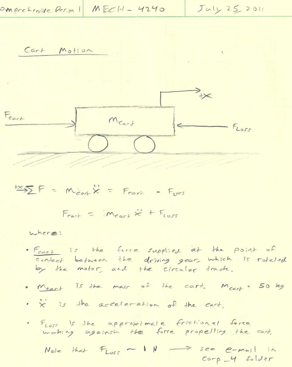
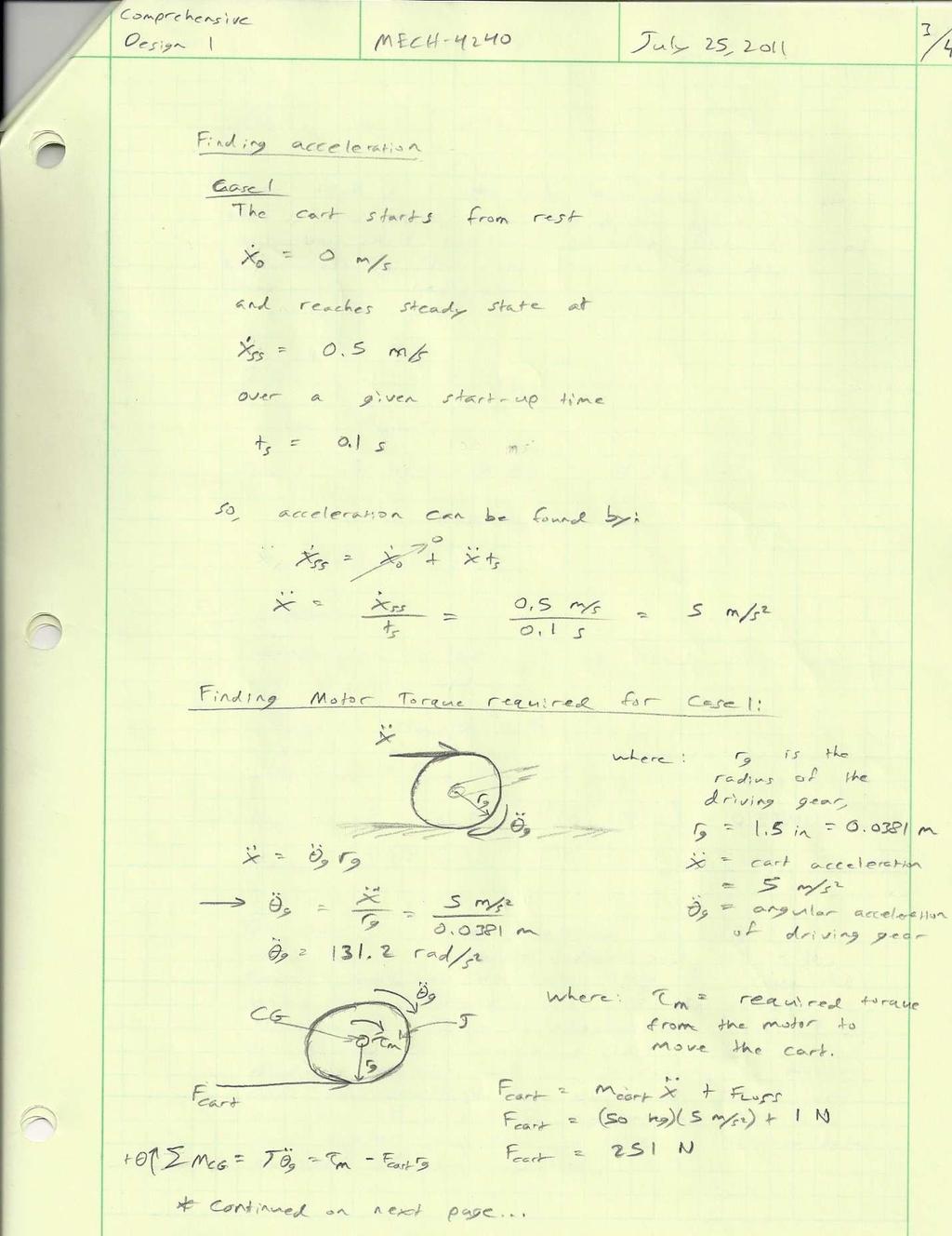
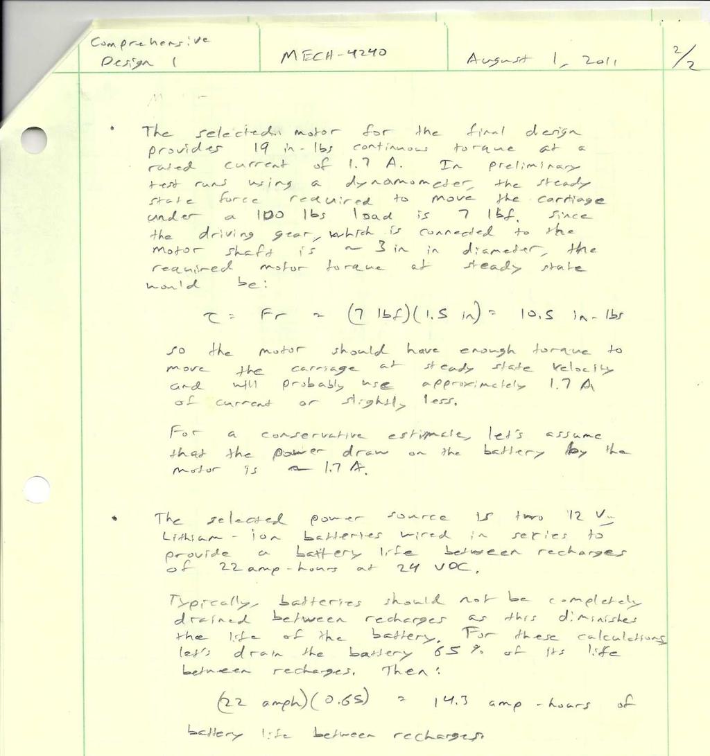
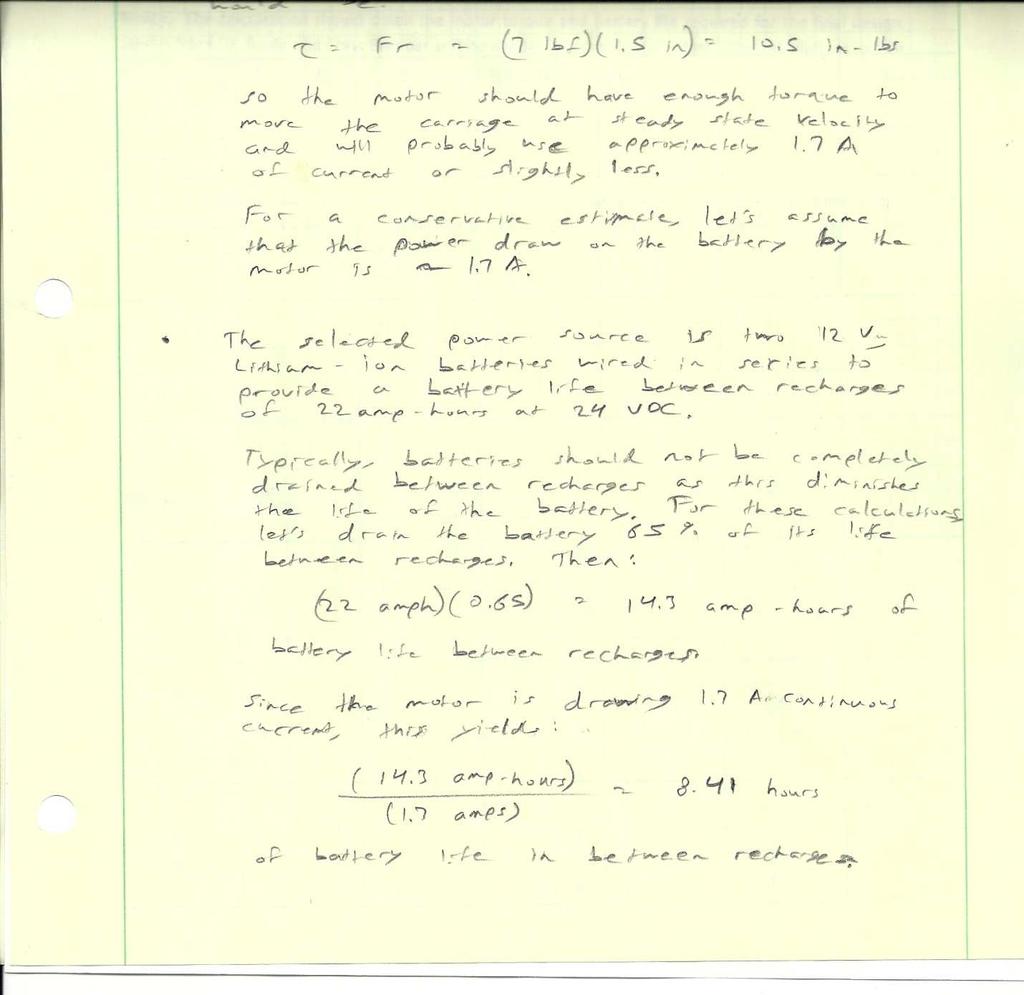
21 INTERFACES AND ICD: While there are few system boundaries at this point, there are several electrical and mechanical boundaries worth noting. The selected caster wheels have a load limit of 90 lbs. Since there are four caster wheels supporting the entire weight of the carriage, maximum weight limit of the chassis, the platform, the electrical components, and all other parts can be estimated at 360 lbs. This mechanical limit does not present a problem for carriage design because the target weight of the carriage and all components is approximately 50 lbs- the lighter the carriage, the longer the battery life in between recharges. There are also two important electrical boundaries at this point in the design. First, the motor runs on 24 VDC and is rated for 1.7 Amps. If the motor draws too much or too little current, it must be resized for optimal efficiency. Also, the selected motor controller can accommodate motors that run on a DC voltage in between 5.5 Volts and 40 Volts and the motor controller can supply up to 7 Amps continuous current. The current motor and motor controller combination would work well together, but if either the motor or controller must be changed for any reason, these electrical limits must be kept in mind. There will be thermal boundaries for the carriage and more importantly, for the electronics, but since all the electronics have not been selected at this time, the thermal limitations for the system are- yet to be decided. MISSION ENVIRONMENT: Environmental concerns for this project include overcoming the heat of the Deep South and moisture from the Gulf of Mexico that will adversely affect the test equipment. Efforts to overcome these effects include the addition of fans and other ventilation equipment for the purpose of keeping the electronics cool. The carriage will also require insulation at certain points on the automated carriage so that the users will be able to install or remove the carriage without burning their fingers and metal parts that have been exposed to the heat for long periods of time. Other environmental considerations include storms and severe weather, rain and high winds. For this reason, the electronics and even the carriage itself must be easily removed from the track and transported indoors. TECHNICAL BUDGET AND RESOURCE TRACKING The primary technical resource that needs to be budgeted for this design is battery power. When driving a motor that is correctly sized and draws approximately 1.7 amps of current at the steady state rpm, the estimated battery life of the chosen set of batteries is ~8 hours. In reality, the battery life will not last quite that long because it will be powering the cooling fans, the single board computer and other necessary electronics, but 8 hours is a reasonable first approximation for the life of the selected battery in between recharges. The calculations for estimating the battery life as well as calculations that discuss sizing an appropriate motor can be found in the appendix. 21
22 RISK MANAGEMENT: For the automated receiver, safety can easily be overlooked. The motor that drives the platform could possibly fail and one way to overcome this failure is to add a clutch mechanism to the gearing. In addition to safety, performance and longevity of the carriage must be considered. The carriage cannot be made so rugged that its weight would prohibit proper use, which could in turn lead to failure due to user error. Materials used must be considered for their ability to weather adverse conditions outdoors as well. Note that the track and gear rack will be assembled in sections so that if one section fails for any reason, it can easily be replaced with similar parts. Now that the final concept has been decided, prototypes, scale models, and material samples are available; Failure Analysis and Destructive Testing will be done. SUBSYSTEMS DESIGN ENGINEERING: The first subsystem includes the motor with optical encoder and battery which was chosen based on many hand calculations including the torque, velocity, weight of the entire carriage, and acceleration. The motor was chosen based on the rated continuous current of 1.7 amperes and the rated continuous torque of 19 inch pounds. The optical encoder was an option for the motor chosen and was needed for the positioning system. The batteries were chosen based on the voltage supplied and the durability and longevity of lithium ion batteries. The batteries run in series will supply 24 volts to the motor and will last from six to eight hours of constant operation. Shown below is a diagram of the motor and encoder to be used in the design. 22

23 Figure 12 Midwest Motion Motor (Top) and Encoder (Bottom) The second subsystem consist of the entire mechanical drive system which moves the carriage forwards and reverse along with the position. A gear will be placed on the shaft of the motor and it will align with the gear rack that will be placed on top of the track via a few strategically located welds. The gear rack and gear was chosen for better control of the carriage along with having a precise positioning system at all times since there will a reading taken every one degree. The gear and gear rack will allow for very low maintenance, installation, and durability over many runs. A photo is shown below on how the gear will come in contact with the gear rack. Figure 13 Gear and Gear Rack The chassis utilizes a lightweight slotted frame that has much versatility along with great strength. The slotted frame has been used many times in the Neptune Technologies plant over the years and has earned a very good reputation for durability, strength, and versatility. The casters used are very inexpensive as well as having more than enough strength to be able to support the 100 pound load with ease. The main casters used are all swivel casters rated at 90 pounds each. Swivel casters were used because of the slight curve the track has as well as being able to not bind up as much if the direction of the cart were reversed. The side casters are fixed casters which will guide the carriage around the track since the casters will be rolling vertically. The casters that will be used on the carriage are shown below. The platform used will be made of an aluminum plate of thickness. The aluminum plate was used for the corrosion resistance to the environment as well as having just as much strength as steel but weighing. 23


24 Figure 14 Swivel and Rigid Casters The platform will carry the motor, electronics, and mast. The platform will have a section under the motor where the platform will be raised and lowered to disengage and engage the motor gear to the gear rack acting as a clutch system. The electronics will be incased in a tower that will have multiple fans to help cool the electronics under a load and high temperatures. The mast will have two parts associated with it. The first part will be the steel pipe that will be welded to a plate that will be bolted to the platform. The second part of the mast will be the PVC pipe that will slide down over the steel pipe and be held in place via nuts and bolts. The figure below shows how small the battery will be that is used in this design. Figure Volt Battery Pack 24

25 The last subsystem is the data acquisition system that controls the motor and electronics. This system will consist of a motherboard that will control everything on the cart from the velocity to the thermostat controlled fans. The motherboard will be supplied with power from the two lithium ion batteries on board incased in the tower and will communicate with the wireless system that will relay all of the information gathered from the receiver to the base station. The user will be able to evaluate the signal at the precise position and record all of the information gathered and to be analyzed. Figure 16 Motor Controller 24V (Fully Assembled) 25


26 Neptune Technologies will be providing several parts to the data acquisition system including the test antenna, test water meter, mobile receiver as well as the single board computer. The reason the company is supplying all of the parts because they presently use them in the company s testing procedures. The receiver to be used in this design is shown below. Project Management: Figure 17 Signal Hound Receiver Critical Design Review Division of Tasks In order to operate efficiently as a group, the project was divided up into tasks to which teams were assigned. These teams included Carriage and Wheels, Motor and Clutch, Gear and Rack, Motor/Electronics cooling. These teams focus on their tasks and when needed corresponded with other teams to insure a cohesive design. This system of operation allowed the group to work on multiple tasks at one time but still have the design come together without conflict. Table 3 - Teams and Tasks 26
27 This coordinated effort kept us on schedule with the Design Project Schedule formed at the beginning of the semester. As forecasted in the schedule, we generated the working concepts by June 26 and had moved into the embodiment of final design by July 23. On July 8, Corp 4 presented the different feasible designs and the design that was chosen for further development. All along Neptune has been consulted and informed of any changes to the design. Proposed Second Semester Deliverables Corp 4 s focus at the beginning of next semester is to complete the prototyping process by testing a gear, rack, motor, and battery assembly. This will allow for the best design to be chosen and further development to continue. Next is to work with the Neptune sponsors to purchase the single board computer and wireless transmitter. Once the electronics are purchased a layout plan will be generated that maximizes the operating efficiency of each unit, regarding heat, UV, and precipitation exposure. The electronics must operate within a specific temperature to avoid damage. This will be maintained by an electric fan cooling system, designed for optimal results, which runs off the onboard battery. Also, to ensure consistent operating performance from the cart, Neptune will be consulted about coding the motor controls in Labview. CONCLUSION: In conclusion, the final design meets all of Neptune s requirements. It is easy to assemble and requires low maintenance. Also it has been designed to allow for future modifications and/or upgrades in the following years. This automated data collection system will improve Neptune s overall accuracy of test results and dramatically decrease the time it takes to collect data from the test antenna. Neptune will continue to be informed of new developments in the design and components of the design. Corp 4 is currently transitioning from detail design into prototyping and will begin the manufacturing process early in the Fall 2011 semester. 27
28 APPENDIX: 1. DESIGN TEAM S SCHEDULE Table 4 Design Schedule Project Task Define Problem Statement Identify Users, Needs, Values Conduct Research, Dom. Knowledge I.D. Engineering Requirements Refine Problem Statement Create Functional Decomposition Generate Working Concepts Assess Working Concepts Embodiment of Final Design Develop Manufacturing Plan Order/ Ship/ Manufacturing Plan Assemble Working Prototype Test and Make Revisions Time Required for Task Start Date End Date Day 1 June 5, 2011 June 6, 2011 Day 1 June 5, 2011 June 6, 2011 Week 1 June 5, 2011 June 12, 2011 Week 2 June 12, 2011 June 19, 2011 Week 2 June 12, 2011 June 19, 2011 Week 2 June 12, 2011 June 19, 2011 Week 3 June 19, 2011 June 26, 2011 Week 4, Week 5 June 26, 2011 July 9, 2011 Week 6, Week 7 July 10, 2011 July 23, 2011 Week 8 July 24, 2011 July 31, 2011 Week 9, Week 10, Week 11, Week 12 Week 13, Week 14, Week 15 Week 16, Week 17, Week 18, Week 19 July 31, 2011 August 27, 2011 August 28, 2011 September 18, 2011 September 17, 2011 October 15,

29 2. PRELIMINARY MOTOR TORQUE CALCULATIONS 29
30 粰 Ҏ 30
31 31

32 陰 Ң 32

33 3. PRELIMINARY POWER AND BATTERY LIFE CALCULATIONS 33
34 34

35 4. COMPONENT SPECIFICATION SHEETS DEBEN 12 VOLT LITHIUM ION BATTERY SPECIFICATIONS 粰 Ҏ 35

36 MIDWEST MOTOR SPECIFICATIONS 粰 Ҏ 36

37 MIDWEST MOTION ENCODER SPECIFICATIONS 粰 Ҏ 37

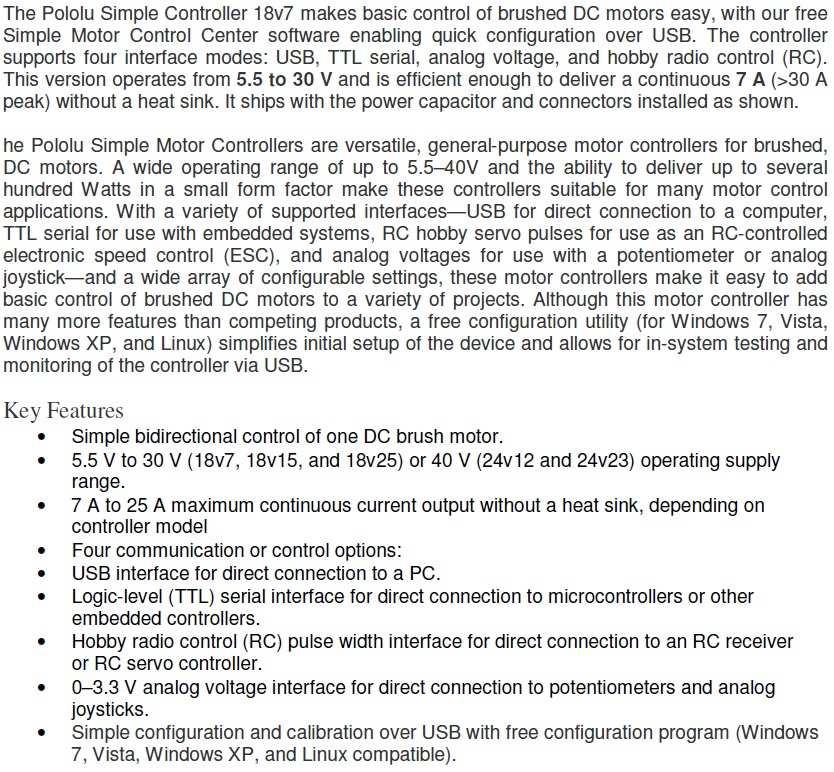
38 POLOLU MOTOR CONTROLLER ѳ 38
39 巰 39
CORP 4 PROJECT GROUP BENJAMIN BETHEL GRAYSON DAWSON CODY OWEN KYLE PALMER DANIEL PAULK
 NEPTUNE TECHNOLOGY GROUP AUTOMATED DATA COLLECTION FOR ANTENNAS MECH 4240 CONCEPTS REVIEW SUMMER 2011 JULY 8, 2011 DR. BEALE AUBURN UNIVERSITY MECHANICAL ENGINEERING CORP 4 PROJECT GROUP BENJAMIN BETHEL
How to: Test & Evaluate Motors in Your Application
 How to: Test & Evaluate Motors in Your Application Table of Contents 1 INTRODUCTION... 1 2 UNDERSTANDING THE APPLICATION INPUT... 1 2.1 Input Power... 2 2.2 Load & Speed... 3 2.2.1 Starting Torque... 3
Introduction: Problem statement
 Introduction: Problem statement The goal of this project is to develop a catapult system that can be used to throw a squash ball the farthest distance and to be able to have some degree of accuracy with
Orbital Test Stand. By Mary Begay, Brett Booen, Calvin Boothe, James Ellis and Nicholas Garcia. Team 7. Project Proposal Document
 Orbital Test Stand By Mary Begay, Brett Booen, Calvin Boothe, James Ellis and Nicholas Garcia Team 7 Project Proposal Document Submitted towards partial fulfillment of the requirements for Mechanical Engineering
Lightweight, Collapsible Wind Turbine
 Lightweight, Collapsible Wind Turbine Design Team Dan Faulkner, Leanne Fortune, Alex Schaps, Kevin Zephir Design Advisor Prof. Mohammad Taslim Abstract The goal of this project is to create a more cost
Detailed Design Review
 Detailed Design Review P16241 AUTONOMOUS PEOPLE MOVER PHASE III Team 2 Agenda Problem Definition Review Background Problem Statement Project Scope Customer Requirements Engineering Requirements Detailed
SAE Mini BAJA: Suspension and Steering
 SAE Mini BAJA: Suspension and Steering By Zane Cross, Kyle Egan, Nick Garry, Trevor Hochhaus Team 11 Progress Report Submitted towards partial fulfillment of the requirements for Mechanical Engineering
Stationary Bike Generator System
 Central Washington University ScholarWorks@CWU All Undergraduate Projects Undergraduate Student Projects Spring 2017 Stationary Bike Generator System Rakan Alghamdi Central Washington University, rk_rk11@hotmail.com
Progress Report. Maseeh College of Engineering & Computer Science Winter Kart 2. Design Team Atom Falcone Austin Greene. Nick Vanklompenberg
 Progress Report Maseeh College of Engineering & Computer Science Winter 2016 Kart 2 Design Team Atom Falcone Austin Greene Jesse Majoros Nick Vanklompenberg Jake Waterman Jeffrey Williamson Faculty Advisor
SAE Baja - Drivetrain
 SAE Baja - Drivetrain By Ricardo Inzunza, Brandon Janca, Ryan Worden Team 11 Engineering Analysis Document Submitted towards partial fulfillment of the requirements for Mechanical Engineering Design I
Centerwide System Level Procedure
 5.ARC.0004.2 1 of 10 REVISION HISTORY REV Description of Change Author Effective Date 0 Initial Release J. Hanratty 7/17/98 1 Clarifications based on 7/98 DNV Audit and 6/98 Internal Audit (see DCR 98-029).
Smart Automated Vent Register Using an SMA Spring Actuated Rotary Ratchet
 Smart Automated Vent Register Using an SMA Spring Actuated Rotary Ratchet Mary Molepske, Victor Braciszewski, James Butler, Gregory Caputo, Fan-Ning Cheng, WonHee Kim, Jonathan Luntz, Diann Brei ABSTRACT
Electromagnetic Fully Flexible Valve Actuator
 Electromagnetic Fully Flexible Valve Actuator A traditional cam drive train, shown in Figure 1, acts on the valve stems to open and close the valves. As the crankshaft drives the camshaft through gears
RED RAVEN, THE LINKED-BOGIE PROTOTYPE. Ara Mekhtarian, Joseph Horvath, C.T. Lin. Department of Mechanical Engineering,
 RED RAVEN, THE LINKED-BOGIE PROTOTYPE Ara Mekhtarian, Joseph Horvath, C.T. Lin Department of Mechanical Engineering, California State University, Northridge California, USA Abstract RedRAVEN is a pioneered
9 Locomotive Compensation
 Part 3 Section 9 Locomotive Compensation August 2008 9 Locomotive Compensation Introduction Traditionally, model locomotives have been built with a rigid chassis. Some builders looking for more realism
Stationary Bike Generator System (Drive Train)
") Central Washington University ScholarWorks@CWU All Undergraduate Projects Undergraduate Student Projects Summer 2017 Stationary Bike Generator System (Drive Train) Abdullah Adel Alsuhaim cwu, 280zxf150@gmail.com
Central Washington University ScholarWorks@CWU All Undergraduate Projects Undergraduate Student Projects Summer 2017 Stationary Bike Generator System (Drive Train) Abdullah Adel Alsuhaim cwu, 280zxf150@gmail.com
Harnessing Wind Energy with Recyclable Materials By Katherine Carroll, Margo Dufek, Leanne Willey, and Andrew McCarthy Team 03
 Harnessing Wind Energy with Recyclable Materials By Katherine Carroll, Margo Dufek, Leanne Willey, and Andrew McCarthy Team 03 Midpoint Review Document Submitted towards partial fulfillment of the requirements
INTRODUCTION Team Composition Electrical System
 IGVC2015-WOBBLER DESIGN OF AN AUTONOMOUS GROUND VEHICLE BY THE UNIVERSITY OF WEST FLORIDA UNMANNED SYSTEMS LAB FOR THE 2015 INTELLIGENT GROUND VEHICLE COMPETITION University of West Florida Department
PRELIMINARY DESIGN REVIEW
 PRELIMINARY DESIGN REVIEW AUBURN UNIVERSITY NASA LUNABOT TEAM MARCH 28, 2014 MATTHEW JONES DAVID FAUCETT STEWARD BOYD WILL FLOURNOY TECHNICAL ADVISOR/OVERLORD - DR. BEALE SPONSORS-DR. MADSEN, DR. WILLIAMS,
M:2:I Milestone 2 Final Installation and Ground Test
 Iowa State University AerE 294X/AerE 494X Make to Innovate M:2:I Milestone 2 Final Installation and Ground Test Author(s): Angie Burke Christopher McGrory Mitchell Skatter Kathryn Spierings Ryan Story
An Automated System for the Acoustical and Aerodynamic Characterization of Small Air Moving Devices
 Minneapolis, Minnesota NOISE-CON 2005 2005 October 17-19 An Automated System for the Acoustical and Aerodynamic Characterization of Small Air Moving Devices Jeff G. Schmitt David A. Nelson John Phillips
Engineering Design Process for BEST Robotics JANNE ACKERMAN COLLIN COUNTY (COCO) BEST & BEST OF TEXAS ROBOTICS
 BEST & BEST OF TEXAS ROBOTICS") Engineering Design Process for BEST Robotics JANNE ACKERMAN COLLIN COUNTY (COCO) BEST & BEST OF TEXAS ROBOTICS Agenda Getting Started Lessons Learned Design Process Engineering Mechanics 2 Save Time Complete
Engineering Design Process for BEST Robotics JANNE ACKERMAN COLLIN COUNTY (COCO) BEST & BEST OF TEXAS ROBOTICS Agenda Getting Started Lessons Learned Design Process Engineering Mechanics 2 Save Time Complete
Beyond Standard. Dynamic Wheel Endurance Tester. Caster Concepts, Inc. Introduction: General Capabilities: Written By: Dr.
 Dynamic Wheel Endurance Tester Caster Concepts, Inc. Written By: Dr. Elmer Lee Introduction: This paper details the functionality and specifications of the Dynamic Wheel Endurance Tester (DWET) developed
F.I.R.S.T. Robotic Drive Base
 F.I.R.S.T. Robotic Drive Base Design Team Shane Lentini, Jose Orozco, Henry Sick, Rich Phelan Design Advisor Prof. Sinan Muftu Abstract F.I.R.S.T. is an organization dedicated to inspiring and teaching
Folding Shopping Cart Design Report
 Folding Shopping Cart Design Report EDSGN 100 Section 010, Team #4 Submission Date- 10/28/2013 Group Image with Prototype Submitted by: Arafat Hossain, Mack Burgess, Jake Covell, and Connor Pechko (in
Mobile Computer Cart
 Mobile Computer Cart By: Mohammed Aldosari, Abdulrahman Alhamdi, Joel Asirsan, Samuel Martin, and Trevor Scott Team 12 Engineering Analysis Submitted towards partial fulfillment of the requirements for
The Deployable Gage Restraint Measurement System - Description and Operational Performance
 The Deployable Gage Restraint Measurement System - Description and Operational Performance GARY A. MARTIN ENSCO, INC 5400 PORT ROYAL ROAD SPRINGFIELD, VA 22151 703-321-4513 703-321-7619 (FAX) JEFFREY A.
Lockheed Martin. Team IDK Seung Soo Lee Ray Hernandez Chunyu PengHarshal Agarkar
 Lockheed Martin Team IDK Seung Soo Lee Ray Hernandez Chunyu PengHarshal Agarkar Abstract Lockheed Martin has developed several different kinds of unmanned aerial vehicles that undergo harsh forces when
Remote Control Helicopter. Engineering Analysis Document
 Remote Control Helicopter By Abdul Aldulaimi, Travis Cole, David Cosio, Matt Finch, Jacob Ruechel, Randy Van Dusen Team 04 Engineering Analysis Document Submitted towards partial fulfillment of the requirements
SP5 INSTALLATION AND SETUP MANUAL
 SP5 INSTALLATION AND SETUP MANUAL 1 Installation 1.1 Introduction The SP5 System consists of a Data Acquisition unit (DAQ) with two complete Roller control channels, each Roller Control Channel consists
SAE Baja - Drivetrain
 SAE Baja - Drivetrain By Ricardo Inzunza, Brandon Janca, Ryan Worden Team 11A Concept Generation and Selection Document Submitted towards partial fulfillment of the requirements for Mechanical Engineering
Cam Motion Case Studies #1 and # 2
 Cam Motion Case Studies #1 and # 2 Problem/Opprtunity: At an operating speed of 150 to 160 rpm, Cam Motion #1 causes the cam follower to leave the cam surface unless excessive air pressure is applied to
Reciprocating Compressor Installation and Validation
 Reciprocating Compressor Installation and Validation MSD II - 11452 John Blamer (ME) Team Leader Promit Bagchi (ME) Lead Engineer Elliot Kendall (ME) Hydronics Engineer Matthias Purvis (ME) Operations
Electrical Systems. Introduction
 Electrical Systems Figure 1. Major Components of the Car s Electrical System Introduction Electricity is used in nearly all systems of the automobile (Figure 1). It is much easier to understand what electricity
High Level Design ElecTrek
 High Level Design ElecTrek EE Senior Design November 9, 2010 Katie Heinzen Kathryn Lentini Neal Venditto Nicole Wehner Table of Contents 1 Introduction...3 2 Problem Statement and Proposed Solution...3
TRANSLATION (OR LINEAR)
") 5) Load Bearing Mechanisms Load bearing mechanisms are the structural backbone of any linear / rotary motion system, and are a critical consideration. This section will introduce most of the more common
5) Load Bearing Mechanisms Load bearing mechanisms are the structural backbone of any linear / rotary motion system, and are a critical consideration. This section will introduce most of the more common
Linear Shaft Motors in Parallel Applications
 Linear Shaft Motors in Parallel Applications Nippon Pulse s Linear Shaft Motor (LSM) has been successfully used in parallel motor applications. Parallel applications are ones in which there are two or
How to Achieve a Successful Molded Gear Transmission
 How to Achieve a Successful Molded Gear Transmission Rod Kleiss Figure 1 A molding insert tool alongside the molded gear and the gear cavitiy. Molded plastic gears have very little in common with machined
FOLDING SHOPPING CART
 1 EDSGN 100: Introduction to Engineering Design Section 10 Team 6 FOLDING SHOPPING CART Submitted by: Kevin Chacha, Ugonna Onyeukwu, Patrick Thornton, Brian Hughes Submitted to: Xinli Wu October 28, 2013
Foldable Shopping Cart Project
 http://www.personal.psu.edu/mmf206/edsgn100_fa16_section07_team6_dpl.pdf EDSGN 100: Introduction to Engineering Design Foldable Shopping Cart Project Section 07 Team # 6 Submitted by: Ghadah Alamer, Joseph
Enhancing Wheelchair Mobility Through Dynamics Mimicking
 Proceedings of the 3 rd International Conference Mechanical engineering and Mechatronics Prague, Czech Republic, August 14-15, 2014 Paper No. 65 Enhancing Wheelchair Mobility Through Dynamics Mimicking
HIGH VOLTAGE vs. LOW VOLTAGE: POTENTIAL IN MILITARY SYSTEMS
 2013 NDIA GROUND VEHICLE SYSTEMS ENGINEERING AND TECHNOLOGY SYMPOSIUM POWER AND MOBILITY (P&M) MINI-SYMPOSIUM AUGUST 21-22, 2013 TROY, MICHIGAN HIGH VOLTAGE vs. LOW VOLTAGE: POTENTIAL IN MILITARY SYSTEMS
Solar Boat Capstone Group
 Solar Boat Capstone Group Design Team Chris Maccia, Jeff Tyler, Matt Knight, Carla Pettit, Dan Sheridan Design Advisor Prof. M. Taslim Abstract Every year Solar Splash, the IEEE World Championship of intercollegiate
OBJECTIVE: Design a unique lighting device with your team using ONLY McMaster-Carr parts
 DESIGNING & BUILDING PROTOTYPES WITH SOURCED PARTS Instructor: Eric Sugalski Email: sugalski@mit.edu OBJECTIVE: Design a unique lighting device with your team using ONLY McMaster-Carr parts RULES: - Must
Low and medium voltage service. Power Care Customer Support Agreements
 Low and medium voltage service Power Care Customer Support Agreements Power Care Power Care is the best, most convenient and guaranteed way of ensuring electrification system availability and reliability.
Slippage Detection and Traction Control System
 Slippage Detection and Traction Control System May 10, 2004 Sponsors Dr. Edwin Odom U of I Mechanical Engineering Department Advisors Dr. Jim Frenzel Dr. Richard Wall Team Members Nick Carter Kellee Korpi
GNEG 1103 Introduction to Engineering FALL Team Design Project. Portable Phone Charger. Project Presentation. December 2, 2013, 8:00-9:15 A.
 1 GNEG 1103 Introduction to Engineering FALL 2013 Team Design Project Portable Phone Charger Project Presentation December 2, 2013, 8:00-9:15 A.M Derek Richard, Jarod Brunick, Luis Ramirez, Mason Torgerson
REMOTE SENSING DEVICE HIGH EMITTER IDENTIFICATION WITH CONFIRMATORY ROADSIDE INSPECTION
 Final Report 2001-06 August 30, 2001 REMOTE SENSING DEVICE HIGH EMITTER IDENTIFICATION WITH CONFIRMATORY ROADSIDE INSPECTION Bureau of Automotive Repair Engineering and Research Branch INTRODUCTION Several
Battery Technology for Data Centers and Network Rooms: Site Planning
 Battery Technology for Data Centers and Network Rooms: Site Planning White Paper # 33 Executive Summary The site requirements and costs for protecting information technology and network environments are
2018 KANSAS BEST BREAKOUT SESSIONS
 2018 KANSAS BEST BREAKOUT SESSIONS Tips for Building a Robot Bryan Jaax September 8, 2018 1 ST STEP: READ the RULES and Technical Data Package 2 FOLLOW AN ENGINEERING PROCESS Define the Problem Brainstorm:
Cornell University Autonomous Underwater Vehicle Team Spring Frame
 Cornell University Autonomous Underwater Vehicle Team Spring 2014 Frame Technical Report Kent Esslinger (kde26) May 21, 2014 Contents 1 Abstract 2 2 Design Requirements 2 3 Previous Designs 3 3.1 Drekar...............................
EEL Project Design Report: Automated Rev Matcher. January 28 th, 2008
 Brad Atherton, masscles@ufl.edu, 352.262.7006 Monique Mennis, moniki@ufl.edu, 305.215.2330 EEL 4914 Project Design Report: Automated Rev Matcher January 28 th, 2008 Project Abstract Our device will minimize
Primer. Stepper Motors
 Primer Stepper Motors Phidgets - Primer Manual Motors Phidgets Inc. 2011 Contents 4 Introduction 5 Types of Stepper Motors 7 Controlling the Stepper Motor 9 Selecting a Gearbox 10 Glossary of Terms Introduction
Self-Adjusting Clutch (SAC) Technology Special tools / User instructions
 Technology Special tools / User instructions") Self-Adjusting Clutch (SAC) Technology Special tools / User instructions The content of this brochure shall not be legally binding and is for information purposes only. To the extent legally permissible,
Self-Adjusting Clutch (SAC) Technology Special tools / User instructions The content of this brochure shall not be legally binding and is for information purposes only. To the extent legally permissible,
Is Low Friction Efficient?
 Is Low Friction Efficient? Assessment of Bearing Concepts During the Design Phase Dipl.-Wirtsch.-Ing. Mark Dudziak; Schaeffler Trading (Shanghai) Co. Ltd., Shanghai, China Dipl.-Ing. (TH) Andreas Krome,
Mars Surface Mobility Proposal
 Mars Surface Mobility Proposal Jeremy Chavez Ryan Green William Mullins Rachel Rodriguez ME 4370 Design I October 29, 2001 Background and Problem Statement In the 1960s, the United States was consumed
7956 Series MatTop Chains Design Manual Series MatTop Chains
 7956 Series MatTop Chains Design Manual 7956 Series MatTop Chains 1 Contents Safety Considerations/Introduction...2-3 Chain Selection - Selection Criteria...4 - Specifying and Part Number Nomenclature...5
Servo Creel Development
 Servo Creel Development Owen Lu Electroimpact Inc. owenl@electroimpact.com Abstract This document summarizes the overall process of developing the servo tension control system (STCS) on the new generation
2012 Baja SAE Drivetrain
 2012 Baja SAE Drivetrain A thesis submitted to the Faculty of the Mechanical Engineering Technology Program of the University of Cincinnati in partial fulfillment of the requirements for the degree of
Executive Summary: Design of a Small Scale Wind Turbine to Improve Drinking Water in Garacad, Somalia
 Executive Summary: Design of a Small Scale Wind Turbine to Improve Drinking Water in Garacad, Somalia Khalifa Alsuwaidi, Austin Kiker, and Robert Napoli Team 6.4, ME 340, Mechanical Engineering Department,
ME 455 Lecture Ideas, Fall 2010
 ME 455 Lecture Ideas, Fall 2010 COURSE INTRODUCTION Course goal, design a vehicle (SAE Baja and Formula) Half lecture half project work Group and individual work, integrated Design - optimal solution subject
Introduction to Engineering Design 100. Foldable Shopping Cart
 1 Introduction to Engineering Design 100 Section 10 Team 7 Foldable Shopping Cart Submitted by: Nick Vuotto, Quoc Tran, Pete White, Mark Cecco (from left to right) Submitted to: Xinli Wu Spring 2014 2
SP4 DOCUMENTATION. 1. SP4 Reference manual SP4 console.
 SP4 DOCUMENTATION 1. SP4 Reference manual.... 1 1.1. SP4 console... 1 1.2 Configuration... 3 1.3 SP4 I/O module.... 6 2. Dynamometer Installation... 7 2.1. Installation parts.... 8 2.2. Connectors and
Project Report Cover Page
 New York State Pollution Prevention Institute R&D Program 2015-2016 Student Competition Project Report Cover Page University/College Name Team Name Team Member Names SUNY Buffalo UB-Engineers for a Sustainable
Robotic Device for Cleaning of Photovoltaic Arrays V2
 Robotic Device for Cleaning of Photovoltaic Arrays V2 Design Team Greg Belogolovsky, Steve Bennett, Istvan Hauer, Salome Morales, Leonid Nemiro Design Advisor Constantinos Mavroidis, Ph.D. Richard Ranky,
Transmission Error in Screw Compressor Rotors
 Purdue University Purdue e-pubs International Compressor Engineering Conference School of Mechanical Engineering 2008 Transmission Error in Screw Compressor Rotors Jack Sauls Trane Follow this and additional
QuickStick Repeatability Analysis
 QuickStick Repeatability Analysis Purpose This application note presents the variables that can affect the repeatability of positioning using a QuickStick system. Introduction Repeatability and accuracy
Theory of Machines II EngM323 Laboratory User's manual Version I
 Theory of Machines II EngM323 Laboratory User's manual Version I Table of Contents Experiment /Test No.(1)... 2 Experiment /Test No.(2)... 6 Experiment /Test No.(3)... 12 EngM323 Theory of Machines II
System Integration of an Electronic Monitoring System in All-Terrain Vehicles
 System Integration of an Electronic Monitoring System in All-Terrain Vehicles Waylin Wing Central Michigan University, Mount Pleasant, MI 48858 Email: wing1wj@cmich.edu An electronic monitoring system
Understanding the benefits of using a digital valve controller. Mark Buzzell Business Manager, Metso Flow Control
 Understanding the benefits of using a digital valve controller Mark Buzzell Business Manager, Metso Flow Control Evolution of Valve Positioners Digital (Next Generation) Digital (First Generation) Analog
Use of Flow Network Modeling for the Design of an Intricate Cooling Manifold
 Use of Flow Network Modeling for the Design of an Intricate Cooling Manifold Neeta Verma Teradyne, Inc. 880 Fox Lane San Jose, CA 94086 neeta.verma@teradyne.com ABSTRACT The automatic test equipment designed
SAE Mini BAJA: Suspension and Steering
 SAE Mini BAJA: Suspension and Steering By Zane Cross, Kyle Egan, Nick Garry, Trevor Hochhaus Team 11 Project Progress Submitted towards partial fulfillment of the requirements for Mechanical Engineering
Initial Project and Group Identification Document. Metal detecting robotic vehicle (seek and find metallic objects using a robotic vehicle)
") Initial Project and Group Identification Document Project Idea: Metal detecting robotic vehicle (seek and find metallic objects using a robotic vehicle) Team Members: Robertson Augustine (Computer Engineer)
Initial Project and Group Identification Document Project Idea: Metal detecting robotic vehicle (seek and find metallic objects using a robotic vehicle) Team Members: Robertson Augustine (Computer Engineer)
Foldable Shopping Cart EDSGN 100 Section 202 Team 3
 Foldable Shopping Cart EDSGN 100 Section 202 Team 3 http://personal.psu.edu/jnb5392/homepage.htm Submitted by: Alex Thomason Christian Sak Jeremy Deppen Jerod Barone Submitted to: Xinli Wu 30 July 2015
Linear Actuators for On/Off-Highway Vehicles
 Linear Actuators for On/Off-Highway Vehicles Thomson Actuators Set the Standard in On-Off Highway Vehicles We are the original actuator manufacturer. For over 40 years, our engineers have worked to design
e-nable Hand Test Rig
 enable Hand Test Rig P606 David chwartz, Tia Parks, hannon Barry, amantha Mason, Charles Rumfola Agenda Recap Problem tatement Customer Requirements Engineering Requirements ubsystems Clamp election Controller/Processor
Fall Presentation December 1, 2015
 Fall Presentation December 1, 2015 Gage Martin Kade Coulter Jodi Vinyard Shelby Weber Barrett Trailers was conceived in Oklahoma City in 1973. Since then the company has grown and relocated into a 75,000
Development of a Multibody Systems Model for Investigation of the Effects of Hybrid Electric Vehicle Powertrains on Vehicle Dynamics.
 Development of a Multibody Systems Model for Investigation of the Effects of Hybrid Electric Vehicle Powertrains on Vehicle Dynamics. http://dx.doi.org/10.3991/ijoe.v11i6.5033 Matthew Bastin* and R Peter
City of Storm Lake Fire Department Heavy Rescue Specifications
 INTENT OF SPECIFICATIONS City of Storm Lake Fire Department Heavy Rescue Specifications It shall be the intent of these specifications to provide a complete apparatus equipped as hereinafter specified.
Introducing NJK Precision Airflow Measuring Stations
 Introducing Precision Airflow Measuring Stations A new and unique airflow measuring station that accurately measures airflows at very low flow rates and can operate in physically restrictive applications
2012 Dalhousie University Formula SAE Design Report
 Dalhousie University Car #47 - Formula SAE Michigan fsae@dal.ca Introduction 2012 Dalhousie University Formula SAE Design Report The 2012 Dalhousie University Formula SAE Team is competing in Formula SAE,
Solar Power-Optimized Cart
 Solar Power-Optimized Cart Initial Project and Group Identification Document Due: September 17, 2013 Group #28 Group Members: Jacob Bitterman Cameron Boozarjomehri William Ellett Potential Sponsors: Duke
DESIGN GUIDE Push-Pull and Pull-Pull Controls Design Guide. Push-Pull Controls. Pull-Pull Controls
 CMA Control Cables DESIGN GUIDE Push-Pull and Pull-Pull Controls Design Guide There are many common, everyday applications that use efficient and reliable CMA controls. These applications include automotive
Mechanical Power Transmission. September 16, 2008
 2008 TE Sessions Supported by Mechanical Power Transmission September 16, 2008 www.robojackets.org Goals Hand out kits to teams that don t have one. More physics concepts and terms Understanding key devices
Development of a Moving Automatic Flagger Assistance Device (AFAD) for Moving Work Zone Operations
 for Moving Work Zone Operations") Development of a Moving Automatic Flagger Assistance Device (AFAD) for Moving Work Zone Operations Edward F. Terhaar, Principal Investigator Wenck Associates, Inc. March 2017 Research Project Final Report
Development of a Moving Automatic Flagger Assistance Device (AFAD) for Moving Work Zone Operations Edward F. Terhaar, Principal Investigator Wenck Associates, Inc. March 2017 Research Project Final Report
A Travel Aid for the Blind. Introduction to engineering design GE105
 A Travel Aid for the Blind Introduction to engineering design GE105 Presented by Supervised by Presentation Planning Introduction. Definition the problem. Need analysis. Primary objectives. Secondary object.
EDSGN 100. Folding Shopping Cart
 EDSGN 100 Introduction to Engineering Design Section 0, Team #1 Folding Shopping Cart http://www.personal.psu.edu/jzb31/edsgn100_su16_section0_team1_dp1.pdf Submitted by: Jacob Barclay, Abhishek Ganta,
Linear Induction Motor (LIMO) Modular Test Bed for Various Applications
 Modular Test Bed for Various Applications") Linear Induction Motor (LIMO) Modular Test Bed for Various Applications ECE 4901 Senior Design I Fall 2013 Fall Project Report Team 190 Members: David Hackney Jonathan Rarey Julio Yela Faculty Advisor
Linear Induction Motor (LIMO) Modular Test Bed for Various Applications ECE 4901 Senior Design I Fall 2013 Fall Project Report Team 190 Members: David Hackney Jonathan Rarey Julio Yela Faculty Advisor
EDSGN 100: INTRODUCTION TO ENGINEERING DESIGN Section 204 Team #1 BOX CART
 EDSGN 100: INTRODUCTION TO ENGINEERING DESIGN Section 204 Team #1 BOX CART Submitted by: Chang - http://www.personal.psu.edu/cbl5289/ Vinay Murthy - http://www.personal.psu.edu/vum119/ Aidan Fitzpatrick
OHIO University Mechanical Engineering Concept Design Foot Powered Wheelchair Team B-Ballin
 OHIO University Mechanical Engineering Concept Design Foot Powered Wheelchair Team B-Ballin Andy Fay Evan Gilliland Sam Hallam Haowen Huo Trace Lydick Kyle Sullivan 11/11/2011 1.0 Concept Generation 1.1
SHORT-STOP. Electronic Motor Brake Type G. Instructions and Setup Manual
 Electronic Motor Brake Type G Instructions and Setup Manual Table of Contents Table of Contents Electronic Motor Brake Type G... 1 1. INTRODUCTION... 2 2. DESCRIPTION AND APPLICATIONS... 2 3. SAFETY NOTES...
University of New Hampshire: FSAE ECE Progress Report
 University of New Hampshire: FSAE ECE Progress Report Team Members: Christopher P. Loo & Joshua L. Moran Faculty Advisor: Francis C. Hludik, Jr., M.S. Courses Involved: ECE 541, ECE 543, ECE 562, ECE 633,
Projectile Impact Tester
 Projectile Impact Tester Design Team Neil Cameron, Laura Paradis, Tristan Whiting Betsy Huse, James Leithauser Design Advisor Prof. Mohammad Taslim Abstract The purpose of this project was to design a
M3 Design Product Teardown Kobalt Double-Drive Screwdriver
 19 Jun, 2013 Why do the product teardowns? M3 Design Product Teardown Kobalt Double-Drive Screwdriver Part of the product development process is to apply knowledge gained from prior experience during the
2019 SpaceX Hyperloop Pod Competition
 2019 SpaceX Hyperloop Pod Competition Rules and Requirements August 23, 2018 CONTENTS 1 Introduction... 2 2 General Information... 3 3 Schedule... 4 4 Intent to Compete... 4 5 Preliminary Design Briefing...
Spring Presentation April 28, 2016
 Spring Presentation April 28, 2016 Gage Martin Kade Coulter Jodi Vinyard Shelby Weber Barrett Trailers was conceived in Oklahoma City in 1973. Since then the company has grown and relocated into a 75,000
Overview of Air Bearings and Design Configurations Richard Pultar OPTI521 December 14, 2016
 Overview of Air Bearings and Design Configurations Richard Pultar OPTI521 December 14, 2016 Introduction Air bearings are a type of bearing that use pressurized air to create an air gap between two surfaces.
Working with VEX Parts
 VEX Robotics Design System VEX Classroom Lab Kit The VEX Robotics Design System is divided up into several different Subsystems: Structure Subsystem Motion Subsystem Power Subsystem Sensor Subsystem Logic
ASME Human Powered Vehicle
 ASME Human Powered Vehicle By Yousef Alanzi, Evan Bunce, Cody Chenoweth, Haley Flenner, Brent Ives, and Connor Newcomer Team 14 Problem Definition and Project Plan Document Submitted towards partial fulfillment
Rigid Base / Turntable Bed. Exploded side view of bottom rotating wood drive wheel, showing optics aligned to stop bracket.
 TURNTABLE INDEXER #617 for use with BOWSER and other, turntables by 246 W. Main St. Leola, PA 17540 (717) 661-7041 www.dallee.com OVERVIEW The TURNTABLE INDEXER unit has been made with simplicity of installation