2012 Product Catalog
|
|
|
- Richard Evans
- 6 years ago
- Views:
Transcription

1 2012 Product Catalog
2 Headquarters 1310 Rankin Rd. Houston, TX Copyright 2011 Schlumberger. All rights reserved. No part of this book may be reproduced, stored in a retrieval system, or transcribed in any form or by any means electronic or mechanical, including photocopying and recording without the prior written permission of the publisher. While the information presented herein is believed to be accurate, it is provided as is without express or implied warranty. Specifications are current at the time of printing. 11-BT-0027 An asterisk (*) is used throughout this document to denote a mark of Schlumberger. Other company, products and service names are the properties of their respective owners.

3 Table of Contents Technological Expertise 1 17 Innovative Smith Bits technology for every stage of drilling Fixed Cutter Bits A wide range of PDC and diamond-impregnated bits Roller Cone Bits A comprehensive selection for various applications Percussion Hammers and Bits Impax hammer products designed for oilfield applications Borehole Enlargement An extensive catalog of robust and reliable tools Reference Guide 73 93
4


5 Technological Expertise 1

 - DBOS* Drillbit Optimization System - YieldPoint RT* Drilling-Hydraulics")

6 Technological Expertise Innovative Smith Bits technology provides analyses, optimization, and support for every stage of the drilling program, from planning to execution Engineering and Modeling - IDEAS* Integrated Drillbit Design Platform - Computational Fluid Dynamics (CFD) Analysis - i-drill* Engineered Drilling System Design - Advanced Services Engineering (ASE) - DBOS* Drillbit Optimization System - YieldPoint RT* Drilling-Hydraulics and Hole-Cleaning Simulation Program - DRS* Drilling Record System PDC Technology - ONYX II* Premium PDC Cutters Roller Cone Technology - Hydraulics - Inserts Diamond-Impregnation Technology - Grit Hot-Pressed Inserts (GHIs) 2

7 Engineering and Modeling IDEAS Integrated Drillbit Design Platform Delivering application-specific drill bits with higher performance and greater reliability The IDEAS* platform uses advanced simulation and modeling to design and certify every new Smith Bits drill bit. It has five basic elements that enable it to optimize bit performance. Comprehensive drilling system analysis The design process takes into account the effects of the lithology at the rock-cutter interface, the drillstring, the drive system, individual BHA components, and the total system on bit behavior in a dynamic drilling environment. It also takes into account the specific operating parameters and the interaction between individual elements of the drilling assembly. Holistic design process Smith Bits design engineers account for every critical variable. Virtually every cone or cutter position is selected to create a stable bit that rotates around its center, a key requirement for efficient drilling. Application-specific enhancements Continuous improvement results in bits for a specific application that consistently outperform previous designs when measured against the same parameters, for example, ROP, durability, and specific bit behavior with a rotary steerable system. Drill bits that are certified by the IDEAS platform are dynamically stable within the operating envelope for which they are designed, leading to longer bit runs and less stress on the BHA. Each certified bit undergoes rigorous design evaluation and testing to produce a detailed application analysis of how it will perform for a specific drilling program. Rapid solutions with reliable results By using sophisticated modeling tools and by accounting for a multitude of dynamic variables in a virtual environment, the IDEAS platform moves bits through the design process much quicker, while ensuring better reliability and performance than ever before. The traditional trial-anderror approach is replaced by laboratory tests and simulations to quantify variables such as cutter forces and rock removal rates. Integration of advanced materials Stronger and more durable advanced cutter materials are used more effectively by working in conjunction with IDEAS design and simulation capabilities. The resulting bit has abrasion- and impactresistant cutters, and an optimal design for high performance. The IDEAS Platform Define Performance Objectives IDEAS Simulation Design Test Analyze Build Bit Test Bit Certify Bit Integrate new bit into product line IDEAS platform eliminates the costly and timeconsuming trial-and-error methods of the traditional drillbit design process, enabling Smith Bits to deliver a better solution faster. 3

8 Engineering and Modeling IDEAS Certification for Directional Applications Improving performance, reduces risk, and keeps directional wells and drilling budgets on target Extensive analyses of drill bits designed for directional applications using the IDEAS* integrated drillbit design platform shows that a single design can provide exceptional performance with a variety of directional drilling systems, if it is dynamically stable. Often, the range of special features incorporated into conventional directional bits merely allows an intrinsically unstable bit design to drill acceptably for a specific application. If the bit is subsequently used with a slightly different BHA or in a different application, it becomes unstable and a new or significantly modified bit is required. Bits for directional drilling that have IDEAS certification remain stable and provide superior performance with different types of steering systems in a wide range of applications. Changing the system configuration or operating parameters does not diminish the performance of the bit. Drilling with a stable bit reduces costs and equipment failures in addition to providing a smooth, high-quality wellbore. 4


9 Engineering and Modeling Computational Fluid Dynamics (CFD) Analysis Efficient hydraulics for improved performance and lower drilling costs Smith Bits design engineers use CFD to model the interaction of drilling fluids with the bit and the wellbore. Complex algorithms enable the simulation of a wide variety of downhole conditions, allowing engineers to evaluate various blade and nozzle configurations in order to optimize flow patterns for cuttings removal. Ensuring the cutting structure is always drilling virgin formation improves bit performance. Extensive use is made of this sophisticated technique to maximize the available hydraulic energy, providing bits that will drill at the lowest possible cost per foot. Using CFD to visualize flow patterns enables designers to analyze the effects of design modifications on bit performance and choose the optimum solution. 5


10 Engineering and Modeling i-drill Engineered Drilling System Design Maximize performance with a dynamically stable drilling assembly. i-drill* engineered drilling system design uses predictive modeling to identify solutions that minimize vibrations and stick/slip during drilling operations, and optimize BHA performance for a given environment. Specially trained engineers simulate the behavior of the bit, as well as each component of the BHA and the drillstring. They evaluate a range of options to reduce harmful vibrations, thus increasing equipment life, minimizing failures, increasing ROP, improving hole condition and directional control, and decreasing overall drilling cost. Various combinations of drillbit options, drilling assembly components, drillstring designs, surface parameters, component placement, and overbalance pressures can be examined for the specific lithology. Advanced graphics capabilities illustrate the results with clarity. Reliable simulation of downhole behavior eliminates trial-and-error Employing the IDEAS* integrated drillbit design platform, i-drill drilling system design quantifies the vibrations and ROP for a given drilling system as a function of time. This is accomplished by combining a bit rock cutting model based on extensive laboratory testing with a finite element analysis of the bit and drillstring. Analyzing the dynamics of the drilling assembly through multiple formations of variable compressive strength, dip angle, homogeneity, and anisotropy is feasible, a critical factor in obtaining optimal performance through formation transitions. Virtual testing of new technology and unconventional approaches eliminates the risk and expense of trial-and-error on the rig. Integration of data from diverse sources improves accuracy Using offset well data, surface and downhole measurements, and a thorough knowledge of products and applications, the i-drill design process creates a virtual drilling environment. Detailed geometric input parameters and rock mechanics data are also taken into account. Simulating the drilling operation enables evaluation of the root causes of inefficient and damaging BHA behavior. i-drill design capabilities Identify the true technical limit of performance without risking lost rig time associated with exceeding the limit or inefficiencies resulting from operating too far below the limit. Eliminate unnecessary trips to change BHAs when trying to identify the optimum drilling system. Predict the performance of new drillbit designs. Predict the dynamic behavior of directional BHAs in space and time. Identify weak areas in the drillstring and BHA to help prevent the loss of tools downhole. Minimize harmful lateral, torsional, and axial vibrations; and stick/slip, through the selection of dynamically stable drilling assemblies. Balance drillbit and underreamer cutting structure loading to maximize dual-diameter BHA stability. Develop improved drilling program schedules with reduced risk of unplanned delays. i-drill analyses The following analyses are available: drilling system check to evaluate dynamic behavior; identify issues with vibration, bending moments, and torque; and select the optimal system bit analysis to identify the design that will yield the highest ROP under stable conditions bit durability and ROP through different formations. bit-underreamer balance to determine the combination that will result in the highest ROP under stable conditions BHA comparison to investigate directional behavior while minimizing vibrations range of weight on bit (WOB) and drillbit revolutions per minute (rpm) for maximum ROP under stable conditions postwell follow-up to determine usage and effectiveness of prewell i-drill design recommendations 6

11 Engineering and Modeling Advanced Services Engineering (ASE) In-house bit recommendations and operational advice The ASE team has an established track record of lowering drilling costs through improved performance, by recommending the ideal bit for the application a vital aspect of a comprehensive well plan. Bit recommendations and operational advice are based upon the technologies and operating parameters best suited for a particular application. Expert drillbit selection The ASE group provides an experienced bit application specialist for the client s drilling team, to deliver engineered bit recommendations and advice to both the operator and the service providers on the day-to-day requirements for maaintaining superior bit performance. ASE engineers consider the entire drilling environment, including the formation, the components of the BHA, drilling fluids, rig capabilities, rig crew, and any special drilling objectives in their search for the optimum bit and subsequent maintenance of its efficiency throughout its life. The engineer uses several proprietary tools, such as the DRS* drilling record system, which includes detailed bit runs from oil, gas, and geothermal wells around the world DBOS* drillbit optimization system, which helps determine the appropriate combination of cutting structure, gauge protection, hydraulic configuration, and other bit optimizing features YieldPoint RT* drilling-hydraulics and hole-cleaning simulation program for jet nozzle optimization. Optimized drilling plan The DBOS program uses knowledge gained from an analysis of offset wells from the DRS system and a spectrum of other relevant information. It provides a thorough reconstruction of expected lithologies (gleaned from well logs from the closest offset wells), a formation analysis, rock strength analysis, and both roller cone and fixed cutter bit selections. The YieldPoint RT program creates a graphical user interface to aid drilling engineers in specifying mud types and properties that satisfy rheological models of drillstrings and well annuli. The software can answer questions about hole cleaning, with data from the formations to be encountered. Using a cuttings transport model, the program can help assess potential hole-cleaning difficulties during the well planning stage, thus minimizing problems during actual drilling operations. Operational needs and the well plan are also taken into consideration, including casing points and hole sizes, well directional plot, and expected formation tops. The result is an optimized minimum cost per foot program, often with multiple options and alternatives. Continuous evaluation while drilling To establish measurable goals, the ASE engineer prepares a comprehensive plan. During drilling, performance is evaluated continuously against this plan. Upon completion of the well, a postwell analysis measures the success of the plan and provides a permanent formal reference for future wells. The appropriate rig and office personnel are briefed on the drilling program and monitor the well prognosis during implementation of the well plan. Unexpected performance or events that arise are identified and investigated, and decisions are made to correct the issues, subject to the objective of maintaining peak drilling efficiency and safety. 7


12 Engineering and Modeling Advanced Services Engineering (ASE) Post Well Analysis A thorough performance assessment is conducted upon completion of the well evaluating every part of the drilling operation. The ASE engineer, as part of the drilling team, makes recommendations for improvements related to bit selection and drilling for future well plans. The ASE team provides value by recommending the best bit for the specific application, which will deliver the most efficient and economical drilling performance. 8

13 Engineering and Modeling DBOS Drillbit Optimization System To achieve the minimum cost per foot with a higher degree of certainty and reduced risk, the DBOS* Drillbit Optimization System identifies the best drill bit for the interval to be drilled. This software based system uses offset well data to choose a fixed cutter, roller cone, or turbodrill drill bit that has the appropriate combination of cutting structure, gauge protection, hydraulic configuration, and other critical characteristics. Since its inception, the DBOS system has provided significant cost and time savings for operators around the world, while creating a supporting database of more than 20,000 wells. The system incorporates a thorough analysis of offset well data including well logs, formation tops, mud logs, core analysis, rock mechanics, drilling parameters, drillbit records, and dull bit conditions. DBOS comprises a petrophysical log analysis program proprietary algorithms for rock compressive strengths, drillbit performance analysis, and drillbit selection well log correlation and statistic analysis software a geologic mapping program The flexibility of the system allows engineers to analyze various levels of information and deliver a bit strategy based on input from a single offset well, a multiwell cross section, or a full-field mapping and regional trend analyses. DBOS evaluation process 1. Evaluation of expected formation types and their section lengths from offset logs. 2. Determination of unconfined compressive strength, effective porosity, abrasion characteristics, and impact potential. 3. Identification of one or more potentially optimal bit types and various applicable features. 4. Prediction of the cost per foot for each bit and configuration. 5. Drillbit selection for planned hole (simulation). Operator deliverables Various levels of analysis are offered, and for each level, data is presented graphically in log plot form, and statistically in the interval analysis plots. The analysis evaluates key bit performance variables over the given intervals, identifying which bit will be the most successful for drilling through specific single intervals or over multiple intervals, based on experience data and the knowledge based heuristics. Parallel analysis for roller cone bit options, PDC bit applications and high-speed turbodrilling options are all considered. The final proposed bit program combines this input for optimized Interval cost per foot. 9


14 Engineering and Modeling DBOS Drillbit Optimization System Input parameters include: drillbit record information directional surveys real-time ROP and mud log data wireline or LWD formation evaluation data rock type and strength data hydraulic and mechanical energy factors. Neural networks, planned run simulation and real-time optimization Neural networks have been used in DBOS for synthetic log generation since 1997, and serves as the principal modeling for DBOS OnTime* real- time drilling optimization system. Artificial neural networks (ANNs) have proven accuracy generating synthetic logs (used primarily for sonic log generation) with R^2 (goodness of fit) values in the high 90 percentiles, compared to traditional offset correlation methods. Neural networks provide system response characteristics, very valuable in non-linear multi-input solution. Drillbit performance can be predicted prior to drilling (ROP, Dull) in run simulation. In pre-drilling simulation, drilling systems can be tested in advance to find the most efficient way to drill. Real-time applications Optimized drilling parameters can be assessed and delivered to the driller and rig floor in realtime, giving predictions ahead of the bit. The results can be monitored with respect to improved ROP, longer drillbit life, or reduced downhole shock and vibration. DBOS has contributed to improvements in bit run performance on the order of 20-40% or better in ROP, longer bit life, reduced incidents of drillbit related failures. 10


15 Engineering and Modeling YieldPoint RT Hydraulics and Hole-Cleaning Simulation Program Optimized hole-cleaning solutions The YieldPoint RT* program identifies potential problems with hole cleaning in the planning stage, rather than during drilling operations when they can have a significant impact on the cost of the well. It aids drilling engineers in specifying mud type and properties to satisfy rheological models of drillstrings and well annuli. This comprehensive program uses sophisticated algorithms to deliver solutions for conventional jet nozzle optimization and selection. It creates simulations of mud properties, flow rate, ROP, and total flow area. The virtual model then demonstrates the effects on observed bit hydraulic factors and on hole cleaning. Diverse inputs for real-time assessment YieldPoint RT program allows data to be input and retrieved via an Internet connection and the Web-based wellsite information transfer standard markup language (WITSML), by authorized wellsite providers and off-location users such as the well operator drilling contractors mud loggers rig instrumentation and wireline companies drilling fluid service companies casing running service providers directional drillers drilling and exploration engineers and managers reservoir engineers management personnel seismic survey companies process optimization consultants materials suppliers. Wellsite service providers can contribute expertise to the common store via the WITSML interface, and then query the data store for combined information from other wellsite services. This information can support program analysis, visualization, and potential corrective actions, decision making in drilling and production operations in real time. Hydraulics can be optimized to maximize efficiency as the well is being drilled. Operating company personnel can compile information from any mix of vendors, view and monitor current wells via Web-based applications, and extract reports at any time. The result is a real-time solution that yields substantial cost savings. 11


16 Engineering and Modeling DRS Drilling Record System An extensive library of bit run information The Smith Bits DRS* drilling record system is a collection of nearly 3 million bit runs from virtually every oil and gas field in the world. The database was initiated in May 1985 and since that time, records have been continuously added for oil, gas, and geothermal wells. With this detailed data and the capabilities of the IDEAS* integrated drillbit design platform, Smith Bits engineers can simulate bit performance and make changes to their bit designs to optimize performance in a specific application. In addition, the system enables the DBOS* drillbit optimization system to ensure that the right bit is run in a given formation. With this plan in place prior to drilling the well, customers are able to reduce risk, lower drilling costs, and shorten the total time required to drill their wells. The inclusion of bit record data from the client wells in the DRS system contributes to better drillbit selection and application for your drilling program. The system can be accessed through Smith Bits applications engineers or sales representatives. 12
17 PDC Technology ONYX II Premium PDC Cutters ONYX II cutters have established a new benchmark for performance in the toughest drilling applications New technology increases performance When the ONYX* PDC cutter was introduced its resistance to abrasive wear and thermal degradation significantly increased PDC bit performance in hard and abrasive formations. Pushing the limits of PDC bit performance still further would mean creating an entirely new cutter technology. After extensive dull bit analysis and the introduction of new materials and manufacturing processes, Smith Bits launched the ONYX II* premium PDC cutter: Capable of retaining its sharp edge longer than previous cutters, the new ONYX II enables PDCs to drill even more efficiently in the harshest conditions, which has significantly improved overall PDC bit performance while reducing drilling costs. Comprehensive laboratory evaluation A continued investment in the most advanced component testing facilities by Schlumberger has resulted in an improved understanding of the fundamental cutter/rock interaction. Using specialized laboratory equipment, our research and development engineers evaluated the new generation ONYX II cutter to measure it against the original ONYX shearing element. In a controlled laboratory comparison, ONYX II cut 20% more footage and maintained a significantly better dull condition when compared to the original ONYX cutter. These results clearly indicate improved thermal stability enables ONYX II to maintain its structural integrity and resist diamond spalling and chipping. ONYX ONYX II Extended granite abrasion test Cutter technology has evolved over the years to enhance the performance of PDC bits. Wear characteristics have been evaluated in controlled laboratory simulations on granite, and ONYX II shows significantly improved resistance to abrasion, as measured against previous generations of PDC cutters. (above cutters shown after standard granite abrasion test) Resistance to Abrasion First generation premium PDC cutters 2003 Second generation premium PDC cutters 2006 ONYX 2009 ONYX II

18 Roller Cone Technology Adaptive Hydraulics System Because of the wide range of drilling applications for roller cone bits, no single hydraulics configuration is optimal for every situation. Different applications require each of the three primary functions of bit hydraulics cutting-structure cleaning, bottomhole cleaning, and cuttings evacuation to varying degrees. With the Flex-Flo* adaptive hydraulics system, Smith Bits offers the ideal configuration for each application V-Flo V-Flo* vectored-flow nozzle configuration uses three directed nozzles to allocate available hydraulic energy for improved penetration rates through superior cutting-structure cleaning and efficient cuttings evacuation. X-Flo The many variations of X-Flo* crossflow nozzle configuration allocate available hydraulic energy to improve penetration rates through cone cleaning and dramatically increased impingement pressure, needed for superior bottomhole cleaning. S-Flo In applications with high percentages of solids in the mud and in abrasive formations, S-Flo* standard-flow nozzle configuration uses three identical nozzles to allocate hydraulic energy for increased bit life. To help select the most suitable bit hydraulics system, typical applications have been divided into four categories or zones determined by formation types, ranging from very soft to very hard. Within each zone, the relative importance of the three hydraulics system functions can be seen on the graph. Bit hydraulics performance can be enhanced by using this guide to select an appropriate system, which can then be refined for specific applications by consulting a Smith Bits representative. Hydraulic Function Need Zone 1 Very soft and/or sticky formations that generate very large volumes of cuttings with Milled Tooth bits and very soft TCI bits. Hydraulic Function vs. Formation Zone 2 Low strength formations that generate large cuttings volumes and drill with soft TCI bits. Zone 3 Medium strength formations that generate moderate cuttings volumes with mediumhard TCI bits. Soft/StickyHard/Abrasive Zone 4 High strength formations that generate low cuttings volumes with hard TCI bits. Cutting Structure Cleaning Bottom-Hole Cleaning Cuttings Evacuation 14

19 Roller Cone Technology Typhoon Hydraulics Superior Hole Cleaning for Large OD Boreholes Smith Bits engineers use sophisticated computational fluid dynamics (CFD) analysis to ensure optimum flow for cuttings removal, so that the cutting structure is always drilling virgin formation. Typhoon* hydraulics is a feature offered for roller cone bits with a diameter of 16 in and larger, that uses both vectored extended (VE) nozzles and dome jet (J3) nozzles. VE nozzles direct the fluid flow with precision to the leading edge of the cones, while the J3 nozzles direct flow towards the intermesh area between the cones. The combined effect of these six, precisely oriented nozzles is a flow pattern that significantly improves cone cleaning, optimizes the displacement of cuttings from the bottom of the hole up the drillstring, and maximizes ROP. CFD analysis allows Smith Bits engineers to optimize available hydraulic energy for maximium ROP. Shamal* carbonate-optimized TCI drill bits with Typhoon hydraulics incorporate three vectored extended (VE) nozzles and three dome jet (J3) inner nozzles to apply maximum hydraulic energy to the bottom of the wellbore, enhancing cuttings removal and increasing ROP. 15


 insert is a hybrid of the conical and chisel inserts. It has an offset conical top for increased strength, and a flatter leading side to enhance scraping.")
20 Roller Cone Technology Inserts Insert Options A large selection of insert geometries and material options, diamond or tungsten carbide, help to optimize bit characteristics for specific applications. A key focus of the Smith Bits R&D program, enhancements to inserts are constantly being incorporated into new and existing bit designs. Geometry Choices Smith Bits pioneered the use of specific insert shapes in 1995, and uses proprietary tools to determine the best geometry for a given bit design. Available options include the following: Conical and chisel inserts are designed for hard and soft formations respectively. The unique geometry of the DogBone* durable and aggressive drillbit insert is designed for maximum ROP and impact resistance. The asymmetric conic edge (ACE) insert is a hybrid of the conical and chisel inserts. It has an offset conical top for increased strength, and a flatter leading side to enhance scraping. The design is highly resistant to breakage and impact damage, yet more aggressive and effective in softer formations than a standard conical insert. Incisor* concave drillbit insert combines the benefits of the ACE, chisel, and DogBone designs. With a sharp offset, C-shaped crest and larger corner radii, it is designed for soft to medium-hard formations. Incisor DogBone ACE Relieved Gauge Chisel Conical Chisel Coarse Carbide Microstructure Material Choices Insert material grades are not specific to a particular design. Materials can be optimized for individual applications to maximize performance, reliability, and durability. Smith Bits was the first company to offer diamond-enhanced inserts (DEI) in roller cone bits, and remains the performance leader in this technology, which helps ensure maximum durability in the most challenging applications. Diamond inserts can be used in the heel row, the gauge row, and on the bit leg. Diamond-Enhanced Insert 16


21 Diamond-Impregnation Grit Hot-Pressed Inserts (GHI) Technology GHIs are individual cylinders of impregnated material used in Kinetic* diamond-impregnated bits. Each insert is manufactured using a proprietary granulation process that ensures a much more uniform distribution of the diamond material than the conventional pelletization process. The result is a more consistent GHI, which is significantly more durable, maintains its shape, and drills faster for a longer period of time. Individual GHIs are similar to small grinding wheels, so the depth of cut with each rotation of the bit is very small. While drilling, GHIs continuously sharpen themselves by grinding away the bonding material to expose new diamonds. Smith Bits GHIs are customized with different bonding materials and diamonds to match the formation being drilled and the drive mechanism used. Because the GHIs are raised and allow a greater flow volume across the bit face, they enable Kinetic bits to drill faster in a wider range of formations. Uniform diamond distribution and optimized material wear rates. Smith Bits GHIs are more durable than conventional GHIs, and will drill faster for a longer period of time. 17
22


23 Fixed Cutter Products 19


24 Fixed Cutter Bits Product Line Directional PDC Drill Bit Matrix or steel drill bits for improved directional response SHARC* High-Abrasion-Resistance PDC Drill Bit Matrix or steel bits for improved durability and wear resistance Spear* Shale-Optimized Steel-Body PDC Drill Bit Steel body PDC drill bits for improved performance in shales Standard PDC Drill Bit Premium performance with excellent durability Kinetic Drill Bits Matrix bits for high rotary speed applications including positive displacement motors (PDMs) and turbodrilling 20


25 Fixed Cutter Bits Directional PDC Drill Bit IDEAS certification for directional bits ensures excellent steering response and improved performance IDEAS* integrated drillbit design platform and field experience have shown that a single bit design can provide exceptional performance with a variety of directional drilling systems, if it is dynamically stable. The earlier perception was that each type of rotary steerable system (RSS) or steerable motor BHA required its own bit design with highly specialized directional features. Directional bits with IDEAS certification are stable and produce less torque and stick/slip in transitional drilling. The risk of timeconsuming and costly trips due to vibration and shocks is greatly reduced. Type SDi /2 SDi /2 MDi /8 Size Availability, in MDi /8, 6 1/8, 6 1/4, 7 7/8, 8 3/4 MDi /8, 8 1/2 MDi /4, 14 MDi /4, 8 5/8, 8 1/2, 9 1/2, 9 7/8 MDi /2, 14 3/4 MDi /4, 14 1/2, 16, 17 1/2 MDi /8 MDi /2, 12 1/4, 14 3/4 MDi /2, 10 5/8, 12 1/4, 14 1/2 MDi /4, 8 3/4, 12 1/4, 14 1/2, 14 3/4, 16 1/2 MDi /8, 8 1/2, 10 5/8, 12 1/4, 13 3/4, 17 1/2, 18 1/8, 18 1/4 Type SD519 16, 17 1/4 Size Availability, in MD /2, 12 1/4 MD /8 MD613 6, 6 1/8 MD616 6, 8 3/8, 9 7/8, 12 1/4, 14 3/4 MD /2, 9 1/2, 12 1/4, 17 MD /2 MD816 6, 6 1/8, 8 1/2, 9 1/2, 12 1/4, 16 1/2 MD /4 MD /2, 12 1/4 MD /2, 12 1/4 MD /4, 13 1/2 Directional Nomenclature M D i Cutter Size Blade Count i - IDEAS Certified D - IDEAS Directional Certified M/S - Matrix or Steel 21


26 Fixed Cutter Bits SHARC High-Abrasion-Resistance PDC Drill Bit Bit durability and maximum ROP in abrasive formations The cutting-structure layout of a SHARC* PDC drill bit features two rows of cutters set on certain blades. Each row reinforces the other to provide maximum durability over the critical nose and shoulder areas of the bit, ensuring that ROP capability is not compromised. Additionally, the double rows are oriented to ensure that hydraulic cleaning and cooling efficiency are maintained. This feature is important not only in abrasive interbedded sands, but also in surface intervals with high ROP or when hydraulic energy is compromised, for example, on motor runs. When drilling hard, highly abrasive formations, SHARC PDC bits maintain maximum ROP over the target interval. Drilling faster and staying downhole longer, these bits are achieving superior performance in challenging applications all over the world. The key to achieving both bit durability and maximum ROP is maintaining drillbit stability across a broad range of downhole conditions. SHARC bits are designed using the IDEAS* integrated drillbit design platform, specifically to eliminate vibration, resulting in maximum stability for superior wear resistance. Their durability eliminates unnecessary trips, saving time and costs for the operator. Type Size Availability, in MDSi /8, 6, 6 1/8, 6 3/4, 7 7/8, 8 3/4 MDSi /8, 8 1/2, 8 3/4, 9 7/8, 12, 12 1/2, 16, 17 1/2 MDSi /8, 8 1/2, 8 3/4, 9 7/8, 12, 12 1/2, 16, 17 1/2 MDSi /4, 16 MSi /8, 6 3/4, 7 7/8, 8 1/2, 8 3/4 MSi /8, 6 1/4, 7 7/8 MSi /8, 6 3/4, 7 7/8, 8 1/2, 8 3/4, 9 7/8, 12 MSi /8, 8 1/2, 8 3/4, 9 7/8, 12 1/4 SDSi /4, 17 1/2 MSi /8 MSi613 6, 6 1/8, 6 1/4, 6 1/2, 6 3/4, 7 7/8, 8 1/2, 8 3/4, 12 MSi616 6, 6 1/8, 6 1/2, 6 3/4, 7 7/8, 8 1/4, 8 1/2, 8 3/4, 9 1/2, 9 7/8, 10 5/8, 12 1/4, 14 3/4, 16 MSi /8, 5 7/8, 6 MSi /8, 8 1/2, 8 3/4, 9 7/8, 12, 12 1/2, 16, 17 1/2 MSi /8, 8 3/8, 8 1/2, 8 3/4, 9 7/8, 12 1/4, 16, 17 1/2 MSi SHARC Nomenclature M D S i Cutter Size Blade Count i - IDEAS Certified S - SHARC D - IDEAS Directional Certified M/S - Matrix or Steel 22


27 Fixed Cutter Bits Spear Shale-Optimized Steel-Body PDC Drill Bit Spear PDC drill bits have been specifically designed to improve the economics of shale plays Spear* shale-optimized drill bits efficiently drill a curve as well as a long lateral hole section, minimize bit balling and short runs, improve ROP, and enhance directional control. Conventional PDC bit designs target either the curve or the lateral section, but not both. Efficient cuttings removal Spear drill bits minimize buildup of cuttings in front of the bit and improve ROP with the following engineered features: Type Size Availability, in SDi513 6, 6 1/8, 6 1/4, 6 1/2, 6 3/4, 7 7/8, 8 1/2, 8 3/4 SDi /4, 8 3/4 SDi /2, 8 3/4 SDi /8, 6 1/2, 6 3/4 SDi /8, 6 3/4, 7 7/8, 8 1/2, 8 3/4 Directional mud flow cleans debris so that a sharp cutter edge always meets rock, maximizing ROP. Bullet-shaped body streamlines the bit, making it easier for cuttings to sweep around the body and into the junk slot. Reduced body diameter increases the distance between the borehole and the bit body in the junk slot, improving the ability of cuttings to pass through the slots. Greater area around the body allows the bit to pass over or through a cuttings bed, without blade packing and nozzle plugging. Greater blade height increases the junk slot area. Spear bits feature a bullet-shaped body profile that makes it easier for cuttings to sweep around the body and into the junk slot Spear Nomenclature S D i Cutter Size Blade Count i - IDEAS Certified D - IDEAS Directional Certified Spear Shale-Optimized Steel-Body 23


28 Fixed Cutter Bits Standard PDC Matrix and Steel Bits The workhorse of the oilfield, delivering premium performance with superior durability. Features such as cutter types, cutter layout, and blade geometry are continuously being evaluated and improved to deliver value and drive down drilling costs. Certification with IDEAS* integrated drillbit design platform ensures these bits offer optimum performance. Type Mi413 Mi416 Mi419 Mi513 Mi516 Mi519 Mi613 Mi616 Mi619 Mi713 Mi716 Size Availability, in 6 1/2 6 1/8, 6 1/4, 6 3/4, 7 5/8, 7 7/8 6 1/8, 8 1/2, 9 7/8 6 1/4, 6 1/2, 7 7/8, 8 3/4 6 1/2, 8 3/4, 12 1/4 8 3/4, 9 7/8, 12-1/4 6 1/2, 7 7/8, 8 3/4 7 7/8, 9 7/8, 12 1/4 12 1/4, /8 7 7/8, 8 3/4, 12, 12 1/4, 14 3/4 Type S619 S716 S719 S816 S819 Si419 Si519 Si613 Si616 Si619 Si819 Size Availability, in 8 1/2, 12 1/4, 17 1/2 14 3/4 12 1/4 16, 17 1/2, /2 8 1/2, 12 1/ /4 13 1/2 23, 24 Standard PDC Nomenclature M i Cutter Size Blade Count i - IDEAS Certified M/S - Matrix or Steel Mi811 Mi813 Mi816 Mi913 Mi916 Mi919 Mi1016 S416 S /8, 6 3/4, 10 5/8, 17 1/2 12 1/4, 17 1/2 7 7/8, 12 1/4 12 1/4, 14, /4 6 3/4 6,12 1/4 M413 M416 M419 M509 M511 M513 M516 M519 M /8 6, 7 7/8 8 1/2 3 3/4 4 1/2 4 3/4, 4 7/8, 6 1/8, 6 1/4, 7 7/8 5 7/8, 9 7/8, 11 5/8, 12 1/4, 16 6, 9 7/8, 12 1/4 3 5/8, 3 3/4, 4 1/8, 4 1/2, 4 3/4 S /2,12 1/4 M613 6, 8 1/2, 11 5/8, 12 1/4 S /2, 10 5/8, 12 1/4, 13 1/2 M /4, 9 7/8, 12 1/4 14 3/4, 16, 17, 17 1/2 M /8, 17 1/2 S /4 M /8 S M /2, 8 3/4, 9 1/2, 12 1/4 S /2, 12 1/4, 17 1/2 M716 6, 8 3/8, 12 1/4 M809 6, 6 1/8, 6 3/4 M813 6, 7 7/8, 9, 12 1/4 M M /4, 5 7/8, 6, 6 1/2 M /2 M /2, 8 3/4 8 1/2-in Mi
")

29 Fixed Cutter Bits Kinetic Diamond-Impregnated Bit for High-Speed Applications Kinetic bits have established world and numerous field records for the most footage drilled and the highest ROP. Designed for superior performance when drilling at high rotary speeds through the toughest, most abrasive formations, Kinetic* bits are built with precisely engineered grit hot-pressed inserts (GHIs) and thermally stable polycrystalline (TSP) diamond inserts, premium PDC cutters, and proprietary diamond-impregnated matrix materials. Each element is chosen to optimize both durability and ROP. Application-specific design Most Kinetic bits use strategically placed premium PDC cutters in the cone area to improve drillout capability and maximize ROP, while the impregnated matrix material enhances durability. TSP diamond inserts are positioned on the gauge to ensure that the bit maintains a full-gauge hole. In extremely abrasive applications, TSP diamond elements are also placed on the bit shoulder for increased wear resistance in this critical area. Kinetic bits can be customized with different bonding materials and diamonds to match the formation being drilled and the drive system used, making the bits ideal for exploiting the higher rotational velocities possible with turbodrills. The bit uses a combination of center-flow fluid distribution and precisely placed ports to enhance bit cooling and to ensure efficient bit cleaning. These functions are particularly important in softer formations, enabling the bit to drill mixed lithologies effectively. There is no need to trip to change the type of bit. Kinetic bits are able to drill PDC-drillable shoe tracks. They are cost-effective in overbalanced applications, where drilling with a conventional fixed cutter or roller cone bit results in low ROP and reduced footage. Type Size Availability, in K /4 K /4, 5 7/8, 6, 6 1/8, 6 3/4, 8 1/2, 12, 14 3/4, 16 K507 6, 6 1/2, 8 3/8, 8 1/2, 8 3/4, 12 1/4 K /2 8 3/4 K /4, /4 K /2, 14 3/4 KH /8, 6 KH /8, 8 1/2, 9 1/2, 12 1/4 Open face for optimum clearing Brazed--in GHI Cast-in GHI Dedicated fluid port A hybrid design, designated with an H in the bit nomenclature, is a combination of a traditional PDC bit and a diamond-impregnated bit. Hybrid Kinetic drill bits are suitable in borderline-pdc-drillable formations. Central flow Application-tuned impregnated body material High performance with turbodrills Because of the inherent power and longevity of a turbodrill compared with a positive displacement motor (PDM), a Kinetic bit delivers a particularly high performance when combined with a Neyrfor* high-performance turbodrill system. Kinetic Nomenclature K H Cutter Size Blade Count Hybrid Kinetic Impreg 25


30 Fixed Cutter Bits Optional Features L Feature Low Exposure (MDOC Managed Depth Of Cut) Feature: Advantage: Benefit: Cutter backing raised to minimize excessive depth of cut because of formation heterogeneity. Reduces cutter loading; minimize torque in transitional drilling. Minimizes cutter breakage and extends bit life. M Feature Replaceable Lo-Vibe Inserts Feature: Advantage: Benefit: Lo-Vibe* depth of cut control inserts that can be replaced when needed (wear, breakage, etc.). Limits excessive depth of cut and helps reduce torsional vibration. Superior ROP and bit life. V Feature Lo-Vibe Option Feature: Advantage: Benefit: Lo-Vibe depth of cut control insert. In applications in which bit whirl is a problem, the Lo- Vibe option improves bit stability and reduces potential for damage to the cutting structure by restricting lateral movement and reducing the effects of axial impacts. Optimized ROP and bit life. Long drilling intervals without need for tripping. 26


31 Fixed Cutter Bits Optional Features Z Feature TSP Diamonds on Leading Edge Feature: Advantage: Benefit: Thermally stable polycrystalline (TSP) diamonds are placed on the leading edge of each blade. Enhances durability in specific locations on the bit profile. Increases wear resistance, ensures full-gauge hole, and extends bit life. K Feature Impregnated Cutter Backing Feature: Advantage: Benefit: Diamonds impregnated in the matrix behind the PDC cutters. Limits the progress of PDC cutter wear. Increased footage drilled in abrasive applications. H Feature Anti-balling Feature: Advantage: Benefit: Higher number of nozzles than standard. Increased cleaning, cooling, and cuttings evacuation with available hydraulic flows; higher flow rates with minimal increase in pump pressure, and reduced risk of bit balling. Superior ROP and bit life; longer drilling intervals without the need for tripping. 27

; avoids the use of numerous,")


32 Fixed Cutter Bits Optional Features N Feature Fewer Nozzles than Standard Feature: Advantage: Benefit: Lower than standard nozzle count. Reduced nozzle count to best match drilling, formation, and hydraulic system capabilities; reduces the flow rate required to achieve an appropriate hydraulic horsepower per square inch (HSI); avoids the use of numerous, smaller nozzles that can become plugged. Superior ROP and bit life; longer drilling intervals without the need for tripping. Y Feature 30-Series Nozzles Feature: Advantage: Benefit: Contains 30-series nozzles. Allows more freedom in cutting structure design, particularly for smaller bits with limited areas for placement of larger nozzles. High efficiency for cleaning, cooling, and cuttings evacuation without compromising the cutting structure, which could reduce ROP or bit life. W Feature 40-Series Nozzles Feature: Advantage: Benefit: Contains 40-series nozzles. Increased thread size for resistance to wear and erosion. Reduced pop-up force when tightening the nozzle. U Feature 50-Series Nozzles Feature: Advantage: Benefit: Contains 50-series nozzles. Maximum adjustable total flow area (TFA) for smaller or heavier-set designs. High efficiency for cleaning, cooling, and cuttings evacuation without compromising the cutting structure, which could reduce ROP or bit life. 28


33 Fixed Cutter Bits Optional Features Q Feature Fixed Ports Feature: Advantage: Benefit: Incorporates fixed ports. Optimizes hydraulics in applications where the use of nozzles compromises the bit design because of space limitations or other similar reason; provides additional cleaning of the cutting structure. Improved ROP and bit life. R Feature Restrictor Plate in the Pin Feature: Advantage: Benefit: Nozzle fitted in the pin of the bit in high-pressure-drop applications. Splits the pressure drop between the nozzle in the pin and the nozzles on the bit face. Allows installation of larger nozzles in the bit, reducing nozzle velocity and bit body erosion, extending bit life. E Feature Extended Gauge Length Feature: Advantage: Benefit: Longer gauge than standard. Enhances bit stability and allows more area for gauge protection components. Improved hole quality. 29


34 Fixed Cutter Bits Optional Features S Feature Short Gauge Length Feature: Advantage: Benefit: Short gauge length Reduced bit height improves bit steerability for directional and horizontal applications. It also reduces slide time and footage by achieving builds and turns more quickly. Lower cost per foot, higher overall ROP. A Feature Active Gauge Feature: Advantage: Benefit: Active gauge. More aggressive side-cutting. Useful for openhole sidetrack applications. B Feature Backreaming Cutters Feature: Advantage: Benefit: Backreaming cutters. Strategic placement of cutters on the upside of each blade, to allow backreaming in tight spots, reduces the potential of bit sticking while pulling out of the hole. Allows a degree of backreaming, sufficient to condition a borehole without major risk of gauge pad wear. 30
 diamonds provide extra protection to the gauge.")


35 Fixed Cutter Bits Optional Features PX Feature Diamond-Enhanced Gauge Protection Feature: Advantage: Benefit: Diamond-enhanced gauge protection. Thermally stable polycrystalline (TSP) diamonds provide extra protection to the gauge. In-gauge hole and longer bit life; longer drilling intervals without the need for tripping. T Feature Turbine Sleeve Feature: Advantage: Benefit: Turbine sleeve. Reduces vibration and hole spiraling in turbine applications; sleeve lengths can be varied to best match a specific application. Improved ROP and bit life; long drilling intervals without the need for tripping. PXX Feature Full Diamond Gauge Pad on Turbine Sleeve Feature: Advantage: Benefit: Full diamond gauge pad on turbine sleeve. Diamond-enhanced inserts to provide the greatest possible gauge protection in highly abrasive formations and underbalanced drilling. In-gauge hole and long gauge life in extreme drilling environments; longer drilling intervals without the need for tripping. 31


36 Fixed Cutter Bits Optional Features D Feature DOG Drilling on Gauge Sleeve Feature: Advantage: Benefit: DOG* drilling on gauge sleeve Reduces hole spiraling. Enhances BHA stability and helps maintain an ingauge wellbore. C Feature Connection Not API Standard Feature: Advantage: Benefit: Nonstandard bit connection Allows nonstandard box connection for a given bit size, to minimize the length between the bit box and the turbine or motor pin. Provides stabilization, reduces hole spiraling, and provides additional gauge protection. I Feature IF Connection Feature: Advantage: Benefit: IF connection replaces the standard connection. Allows the bit to conform to the connection type of directional tools. Provides more flexibility in configuring a drilling assembly. 32
37 Fixed Cutter Bits Nomenclature Product Line Prefix Description Di IDEAS certified directional design A ARCS & ARCS Advanced V VertiDrill S SHARC C Carbonate HOX Heavy Oil Series M Matrix Body S Steel Body K Kinetic Impregnated Bit H Kinetic Hybrid Bit D Natural Diamond Bit L LIVE PR Pilot Reamer T Turbine ST Side Track SHO Staged Hole Opener QD Quad-D Dual Diameter G Reamers with API Connections (box down, pin up) R Reamers with IF Connections (<6 5/8 in) (pin down, box up) Nomenclature Identifies Blade Count/Cutter Size. Example: M616 = 6 Blades /16 mm Cutters Face Features Description L Low Exposure M Replaceable Lo-Vibe V Lo-Vibe Z TSP on Leading Edge (Kinetic) K Impregnated Cutter Backing Hydraulic Features Description H Higher Number of Nozzles Than Standard N Lower Number of Nozzles Than Standard Y 30 Series Nozzles W 40 Series Nozzles U 50 Series Nozzles Q Fixed Ports R Restrictor Plate Gauge Features Description E Extended Gauge Pad Length S Short Gauge Pad Length A Active Gauge B Back Reaming Cutters PX TSP on Gauge T Turbine Sleeve PXX Full Diamond on Turbine Sleeve D Dog Sleeve Connection Features Description C Non API Standard Connection I IF Connection 33
38


39 Roller Cone Products 35
 bits - Gemini* dynamic twin-seal")


40 Roller Cone Bits Product Line Tungsten Carbide Insert (TCI) bits - Gemini* dynamic twin-seal drill bit - Shamal* carbonate-optimized TCI drill bit - Xplorer* slimhole TCI drill bit - FH TCI* drill bit Milled Tooth (MT) bits - Xplorer Expanded* soft-formation milled tooth drill bit TCT* two-cone drillbit technology Standard roller cone bits - Milled tooth, TCI, and open-bearing bits for all applications 36


41 Roller Cone Bits Gemini Dynamic Twin-Seal Drill Bit The Gemini seal system consists of a primary seal that protects the bearings, and a secondary seal that protects the primary seal, making this system the industry leader in durability and reliability. The proprietary dual-material primary seal combines a highly wear resistant, dynamic face elastomer and a softer energizing material that exerts a consistent contact pressure. The bullet-shaped seal has a large cross-sectional profile to provide maximum protection for the bearing. The secondary seal is also made from a mix of patented materials, and is designed to prevent abrasive particles in the wellbore fluids from coming into contact with the bearing seal. A thermoplastic fabric reinforced with Kevlar is positioned on the dynamic face, embedded in an elastomer matrix. The fabric provides resistance to wear and tear, and heat damage, in addition to acting as a barrier to abrasive particles. The elastomer matrix provides elasticity and proven sealing ability. Although they work independently, the seals create a synergy that allows them to perform reliably for extended periods of time at higher RPMs, heavier drillstring weights, extreme dogleg severity, and increased mud weights and pressures. Gemini* drill bits are available in a wide range of sizes, as both TCI and milled tooth bits. Bearings Gemini bits can be equipped with roller bearings (bit size 12¼ in) or friction bearings (bit size 12¼ in). Cutting Structure Different cutter layouts are available. TCIs of various grades and geometries have been developed to produce a durable and effective cutting structure. IDEAS* integrated drillbit design platform is used to optimize the cutting structure, so that loads are more evenly distributed over the inserts of all three cones, producing a wellbalanced bit with reduced risk of bearing failure. 8 3/8 in GF15, GF20, GF40, GFi50 8 1/2 in GF05, GF06, GF08, GF10, GF15, GF20,GF25, GF30, F30, GF40, GF45, GF50, GF65, GF80, GFA21, GFi08, GFi10, GFi12, GFi20, GFi23, GFi28, GFi30, GFi45, GFi50 8 5/8 in GF15, GF45 8 3/4 in GF10, GF15, GF27, GF40 9 1/2 in GF20, GF21, GF30, GF45, GFVH 11 5/8 in GF15, GF20 12 in GF10, GF20, GF /4 in G04, GF05, GF10, GF15, GF20, GF26, GF30, GF37, GF40, GF45, GF47, GF57, GFi05, GFi06, GFi12, GFi23, GFi28, GFi30, GFi35, GFi40, GFi45, GFi47, GFK30, GFK57, GFKi28, GGH+, MGGH+ 14 3/4 in G10, G15, G25, G40 16 in G18, GGH+, MGGH+ 17 1/2 in G02, G10, G15, G28, G30, Gi01, Gi03, Gi12, GGH+ 22 in Gi06 24 in G04 26 in G04, G28 Gemini Nomenclature G F i 3 5 Cutting structure 17 1/2-in Gi03 i - IDEAS certified Gemini Designation 37


42 Roller Cone Bits Shamal Hard Carbonate-Optimized TCI Drill Bit Shamal drill bits are designed for hard carbonate drilling, with specifically designed tungsten carbide inserts. The Shamal* product line incorporates a range of TCI bits developed for maximizing performance in hard carbonate formations. These bits use a range of proprietary, coarse carbide grades, which are designed to combat heat checking and subsequent chipping and breakage of inserts, the primary dull characteristics when drilling hard carbonates. Incorporating unique cone layouts and insert geometries, the Shamal product line is providing superior ROP and durability in challenging applications throughout the world. 12¼-in GFS05BVCPS Shamal tungsten carbide Shamal Nomenclature G S i 0 5 XX Cutting Structure i - IDEAS certified Shamal Feature Bearing Prefix 8 1/2 in GFS05, GFS06, GFS15, GFS20, GFS30, GFSi10, GFSi23, GFSi28, MFS04, MFS10T, MFS20B 8 3/4 in GFS /8 in GFS30 12 in GFS /4 in GFSi01, GFS04, GS04, GFS05, GS05, GFS06, GFSi06, GFS10, GS10, GFS11, GFS15, GS15, GFS20, GFS26, GFS30, GFSi /4 in GS /2 in GS10 16 in GS03, GS10, GS12, GS18, GS30, GSi01, GSi03, GSi06, GSi12, GSi15, GSi18, GSi /2 in GS03, GS05, GS10, GS12, GS15, GS18, GS28, GSi01, GSi12, GSi18 22 in GS04, GS12, GSi06, GSi /2 in GS04 24 in GS18 26 in GS04, GS18 28 in GS04, GS18, GSi18 36 in GSi


, a rotary O ring seal with optimized properties is used, which significantly increases the wear resistance of the seal compared")
43 Roller Cone Bits Xplorer Premium Slim Hole TCI Bit Xplorer drill bits provide consistently superior performance in applications ranging from very soft to ultrahard formations. Maximum steerability and strength Xplorer* slimhole TCI drill bits have ultrashort leg forgings, which maximize steerability at extreme build angles, enabling the most demanding directional programs. The forging design also strengthens the chassis and meets the hydraulic demands of modern drilling. Harder-wearing seals To handle the high rotation speeds typically seen in the formations in which slimhole bits are used, a dual-material Bullet* drillbit bearing seal is used for soft formation insert bits (IADC 4-1-7X to 5-4-7Y). This system reduces seal wear while limiting temperature buildup in the bearing section through the use of matched, dual elastomers. For harder formation Xplorer bits (with IADC codes 6-1-7X and higher), a rotary O ring seal with optimized properties is used, which significantly increases the wear resistance of the seal compared to conventional materials. These O rings result in market-leading bearing performance in hard formations. Optimum cutting structures Individual cutter layouts, as well as a complete range of inserts, insert grades, and geometric enhancements have been developed specifically for Xplorer bits to reduce breakage, maintain full gauge, and increase ROP. Features such as Ridge Cutters* drillbit chisel inserts, significantly reduce cone shell wear and allow the main cutting structure to function more effectively. 6 1/2-in XR20T 3 3/4 in XR20, XR40 3 7/8 in XR30, XR50 4 1/8 in XR30, XR50 4 1/2 in XR30 4 5/8 in XR30, XR50 4 3/4 in XR15, XR20, XR30, XR40, XR50, XR70 4 7/8 in XRi15, XR20, XR30, XR50 5 1/2 in XR20, XR40 5 5/8 in XR30, XR40, XR50 5 7/8 in XR15, XR20, XR30, XR40, XR50, XRi40, XRi50, XRS15 6 in XR10, XR12, XR15, XR20, XR30, XR40, XR45, XR50, XR65, XR70, XRS30, XRi15, XRi20, XRi40, XRi45, XRi50 6 1/8 in XR10, XR15, XR20, XRSi20, XR25, XR30, XRi30, XRi35, XR38, XR40, XR50, XR60, XRi65, XR68, XR70, XR90, XR35, XRi20, XRi28, XRi40, XRi45, XRi50, XRKi65 6 1/4 in XR20, XR30, XR40, XR50, XR70, XRi30, XRi35, XRi45 6 1/2 in XR10, XR15, XR20, XR30, XR40, XR45, XR50, XR60, XR68, XR70, XR90 6 3/4 in XR10, XR20, XR25, XR32, XR40, XR50, XRi30 Xplorer Nomenclature X R i 2 0 Xplorer Designation XX - Cutting Structure i - IDEAS Certified 39


44 Roller Cone Bits Xplorer Expanded Soft-Formation Milled Tooth Drill Bit Milled tooth drill bits that are specifically designed to drill soft to firm formations. Enhanced ROP Xplorer Expanded* milled tooth drill bits are specifically designed to drill soft to firm formations with superior ROP and reliability. The bits are equipped with the Flex-Flo* adaptive hydraulics system, offering the widest range of options for maximizing ROP and ensuring effective hole cleaning in any application. Extremely wear resistant MIC2* drillbit hardfacing material provides durability, enabling the bits to drill at a high ROP for prolonged periods. The cutting structure is designed for for maximum shearing and scraping action in the softer formations encountered in milled tooth applications. Reliable seals and bearings All Xplorer Expanded bits with 8 1/2-in or larger diameter benefit from the proven reliability of the dynamic twin bearing-seals system used by Gemini* drill bits. The Spinodal* roller cone drillbit friction bearing used is both reliable and durable. Bit sizes 13 ½ in and greater incorporate premium sealed roller bearings. 17 1/2-in XR+ ODVEC XR+, in 4 1/2, 4 3/4, 4 7/8, 5, 5 1/2, 5 5/8, 5 3/4, 5 7/8, 6, 6 1/8, 6 1/4, 6 1/2, 6 3/4, 7 7/8, 8 3/8, 8 1/2, 8 3/4, 9 1/2, 9 7/8, 10 5/8, 11 5/8, 12 1/4, 13 1/2, 13 3/4, 14 1/2, 14 3/4, 15, 15 1/2, 16, 17, 17 1/2, 18 1/8, 18 1/2, 19 1/4, 20, 21 3/4, 22, 23, 24, 26, 31, 32, 32 1/4, 32 3/8, 33, 36 Xplorer Nomenclature X R + Xplorer Designation XX - Premium Milled Tooth Cutting Structure 40


45 Roller Cone Bits Kaldera Roller Cone Products for Geothermal and High-Temperature Applications Geothermal and high temperature drill bits High temperature drilling environments, seen most commonly in geothermal wells, provide a unique set of challenges for downhole equipment. In many of these applications the tungsten carbide insert (TCI) roller cone bits used to drill these wells must endure hard and abrasive formations to steam or hot rock in basement formations where temperatures can exceed 500 degf. At that temperature, a standard 300 degf-rated bit s elastomer seals and lubricating material quickly degrades, causing bearing failure, resulting in operational inefficiencies: reduced on-bottom drilling hours leading to multiple bit runs/trips, and increased development costs. Drilling for unique energy calls for a unique bit Kaldera high-temperature roller cone drill bit represents a new line of bits with an innovative bearing system that comprises new proprietary composite elastomer seals with specialized fabric compounds and a proprietary high-temperature grease formula. These innovations increase seal life, lubricity, and load capacity at elevated temperatures for HT applications. Proven durability in high-temperature applications Tested against baseline bits, in geothermal superheated steam applications where temperatures can reach 530 degf, the new Kaldera roller cone bit was clearly the top performer: On-bottom drilling time was 3% to 37% greater Kaldera Nomenclature Average run length was 33% greater Milled Tooth X R K + Milled Tooth 5 7/8 in XRK+ 8 1/2 in XRK+ Xplorer - Kaldera Designation TCI G F K 47 Gemini - Kaldera Designation XX - Premium Milled Tooth Cutting Structure XX - Premium TCI Cutting Structure TCI 6 in XRK40 6 1/8 in XRK40 7 7/8 in FHKi30 8 1/2 in 47YGA, FHK15, FHK30, FHK45, FHKi40, FHKi50, FHKi69 9 7/8 in FHK30, FK47, FK50, FK /8 in GFK /4 in 47YG, GFK15, GFK30, GFKi28, GFK10 17 in GSK20, GSKi18 22 in GSKi


46 Roller Cone Bits FH Single-Seal TCI Drill Bit FH TCI roller cone drill bits offer superior performance in a wide variety of applications at a lower cost per foot. Optimized cutting structure FH* TCI drill bits have patented insert and cutter geometries. Engineers use the IDEAS* integrated drillbit design platform to precisely monitor the interaction between the cutting elements and the rock, and optimize bit design to allow the maximum amount of mechanical energy to be applied to the formation. Reliable seals and bearings The bullet-shaped, dual dynamic seals of FH TCI bits have undergone extensive finite element analysis (FEA) in a laboratory to ensure reliability. The bearings used are the latest evolution of the silverplated Spinodal* roller cone drillbit friction bearings. The proven properties of the bearing material, along with the friction-reducing effects of the silver, combine to create a longer lasting, highly reliable bearing package. Application-specific hydraulics The Flex-Flo* adaptive hydraulics system offers a range of hydraulic configurations that are optimized for specific applications. Computational fluid dynamics software, and our bit flow visualization system were used to design this feature. 7 7/8 in FHi20, FHi21, FHi23, FHi24, FHi26, FHi28, FHi30, FHi35, FHi38, FHi40, FHi45, FHi50, FHi43, FHKi30, FH25, FHi08, FHi18, FHi37, FHi39 8 1/2 in FH23, FHi04, FHi20, FHi21, FHi28, FHi40, FHi69, FH30, FH35, FH40, FH45, FH50, FHi90, FHK08, FHK30, FHKi 40, FHKi50, FHKi69 8 3/4 in FH16, FHi18, FH20, FHi20, FHi21, FHi23, FHi25, FH28, FHi28, FHi29, FHi30, FH32, FHi35, FHi37, FHi38, FHi40, FH43, FH45, FHi50, FH23, FH30, FH35, FH40, FH50, FHi32, FHi39, FHi43, FHi45, FHi47, FHi55, FHi90 9 7/8 in FH23, FH28, FH30, FH35, FH40, FH45, FH50, FHi12, FHK /4 in FH24, FH50 8 3/4-in FH28GVPS FH Nomenclature F H i 2 8 FH Designation XX - Cutting Structure i - IDEAS Certified 42


47 Roller Cone Bits TCT Two Cone Drillbit Technology More aggressive roller cone designs Smith Bits TCT* two-cone drill bits are designed using the dynamic modeling capabilities of the IDEAS* integrated drillbit design platform. The process includes evaluation and testing in a virtual environment to reduce vibration, enhance stability, and increase ROP. Optimal cutting structure Extensive analysis ensures that the cutting structure layout optimally exploits the bit s unique characteristics. Two-cone bits have lower tooth counts than equivalent three-cone bits, and higher point loading per tooth for improved formation penetration. They also benefit from current technology for enhanced insert geometries and the latest carbides and hardfacing materials. Five-nozzle hydraulic configuration TCT two-cone drill bits can incorporate five nozzles, four outboard and one center jet. The field-proven V-Flo* vectored-flow nozzle configuration precisely positions and directs the five nozzles for increased impingement pressure and optimum cutting structure cleaning and cuttings evacuation, thereby improving penetration rates. The five-nozzles significantly increase the available options for directing fluid flow, compared with a three-cone bit that uses three nozzles. 12 1/4-in MT TCTi+ Enhanced stability Two-cone bits have four points of stabilization. The lug-pad and legback placement, along with the forging geometry, reduces vibration, increases bit life, and enables a higher ROP. In addition, the lug pads and leg backs are protected by tungsten carbide inserts to stabilize the bit and ensure a full-gauge wellbore. Reliable twin-seal system The dynamic twin-seal system of Gemini* bits is also employed by TCT two-cone drill bits. It comprises a pair of seals working together to provide the most reliable and robust sealing mechanism available in roller cone bits. The bits maintain seal integrity under the harshest conditions, including high rates of rotation, weight on bit, dogleg severity, mud weights, temperature, and pressure. 12 1/4-in TCI TCTi TCT Nomenclature T C T i + TCT Designation XX - Premium Milled Tooth Cutting Structure i - IDEAS Certified 6 1/2 in TCTi+ 7 7/8 in TCTi20 8 1/2 in TCTi+ 8 3/4 in TCTi+, TCT20, TCT37 9 7/8 in TCTi+ 12 1/4 in TCTi+, TCT11, TCT12, TCTi11 16 in TCT+, TCTi+ 17 1/2 in TCT10, TCTi+ 43


48 Roller Cone Bits Standard Milled Tooth, TCI and Open Bearing Bits The standard line of Smith Bits journal and roller bearing bits delivers premium performance. These bits are the focus of ongoing product improvement, which enhances existing designs and integrates new materials technology. Standard bits are continuously improved in order to aggressively drive down drilling costs. Among the features and materials incorporated into the standard product offering are Spinodal* roller cone drillbit friction bearings, advanced bearing lubricants, the Flex-Flo* adaptive hydraulics system, MIC2* drillbit hardfacing material, diamond-enhanced inserts, coarse carbide inserts, and relieved-gauge inserts. 3 3/4 in OFH, OFM 6 3/4 in 6 in FDGH, FHV 7 1/2 in FDT 7 7/8 in FDS+, FI18, F26Y, F27Y, F27iY, F30Y, F37HY, FI39HY, F45H, F47HY, F47YA, F49YA, F57Y, F59HY, F67Y, F80Y, F85Y, F90Y 8 3/8 in MFDGH, SVH, F37Y, F57Y 8 1/2 in F10, F37HY, F37Y, F47HY, F57Y, F67Y, F80Y, F85Y, FDGH, FDS+, MFDGH 8 3/4 in FDS+, F12V, F26Y, F27iY, F30T, F37HUY, F37HY, F39HY, F40YA, 46HY, F47HY, F47YA, F50YA, F59Y, F67Y, F80Y, F85Y, F90Y 8 7/8 in F40YA, F50YA 9 1/2 in FDS+ 9 7/8 in FDS+, F10B, F37Y, F47HY, F59Y, F67Y, F80Y, F85Y, F90Y 10 5/8 in F37, F47Y, F67Y, F85Y, F90Y 11 in F20, F20Y, F27Y, F37Y, F47Y, FDS 11 5/8 in F30, F47Y, FDGH, MSVH 12 1/4 in F25Y, F37Y, F40, F47YA, F57, F67, F80Y, F90Y, FDGH, FDS+, FDT 14 3/4 in F30 17 in MSDGH 17 1/2 in DSJ 20 in MSDGH 22 in MSDGH 23 in DSJ, MSDGH 26 in DSJ, MSDGH 28 in MSDGH, DSJ 32 in MSDSSH 34 in MSDGH 36 in DSUJ 12 1/4-in FVH Standard Nomenclature/Milled Tooth Bits F V H Heel Inserts Medium to Hard Formation Type Bearing Prefix 8 3/4-in F12 Standard Nomenclature/TCI Insert Bits F 1 2 XX - Cutting Structure Bearing Prefix 44


49 Roller Cone Bits Optional Features TD Feature Diamond-Enhanced Trucut Gauge Protection Feature: Advantage: Benefit: Diamond-enhanced, semiround-top, on-gauge inserts provide the finish cut-to-gauge for Trucut* drillbit gauge system. Off-gauge inserts are made of tungsten carbide. Suitable for more abrasive environments; more durable than standard Trucut gauge configuration. Extended bit-gauge life results in long intervals of quality, in-gauge borehole. SD Feature Shaped Diamond-Enhanced Gauge Inserts Feature: Advantage: Benefit: 100% shaped diamond-enhanced gauge inserts. Shaped geometry creates a more aggressive cutting structure. Maximum ROP and high-quality, in-gauge borehole for the longest possible intervals in highly abrasive environments. D Feature Diamond-Enhanced Gauge Row Inserts Inserts Feature: Advantage: Benefit: Diamond-enhanced gauge inserts. Significantly lower gauge-row wear and breakage rates, and greater wear-resistance in highly abrasive applications. High-quality, full-gauge wellbore over significantly longer intervals compared with tungsten carbide gauge inserts. 45


50 Roller Cone Bits Optional Features B Feature Binary Gauge Protection Feature: Advantage: Benefit: Small, semiround-top inserts positioned between primary gauge inserts. Smaller inserts improve wear resistance. Improved bit-gauge durability and longer, in-gauge bit runs. BD Feature Diamond-Enhanced Insert Binary Gauge Protection Feature: Advantage: Benefit: Diamond-enhanced, semiround-top inserts positioned between primary gauge inserts. Extreme wear resistance. Improved bit-gauge durability and longer, in-gauge bit runs. T Feature Tungsten Carbide Trucut Gauge Protection Feature: Advantage: Benefit: TCI protection for Trucut* drillbit gauge system. Improved gauge durability and integrity with a twin gauge-insert system composed of aggressive, neargauge inserts to drill the near-gauge and borehole corner with reduced scraping action, and semiroundtop, on-gauge inserts that provide the finish cut to gauge; significantly reduced stress on gauge inserts. Extended bit-gauge life for long intervals of quality, ingauge borehole. OD Feature Diamond-Enhanced Heel Row Inserts Feature: Advantage: Benefit: Up to 50% diamond-enhanced heel row inserts. Improved resistance to abrasive wear and impact damage; protection for the lower leg and bearing seal areas. Longer gauge-cutting-structure life for long intervals of high-quality, full-gauge borehole. 46


51 Roller Cone Bits Optional Features OD1 Feature All Heel Row Inserts Diamond Enhanced Feature: Advantage: Benefit: 51% 100% diamond-enhanced heel row inserts. The heel cutting structure is designed for the most abrasive environments, resulting in a longer gaugecutting-structure life, and rotection for the lower leg and bearing-seal areas. Longer intervals of high-quality, full-gauge borehole in highly abrasive, high compressive strength formations. DD Feature 100% Diamond-Enhanced Cutting Structure Feature: Advantage: Benefit: 100% diamond-enhanced cutting structure. Premium cutting structure for drilling very abrasive formations efficiently, with longer runs and lower weight on bit (WOB). High ROP and extended bit life. G Feature Super D-Gun Cone Protection Feature: Advantage: Benefit: Super D-Gun* tungsten carbide cone protection. A hard, tungsten-carbide-based coating applied to cone shells makes them unusually resistant to abrasion and erosion. This feature is ideal for highly abrasive formations that generate large volumes of cuttings. It is also helpful in abrasive conditions with inefficient hole cleaning such as high angle, directional, and horizontal applications. Increased bit life, longer bit runs, and improved insert retention. 47
.")

 Feature: Advantage: Benefit: Extended vectored nozzle sleeve.")
52 Roller Cone Bits Optional Features Y Feature Conical Shaped Inserts Feature: Advantage: Benefit: Conical shaped inserts. Geometry optimized to reduce insert breakage. High ROP in formations which are sensitive to weight on bit (WOB). V Feature V-Flo Nozzle Configuration Feature: Advantage: Benefit: V-Flo* vectored-flow nozzle configuration Jets are directed at the leading side of the following cone for maximum cleaning; enhanced bottomhole cleaning is achieved through efficient cuttings lift and establishment of a strong, upward, helical flow. A clean cutting structure in soft and sticky formations. VE Feature Extended Vectored Nozzle Sleeve (Available for 12 1/4-in and larger bits) Feature: Advantage: Benefit: Extended vectored nozzle sleeve. The angles of the nozzles are precisely oriented to direct fluid flow to the leading edge of the cones, resulting in the most efficient cleaning. Clean cutting structure, and maximum ROP through higher impingement pressure. 48


53 Roller Cone Bits Optional Features J3 Feature (Dome Jets) (Available for 16-in and larger bits) Feature: Advantage: Benefit: Three nozzles located inboard of conventional roller cone nozzle positions. Flow is directed toward the intermesh area between the cones to enhance cone cleaning. Increased cone cleaning to prevent bit balling and maximize ROP. C Feature Center Jet Feature: Advantage: Benefit: Center jet installed. Enhanced cone cleaning and hydraulic flow patterns across the bit cutting structure. Clean, efficient cutting structure in high-cuttingsvolume or sticky formations. L Feature Lug-Type Leg Back Protection Feature: Advantage: Benefit: Shaped steel-pads welded to the upper leg back, with flush-set tungsten carbide or shaped diamondenhanced inserts. Leg protection and bit stabilization; helps prevent bit whirl and differential wear between bit legs, which can overload individual cone cutting structures and bearings. High quality wellbore and extended bit life. 49


54 Roller Cone Bits Optional Features R Feature Semiround-Top (SRT) TCI Stabilization & Leg Back Protection Feature: Advantage: Benefit: Stabilizing leg back protection. Cluster of SRT tungsten carbide inserts, located on the upper leg section and extending to near full-gauge, enhance wear protection and improve bit stability. Extended bit life and improved borehole quality. PS Feature Semiround-Top (SRT) TCI Leg Back Protection Feature: Advantage: Benefit: Leg back protection. Strategically placed, SRT tungsten carbide inserts improve leg protection against wear; tight, overlapping pattern helps prevent grooving of leg backs. Extended bit life in abrasive environments. PD Feature Diamond-Enhanced Leg Back Protection Feature: Advantage: Benefit: Diamond-enhanced leg back protection. Strategically placed, SRT, diamond-enhanced and tungsten carbide inserts improve leg protection against wear; tight, overlapping pattern helps prevent grooving of leg backs. This configuration is more wear-resistant than 100% tungsten carbide protection. Extended bit life in extremely abrasive environments. 50
55 Roller Cone Bits Nomenclature Bearing/Seal Identifier & Product Line Prefix Applies To Refers To Description D All Bearing/Seal Nonsealed (open) bearing S All Bearing/Seal Single seal, sealed roller bearing F All Bearing/Seal Single seal, sealed friction bearing MF All Bearing/Seal Single seal, friction bearing motor bit M All Bearing/Seal Single seal, roller bearing motor bit K All Bearing/Seal High temperature seals (geothermal applications) G All Product Line Gemini* bit, twin seal, roller bearing GF All Product Line Gemini bit, twin seal, friction bearing XR All Product Line Xplorer* slimhole TCI bit (up to 6.75 in) Xplorer Expanded* soft-formation milled tooth bit (up to 36 in) TCT All Product Line TCT* two-cone technology bit FH TCI Product Line FH TCI*bit, single seal, sealed friction bearing S TCI Cutting Structure Shamal* carbonate-optimized design, with or without Typhoon hydraulics i All IDEAS Design certified by IDEAS* integrated drillbit design platform + MT Cutting Structure Milled tooth designator / Premium cutting structure DS MT Cutting Structure Soft type (IADC 1-1-X) - applicable to FDS bits only DG MT Cutting Structure Medium type (IADC 1-3-X) - does not apply to Gemini bits S MT Cutting Structure Soft type (formerly DS) - D and G products only T MT Cutting Structure Medium soft type (formerly DT) G MT Cutting Structure Medium type (formerly DG) - D and G products only V MT Cutting Structure Medium hard type (formerly V2) S MT Cutting Structure Premium self-sharpening with hardfacing material H MT Carbide Gauge Nonpremium bit - heel inserts B TCI Carbide Gauge Binary carbide gauge H TCI Carbide Gauge Heavy-set gauge design (count or grade or both) T TCI Carbide Gauge Trucut* gauge (carbide material on both off-gauge and gauge) TCI Cutting Structure Insert bit numeric range (00 Softest - 99 Hardest) Product Suffix Applies To Refers To: Description I TCI Cutting Structure Inclined chisel on gauge W TCI Cutting Structure Softer than standard insert grades Y TCI Cutting Structure Conical insert A All Cutting Structure Air application bit N All Size Nominal gauge diameter Feature Applies To Refers To: Description TD TCI Diamond Gauge Trucut diamond with diamond-enhanced inserts (DEI on gauge; carbide on off-gauge) SD TCI Diamond Gauge Shaped diamond-enhanced gauge inserts and 20% to 50% heel inserts SD1 TCI Diamond Gauge Shaped diamond-enhanced gauge inserts and 51% to 100% heel inserts D TCI Diamond Gauge Semiround top (SRT) diamond-enhanced gauge inserts OD All Diamond Heel 20% to 50% diamond-enhanced heel row inserts OD1 All Diamond Heel 51% to 100% diamond-enhanced heel row inserts DD TCI Full Diamond Diamond-enhanced cutting structure (nose, middle and gauge inserts) DD2 TCI Full Diamond Diamond-enhanced cutting structure, (nose, middle and premium gauge inserts) G TCI Cutting Structure Super-D Gun tungsten carbide insert cone-shell protection Q All Hydraulics Q-Tube hydraulics V All Hydraulics V-Flo vectored-flow nozzle configuration E All Hydraulics Extended nozzle tubes VE All Hydraulics Vectored extended nozzle tubes J3 All Hydraulics Dome jets (3 jets in the bit dome) C All Hydraulics Center jet L All Leg Protection Lug pads with tungsten carbide inserts LD All Leg Protection Lug pads with diamond-enhanced inserts R All Leg Protection Upper legback semiround top (SRT) TCI cluster and PS feature RD All Leg Protection Upper legback semiround top (SRT) DEI cluster and PD feature PS All Leg Protection Semiround top (SRT) tungsten carbide leg protection PD All Leg Protection Semiround top (SRT) diamond-enhanced leg protection P All Leg Protection Modified PS feature pattern; Note: West Texas bits only 51
56 52
57 Percussion Hammers and Bits 53


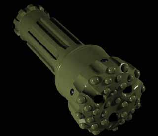
58 Hammers Percussion Hammers Impax hammer unifies durability and performance for deep-hole drilling The Impax* hammer features a patented hardened-steel guide sleeve that significantly optimizes energy transfer between the hammer s piston and bit. The guide sleeve design also significantly improves deep-hole drilling reliability by eliminating the plastic blow tube: a component that often causes conventional hammers to fail when they are subjected to shock, vibration, abrasive wear, and high-temperature erosion caused by misting. Because high-back pressure, circulation volume, and the water produced from misting and influx are major causes of hammer bit failure, the Impax hammer s lower chamber has been designed to handle 10% to 20% more water than conventional hammer bits. When water incursion forces those bits to be tripped out of the well, the Impax hammer s combined capabilities enable it to endure deephole drilling conditions while delivering reliable performance. Impax hammers are available in 8-, 10-, and 12-in sizes. 1 Impax Retention System Impax bit s proven retainer design protects the bit head from being lost downhole, thereby eliminating sidetracking or fishing costs. 1. A set of split retaining rings at the top of the bit ensure bit head retention The Impax bit retainer is a sleeve trapped between the shoulders of the driver sub and the hammer s case. The retainer catches the bit head when a shank (fracture in the spline area) prevents the retention rings from functioning The secondary catch mechanism is a rope thread, which is machined on the retainer ID and bit OD. When tripping out, rotating the drillstring to the right virtually eliminates any chance that the bit head will come out of the retainer. 54
 hammer bits feature a hardened steel guide sleeve instead of the conventional blow tube, optimizing energy transfer between the piston and the bit.")
59 Hammer Bits Impax Diamond-Enhanced Insert Hammer Bit Superior reliability, durability, and performance in hard formations. Impax diamond-enhanced insert (DEI) hammer bits feature a hardened steel guide sleeve instead of the conventional blow tube, optimizing energy transfer between the piston and the bit. Replacing the plastic blow tube increases reliability by eliminating failures due to high temperature, erosion, shock and vibration, and abrasive wear. The large lower chamber increases performance in the high backpressure conditions created by deep-hole drilling, high circulation volumes, and misting and influx. Impax hammers can handle 10%-20% more water volume from mist or influx than conventional hammers, saving a trip when water incursion would cause a conventional hammer to be tripped out of the well. Dual retention system When encountering hard rock formations that require the use of a percussion hammer, Impax bits offer a highly reliable retention system that prevents the loss of the bit head in the hole and saves the cost of fishing or sidetracking. Increased footage at lower cost Impax hammer bits have tough and durable DEIs that increase the footage drilled and lower the cost per foot. These bits eliminate the need for reaming, extending the life of the subsequent bit and providing a quality borehole for running casing. In addition, three exhaust ports improve bit-face cleaning for longer life and better ROP. The bit can be supplied with a concave bottom, which optimizes directional control. DIGR diamond in gauge row hammer bits DIGR* hammer bits are the cost-effective choice for drilling applications that do not require cutting structures with 100% DEIs. They offer a full range of options for cutting structure layout, but use DEIs only in the gauge row, providing excellent ROP and durability in less demanding formations. DIGR bits use the same retention system as Impax bits. The system s primary retention mechanism is a set of split retaining rings at the top of the bit. The bit retainer is a sleeve that is trapped between the shoulders of the driver sub and the hammer case. It catches the bit head in the event that a shank (fracture in the spline area) prevents the primary retention rings from functioning. The secondary catch mechanism is a rope thread machined on the retainer ID and on the bit OD. During the trip out of the hole, righthand rotation of the drillstring virtually eliminates any chance of the bit head coming out of the retainer. For conventional hammer bits, split rings are the only means of attachment to the drillstring, and the possibility of losing the bit head is so great that the bits have built-in fishing threads to facilitate retrieval. Impax Nomenclature 086 H D Diamond Enhanced Insert Number adjacent to Gauge Inserts Number of Gauge Inserts H Hammer Bit Indicator Diameter, x/8 in 8 3/4-in H1512D 55
 F Flat Profile G Diamond on Gauge M Modified Profile N Nonretainable PD Optional Gauge Protection R Retainable T Retainable V Thread V Concave Profile X Convex Profile 6 6/8-in [18-mm] Diameter")
60 Hammer Bits Nomenclature and Optional Features Impax Nomenclature and Features Size, 1/8 in Type Available Features 6 3/8-in H1006DX6RPD Impax Features C Carbide Insert D Diamond Enhanced Insert (DEI) F Flat Profile G Diamond on Gauge M Modified Profile N Nonretainable PD Optional Gauge Protection R Retainable T Retainable V Thread V Concave Profile X Convex Profile 6 6/8-in [18-mm] Diameter DEI 7 7/8-in [22-mm] Diameter DEI 61 H0806 X,6,R,D,PD 62 H1006 X,6,R,D,G 63 H1006 X,6,R,D,G 64 H1006 X,6,R,D,G 66 H1006 X,6,R,D,G 77 H1209 V,7,R,D,PD 83 H1209 V,7,R,D,PD 84 H1209 V,7,R,D,PD 86 H1206 V,7,R,D,PD 86 H1209 V,7,R,D,PD 87 H1209 V,7,R,D,G,PD 87 H1512 V,6,R,D,G,PD 94 H1509 V,7,R,D,PD 95 H1509 V,7,R,C,D,PD 96 H1509 V,7,R,C,D,PD 97 H1509 V,7,R,C,D,PD 105 H1509 V,7,R,D,PD 110 H1209 V,7,R,D,PD 122 H1209 V,7,R,D,G,PD 123 H1209 V,7,R,D,G,PD 146 H1812 V,7,R,D,G,PD 174 H1809 V,7,R,D,G,PD 56
61 Hammer Bits Nomenclature and Optional Features Bit Profile Shapes F Feature Flat Feature: Flat bottom with a single gauge-angle bit head profile Advantage: Allows use of heavier-set cutting structures on the bit face Benefit: Excellent drilling performance in hard formation intervals M Feature Modified Feature: Nonstandard bit head profile Advantage: Unique geometry incorporated for specific operating parameters Benefit: Enhanced performance for special drilling applications V Feature Concave Feature: Concave bottom with a dual gauge-angle bit head profile Advantage: Additional drilling stability and directional control Benefit: Excellent drilling performance in medium-soft to medium formation intervals where hole deviation is a primary concern X Feature Convex Feature: Flat bottom with a dual gauge-angle bit head profile Advantage : Allows use of heavy-set face and gauge cutting structures Benefit: Excellent drilling performance in medium to medium-hard formation intervals Gauge Reinforcement PD Feature Optional Gauge Protection Feature: All diamond gauge reinforcement Advantage: Significantly extends the life of the bit gauge Benefit: Eliminates the need for reaming (the practice of reducing the hole size after pulling out a nonpd hammer bit), increasing the life of the subsequent bit and providing a quality hole for running casing Gauge Inserts G Feature Diamond (DEI) in Gauge Row Feature: A cutting structure with carbide face inserts and DEI gauge inserts Advantage: Exceptional gauge durability and abrasion resistance Benefit: Excellent bit gauge life when drilling long, medium-soft formation intervals Face Inserts C Feature Carbide Insert Feature: All carbide cutting structure Advantage: Excellent durability and abrasion resistance Benefit: Superior and cost-effective drilling performance in soft to medium-soft formations D Feature Diamond-Enhanced Insert (DEI) Feature: All DEI cutting structure Advantage: Exceptional durability and abrasion resistance Benefit: Excellent drilling performance in longer intervals through hard formations 6 Feature 6/8-in [18 mm] Diameter DEI Feature: 6/8-in diameter DEI gauge cutting structure Advantage: Allows use of heavy-set diamond gauge cutting structures Benefit: Eliminates the need for reaming, increasing the life of the subsequent bit and providing a quality hole for running casing 7 Feature 7/8-in [22 mm] Diameter DEI Feature: 7/8-in diameter DEI gauge cutting structure Advantage: Allows use of diamond gauge cutting structures with improved impact-damage resistance Benefit: Eliminates the need for reaming, increasing the life of the subsequent bit and providing a quality hole for running casing Bit Head Retention N Feature Nonretainable Feature: No retaining feature on the bit head (standard fishing threads) Advantage: Compatibility with third party hammers that have no bit retention features Benefit: Flexibility to use the bit in various BHA assemblies such as those used for water wells, construction, etc. R Feature Retainable Feature: Patented bit head retention system Advantage: Prevents loss of the bit head in the hole Benefit: Saves the cost of sidetracking or fishing T Feature Retainable V Thread Feature: Slightly modified patented bit head Advantage: Allows bits with larger diameter shanks to be run with our patented retention system Benefit: Saves the cost of sidetracking or fishing 57
62
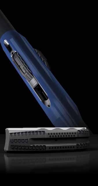

63 Borehole Enlargement 59
64 Borehole Enlargement Rhino* Integrated Borehole Enlargement System - Rhino XS* Hydrailically Expandable Reamer - Predator* Cutter Blocks - Rhino stabilizer PDC Hole Openers - Staged Hole Openers Quad-D* Dual-Diameter Drift and Drill Bi-center - Quad-D Reamer* - Quad-D Bits* Roller Cone Under-Reamers and Hole Openers - Reamaster-XTU* Forged Cutter-Arm Under-Reamer - Drilling-Type Under-Reamer (DTU) - Heavy Duty Hole Opener (HDHO) 60

65 Borehole Enlargement Rhino XS Hydraulically Expandable Reamer Borehole enlargement while drilling, with high-quality, concentric boreholes for improved casing running and uniform cementing clearance. Rhino XS* hydraulically expandable reamers consistently provide a wellbore quality not achievable with other reaming tools, while demonstrating superior reliability. They are primarily used with rotary steerable drilling systems, and are the concentric reamers of choice for a variety of challenging applications, including deep water drilling extended intervals with rotary steerable systems (RSS) extended-reach drilling (ERD) backreaming in loosely consolidated formations drilling highly abrasive formations scale removal inside production casing tight-tolerance casing designs. Concentric, full-gauge borehole The balanced-mass design of the Rhino XS reamer minimizes vibrations, eliminating the likelihood of undergauge and irregular boreholes. Integrated jet nozzles and flow paths improve evacuation of cuttings while drilling. Once hydraulically activated, the reliable Z-Drive* reamer cutter block deployment system transfers downhole weight to the reamer, pushing the cutter blocks upward and radially outward to the fully open position. This facilitates rapid cutout and ensures a full-gauge, concentric borehole. Dependable retraction to minimize stuck tools Dependable retraction of the cutter blocks with the Z-Drive system helps to avoid stuck BHAs. Application-specific and robust construction The single-piece body allows for higher tensile- and torque-load capacity. The tool features a symmetrical, concentric arrangement of three PDC cutter blocks that improve ROP without sacrificing durability. IDEAS* integrated drillbit design platform provides applicationspecific cutter blocks optimized for bit and BHA dynamics, and formation lithology for any hole-enlargement-while-drilling requirement. The reamer placement and operating parameters are also optimized for performance with the rest of the BHA components. Optional features DBD deactivation system: The Rhino XS reamer can be locked in a closed position to avoid damaging the casing while running in. Once below the casing shoe, hydraulic actuation can be enabled by dropping an activation ball to unlock the tool. Switching the rig pumps on and off will now open and close the tool. The DBD deactivation system disables the hydraulic actuation and closes the tool on demand by dropping a second, larger-diameter ball. Once the tool is closed, full circulation can be established at the drill bit for increased bit flow rate. Cement cleanout blocks: These are designed to remove a cement sheath below a restriction inside the casing, without damaging the casing. 61

66 Borehole Enlargement Predator Cutter Block IDEAS design platform is used to design Predator cutter blocks optimized for bit and BHA dynamics, and for specific target lithologies such as salts, shales, or lower compressive strength sands. This process minimizes the harmonic signature of the Rhino XS reamer in the BHA and improves drilling performance. Using the dynamic IDEAS* platform, Smith Bits engineers test each precisely engineered Predator* cutter block design and its optimized gauge configurations to be used with Rhino XS* reamers. After identifying the design that provides the best simulated performance, results are verified in field applications. Integrated design for superior performance Field results have confirmed a step change in drilling performance when these new components are used in conjunction with an appropriately modeled pilot bit. This integrated systems approach ensures that the reamer, the bit, and the other components of the BHA work synergistically to minimize vibration, drill a high-quality enlarged wellbore, and provide maximum ROP. More footage at maximum ROP The hydraulically actuated, single-piece cutter blocks have a high tensile- and torque-load capacity. ONYX* PDC cutters are available for the toughest applications. These cutters are more thermally stable, as well as more wear- and impact-resistant than other PDC cutters, both standard and premium. They remain sharp longer, translating into more footage drilled at maximum ROP over a wide range of applications, from hard, highly abrasive to interbedded, difficult-to-drill formations. Stabilizer/Gauge Pads Maintains hole gauge and improves stability Formation Cutting Structure Designed in IDEAS to reduce vibration and improve ROP Z-Drive Tongue & Groove Actuation For reliable block deployment and retraction Backreaming Cutting Structure Ensures borehole quality in all formation types 62
67 Borehole Enlargement Rhino XS Reamer Specifications Rhino XS Reamer Specifications Tool Series Overall Body Diameter, in Standard Fishing Neck Diameter, in Enlarged Hole Size, in Minimum Pilot Hole Size, in Internal Bore Diameter, in / /2 3 3/ /2 5 1/2 4 1/ /4 6 1/ / /4 6 1/ / /4 6 1/2 7 3/8 6 1/ / /2 6 3/ / / / / / /4 8 1/ /4 10 1/4 11 3/4 9 1/ / /2 10 1/ /2 11 3/4 13 1/2 10 7/ / / /4 14 1/ / /4 18 1/4 14 1/ / / / / / / Maximum Thru Flow, gpm 63

68 Borehole Enlargement Rhino Stabilizer As well profiles and the individual components in modern drillstrings become more complex, minimizing drillstring vibration becomes an increasingly important factor in building a quality wellbore. Reduced drillstring vibration The Rhino* stabilizer significantly reduces drillstring vibration in borehole enlargement operations, thereby increasing the life of downhole tools and surface equipment; improving ROP; delivering a smooth, full-gauge borehole; and minimizing the chance of losing the BHA in the hole. The tool uses three abrasion-resistant stabilizer blocks with the Z-Drive* reamer cutter block deployment system. When run above the Rhino XS* reamer, the Rhino stabilizer provides concentric, stable points of contact in the enlarged hole section, increasing lateral support. Superior wear resistance Availability of tungsten carbide inserts and diamond-enhanced inserts in the stabilizer blocks provides superior wear resistance. Stabilizer activation method is ball drop, the same as the Rhino XS Reamer. Configuration is typically run undergauge and feet above the Rhino XS Reamer. Rhino Stabilizer Block Diamond-Enhanced Gauge Inserts Z-Drive Tongue & Groove Actuation Stabilizer Blocks Provide Concentric Stabilization Tungsten Carbide Hardfacing 64
69 Borehole Enlargement Rhino Stabilizer Specifications Rhino Stabilizer Specifications Tool Series Overall Body Diameter, in Standard Fishing Neck Diameter, in Enlarged Hole Size, in Minimum Pilot Hole Size, in Internal Bore Diameter, in Maximum Thru Flow, gpm /4 6 1/ / / /2 6 3/ / / / /4 8 1/ /4 10 1/4 11 3/4 9 1/ / /2 10 1/ /2 11 3/4 13 1/2 10 3/ / / /2 16 1/2 13 1/ /4 18 1/4 14 3/ / / / /
70 Borehole Enlargement Concentric Staged Hole Openers (SHO) Concentric Staged Hole Openers (SHO) from Smith Services have been developed from a tradition of application know ledge and technical excellence gained from the success of Quad-D* dual-diameter drift and drill, reaming products. Superior borehole quality and high ROP The staged hole opener (SHO) incorporates precision-engineered cutting structures to ensure fast, smoothly drilled, high-quality, concentric hole opening under a wide range of application conditions. SHO tools are run successfully on rotary and rotary steerable assemblies in both straight and deviated holes.while the overall cutting structure is balanced, it is divided into four sections, each serving a specific purpose. Stage One Pilot Bit The pilot bit, either fixed cutter or roller cone, drills the initial hole diameter. A bull nose can also be used to follow a predrilled pilot hole. SHO assemblies can be used with multiple pilot configurations for specific applications, and can be positioned for various drillstring configurations. Stage two SHO pilot section The pilot section consists of one or two rows of cutting structures to recondition the pilot hole and remove any swelling clays or moving halites. Gauge pads provide initial stabilization as the SHO begins the staged reaming process to reduce stick/slip, whirling, or off-center tendencies. Stage three SHO pilot conditioning section (PCS) The cutting structure is designed to minimize work rates on each cutter position for maximum durability. By stress-relieving the formation with this intermediate stage, larger-hole drilling can be done at a more aggressive ROP. The third stage recentralizes the SHO on the given well trajectory in both vertical and directional applications. Gauge pads and gauge trimmers provide the main stabilization for the SHO. Gauge pad lengths in the section may vary depending on whether the application calls for a near-bit or drillstring placement. Stage four SHO reaming section This cutting structure completes the final hole diameter. With the formation already stress-relieved, the reaming section remains aggressive even in more competent formations. Gauge trimmers and spiraled gauge pads ensure good hole quality. Gauge pads in this section are kept short in length for directional responsiveness. Type Size, in Pilot, in SHO SHOS SHO SHOSI /2 SHO / /4 SHOSI / /4 SHOSI /4 SHO /4 SHO /4 SHO / /4 SHOI / SHO SHO /2 8 1 /2 SHO /4 8 1 /2 SHOSI /4 8 1 /2 SHO /8 8 1 /2 Staged Hole Openers Nomenclature S H O S i SHOI /8 8 1 /2 SHOS /2 6 1 /8 SHOS /2 6 1 /8 Cutter Size Blade Count IDEAS Designed SHARC Feature SHO - Staged Hole Opener 66

71 Borehole Enlargement Reamaster-XTU Underreamer The Reamaster-XTU* forged cutter arm underreamer, has been designed with two large, robust cutter arms which facilitate increased cross-sectional area at the underreamer cutter pockets. This also provides more room for larger sealed bearing and PDC cutters for optimized underreaming performance. Gun-drilled ports through the tool deliver more fluid, giving the operator greater control over the distribution of fluid across the bit and the underreamer cutters. The ability to run more drilling weight on the tool and spend more time on bottom results in cost-effective under reaming. The ability to ensure an existing pilot hole up to 70 percent makes this product ideal for a range of drilling and remedial operations. Fluid flow has been optimized using gundrilled ports to deliver more drilling mud to the underreamer cutters and the drill bit. This improves hole cleaning efficiency and accommodates the fluid requirements of other downhole tools. Features and Benefits Forged cutter arms to withstand high shock and torque loads Sealed bearing cutters to provide longer on-bottom life Positive lock to keep arms in the open position Optimized fluid distribution Strategically placed nozzles Milled tooth, TCI and PDC cutting structures are available for a broad range of applications Milled Tooth Cutter TCI Cutter Customized cutting structures are available for a broad range of applications and formation types. Sealed bearing milled tooth and TCI cutters are designed specifically for underreaming operations and are capable of delivering penetration rates and cutting structure life comparable to the drill bit. PDC cutters are also available for long intervals. Applications Enlarge wellbore size below a restriction Minimum clearance and expandable casing programs Underreaming while drilling Gravel packs and expandable-screen completions Ream out key seats and clean up downhole ledges PDC cutter Reamaster-XTU Underreamer Specifications Tool Series Opening Diameter, in Pilot Hole Size, in Collapsed Body Diameter, in Fishing Neck Length, in Fishing Neck Diameter, in Overall Length, in Top Pin/ Bottom Box Connection, Reg /2, 9 5 7/8 6 1/2 5 3/ / / , 11 3/4, 12 1/4 7 1/ / / / /8, 10 5/8, 11, 12 1/4, 13 1/2 8 1/2 9 7/8 8 1/ / / /4, 13 1/2, 15, /8 12 1/4 9 1/ /8 1, , 15, 16, 17 1/2 12 1/4 14 1/2 11 3/ /8 1, , 22, 24, / /8 3,200 Approximate Weight, lbm Ordering instructions, please specify: Top and bottom connections Fishing neck diameter Opened diameter Size and weight of casing to be run through, if available Bullnose ordered separately Type of cutting structure (milled tooth, TCI or PDC) U.S. Patent Numbers: Underreamer 4,660,637 PDC Underreamer 4,431,

72 Borehole Enlargement Quad-D Reamer The versatility of Quad-D* dual-diamter drift and drill products is best demon strated by the range of applications that they drill. The GeoReam* dual-diameter near-bit reamer, is well suited to be run directly above the pilot bit for directional applications and it is the recommended alternative to the Quad-D bit in appli cations in which a PDC cutting structure is not the best option for the pilot bit. Although compact in length, the stability-enhancing technology used in the GeoReam ensures optimal hole quality while drilling. With longer pilot conditioning sections and drill string connections, Quad-D Reamers are designed to maximize performance in rotary applications. The longer pilot conditioning section acts like a string stabilizer to ensure centralization and stabili zation. This tool is intended to be run with various BHA configurations, including rotary steerable systems. Features and Benefits Directional & BHA flexibility for precise control of wellbore Drill-out capability for eliminating trips Diameter control for full gauge wellbore Formation-specific design for optimized drilling efficiency The QDR has drill collar connections for string placement Fishing Neck 8½ in 9 7 8in QDG5216 Tong Neck Type Size, in Drift, in QDGS QDG /8 QDG QDG QDG ½ 14½ QDG /8 QDG ½ QDG ¾ 12¼ QDG ½ 12¼ QDG ¼ 12¼ QDG ¼ 10 5 /8 QDG ¼ 10 5 /8 QDG /8 8½ QDG5313 8½ 7½ QDG QDG5209 6½ 5 7 /8 8½ in 9 7 8in QDR5313 Type Size, in Drift, in QDRS ½ QDR ½ QDRS ½ 14½ QDR ½ QDR ¾ QDR ¾ 12¼ QDR ½ 12¼ QDR ¼ 12¼ QDR ¼ 10 5 /8 QDR ¾ 9½ QDR /8 8½ QDRS /8 6 5 /8 Quad-D Nomenclature Q D G Cutter Size Reamer Blades to Full Diameter Pilot Blade Count G/R - GeoReam or Reamer Product Quad-D Technology 68


73 Borehole Enlargement Quad-D Bi-Center Bits Quad-D dual-diameter drift and drill bi-center bits provide hole opening through installed casing or liner sections. 16½-in 20-in QDS7313PX 14¾-in Hole Maintained This family of aggressive matrix and steel body bits is designed to provide durability, reduce torque response, maintain tangents, and reduce sliding time without compromising efficiency when drilling either float equipment or formation. It features a strong, one-piece construction and a very low overall height that enhances directional capabilities when drilling with downhole motors. Vibration is controlled by force and mass balancing, employment of spiral blades and gauge, asymmetrical blade layout, and use of Lo-Vibe* inserts. Because of the resulting bit vibration control, bit rotation is maintained about the true bit axis ensuring accu- rate finished hole diameter and quality. Hydraulic ports are positioned to provide efficient cuttings removal and cleaning of both the pilot and reaming sections. A unique gauge profile prevents cutters from contacting and damaging the casing and also provides a high degree of stabilization and gauge protection. Quad-D* dual-diamter drift and drill bi-center bits have achieved success in a broad range of applications. Features and Benefits Drill-out capability for eliminating trips Directional responsiveness for precise control of wellbore Diameter control for full gauge wellbore Formation-specific design for optimized drilling efficiency Type Size Availability, in QDM3209 3¾ 4 1 /8 QDM /8 6½ Pilot gauge section QDM4209 3¾ 4 1 /8 QDM QDM QDM7313 8½ 9 7 /8, 10 5 /8 12¼ QDMS4209 3¾ 4 1 /8 QDS3209 4¾ 5 5 /8, 4½ 5¾ QDS ¾ 5 5 /8, ¼-in 14¾-in QDS7213 Quad-D Nomenclature Q D S QDS /8 QDS5213 8½ 9 7 /8, 12¼ 14¾, 14½ 17½ QDS5216 8½ 9 7 /8, 14½ 17½ QDS QDS6309 6½ 7½, 8½ 9 7 /8 QDS ¼ 14¼ QDS QDS7313 7½ 8½, 8½ 9 7 /8, 9½ 11, 10 5 /8 12¼, 16½ 20 Cutter Size Reamer Blades to Full Diameter Pilot Blade Count M/S - Matrix or Steel Quad-D Technology 69
74 Borehole Enlargement Drilling-Type Underreamer The Drilling-Type Under reamer (DTU) is designed to run in conjunction with a drill bit or a bullnose depend ing on pilot hole condition or project objec tives. The tool s three retractable cutting arms are opened and held in position by continuous hydraulic pressure. The three-arm design allows the pilot hole diameter to be increased up to 75 percent, depending on tool size. Cutters are retracted by disengaging the pump, allowing the tool to be repositioned for selective underreaming operations or retrieval from the well. Piston spring assists with arm retraction following inter ruption of hydraulic pressure. Features and Benefits API Reg box down for make up to bit or jetted bullnose Milled tooth, TCI or PDC cutters Facilitates fluid passage to the bit or jetted bullnose Cutter arms changeable quickly on the rig floor Applications Wiping out bridges and key seats Drilling and underreaming in fault zones and swelling formations Opening the reservoir section for gravel packing Underreaming while drilling in certain applications DTU w/ Bullnose Drilling-Type Underreamer Specifications Tool Series Standard Opening Diameter, in Optional Opening Diameter, in Body Diameter, in Collapsed Diameter, in Fishing Neck Length, in Fishing Neck Diameter, in Overall Length, in Top Pin/ Bottom Box Connection, Reg Approximate Weight, lbm , /8, 8 5/8 3, / , /8, 8 5/8 4, Minimum Pilot Hole Diameter, in Bullnose Specifications Top Pin Connection, Body Diameter, in Nominal Length, in Reg 2 5/8 3 5/ /2 4 3/ /2 6 1/ /2 7 1/ / / / Ordering instructions, please specify: Tool series Top and bottom connections Fishing neck diameter Expanded diameter Casing size and weight, when applicable Bullnose ordered separately Type of cutting structure (milled tooth, TCI or PDC) Bullnose Notes: Standard bullnose includes one replaceable down jet Reverse jet option must be requested Specify jet size(s) 70


75 Borehole Enlargement Heavy-Duty Hole Openers (HDHO) The Heavy Duty Hole Openers (HDHO) is designed for use in soft clays and shales to mediumhard shales and limestones, and is particularly effective in sticky formations where balling problems are encountered. Three jets with replaceable nozzles continuously clean the tool s cutting structure, clearing debris build-up and increasing penetration. A range of milled tooth and TCI cutting structures are available for a variety of formation conditions. The Hole Opener is available in sizes 6¼ inches through 42 inches, with hand-tool demountable cutters to speed redress and reduce downtime. Features and Benefits Demountable cutters easily replaced on the rig floor Three replaceable jets clean cutting surfaces and prevent balling, ensuring fast penetration and effective hole cleaning Sealed bearings and TCI cutters available for most hole diameters Upjets to aid in cuttings removal Robust tool for drilling longer intervals HVOF carbide coating to reduce body erosion Note: Tools 36 in hole size and up are designed with four arms and cutters. Applications Top hole enlargement to accommodate drive pipe, conductor casings and large-diameter surface casings Hole opening at river crossings, or other types of formations where balling problems are encountered Borehole enlargement in soft to hard formations Notes: Bullnose is available upon request. Cutter bearing rebuild kits are available on special order. Ordering instructions, please specify: Pilot hole size Hole opening size Top and bottom connections, if other than standard Fishing neck diameter, if other than standard Milled tooth or TCI cutters Heavy Duty Hole Openers with OD less than 26-in have 3 cutters Heavy Duty Hole Openers with OD 26-in or larger have 4 cutters 71
76


77 Reference Tools 73
78 Reference Total flow area chart Total Flow Area (TFA) of Standard Nozzles, in 2 Number of Nozzles Nozzle Size, in 7/ / / / / / / / / / / / / / / / / / / / / / / / / /
79 Reference Recommended fixed cutter bit makeup torque Recommended Makeup Torque Diamond & Fixed Cutter Drill Bits With Pin Connections API Reg Connection Size, in Bit Sub OD, in Minimum, ft.lbf Normal, ft.lbf Maximum, ft.lbf 3 1,970 2,280 2, /8 3 1/8 2,660 3,100 3, /4 3,400 3,950 4, /8 3 1/2 3,380 3,950 4, /4 & Larger 5,080 5,900 6, /8 5,700 6,600 7, /2 4 1/4 6,940 8,050 8, /2 & Larger 8,400 9,850 10, /2 13,700 16,600 17, /2 5 3/4 18,100 21,100 22, /2 & Larger 18,550 21,600 22, /8 7 1/2 40,670 47,300 50, /4 & Larger 41,050 47,800 50, /2 53,100 61,850 65, /8 8 3/4 63,500 73,750 78,300 9 & Larger 68,600 79,800 84, / , , , /4 & Larger 107, , ,800 Notes: 1. Recommended make-up torque dictated by all BHA components 2. Higher makeup torque values within the above ranges are recommended when high WOB is used. 3. Box connection bits should use makeup torque values between Minimum and Normal. 4. All connections must be lubricated with a joint compound meeting API requirements. Recommended roller cone bit makeup torque Size Range API Pin Size Recommended Torque in mm in mm ft.lbf N.m 3 1 /2 4 1 /2 4 5 / /8 7 3 /8 7 1 / /8 Reg 2 7 /8 Reg 3 1 /2 Reg 4 1 /2 Reg Bit size, in Fixed Cutter, in Roller Cone, in 6 3/4 and smaller / /32 to /32 9 1/32 to 13 3/ / /32 to 17 1/ / /32 and larger / ,000 3,500 4,500 5,500 7,000 9,000 12,000 16,000 4,000 4,800 6,000 7,500 9,500 12,000 16,000 22, / /8 Reg ,000 32,000 38,000 43, / / /8 Reg or 7 5 /8 Reg 7 5 /8 Reg or 8 5 /8 Reg 168 or or 219 Makeup torque must correspond to API pin connection for each bit size. Note: Some of the above bit sizes are available on special order with alternate pin connections. 34,000 40,000 40,000 60,000 46,000 54,000 54,000 81,000 API gauge tolerances for fixed cutter and roller cone bits 75
80 Reference Field operating procedures for fixed cutter and roller cone drill bits BIT PREPARATION Bit Handling at rig site Bit cutting elements with diamond both fixed cutter and roller cone bits, are brittle and susceptible to impact damage. Care should be taken when handling or removing any bit containing diamondcutting elements. Do not drop the bit even if it is in the container. Use a piece of wood or rubber under the bit face. Bit Inspection Inspect bit for integrity (cutting elements, pin connection and makeup shoulder). Ensure there are no foreign objects or obstructions in the internal fluid passageways. Verify TFA on bits with fixed TFA. Record bit size, type and serial number. Nozzle Installation Ensure that nozzle series are correct for bit type. Gauge the orifice size of every nozzle to ensure proper total flow area (TFA). Remove the plastic plug and ensure that O-rings are properly installed and seated. If different size nozzles are to be used ensure that the correct sized nozzles are in the correct place. Put bigger size nozzles in the in the center of the bit. Ensure that the threads are clean and greased (any petroleumbased grease). Fixed cutter bits with matrix threads should not be greased. Grease the nozzle body below the threads to prevent O-ring damage. Screw the nozzle in by hand until snug. Use nozzle wrench for final tightening. Excessive force is not necessary and can damage the carbide nozzle. If nozzle sizes below 9/32 are to be used, recommend the use of drill pipe screens and / or a float to prevent reverse circulation plugging. Use grasshoppers if necessary. Makeup Ensure that the appropriate bit breaker is with the bit. Inspect to insure good condition and that it fits properly. Remove the bit from the box and place face down on a piece of wood or rubber. Engage the bit breaker with the bit and move them onto the rotary table. A float above the bit should be installed, especially on extended nozzle roller cone bits, in areas that tend to plug. Engage the hanging box connection to the doped threads of the bit pin. Proper makeup for small diameter bits is to makeup by hand for several turns, then place in the bit breaker and makeup to the recommended torque. Uncover the rotary and locate the bit and breaker onto the breaker holder. Makeup applying the recommended torque. Makeup torque specifications are from API spec RP7G. Roller Cone Bits Keep BHA as vertical as possible when making up bit to ensure no damaging contact between the nozzles (full-extended or mini s) and the bit breaker occurs. TRIPPING IN THE HOLE Identify potential problem areas before tripping. Trip slowly through BOP, doglegs, tight spots, ledges, casing shoes, cementing equipment, etc. Wash and or ream as necessary. Severe problems may require a special cleanup run. Roller cone bit legs will yield slightly and the bit can be rotated slightly in order to pass through some tight spots. Fixed cutter bits do not yield. Bits with PDC cutting elements are susceptible to impact damage. PDC bits are more susceptible to damage during tripping in the hole than roller cone bits. Certain types of fixed cutter bits with low junk slot area can create higher surge and swab pressures than roller cone bits due to more restrictive annular space. Local knowledge/practice will typically dictate wash down and reaming procedures. Minimum recommendation is to wash down at least the last joint to bottom at reaming speed with full circulation. Preference is to ream the last stand / 90 feet at reaming speed with full circulation. TAGGING BOTTOM Approach the hole bottom cautiously, monitoring WOB and torque. An increase in WOB or torque will indicate either contact with the hole bottom or fill. Fixed cutter bits will typically show an increase in torque first. Bit is on bottom when torque increases with the WOB. Difference between measured depth and contact point should be depth of fill. If fill is present, pick up above the fill and rotate to bottom with full circulation until bottomhole contact is assured. Regardless if fill is present, the pipe should always be reciprocated off-bottom. On rotary assemblies, use a maximum of 500 pounds per inch of bit diameter, 40 to 60 rpm. On motor assemblies, use a maximum of 500 pounds per inch of bit diameter and the minimum allowable rpm. Do not use high WOB when in fill. This could cause the bit to ball. Circulate and rotate off-bottom (as close as possible preferably less than 6 in, no more than 1 foot) enough (5 to 15 minutes, application dependent, recommend 15 min as minimum) to ensure the hole bottom is clear of fill or junk. 76
81 Reference Field operating procedures for fixed cutter and roller cone drill bits DRILLING CEMENT PLUGS, FLOAT EQUIPMENT AND CASING SHOES When using fixed cutter bits to drill out, ensure that all cementing equipment (plugs, float collars and shoes) is PDC drillable (nonmetallic, rubber, nylon, plastic or cement). Recommend the use of non-rotating plugs. Alternatively, it is preferable when cementing to pump some cement on top of the plug to help prevent it from rotating during drill out. Using the maximum allowable flow rate to assist cleaning is preferred, but may not be possible with motor assemblies. Procedure Frequently raising and lowering the bit while continuing circulation and rotation will help keep the bit clear of debris. Flushing after every 1 to 2 in drilled while reciprocating 3 to 4 feet will ensure debris is removed and new material is being drilled. Should the penetration rate decrease suddenly, repeat this step until it resumes. Do not spud. Spudding (impacting on the hole-bottom) can damage cutting structure elements on both fixed cutter and roller cone bits. It can also damage the roller cone bearing / seal system. Monitor pump pressure to ensure nozzles do not become plugged. Change rpm if bouncing or erratic torque is encountered. Fixed Cutter Bits On rotary, use the maximum flow rate with less than 6000 lbf WOB and rpm. On motor assemblies, drill with less than 6000 lbf WOB and the minimum allowable rotary rpm. Local practice will dictate flow rate as a compromise is needed between providing adequate cleaning and minimum rpm. Maintain low and consistent torque. Roller Cone Bits On rotary, drill with 2000 to 3000 lbf per inch of bit diameter and 40 to 60 rpm. On motor assemblies, drill with 2000 to 3000 lbf per inch of bit diameter and the minimum allowable rotary rpm. Local practice will dictate flow rate as a compromise is needed between providing adequate cleaning and minimum rpm. Bouncing or erratic torque may indicate locked cones. Temporarily increase the weight to ensure cone rotation, then reciprocate the bit slightly off-bottom while continuing circulation and rotation to help clean the bit. Resume with original parameters when the bouncing or erratic torque has been eliminated. Maintain minimum WOB / torque to prevent wiper plugs from rotating. Erratic torque may indicate a rotating plug. Rotating Plugs Should a plug begin to rotate, set down on plug with no rpm Increase WOB until 2000 to 3000 lbs. per inch of bit diameter is reached or alternatively an increase of 300 psi over the normal standpipe occurs. Then begin rotation, ending with 40 to 60 rpm. Repeat until penetration is achieved and wiper plug is drilled. Alternative procedure (last resort) Rotate bit at rpm Use 500 pounds / inch of bit diameter Alternate using no flow rate for 1 minute to full flow for 30 seconds. ESTABLISHMENT OF Bottomhole PATTERN Bottomhole pattern break-in is considered to be when a new bit achieves uniform cutting structure loading. Proper break-in is critical to durability and ROP. After drilling out the casing shoe, establish the bottomhole pattern. There may be some BHA dictated WOB and rpm guidelines until the BHA is below the casing shoe. Optimization of WOB and rpm may have to wait until the BHA or some portion of the BHA has cleared the casing shoe. Use extra care establishing a new bottomhole pattern when following a bit with a substantially different bottomhole profile, e.g., a PDC bit following a roller cone bit or vice-versa. Roller cone bits typically drill a larger size hole than a fixed cutter bit. Be sure to properly establish the bottomhole pattern when following a roller cone bit in order to insure stability. Establishment of bottomhole pattern can be dependent upon factors such as bit design, BHA, etc. Roller Cone Bits Break-in is done with light WOB and slow rpm and a new bottomhole pattern is normally achieved within 3 to 6 inches (assuming no tracking or off-center rotation). On rotary, use a maximum of 500 pounds per inch of bit diameter with 40 to 60 rpm. On motor assemblies, use a maximum of 500 pounds per inch of bit diameter and the minimum allowable rpm keep rotary rpm to a minimum rpm. Minimum allowable motor rpm can be formation dependent. Soft, balling formations should be entered with full flow rate. At that point, WOB and rpm can be gradually increased to typically operating levels or to initial drill-off test levels. Increase WOB first then rpm. 77
82 Reference Field operating procedures for fixed cutter and roller cone drill bits Fixed Cutter Bits Although a new bottomhole pattern is created in less than a bit diameter, it is preferred to drill 3 to 5 feet before increasing WOB and rpm. For starting parameters, use maximum flow rate, less than 6000 lbs. WOB and rpm. Maintain low and consistent torque changing operating parameters as needed. Take extreme care following a coring operation or bits of different types or profiles. A different existing profile can overload specific cutting elements potentially causing a premature failure RUNNING THE BIT Controlled Drilling If in or encountering a known hard or abrasive formation of short length with a dull bit, controlled drilling (sacrificing ROP) through the interval may enhance the following bit s performance. The dull condition and bit type will determine the feasibility. Monitor the ROP and torque, follow the recommendations for evaluating ROP and torque as listed below. Proceed only if ROP and increased risk is acceptable to the customer. Deviation & Directional Control Deviation concerns may override optimum WOB used. Typically minimum WOB is used to control deviation on rotary assemblies. Monitor deviation on straight holes. Reduce WOB to maximum allowable to maintain deviation specified by customer. Monitor for vibration. Generally, increase rpm to improve ROP. Higher torque and higher speed changes bit walk direction by making the bit attack the formation at different angle due to higher torque. The bit tries to climb the hole wall at a different position at different torque levels. High speed on turbines can make the bit change direction completely. Operational Parameter Guidelines Optimum WOB and rpm determined are for a particular application and can only be continuously used in a homogeneous formation. Therefore in intervals of various formations, ROP optimization tests will not produce the optimum weight and rotary combination. Drill off tests will be necessary anytime the formation changes. Typically a range of WOB and rpm combinations is derived for the interval, e.g., interbedded formations. PULLING THE BIT When economics dictates. When ROP dictates. Loss of directional characteristics Loss of pump pressure due to a washout. Roller Cone Bit When a substantial increase or dramatic fluctuation in torque is seen with low or high WOB and low ROP or when tagging bottom. Magnitude is typically area and application dependent. There is no 100% effective/reliable indicator. The best indicator is dramatic fluctuations of torque when tagging bottom. Formation Changes Formation changes can instigate both torsional and lateral vibrations. Monitor and adjust accordingly. When anticipating a harder/more difficult formation, to prevent impact damage, reduce the rpm maintaining WOB while still in the softer formation to help prevent initiation of lateral or torsional vibrations when the hard formation is encountered. After the formation is encountered, adjust the parameters or perform a drilloff test. If an unknown formation (anomaly/transition) is expected, reduce the rpm and the WOB to a minimum accepted level. Establish ROP and torque baselines at these levels. Monitor ROP and torque to determine when formation has been encountered and when through the anomaly. 78
83 Reference Measurement units and drilling formulas Standard Measurement Units Quantity/Property Units Multiply By To Obtain Symbol Depth ft meters m Weight on bit (WOB) lbf x 10-4 decanewton tonne Nozzle size 32nds in millimeters mm Drill rate ft/hr meters/hour m/hr Volume Pump output and flow rate Annular velocity and slip velocity Linear length and diameter barrels galus/stroke galus/min bbl/stroke x 10-3 cubic meters cubic meters/stroke dan tonne m 3 m 3 /stroke m 3 /min m 3 /stroke m 3 /min x 10-3 an oil barrel is cubic meters/minute cubic meters/stroke bbl/min x m 3 exactly cubic meters/minute ft/min meters/minute m/min in 25.4 millimeters mm Pressure psi kilopascals megapascals bar Mud density lbm/galus kilograms/cubic meter kg/m 3 Mud gradient psi/ft kilopascals/meter kpa/m Funnel viscosity s/qt (US) seconds/liters s/l Apparent and plastic centipoise 1 millipascal seconds mpa.s viscosity yield point Gel strength and stress lbf/100ft (0.5 for field use) pascals Pa Cake thickness 32nds in millimeters mm Filter loss mm or cc 1 cubic centimeters cm 3 Torque ft.lbf newton meters N.m kpa MPa bar Drilling Formulas Cost per Foot (CPF) Bit Cost + Rig Cost (Trip Time + Drilling Time) CPF = Footage Drilled Pressure Drop ( D) Flow Rate P = 2 x Mud Weight 10,856 x TFA 2 Flow Rate (Q) = (Pump Stks x Output/stk) Bit Pres. Drop ( P bit ) = (MWt. x Q 2 )/(10858 x TFA 2 ) Hydraulic Horsepower (HHP bit ) = ( P bit x Q)/(1714) HSI = (HHP bit )/(.7854 x D 2 ) Jet Velocity (JV) = ( x Q)/(TFA) Impact Force (IF) = (JV)x(MWt)x(Q)x( ) MWt = Mud Weight TFA = Nozzle Flow Area D = Bit Diameter Hydraulic Horsepower (HHP) (Bit Pressure Drop) (Flow Rate) HHP = 1,714 Hole Area (A h ) π x Hole Diameter A h = 2 4 Hydraulic HP per Square Inch (HSI) Hydraulic Horsepower HSI = Hole Area, in 2 79
84 Reference Drill collar specifications Drill Collar Weight (Steel), lbm/ft Drill Collar ID, in /4 1 1 /2 1 3 / /4 2 1 /2 2 3 / /4 3 1 /2 3 3 / / / / / / / / / / / Drill Collar OD, in 5 1/ / / / / / / / / / / /
85 Reference Conversion factors Fraction to Decimal 1 / / / / / / / / / / / / / / / / / / / / / / / / / / / / / / / / / / / / / / / / / / / / / / / / / / / / / / / / / / / / / / / English and Metric Multiply By To Obtain Acres 43,560 Square feet Acres Square miles Acres 4,840 Square yards Barrels, water 31.5 Gallons Barrels, water 263 Pounds Barrels, oil (API) 42.0 Gallons Barrels per day Gallons per minute Centimeter Inches Cubic centimeters Cubic inches Cubic feet 1,728 Cubic inches Cubic feet Cubic yards Cubic feet Gallons Cubic feet Barrels (oilfield) Cubic feet Liters Cubic feet Cubic yards Cubic feet per minute Liter per second Cubic inches Cubic centimeters Cubic yards 27 Cubic feet Cubic yards Cubic meters Degrees (angle) Radians Degree Fahrenheit (F) [Degree F-32] 1.8 (or x 5/9) Degree Celsius (C) Feet Centimeters Feet 12 Inches Feet Meters Feet Miles Feet of water (depth).4335 Pounds per square inch Feet Meters Foot pounds Joules Foot pounds Meter-kilograms Furlongs 660 Feet Gallons (imperial) Gallons (U.S.) Gallons (imperial) Liters Gallons (U.S.) 3, Cubic centimeters Gallons (U.S.) Barrels, oil Gallons (U.S.).1337 Cubic feet Gallons (U.S.) Liters Gallons per minute Cubic feet per second Gallons per minute 34,286 Barrels per day Grains Milligrams Grains Ounces Inches Feet Inches 25.4 Millimeters Inches of water Pounds per square inch English and Metric Kilometers 3,281 Feet Kilometers.6214 Miles Kilometers per hour.6214 Miles per hour Knots 6,080 Feet Knots Miles Knots per hour Miles per hour Liters Cubic feet Liters.2642 Gallons Meters Feet Meters Inches Meters Yards Miles 5,280 Feet Miles Kilometers Miles 1,760 Yards Miles per hour 88 Feet per minute Miles per hour Kilometers per hour Miles per hour.8684 Knots per hour Minutes Hours Minutes (angle) Radians Minutes (angle) 60 Seconds (angle) Ounces (fluid) Cubic inches Ounces per cubic inch Grams per cubic centimeter Paschal (unit or force, pressure) 1.0 Newton per square meter Pints Cubic inches Pints.125 Gallons Pounds Grams Pounds.4536 Kilograms Pounds of water Cubic feet of water Pounds of water Cubic inches of water Pounds of water.1198 Gallons Pounds per cubic foot Grams per cubic centimeter Pounds per cubic foot Kilograms per cubic meter Pounds per square foot Kilograms per square meter Pounds per square foot Newtons per square meter Pounds per square inch Feet of water Pounds per square inch Inches of mercury Pounds per square inch Newtons per square centimeter Quarts (U.S.) Cubic inches Quarts (U.S.) Cubic centimeters Quarts (U.S.) Liters Radians Degrees Radians per second Revolutions per minute Square centimeters.1550 Square inches Square feet 144 Square inches Square feet Acres Square feet 929 Square centimeters Square inches Square centimeters Square inches Square feet Square miles 640 Acres Square miles 2.59 Square kilometers Square kilometer Acres Square meters Square feet Square meters Acres Square yards 9 Square feet Square yards.8361 Square meters Temperature (degrees Cent.) 1.8 (add 32 deg.) Temp. (degrees Fahr.) Temperature (degrees Fahr.) 5/9 or (subtract 32 deg.) Temp. (degree Cent.) Tons (long) 2,240 Pounds Tons (metric) 2,205 Pounds Tons (short) 2,000 Pounds Yards.9144 Meters Yards Centimeters 81
86 Reference Buoyancy factor Buoyancy Factor k Mud Density k Mud Density kg/l lbm/galus lbm/ft 3 kg/l lbm/galus lbm/ft 3 k Apparent weight = Real Weight x Buoyancy Factor hence: Buoyancy Factor (k) = 1 - Mud Density Steel Density 82

87 Reference Fixed cutter bit nozzle installation Correct Nozzle Installation Helps Prevent Washouts Remove the plastic plug and the O-ring from each nozzle port. Grease the O-ring and replace it in the O-ring groove. Do not grease nozzles in Matrix bits before installation. Lightly grease nozzles in Steel bits and screw into jet ports. Hand tighten the nozzle with a tee wrench until snug. Damage may occur if a cheater bar is used on the tee wrench handle. Nozzle and Port Size Availability for PDC bits Nozzle or Port Nozzle Series Port Size, in Steel Matrix 07/32 X X X 08/32 X X X X X X 09/32 X X X X X X 10/32 X X X X X X 11/32 X X X X X X 12/32 X X X X X X 13/32 X X X X X 14/32 X X X 15/32 X X X 16/32 X X X 17/32 X 18/32 X 19/32 20/32 X 21/32 22/32 X Empty Area in² in² in² in² Wrenches Series 30: Series 40: Series 50: Series 60: Vortexx 60: O-Ring Series Series 30: Series 40: Series 50: Series 60 / Vortexx 60: N30 Series N40 Series N50 Series N60 Series 83
 Nozzle Size, X/32 in Empty jet Series 7 8 9 10 11 12 13 14 15 16 17 18 19 20 22 24 28 30 32 TFA, in 2 55 X")
88 Reference Nozzle comparison chart Jet Boss Series Standard Diverging Mini Extended Nozzles Series Series 71 Series 72 Series 74 Series Series 91 Series 97 Series 98 Series 99 Series Series 101 Series 105 Series Physical Nozzle Size Availability Chart (Roller Cones) Nozzle Size, X/32 in Empty jet Series TFA, in 2 55 X X X X X X X X X X X X X X X X X X X X X X X X X X X X X X X X X X X X X X X X X X X X X X X X X X X X X X X X X X X X X X X X X X X X X X X X X X X X X X X X X X X X X X X X X X X X X X X X X X X X X X X X X X X X X X X X X X X X X X X X X X X X X X X X X X X X X X X X X X X X X X X X X X X X X X X X X X X X X X X X X X X X X X X X X
89 Reference Roller Cone Diverging Nozzle Hydraulics Chart Physical Nozzle Size, in Pressure Nozzle Size, in Equivalent Pressure Area, in 2 8/32 10/ /32 11/ /32 12/ /32 13/ /32 14/ /32 16/ /32 17/ /32 18/ /32 19/ /32 20/ /32 21/ /32 22/ /32 24/ /32 26/ /32 28/ Approximately 20% of the total flow should be programmed through center jet. Note: For hydraulic calculations, determine the corresponding equivalent nozzle size for the spesific diverging nozzle size. For example 12/32 is the equivalent nozzle size in hydraulic calculations for a 10/32 diffuser nozzle size. 85
90 Reference Nozzle types and applications for roller cone bits Milled Tooth Series Jet/Air Series TCI Series All Three-Cone Bits Bit Size, in Open Bearing Sealed Bearing ALL Sealed/ Journal Bearing TCT, Two-Cone Outer Jets Full- Extended Tubes Q-Tubes Mini-Jets MT TCI 3 1/8 5 1/ /8 6 3/ /74 72/74 7 3/8 7 5/ /8 8 3/ /2 8 3/ /2 9 7/ / /8 12 1/ /98 98/ /2 14 3/ Center jet component list Center jet retention systems Bit Size Range, in Three-Cone Open Bearing Three-Cone Closed Bearing TCT Bits 6 1/8 6 3/ /2 7 5/8 70 Long 70 Long 70 Long 7 7/8 70 Long 70 Long 70 Long 8 1/ Short 70 Short 70 Short 9 1/2 14 3/ Short 100 Short 100 Short Long 100 Long 100 Long 86

91 Reference 6 5/8 in API pin restrictor nozzle The pin restrictor nozzle is used in special applications for mud motors that require high bit pressure drops ( psi) during operation. Pin restrictors are designed to split the total bit pressure drop between a nozzle in the pin and the bit jet nozzles. Installing a pin restrictor allows larger nozzles to be installed in the bit face reducing the jet nozzle velocity and bit body erosion. Pin restrictors are installed in the pin of the bit and require a modified pin for installation. The modification can be made on the bit when first built, or it can be retrofitted after the bit is manufactured. Two sleeves are designed to fit into the modified pin. A nozzle sleeve can be installed when a pin restrictor is required. A blank sleeve can be installed when no pin restrictor is required. 6 5/8 in API Pin restrictor assembly with nozzles Pin restrictors do not run as efficiently as standard jet nozzles. An Excel spreadsheet has been developed to aid in the selection of the pin restrictor and outer nozzle sizes. Contact your Smith Bits representative for the spreadsheet prior to running a pin restrictor nozzle in a bit. 87
ONYX 360. Rolling PDC cutter
 ONYX 360 Rolling PDC cutter ONYX 360 Rolling PDC Cutter Applications Drilling conditions that cause and accelerate PDC cutter wear Abrasive environments Benefits Extends bit durability Increases run footage
AxeBlade. Ridged diamond element bit
 AxeBlade Ridged diamond element bit Instantaneous ROP Improvement. Better Steerability. The AxeBlade* ridged diamond element bit positions Axe* elements along the bit face to achieve increased ROP and
Successful New Technology Introduction and Applications of Rotary Steerable System.
 Successful New Technology Introduction and Applications of Rotary Steerable System. Mohammed Ibrahim Schlumberger Copyright 2003, MPC 2004 This paper was prepared for the 8th MEDITERRANEAN PETROLEUM CONFERENCE
44. Bit record form Rig site daily drilling report form Office drilling report Computerized drilling information network
 Figures v Tables vii Foreword ix Acknowledgments xi Units of Measurement xii Introduction 1 Well Planning 5 Bits 9 Bit Selection 9 Bit Design 11 How Bits Drill 12 Roller Cone Bits 13 Natural Diamond Bits
Neyrfor Turbodrill Handbook
 Neyrfor Handbook Neyrfor Handbook Schlumberger 375 Briarpark Drive Houston, Texas 7742 www.slb.com Produced by Schlumberger Marketing Communications Copyright 212 Schlumberger. All rights reserved. No
A HYBRID SOLUTION. Combining the best characteristics of both PDC and rollercone bits, Tim Beaton, Shear Bits, USA, champions a new type of drill bit.
 A HYBRID SOLUTION Combining the best characteristics of both PDC and rollercone bits, Tim Beaton, Shear Bits, USA, champions a new type of drill bit. A new type of patent pending drill bit created for
2 1 /8 in Neyrfor TTT. Thru Tubing Turbodrill
 2 1 /8 in Neyrfor TTT Thru Tubing Turbodrill In 1956, the first Neyrfor turbodrill was developed. Today, Neyrfor turbodrilling systems have become more advanced and power-efficient than ever before. Based
CT Plus. Coiled tubing bits for plug milling
 CT Plus Coiled tubing bits for plug milling Designed specifically to optimize performance in plug milling including coiled tubing and workover operations, small-diameter CT Plus* coiled tubing bit from
Accelerating the Oilfield, Empowering the Industry
 Accelerating the Oilfield, Empowering the Industry Presentation for ROMANIA UPSTREAM CONFERENCE 13 th March 2012 Andy Thompson Tercel Oilfield Products About Tercel Tercel Oilfield Products is a designer
SPE Distinguished Lecturer Program
 SPE Distinguished Lecturer Program The SPE Distinguished Lecturer Program is funded principally through a grant from the SPE Foundation. The society gratefully acknowledges the companies that support this
Latest Advancements in DrillString Mechanics
 Services, Trainings, Softwares Latest Advancements in DrillString Mechanics SPE Gulf Coast Section 03/09/2016 Stephane Menand, Ph.D. stephane.menand@drillscan.com 1 DrillScan Intro Directional Drilling
Product Portfolio. Behind every bit is a company that knows every bit about it. When Every Run Counts TM. An ESCO Oil & Gas Company
 An ESCO Oil & Gas Company Product Portfolio Behind every bit is a company that knows every bit about it. When Every Run Counts TM Ulterra designs and manufactures high- ULTERRA Advantages Fast and effective
AADE 2009NTCE DYNAMIC BHA ANALYSIS PROGRAM AND OPERATION ROAD MAP OPTIMIZES HOLE ENLARGEMENT WHILE DRILLNG PERFORMANCE, MARS BASIN - GoM
 2009 NATIONAL TECHNICAL CONFERENCE & EXHIBITION, NEW ORLEANS, LOUISIANA AADE 2009NTCE-04-01 DYNAMIC BHA ANALYSIS PROGRAM AND OPERATION ROAD MAP OPTIMIZES HOLE ENLARGEMENT WHILE DRILLNG PERFORMANCE, MARS
Mitigating Bit-Related Stick-Slip With A Torsional Impact Hammer
 AADE-11-NTCE-10 Mitigating Bit-Related Stick-Slip With A Torsional Impact Hammer Ryan Wedel, Shaun Mathison, and Greg Hightower, Ulterra Drilling Technologies, Craig Staley, Chesapeake Energy Copyright
POWR Series. Performance and Steerable Drilling Motors
 POWR Series Performance and Steerable Drilling Motors Drilling Reliable. Innovative. Premium. We are proud of our products and their contribution to the downhole drilling and thru-tubing industries. Research
HIGH-FLOW/SIDE-LOAD TRANSMITTER HOUSINGS
 HIGH-FLOW/SIDE-LOAD TRANSMITTER HOUSINGS A Bullet-Proof Design for Hard Condition Drilling PROPRIETARY ARMA-LOC LID SECURITY SYSTEM The most secure lid retaining system on the market, this patented system
- you succeed! We do Welcome to. Holland OilTech Services BV.
 DRILL BITS WELL HEAD EQUIPMENT CASING / TUBING CASING HARDWARE LINER HANGER EQUIPMENT COMPLETION EQUIPMENT NOWAX SERVICES DRILL BITS WELL HEAD EQUIPMENT CASING / TUBING CASING HARDWARE LINER HANGER EQUIPMENT
AADE-05-NTCE-60. The Current (and Problematic) State
 State") AADE-05-NTCE-60 Unique ROP Predictor Using Bit-specific Coefficient of Sliding Friction and Mechanical Efficiency as a Function of Confined Compressive Strength Impacts Drilling Performance Hector U. Caicedo,
AADE-05-NTCE-60 Unique ROP Predictor Using Bit-specific Coefficient of Sliding Friction and Mechanical Efficiency as a Function of Confined Compressive Strength Impacts Drilling Performance Hector U. Caicedo,
AADE-05-NTCE-57. Abstract
 AADE-05-NTCE-57 Development and Applications of Unique Fixed Cutter Bit Technologies to the Spraberry Field of West Texas John Harris, James Cunningham, Pioneer Natural Resources Bill Stark, Robert Gum,
Overshots. Drill Rods. Casing. Tools 08/05-MKT1565 P/N L
 REV 0-NOV-05 Diamond Products Core Barrels Overshots Drill Rods Water Swivels Hoisting Plugs Casing Recovery Tools Adapter Subs Conversion Kits Tools Technical Data Safety Poster Diamond Products Impregnated
Powered Rotary Steerable System Technology
 Powered Rotary Steerable System Technology B.Antony Fayaz 1,Govindan.S 2 1,2 Department of Petroleum Engineering, AMET University, Chennai -603112 Abstract: As the demand of hydrocarbons are growing high
Performance Testing of Composite Bearing Materials for Large Hydraulic Cylinders
 TECHNICAL Performance Testing of Composite Bearing Materials for Large Hydraulic Cylinders Leo Dupuis, Bosch-Rexroth Sr. Development Engineer Introduction Large hydraulic cylinders (LHCs) are integral
Innovative, application-specific drill bit designs prove value, help operators set drilling records
 Innovative, application-specific drill bit designs prove value, help operators set drilling records By Jerry Greenberg, contributing editor A WELL IS successful as a result of a drill bit with the correct
PDC Drill Bits. Drilling Equipment Made in Germany
 PDC Drill Bits Drilling Equipment Made in Germany www.micon-drilling.de Phone +49. 51 44. 49 36 0 MICON-Drilling GmbH Im Nordfeld 14, 29336 Nienhagen, Germany www.micon-drilling.de Copyright 2016 MICON-Drilling.
SPE MS. Abstract
 SPE-179088-MS Optimizing Bridge Plug Milling Efficiency Utilizing Weight-On-Bit to Control Debris Size: A Comparative Study of the Debris Size vs Weight-On-Bit Utilizing Five Bladed Carbide Mill, Tri-Cone
The Well Commander Mitigate drilling hazards with the industry s most versatile drilling valve. Todd Gooding Business Development Manager
 The Well Commander Mitigate drilling hazards with the industry s most versatile drilling valve Todd Gooding Business Development Manager WELL COMMANDER A COMPLETE redesign of the ball-activated Centurion
Health, Safety and Environment: Product Performance: Proven Quality: Presence: Client Focus: Tried and Tested:
 Wenzel Downhole Tools is the leading motor and drilling tool supplier, with worldwide operations supporting the oilfield and construction industries. Wenzel s capability to engineer, manufacture and service
Using Drilling Dynamics To Reduce Drilling costs
 1 Welcome Using Drilling Dynamics To Reduce Drilling costs 2 Using Drilling Dynamics The cost of the drill bit, mud motor, and other BHA components depends the downhole conditions in which they operate.
Oilfield Bits. Drilling Equipment Made in Germany
 1 Oilfield Bits Drilling Equipment Made in Germany www.micon-drilling.de Phone +49. 51 44. 49 36 0 MICON-Drilling GmbH Im Nordfeld 14, 29336 Nienhagen, Germany www.micon-drilling.de Copyright 2016 MICON-Drilling.
Asian paper mill increases control system utilization with ABB Advanced Services
 Case Study Asian paper mill increases control system utilization with ABB Advanced Services A Southeast Asian paper mill has 13 paper machines, which creates significant production complexity. They have
Minimizing risk with innovative design. Dual ESP Systems and Accessories
 Minimizing risk with innovative design Dual ESP Systems and Accessories Dual ESP Systems When you need to improve the performance of your high-asset-value wells, Schlumberger dual ESP systems provide the
2013 Latin America Perforating Symposium. SLAP-23 Perforating Options Available Today in Horizontal Shale Oil and Gas Wells. Kerry Daly, Weatherford
 2013 Latin America Perforating Symposium Perforating Options Available Today in Horizontal Shale Oil and Gas Wells Kerry Daly, Weatherford Typical Eagle Ford Well Costs Total well cost approximately $10
Short Fast Strong.
 Short Fast Strong www.downholetechnology.com Designed and Manufactured for Speed and Reliability During Frac Operations Boss Hog frac plugs are short, fast and strong. More than 35,000 Boss Hog plugs have
Measurement made easy. Predictive Emission Monitoring Systems The new approach for monitoring emissions from industry
 Measurement made easy Predictive Emission Monitoring Systems The new approach for monitoring emissions from industry ABB s Predictive Emission Monitoring Systems (PEMS) Experts in emission monitoring ABB
Proven to be better. Development trends in industrial rolling bearings
 Proven to be better Development trends in industrial rolling bearings Contents 1. General trends in power transmission and in machine construction and plant engineering Page 3 2. General trends in rolling
Use of Flow Network Modeling for the Design of an Intricate Cooling Manifold
 Use of Flow Network Modeling for the Design of an Intricate Cooling Manifold Neeta Verma Teradyne, Inc. 880 Fox Lane San Jose, CA 94086 neeta.verma@teradyne.com ABSTRACT The automatic test equipment designed
SKF Mudblock cassette seals. A new generation of radial shaft sealing units for off-highway, oil-lubricated applications
 SKF Mudblock cassette seals A new generation of radial shaft sealing units for off-highway, oil-lubricated applications SKF Mudblock seals provide excellent oil retention to minimize environmental impact.
CONTINUOUS FLIGHT AUGERS AND BITS
 Mobile Standard Construction and HEX-COR augers have been tested in the field and independently tested in the laboratory and are proven to be equal to or stronger than any other auger in the industry.
Down-the-hole drill strings
 Secoroc Rock Drilling Tools Down-the-hole drill strings Secoroc high quality DTH drill string equipment for Atlas Copco waterwell drill rigs: T2W, T3W, T3WDH, TH60, TH60DH T4W, T4WDH Atlas Copco waterwell
LMS Imagine.Lab AMESim Ground Loads and Flight Controls
 LMS Imagine.Lab AMESim Ground Loads and Flight Controls LMS Imagine.Lab Ground Loads and Flight Controls LMS Imagine.Lab Ground Loads and Flight Controls helps designers from the aerospace industry to
Peel Grinding. High speed peel grinder from Weldon Solutions
 Peel Grinding Although more widely accepted in Europe, US manufacturers are now starting to show an interest in peel grinding in two primary areas. 1) As an alternative to conventional formed wheel plunge
DRILLING MOTOR HANDBOOK
 DRILLING MOTOR HANDBOOK GORILLA Drilling Motors TM rev213.6.19 DRILLING MOTOR HANDBOOK www.axonep.com The information contained in this handbook is for reference only. AXON Downhole Products Inc. does
Accelerating the Development of Expandable Liner Hanger Systems using Abaqus
 Accelerating the Development of Expandable Liner Hanger Systems using Abaqus Ganesh Nanaware, Tony Foster, Leo Gomez Baker Hughes Incorporated Abstract: Developing an expandable liner hanger system for
Variable Valve Drive From the Concept to Series Approval
 Variable Valve Drive From the Concept to Series Approval New vehicles are subject to ever more stringent limits in consumption cycles and emissions. At the same time, requirements in terms of engine performance,
ABB MEASUREMENT & ANALYTICS. Predictive Emission Monitoring Systems The new approach for monitoring emissions from industry
 ABB MEASUREMENT & ANALYTICS Predictive Emission Monitoring Systems The new approach for monitoring emissions from industry 2 P R E D I C T I V E E M I S S I O N M O N I T O R I N G S Y S T E M S M O N
YOUR PARTNER FOR THE MACHINING OF CRANKSHAFTS AND CAMSHAFTS. A Company of the SWAROVSKI Group
 YOUR PARTNER FOR THE MACHINING OF CRANKSHAFTS AND CAMSHAFTS A Company of the SWAROVSKI Group www.tyrolit.com TYROLIT TECHNOLOGICAL LEADER AND PARTNER ON EQUAL FOOTING TYROLIT has been developing innovative
Safety factor and fatigue life effective design measures
 Safety factor and fatigue life effective design measures Many catastrophic failures have resulted from underestimation of design safety and/or fatigue of structures. Failure examples of engineered structures
Rotary Steerable Drilling Systems Enable Single Trip runs for Larger Hole Craig Sidwell, Greg Conran, Rob Utter Schlumberger Drilling & Measurements
 AADE-03-NTCE-49 Rotary Steerable Drilling Systems Enable Single Trip runs for Larger Hole Craig Sidwell, Greg Conran, Rob Utter Schlumberger Drilling & Measurements Copyright 2003 AADE Technical Conference
Cam Motion Case Studies #1 and # 2
 Cam Motion Case Studies #1 and # 2 Problem/Opprtunity: At an operating speed of 150 to 160 rpm, Cam Motion #1 causes the cam follower to leave the cam surface unless excessive air pressure is applied to
Trihawk. and hawkeye. ditchwitch.com
 Ditch witch HDD Systems Trihawk and hawkeye ditchwitch.com Ditch witch HDD Systems TriHawk and Hawkeye 01 TriHawk HD Housing 02 TriHawk I Drill Bit 03 TriHawk III Drill Bit 04 TriHawk IV Drill Bit 05 TriHawk
Pipe Recovery Equipment
 Pipe Recovery Equipment Jet Research Center offers a variety of field-proven, reliable pipe recovery equipment to satisfy the high demands in the oilfield industry. The equipment supplied by JRC undergoes
TRANSLATION (OR LINEAR)
") 5) Load Bearing Mechanisms Load bearing mechanisms are the structural backbone of any linear / rotary motion system, and are a critical consideration. This section will introduce most of the more common
5) Load Bearing Mechanisms Load bearing mechanisms are the structural backbone of any linear / rotary motion system, and are a critical consideration. This section will introduce most of the more common
SKF hub units. Equipped with tapered roller bearings
 SKF hub units Equipped with tapered roller bearings A passion for innovation Solutions for the demands of today and tomorrow SKF has always been known as a leader in the development of innovative bearing
Revision 9 January 9, 2019
 Kalsi Seals Handbook Chapter C5 Enhanced Lubrication Kalsi Seals Revision 9 January 9, 2019 Individual chapters of the Kalsi Seals Handbook are periodically updated. To determine if a newer revision of
Schaeffler Global Technology Network. Together we move the world
 Schaeffler Global Technology Network Together we move the world Working together to turn challenges into opportunities Globalization opens up limitless opportunities for companies while at the same time
MIXPAC TM Technical Services Your partner for successful solutions. Sulzer Chemtech
 MIXPAC TM Technical Services Your partner for successful solutions Sulzer Chemtech Turning ideas into products efficiently Technical Services to help you move forward The success of your single or multi-component
Six keys to achieving better precision in linear motion control applications
 profile Drive & Control Six keys to achieving better precision in linear motion control applications Achieving precise linear motion Consider these factors when specifying linear motion systems: Equipped
UNCLASSIFIED FY 2017 OCO. FY 2017 Base
 Exhibit R-2, RDT&E Budget Item Justification: PB 2017 Air Force Date: February 2016 3600: Research, Development, Test & Evaluation, Air Force / BA 2: Applied Research COST ($ in Millions) Prior Years FY
Commissioning chilled water TES systems
 Commissioning chilled water TES systems Chilled water thermal energy storage systems should be as simple as possible. The success of a project depends on documenting and continually evaluating the owner
Exceeding the standards with MNS
 Exceeding the standards with MNS Exceeding the standards with MNS 5 essentials of switchgear solutions Since ABB first introduced MNS the modular low voltage switchgear platform over forty years ago, MNS
Plain Bearings. For Everything That Moves
 Plain Bearings For Everything That Moves INA metal-polymer composite (MPC) plain bearings, maintenance free or low maintenance INA plain bearings with Elgotex, also available as segmented bearings INA
Design and evaluate vehicle architectures to reach the best trade-off between performance, range and comfort. Unrestricted.
 Design and evaluate vehicle architectures to reach the best trade-off between performance, range and comfort. Unrestricted. Introduction Presenter Thomas Desbarats Business Development Simcenter System
IADC CODES IADC CODES. History of the IADC. Codes for every formation bearing design and any other design features (SHIRT TAIL, LEG, SECTION, CUTTER)
") IADC CODES By Tim Thomas Sponsored by Bit Brokers International IADC CODES International Association of Drilling Contractors 2008 & 2009 Codes for every formation bearing design and any other design features
IADC CODES By Tim Thomas Sponsored by Bit Brokers International IADC CODES International Association of Drilling Contractors 2008 & 2009 Codes for every formation bearing design and any other design features
MODELING SUSPENSION DAMPER MODULES USING LS-DYNA
 MODELING SUSPENSION DAMPER MODULES USING LS-DYNA Jason J. Tao Delphi Automotive Systems Energy & Chassis Systems Division 435 Cincinnati Street Dayton, OH 4548 Telephone: (937) 455-6298 E-mail: Jason.J.Tao@Delphiauto.com
Completion Solutions Inc.
 Completion Solutions Inc. Simple Designs That Simply Work! Company Introduction Dec 2012 1 Who is Completions Solutions Inc? Founded in 2012 Focused on efficient and economical well bore stimulation (both
test with confidence HV Series TM Test Systems Hydraulic Vibration
 test with confidence HV Series TM Test Systems Hydraulic Vibration Experience. Technology. Value. The Difference. HV Series TM. The Difference. Our philosophy is simple. Provide a system designed for optimum
Electromagnetic Fully Flexible Valve Actuator
 Electromagnetic Fully Flexible Valve Actuator A traditional cam drive train, shown in Figure 1, acts on the valve stems to open and close the valves. As the crankshaft drives the camshaft through gears
Low and medium voltage service. Power Care Customer Support Agreements
 Low and medium voltage service Power Care Customer Support Agreements Power Care Power Care is the best, most convenient and guaranteed way of ensuring electrification system availability and reliability.
Siemens PLM Software develops advanced testing methodologies to determine force distribution and visualize body deformation during vehicle handling.
 Automotive and transportation Product LMS LMS Engineering helps uncover the complex interaction between body flexibility and vehicle handling performance Business challenges Gain insight into the relationship
Transmission Error in Screw Compressor Rotors
 Purdue University Purdue e-pubs International Compressor Engineering Conference School of Mechanical Engineering 2008 Transmission Error in Screw Compressor Rotors Jack Sauls Trane Follow this and additional
Improving predictive maintenance with oil condition monitoring.
 Improving predictive maintenance with oil condition monitoring. Contents 1. Introduction 2. The Big Five 3. Pros and cons 4. The perfect match? 5. Two is better than one 6. Gearboxes, for example 7. What
GT GAS-TIGHT SERIES ELIMINATOR. Addressing your wellbore isolation and cement needs through an ISO V0-rated stage-cementing package
 WELL CONSTRUCTION ELIMINATOR GT GAS-TIGHT SERIES Addressing your wellbore isolation and cement needs through an ISO 14998 V0-rated stage-cementing package DRILLING & FORMATION EVALUATION WELL CONSTRUCTION
EMC-HD. C 01_2 Subheadline_15pt/7.2mm
 C Electromechanical 01_1 Headline_36pt/14.4mm Cylinder EMC-HD C 01_2 Subheadline_15pt/7.2mm 2 Elektromechanischer Zylinder EMC-HD Short product name Example: EMC 085 HD 1 System = ElectroMechanical Cylinder
Arc Spray Equipment Solutions
 Arc Spray Equipment Solutions Arc spray solutions Praxair Surface Technologies, Inc. is a world leader in thermal spray equipment, materials, and in coatings technology. Our focus is on providing the right
1000 SERIES VERTICAL GRINDING MACHINES
 Product Catalog Vertical Grinders 1000 SERIES VERTICAL GRINDING MACHINES The CGC Model 1000 is the core of Campbell Grinder Company s modular machine philosophy. High performance, reliability, and v ersatility
AADE 01-NC-HO-54. Abstract
 AADE 01-NC-HO-54 High Performance/High Temperature Water Based Fluid Drills Wilcox Test Rene St. Pierre, Belco Energy Corp Dennis Welch, Newpark Drilling Fluids, LLC Copyright 2001 AADE National Drilling
Using cloud to develop and deploy advanced fault management strategies
 Using cloud to develop and deploy advanced fault management strategies next generation vehicle telemetry V 1.0 05/08/18 Abstract Vantage Power designs and manufactures technologies that can connect and
A Recommended Approach to Pipe Stress Analysis to Avoid Compressor Piping Integrity Risk
 A Recommended Approach to Pipe Stress Analysis to Avoid Compressor Piping Integrity Risk by: Kelly Eberle, P.Eng. Beta Machinery Analysis Calgary, AB Canada keberle@betamachinery.com keywords: reciprocating
SKF sealing solutions for off-highway machines Protecting productivity and profitability at jobsites worldwide
 SKF sealing solutions for off-highway machines Protecting productivity and profitability at jobsites worldwide The Power of Knowledge Engineering More uptime for off-highway machines? SKF seals are also
Introduction. PDC The Benefits. PDC Bits. PDC Reamers. DTH Bits. DTH Hole Openers. Drag Bits. Bit Repair
 1 PRODUCT BROCHURE 2 Introduction 3 PDC The Benefits 5 PDC Bits 6 PDC Reamers 20 DTH Bits 22 DTH Hole Openers 24 25 Drag Bits Bit Repair 26 3 Infinity Tool Mfg manufacture an industry-leading line of down
The Enhanced Platform
 Power Generation The Enhanced Platform The Next Generation of Industrial Steam Turbines www.siemens.com / energy / steamturbines Advanced Steam Turbine Design Figure 1: Enhanced Platform Design The Enhanced
SOLUTION BRIEF MACHINE DATA ANALYTICS FOR EV CHARGING STATIONS. SOLUTION BRIEF Machine Data Analytics for the EV Charging Stations Industry
 SOLUTION BRIEF MACHINE DATA ANALYTICS FOR EV CHARGING STATIONS CONTENTS INTRODUCTION 1 THE GLASSBEAM ADVANTAGE 2 USING INSIGHTS TO IMPROVE EFFICIENCIES IN THE EV INDUSTRY 2 SUMMARY 5 Many of the challenges
Intelligent Balancing Solutions
 Intelligent Balancing Solutions Smooth running brought to the point. Measuring and Balancing Technologies from Hofmann In every vehicle on the road, on rails, in the air, and on water a large number of
Selecting the Optimum Motion Control Solution for the Application By Festo Corporation
 Selecting the Optimum Motion Control Solution for the Application By Festo Corporation The successful machine builder develops products that offer superior price, performance, reliability, and the ability
Active launch systems. For passenger cars up to 1,000 Nm
 Active launch systems For passenger cars up to 1,000 Nm 2 3 Powertrain components and systems for passenger cars and LCV Performance comfort environmental protection. Powertrain components and systems
Kolbenschmidt Pierburg Group
 Kolbenschmidt Pierburg Group KS Aluminum Pistons for Truck Applications Requirements The development of on- and off-highway diesel engines for a wide spectrum of applications is affected by global emission
FAZEPRO Reversible invert-emulsion reservoir drill-in fluid system
 FAZEPRO Reversible invert-emulsion reservoir drill-in fluid system For openhole completions on producer or injector wells: Oil-wet drilling performance. Water-wet filtercake removal simplicity. Get both
Loaded Car Hunting and Suspension Systems
 Loaded Car Hunting Mechanical Association Railcar Technical Services Loaded Car Hunting and Suspension Systems 18 September 2009 Jay P. Monaco Vice President Engineering Amsted Rail Company, Inc. Loaded
MC High Pressure Stage Casing Pump
 MC High Pressure Stage Casing Pump Sulzer Pumps Sulzer Pumps is a leading global supplier of reliable products and innovative pumping solutions for end users. Our active research and development, detailed
Bosch: Focusing on progress.
 Bosch: Focusing on progress. The concrete and masonry range. Hammer and stone drilling, chiselling 2 Overview Bosch Accessories Accessory range Overview Innovative and efficient products ensure successful
SKF Explorer angular contact ball bearings. Designed to run faster, cooler, smoother, longer
 SKF Explorer angular contact ball bearings Designed to run faster, cooler, smoother, longer Improve performance and increase service life Screw compressors, pumps and gearboxes require bearing arrangements
ALL THE RIGHT CHOICES
 CAT MINING UNDERCARRIAGE ALL THE RIGHT CHOICES Large Track-Type Tractors LOWER COST. LONGER LIFE. Your ideas and experience on the job fuel our commitment to develop solutions to meet your needs. With
A COMPARISON OF THE PERFORMANCE OF LINEAR ACTUATOR VERSUS WALKING BEAM PUMPING SYSTEMS Thomas Beck Ronald Peterson Unico, Inc.
 A COMPARISON OF THE PERFORMANCE OF LINEAR ACTUATOR VERSUS WALKING BEAM PUMPING SYSTEMS Thomas Beck Ronald Peterson Unico, Inc. ABSTRACT Rod pumping units have historically used a crank-driven walking beam
Hot Runners and Temperature Controllers
 Hot Runners and Temperature Controllers Better parts, faster cycles Benefits Complete tooling solutions Application specific solutions Pristine gate quality Fastest cycles Fast color change Accurate, reliable
Optimization of Packed Tower Inlet Design by CFD Analysis. Dana Laird Koch-Glitsch, Inc.
 39e Optimization of Packed Tower Inlet Design by CFD Analysis Dana Laird Koch-Glitsch, Inc. Brian Albert ExxonMobil Research and Engineering (formerly with Koch-Glitsch, Inc.) Carol Schnepper John Zink
Based on the findings, a preventive maintenance strategy can be prepared for the equipment in order to increase reliability and reduce costs.
 What is ABB MACHsense-R? ABB MACHsense-R is a service for monitoring the condition of motors and generators which is provided by ABB Local Service Centers. It is a remote monitoring service using sensors
The company supplies some of the world s most advanced engine testing systems ranging from combustion analysis to fully automated test benches.
 FEV is an internationally recognized leader in the design and development of internal combustion engines and supplier of advanced test and instrumentation systems. Founded in 1978, the company today employs
Siemens G2 platform 2.3-MW geared wind turbines. Exceptional performance, proven reliability. Answers for energy.
 Siemens G2 platform 2.3-MW geared wind turbines Exceptional performance, proven reliability Answers for energy. As the major driver of innovation with more than 30 years of experience, Siemens is the ideal
Thru-Tubing. Motors and standard tools
 Thru-Tubing Motors and standard tools Thru-Tubing Reliable. Innovative. Premium. We are proud of our products and their contribution to the downhole drilling and thru-tubing industries. Research Innovate
SKF Explorer spherical roller bearings Optimized for superior field performance
 SKF Explorer spherical roller bearings Optimized for superior field performance Continuous improvement to optimize The timeline below illustrates SKF milestones in the development of self-aligning bearings.