JetBiz. Six and Eight Passenger Business Jets
|
|
|
- Cuthbert Tyler
- 5 years ago
- Views:
Transcription


1 JetBiz Presents the Six and Eight Passenger Business Jets In response to the AIAA Foundation Undergraduate Team Aircraft Design Competition Request for Proposal Presented by California State Polytechnic University, Pomona Aerospace Engineering Department Aircraft Design

2 JetBiz Team Team AIAA Member Numbers Chang, Juan Trade Studies Curtis-Brown, Nicole Team Deputy, Structures Guzman, Isaac Team Lead Njuguna, Martha Systems Engineer Rivera, Jorge CAD Lead Rodriguez, Luis Propulsion Ruano-Ramirez, Cristal Stability and Controls Sanchez, Fernando Aerodynamics Dr. Don Edberg Project Advisor i
3 Executive Summary In response to the American Institute of Aeronautics and Astronautics (AIAA) Undergraduate Team Aircraft Design Competition Request for Proposal (RFP), JetBiz presents the six-passenger and eight-passenger business jets. The JetBiz team is made up of undergraduate aerospace engineering students from California State Polytechnic University, Pomona (CPP) that received the RFP on September 20 th, JetBiz did two concepts for the two aircraft family light business jets that were the Joined Wing and U-Tail aircraft designs. The Joined Wing design was first considered based off research that the team did that showed that wings joined at 100% span would maximize span efficiency, reducing induced drag and reducing weight because there is no longer a cantilever beam structure. The U-Tail design was selected over the Joined Wing design because the U-Tail design reduces noise emission by shielding engine jet noise and reflecting it upwards and away from ground and aircraft surface. The sixpassenger is the UT-6 and the eight-passenger is the UT-8, respectively. JetBiz s luxurious UT-6 is FAR 23 compliant and the UT-8 is FAR 25 compliant. Both the UT-6 and UT-8 meet the maximum cruise speed requirement of Mach 0.85 at 35,000 ft. Similarly, our aircraft meet the rate of climb requirement of 3,500 fpm as well as have a service ceiling requirement of 45,000 ft. We also meet the requirement of Takeoff Balanced Field Length of 4,000 ft at MTOW requirement and have a maximum Landing Field Length of 3,600 ft. Both the UT-6 and UT-8 meet the minimum range requirement of 2,500 nmi at Long Range Cruise(LRC) with a 100 nmi alternate with minimum pilot(s) and passengers. The UT-6 meets the requirement of baggage capacity of 500 lbs./30 cubic ft. and the UT-8 meets the requirement of baggage capacity of 1,000 lbs./60 cubic ft. The UT-6 can safely transport 6 passengers with 1 or 2 flight crew and the UT-8 can safely transport 8 passengers with 2 pilots. Our UT-6 meets the Entry into Service (EIS) of 2020 and the UT-8 meets the EIS Our customers have a customizable seating arrangement and cabin furnishing options for both the UT-6 and UT-8 to ensure it matches the individuality of the customer. The UT-6 has a MTOW of 11,800 lbs. and the UT-8 has a MTOW of 15,200 lbs. The UT-6 costs $11 million in the year 2020 dollars and the UT-8 is $15 million in the year 2022 dollars. ii
4 UT-6 MTOW = 11,823 lbs W/S = 55 psf t/c = 0.3 T/W = 0.38 b= 47.2 ft. Length = 47.2 ft. Cruise Mach = 0.85 Sweep =25 deg. Dihedral = 3 deg. C.G. = 26 ft. Range = 3,000 nmi, full fuel and full payload Payload = 6 passengers lbs cargo Takeoff Dist.= 2,000 ft. Landing Dist.= 2,790 ft. 26 ft 16.8 i
5 UT-8 MTOW = 15,185 lb W/S = 43 psf t/c= 0.3 T/W = 0.38 b = 47 ft. Length = 52.1 ft. Cruise Mach = 0.85 Sweep = 25 deg. Dihedral = 3 deg. C.G. = 29 ft. Range = 3,500 nmi, full fuel and full payload Payload = 8 passengers lbs cargo Takeoff Dist.= 3,500 ft. Landing Dist.= 3,585 ft. 29 ft ii
6 Table of Contents Team AIAA Member Numbers...i Executive Summary... ii List of Figures... Error! Bookmark not defined. List of Tables... Error! Bookmark not defined. List of Acronyms...iv 1. Requirements & Objective Overview Configuration Overview % Commonality... Error! Bookmark not defined. 3. Selling Point (Advertisement) Sound & survey Mission Analysis Initial Designs Initial Sizing Constraint Diagram Trade Studies Wing Design Airfoil Selection Wing Planform Wing Lifting Sufaces Configurations Down Select Aerodynamic Analysis Lift Curves Parasite Drag Build-Up Drag Polar L/D Boundary Layer Propulsion Trade Study Specifications Performance Analysis Payload-Range Calculations Takeoff, Landing, and Balanced Field Lengths Takeoff Performance: One Engine Inoperative Analysis Landing Field Length i
7 8.2.3 Balanced Field Length Rate of Climb Performance Operational Envelope Interior Design Cabin Layout Passenger loading Boarding Stairway Design Boarding Stairway Configuration Cargo loading Ramp Design Ramp Configuration Weight Breakdown & CG Travel Weight Breakdown CG Travel Stability and Control Tail Control Surfaces Tail Control Surfaces Wing Control Surfaces Handling Qualities Landing Gear Analysis Placement Strut Sizing & Tire Selection Structural Analysis Material Selection and Integration Preliminary Load Calculations V-n diagrams Wing and Fuselage Shear and Bending Analysis Internal Structure Wing Fuselage and Empennage Structure Subsystems Fuel Electrical Hydraulic APU Water and Waste Subsystem Cabin Pressurization and Air conditioning Cabin Fire Detection and Extinguisher Systems Manufacturing Process ii
8 % Commonality Manufacturing Process Program Lifecycle Cost Analysis Research, Development, Test and Evaluation Production Costs Flyaway Cost Break Even Point Direct Operating and Maintenance Cost Compliance Matrix Conclusion References iii
9 List of Acronyms Acronyms ACs AFRA AIAA AOA APU AR b VT CG c root c tip DOC EIS FAA FAR ICAO JW LED LRC M DD N&C NAA NASA RDT&E USD UT A IFR MAC MTOW NBAA RFP S VT Definitions Advisory Circulars Aircraft Fleet Recycling Association American Institute of Aeronautics and Astronautics Angle of Attack Auxiliary Power Unit Aspect Ratio Vertical Tail Span Center of Gravity Root Chord Tip Chord Direct Operating Cost Entry Into Service Federal Aviation Association Federal Aviation Regulation International Civil Aviation Organization Joined Wing Light Emitting Diode Long Range Cruise Drag Divergence Mach Number Nicolai and Carichner National Advisory Committee for Aeronautics National Aeronautics and Space Administration Research Development Test and Evaluation US Dollars U-tail Airfoil Technology Factor Instrument Flight Regulations Mean Aerodynamic Chord Maximum Takeoff Weight National Business Aviation Association Request for Proposal Vertical Tail Area iv
10 1. Requirements & Objective Overview The RFP requests the design of a two-member light business jet aircraft family whose members can carry up to six and eight passengers. The UT-6 s, six passenger aircraft, and UT-8 s, eight passenger aircraft entry into service is 2020 and 2022, respectively. The most important performance requirements are both aircraft shall have a maximum cruise speed of Mach 0.85 at 35,000 ft. and a Long Range Cruise (LRC) of 2,500 nmi, assuming NBAA IFR Range with 100 nmi alternate. The UT-6 will meet all FAA Federal Aviation Regulations part 23 Airworthiness standards, and the UT-8 will meet all FAA Federal Aviation Regulations part 25 Airworthiness standards. The UT-6 will have a spacious 30 cubic feet cargo bay that can accommodate up to 500 lbs of cargo, while the UT-8 will have an even more spacious 60 cubic feet cargo bay that can accommodate 1,000 lbs of cargo. The UT-6 and the UT-8 will also have a commonality of at least 70% when comparing them based on empty weight, excluding the engines. This commonality between the aircraft will reduce the overall manufacturing cost and time, which will allow us to pass down these savings down to our customers. 1
11 2. Configuration Overview Overall Jetbiz s family of aircraft have a very similar resemblance to a typical business jet, except for the very distinguishable U-tail. The fuselage has a circular cross section that is customary in passenger aircraft, the landing gear is a tricycle configuration and is retractable to minimize drag during transonic cruise. The wing is swept to get better performance during transonic cruise and the airplane s source of thrust consists of two turbojet PW-535A engines. The tail sections of our airplanes are probably the most unique aspect of the aircraft. Unlike the conventional T-tail common with many business jets, Jetbiz s aircraft have a more beneficial U-tail geometric configuration, as shown in Figure and in Figure The main reason for having a U-shaped tail is to greatly reduce the ambient noise on the ground, since the U-tail serves to block and reflect some of the noise that is generated by the engines. Decreasing ambient noise gives our aircraft more flexibility on which airports they can land in since a quitter aircraft will decrease noise complains of residents that live near these airports. Decreasing ambient noise will also meet our compliance to environmental standards, such as the stage 5 noise requirements to match the International Civil Aviation Organization cumulative noise level of decibels. Table show some of the major parameters of the aircraft. Table 2.1-1: Major parameter of the UT-8 Aircraft UT-8 UT-6 Engine Type PW-535A PW-535A Payload Capacity 8 passengers lbs cargo 6 passengers +500 lbs cargo MTOW lbs lbs Cruise Mach
12 Figure 2.1-1: 3-View of the UT-8 Figure above is a 3-view of our eight-passenger variant aircraft. Figure below shows the 3- view for our six passenger variant aircraft. The six-passenger variant is very similar to the eight-passenger variant, with the biggest difference being the fuselage, which is five feet shorter than the eight-passenger variant. Other differences include the landing gear placement and passenger capacity. The biggest commonality between the variants is the wing and the empennage. 3
13 26 ft Figure 2.1-2: 3-View of the UT-6 4
14 3. Selling Point 3.1 Sound & survey Recently the International Civil Aviation Organization (ICAO) has enacted the Chapter 14 noise certifications, applicable to aircraft for the years 2017 and In addition to this rule for international flight the FAA has proposed the Stage 5 noise requirement to meet this international standard that must be met by applicants for new aircraft after December 31, The cumulative effective noise level decibels that the UT-6 and UT-8 must meet for ICAO Chapter 14 and FAR Stage 5 are shown below. Aircraft weights Figure 3.1 ICAO Noise Requirements To see the impact these new rules, have on the UT-6 and UT-8 data from the National Business Aviation Association (NBAA) of business jets of similar size, thrust class, and engines were analyzed to see the cumulative Table 3.1 NBAA Business Jet Noise Levels noise levels. Engine Aircraft EPNdB Difference from Requirement 8-Passenger Requirement: 255 TFE731-2 Dassualt Falcon TFE Learjet PW535A Cessna 560 Encore PW530A Cessna 550 Bravo Requirement: 6-Passenger 245 FJ44-2C Cessna 525A (CJ-2) JT15D-4 Cessna 550 Citation II PW535A Cessna 560 Encore
15 PW530A Cessna 550 Bravo Mission Analysis In the RFP the desired mission profile is outlined for both 8 and 6 passenger aircraft. Both aircraft must be able to fly a minimum NBAA IFR range of 2,500 nm with a 100nm alternate. The 6-passenger aircraft must do this with 1 pilot, 2 passengers at 200 lbs each and 500 lbs of cargo and the 8-passenger aircraft must achieve this range with 2 pilots, 4 passengers and 1000 lbs of cargo. Both aircraft have been designed to fly at the maximum cruise speed of Mach 0.85 at 35,000 feet. Figure 4-1 Cruise Speed Analysis With the selected engine for the mission, the maximum takeoff weight, and the cruise altitude given by the RFP the optimal cruise speed was found using the Breguet-Range equation. Velocity was changed to the maximum cruise speed of Mach 0.85, in doing so the L/D was changed in our drag build up method. Figure 4-1 shows a marginal benefit for cruising slower for the 8-passenger but a large penalty for doing so with the 6-passenger. Therefore, the selected cruise speed is Mach 0.85 at 35,000 ft. The 100 nmi alternate was loosely defined in the RFP and was heavily researched. There were several definitions found for the alternate, therefore the most constraining definition was used to ensure the aircraft will meet all requirements. The 100 nmi alternate used requires two 45 minute loiters at 10,00 feet, the first at the original 6
16 destination and the second loiter at the redirected destination. Finally, the cruise altitude and speed for the redirect was found researching typical business jet redirect courses for 100 nmi. Figure 4-2 RFP Mission Profile 7

17 5. Initial Designs The initial designs chosen to be able to meet the AIAA Light Business Jet RFP requirements were a U-Tail business jet and a Joined Wing business jet, depicted below. U-Tail Business Jet The U-Tail business jet design is unique, in comparison to conventional business jets in existence, as the U-shaped tail provides engine exhaust noise dampening. In order to be able to cruise at transonic speeds, as is U-Tail Design: reduces noise emission by shielding engine jet noise and reflecting it upwards and away from ground and aircraft surface Supercritical airfoil: enhance aerodynamic performance at 0.85M Figure : U-Tail Business Jet required by the AIAA Light Business Jet RFP, the following aspects were employed. The wing is swept back at a sweep angle of 25 degrees and a supercritical airfoil is used. The fuselage is cylindrical, and the aircraft uses turbofan engines. Joined Wing Business Jet Swept back wings: sweep angle of 25 for better aerodynamic performance at 0.85M The Joined Wing business jet design was chosen due to its probable weight saving characteristics. According to Raymer, the triangulation design of the wings at 100% span allows for the to transfer loads form the front wing to the rear wing, making a lighter wing structure at the root. Additionally, the wings connected at 100% span increases the span efficiency, the induced drag is reduced which would also increase fuel efficiency. Similar to the U-Tail design, the wings are also swept back at a sweep angle of 30 degrees to enable cruise at 0.85 M, the maximum required cruise speed stated in the RFP. The fuselage is also cylindrical and the aircraft uses turbofan engines. 8

18 Less Induced Drag: Wings joined at 100% span to maximize span efficiency, reducing induced Weight Reduction: Wing is no longer a cantilever beam. Swept Back Forward Wing: Swept back 30 for better aerodynamic performance at 0.85 M Figure Joined Wing Business Jet 5.1 Initial Sizing Constraint Diagram Initial design parameters came from a conventional constraint diagram. The initial sizing of the aircraft begins by creating a constraint diagram based on the requirements stated in the RFP. The purpose of the constraint diagram is to optimize the thrust-to-weight and wing loading necessary to meet all requirements. The initial constraint diagram was based on the methods used in N&C and Raymer. The intersection of all the curves creates a visual representation of the design space. The design space was bounded by the 35,000-foot cruise altitude, landing and takeoff requirements from the RFP. In Figure , the design space is designated by the light blue shadings. Our initial design point used for further sizing is designated by a X. The various other points are aircraft of similar type and mission on the market today. Raymers method was used for the preliminary weight estimations and it was found that the UT-6 had a preliminary MTOW of 11,300 lbs. and the UT-8 had a preliminary MTOW of 19,000 lbs. The preliminary weight estimations followed the constraint diagram and was based off assumptions in the SFC and the 45 minutes of loiters. 9

19 Figure : Constraint Diagram based on RFP Requirements with comparison to similar aircraft on the market Trade Studies At this early stage in the design process, some simplifying assumptions were necessary to enable trade studies to be done. Engine parameters such as the SFC and thrust were kept constant as well as the initial weight estimate. Various studies were completed on the current aircraft configurations to investigate the effect of changes to wing area, aspect ratio, thrust of engines, and cruising Mach number. Figure shows that increasing the aspect ratio would also increase the range. Decreasing the area of the wing would also increase the wing loading of the aircraft which would increase the range. After making several iterations of the wing, an aspect ratio of 8 and wing loading of 60 psf (from constraint diagram) were chosen in order to meet the RFP range requirement of 2,500 nmi plus 100 nmi alternate. In addition, a field performance trade study was conducted. Figure shows that increasing wing loading would increase the distance of the balanced takeoff field length. Another advantage of having a smaller wing is having less weight, which would save cost. The thrust to weight ratio also influences the takeoff field length, that is, by increasing the thrust to weight ratio the takeoff distance reduces. A more detailed study of engines was carried out, provided in the propulsion section (Section 7.0) that further supported this claim. 10
20 Figure : Carpet Plot Showing Range Performance Figure : Carpet Plot Showing Takeoff Balanced Field Length 11
21 Figure shows the cost of the aircraft, versus the range, with varying cruise Mach number. It is evident that at any Mach number, the cost increases with increasing range. Also, the cost decreases with an increasing Mach number. This is a result of a predicted decrease in the takeoff weight, which comes from an increase in the L/D ratio as Mach number increases. The drag also increases but it is lower than the lift. The range and Mach number affect the overall takeoff weight, and the cruise velocity affects the cost. Figure : Cost Trade Study on Range and Cruise Mach number 5.2 Wing Design The wing for the U-Tail (UT) and Joined Wing (JW) designs were designed based on the AIAA RFP requirements. The requirement that mainly affected the design of both wings was the speed requirement which called for a maximum Mach number of 0.85 at 35,000 feet. Hence it was determined that wing sweep and good cruise performance was necessary. This was done by choosing an adequate airfoil, considering different wing planform shapes, and considering the impact on performance due to aspect ratio and sweep angle Airfoil Selection We wanted an airfoil with good cruise characteristics at transonic speeds, relatively high thickness, and a moderate to high C lmax for good low speed takeoff and landing performance. A relatively high thickness ratio is very important since it allows for a higher C lmax, decreases the weight of the wing, and increases fuel storage capacity in the wing. High subsonic drag can be reduced by using a thin airfoil and wing sweep. With these requirements in mind NACA 6-Series and supercritical airfoils were examined. The NACA 6-Series airfoil family was designed to have more laminar flow hence decreasing skin friction drag and they also possess a relatively high C lmax. On the other hand, 12
22 supercritical airfoils delay the formation of shockwaves on the wing hence increasing the divergence drag Mach number while also providing a relatively high C lmax. Since both airfoil families have relatively high C lmax, which is needed for landing and takeoff purposes, the drag effects of the airfoils were studied further. This was done by looking at the drag divergent Mach number. A carpet plot was created using the Korn equation (Equation ), which provides an estimate of the drag divergence Mach number, as a function of the sweep angle and thickness ratio of the airfoil. M dd = κ A cos Λ (t c) (cos Λ) 2 c l 10(cos Λ) 3 The main difference between NACA 6-Series and supercritical airfoils is the airfoil technology factor, κ A, which for NACA 6-series airfoils is 0.87 and for supercritical airfoils is The value greatly increases the drag divergence Mach number as in Figure and Figure As seen in the plot, the NACA-6 Series airfoil needs to have highly swept wings and a very thin airfoil to prevent a large increase in drag due to wave drag. On the other hand, supercritical airfoils can allow the wing to be thicker and have more moderate sweep. Figure Drag Divergent Mach Number Carpet Plot for NACA 6-Series Airfoils 13
23 Figure Drag Divergent Mach Number Carpet Plot for Supercritical Airfoils Based on the reasoning given above, it was decided to select a supercritical airfoil. Subsequently, the NASA supercritical airfoil family was examined for a possible candidate. From Figure which is from Gudmundsson, it was determined an airfoil with a 12% thickness ratio was the best option. Next, referring to Figure , a lower design lift coefficient results in a higher drag divergence Mach number. Figure Effect of Design Lift Coefficient on Drag Divergence Mach Number 14
24 Hence, the NASA SC (2)-0412 was selected for both the UT aircraft and JW aircraft since it has a design lift coefficient of 0.4. The airfoil is shown below in Figure y/c x/c Figure NASA SC(2)-0412 Airfoil Wing Planform Since the AIAA RFP requested for a maximum Mach number of 0.85, the wing for both the UT and JW designs were selected and designed to provide good aerodynamic performance at high subsonic speeds. The main wing parameters considered during the design of the wings for both designs were aspect ratio and sweep angle. The aspect ratio is of great importance due to its effect on cruising performance and weight of the wing. Also, as mentioned before the sweep angle is important to reach the cruise at Mach number of 0.85 which is in the high subsonic flight regime. The wing planform shape selected for the UT design was the aft-swept planform, whose sweep delays the formation of shockwaves. On the other hand, the joined wing design has numerous possible advantages over the conventional wing planform types such as lower induced drag, lower wing weight, and improved stability. Although the joined wing planform seemed to have potential advantages for our application, R&D costs are high since it is a little-used design. For the UT design, we wanted to keep the aspect ratio modest value along with minimum sweep angle. Wing sweep increases weight and decreases wing fuel capacity. Hence, the lowest possible sweep angle without a large increase in wave drag is desired. The optimum leading edge sweep angle was determined to be 25 with an airfoil thickness 15
25 ratio of 12%, which can be seen from the carpet plot shown previously in Figure This results in a drag divergence Mach number of 0.848, since our goal is a Mach of 0.85 there is a relatively small increase in drag due to compressibility drag. With the leading-edge wing angle selected, we focused our attention on the wing s aspect ratio. A moderate aspect ratio is desired to have a balance between good cruise performance while keeping the weight of the wing to a minimum. Hence by looking at Table , it was determined that the aspect ratio of the UT design should be in the 7-12 range since it provides a balance between cruise performance and weight. Hence, this range was investigated further. Table Typical Impact of AR on Wing The effect of the aspect ratio on the weight of the wing was further examined to decide an appropriate aspect ratio which provides a low wing weight. This was done by creating a carpet plot varying aspect ratio and the sweep angle, as seen in Figure Again, a compromise between cruise performance and weight was sought hence an aspect ratio of 8 was selected. 16
26 Figure Carpet Plot Varying Aspect Ratio and Sweep Angle The final wing parameters are in Table , and a top view of the wing is shown in Figure It was decided to use the same wing for the 6 and 8 passenger variants of the UT design to help meet the design requirement of 70% commonality by weight. 17


27 Table UT Design Wing Parameters Figure Wing Planform-UT Design 18


28 Table JW-6 and JW-8 Design Wing Parameters Figure Wing Planform- JW Design The JW design due to the rear wing can have a higher aspect without a large weight increase since there is a lower bending stress on the wing. Thus, the JW design was given an aspect ratio of 12. A higher aspect ratio gave complications with the fuel storage capacity since both the front and rear wings had a low chord. The rear wing sizing was driven by the tip chord of the front wing as well as the tip chord of the vertical tail hence making it even thinner than the front wing. To meet the 70% commonality by weight, it was decided to keep the front wing of the JW design for both the 6 and 8 passenger variants the same. The rear wing had to change since the tip chord of the vertical tail had to change. The joined-wing does possess great cruise performance characteristics due to its high aspect ratio and an Oswald s efficiency of greater than 1. Unfortunately, since the joined-wing planform is relatively new and little to no aircraft use the configuration, accurate weight equations are unavailable. The wing parameters for the JW design can are shown in Table A planform view of the JW design is shown in Figure
29 5.2.3 Wing Lifting Surfaces Using trailing edge flap as a high lift device provides a high C Lmax allowing the UT-6 and UT-8 to meet the RFP requirements for landing and takeoff. This analysis is explained in further detail in section 6.1. Flaps Ailerons Figure : Wing Ailerons and Flaps The wing for the UT-8 and UT-6 will only have one pair of ailerons located near the tips of the wing to control lateral roll of the aircraft. The wing will also have one pair of flaps located along the trailing edge of the wing. The preliminary sizing is based on the recommended percentages of the Mean Aerodynamic Chord (MAC) in Schaufele. Table lists all the primary parameters of the control surfaces on the wing. Table : Primary Parameters of control Surfaces on the Wing Aileron (Per mid-span) Flaps (Per mid-span) Span 5.82 ft 9.4 ft Chord 28% of wing chord 33% of wing chord S ref 43% of wing area 15% of wing area Area 12.9 ft ft2 5.3 Configurations The final configurations for both the UT and JW business jet design for the 6-passenger variant are shown below. 20
30 26 ft (a) (b) Figure 5.3-1: Configuration Drawings (a) U-Tail (b) Joined Wing 21
31 5.4 Down Select After analyzing both initial designs, the pros and cons of each design were reviewed to select the best design for the application. The biggest advantage the U-Tail design provides is a reduction in noise from the engines. Also, the efficiency of the horizontal tail also increases due to the endplates. Some disadvantages that come with the U-Tail design is an increase in weight and a more complex rudder control system. The U-tail configuration has a reduced flutter speed since there is a reduction in the natural frequency of the horizontal tail due to the mass of the vertical tails being placed its tips. This produces the need for a stiffer horizontal tail which increases the overall weight of the configuration. There is also a potential increase in weight compared to conventional tails since the U-tail configuration as 2 vertical tails. The extra complexity in the rudder control system is due to the split in rudders which means that both rudders must move in synchronization. On the other hand, the joined wing is a relatively new design and has numerous possible advantages over the conventional wing planform. The advantages include lower induced drag, lower wing weight, and improved stability. Disadvantages for the joined wing design include structural and aerodynamic complexity as well problems in making the design into a family of aircraft without major redesign. Although the joined wing planform seemed to have potential advantages for our application, R&D costs are high since it is a little-used design. Hence it was decided to select the U-tail design as the final design. The U-tail is not as innovative as the joined wing design but it does address a growing concern in the aircraft industry, namely noise. There is a growing number of complaints from residents who live close to airports complaining about the noise. Also with increasing noise restrictions, the U-tail will allow operation in more airports. 22
32 6. Aerodynamic Analysis To produce a cost-efficient aircraft, aerodynamic analysis is vital. Hence aerodynamic characteristics of the aircraft will be discussed here. The major elements considered during the conceptual design were lift and drag. 6.1 Lift Curves With the wing parameters of the UT design in hand, the lift curves for the aircraft were calculated using the method in Schaufele. For takeoff and landing proposes, plain flaps were employed. At takeoff, the flaps are deflected at 20 while during landing the flaps are deflected at 35. The results can be seen below in Figure The same wing will be used for the 6 and 8 passenger variants hence the lift curves apply to both. Figure Lift Curves for UT-6 and UT Parasite Drag Build-Up The drag build-up was computed for both 6 and 8 passenger variants at three different operating conditions: cruise, takeoff, and landing. The method used was that of Schaufele. The results are summarized for the 3 operating 23

33 conditions below in Table and Table for UT-6 and UT-8, respectively. This data was used calculate the drag polar and L/D vs. C L plots. Table Parasitic Drag Buildup in Drag Counts: UT-6 Table Parasitic Drag Buildup in Drag Counts: UT-8 24
34 6.3 Drag Polar Along with the parasitic drag, induced and compressibility drag was calculated to create the drag polar for the UT-8 and UT-6 at Mach The induced drag was calculated using Equation Using Equation 6.3-2, the Oswald s efficiency was calculated to be The efficiency is the same for the UT-8 and UT-6 since the same wing is utilized for both variants. C Di = C L 2 π e AR 2 e = 2 AR AR 2 (1 + tan 2 Λ tmax ) At Mach 0.85 compressibility drag occurs hence it was necessary to estimate the increase in drag. Estimation of compressibility is highly difficult at the conceptual level hence a generalized compressibility drag model was used. Through this model, it was found that the compressibility drag added 18 drag counts to the total aircraft drag. Again, since the same wing was utilized for both variants the increase in drag due to compressibility is the same. The drag polar for the UT-8 and UT-6 are shown below in Figure and Figure , respectively C D ,000 ft. Takeoff Landing C L Figure UT-8 Drag Polar 25
35 0.35 C D ft. Takeoff Landing C L Figure UT-6 Drag Polar 26
36 6.4 Lift-to-Drag Using the data obtained from the previous drag calculations L/D plots were created to show the L/D Max. The L/D plots are shown below for UT-8 and UT-6 in Figure and Figure 6.4-2, respectively. The L/D Max for UT-8 was calculated to be while for the UT-6 it as The slight difference is due to the UT-6 having a shorter fuselage by 5 ft. hence having lower parasitic drag. L/D C L L/D Max=14.25 M=0.85 Landing Takeoff Figure L/D vs. CL for UT-8 L/D L/D Max = C L M=0.85 Landing Takeoff Figure L/D vs. CL for UT-6 27
37 6.5 Boundary Layer The thickness of the boundary layer on the fuselage was investigated to avoid boundary layer ingestion into the engines. In this calculation, the flow was assumed to be over a flat plat also, it was assumed that the flow was completely turbulent. Two equations shown below were used to find the thickness of the boundary layer. On UT-6 the engines are placed at about 40 ft. along the length of the fuselage hence, from Figure 6.5-1, the engines should be placed at least 5.7 inches away from the fuselage. On the other hand, since the UT-8 has the longer fuselage the engines are placed at about 45 ft. along the length of the fuselage and according to the calculations, the engines should be placed at least 6.3 inches away from the fuselage x δ = Re x 1/ x δ = Re x 1/7 δ, inches Postion Along Fuselage, ft. Figure Boundary Layer Thickness Along the Fuselage 28
38 7. Propulsion 7.1 Trade Study The thrust required for each aircraft was determined from the T/W = 0.38 from the constraint diagram (Figure ) and the MTOW 8= 15,185 lbs. and MTOW 6 = 11,823 lbs. This resulted in a required thrust of T required 8= 6,252 lb and T required 6= 4,490 lb. Given the high maximum cruise speed turboprop engines were not considered due to the complexity of using them at high Mach numbers and the high noise levels. This left turbofan engines as the selected propulsion method. It was determined that two engines would be used since one engine could not be used due to FAR requirements and three engines would increase acquisition and maintenance costs as well as add additional complexity to the engine placement and aircraft configuration. Only three manufacturers were considered for engines of these thrust levels: Honeywell (Garret), Pratt & Whitney, and Williams International. Initially the primary driver for engine selection was commonality between the six and eight passenger variants, engines from the same series were desired to reduce acquisition and maintenance costs. After receiving feedback from presentations to industry it was recommended to use the same engines for both aircraft to maximize this benefit. While this leads to an oversized engine on the six-passenger aircraft, the engine can be de-rated or simply, run at lower throttle to maintain full commonality. Honeywell (Garret) engines were not further investigated due to their high specific fuel consumption (SFC), weight, and their far-exceeding thrust requirements for the eight-passenger aircraft. For the remaining engines that meet the thrust = drag top speed requirement of Mach 0.85, the SFC and weight of the engines were used to calculate to the total weight for the mission for each propulsion system. Since only Static Sea Level (SSL) SFC is known after extensive online research, the SFC at cruise was estimated from advice given by Lockheed Martin Skunkworks engineers. This estimated cruise SFC was used to calculate fuel weight for the mission outlined in the RFP. In addition to the weight of the engines, this made up the propulsion system weight which was used to determine which engine should be selected. 29
39 Engine Table 7.1-1: 8 Passenger Propulsion System Calculation (1, 2, 3) Thrust (lbs.) SFC (cruise) Fuel weight (lbs.) Engine weight (lbs.) Engine + fuel weight (lbs.) PW535A 6, ,735 1,396 5,131 FJ44-4A 7, ,883 1,300 5,183 TFE , ,173 1,468 5,641 TFE , ,742 1,770 5,512 Table above shows the preliminary total fuel and engine weight of propulsion systems that can meet the maximum cruise speed and maximum cruise range requirements. The Pratt and Whitney 535A was selected as it meets all the requirements with the least weight for the system. While the Williams FJ44-4A may be more efficient for shorter range flights given the lower weight of the engine, this was not selected since it was uncertain how many flights would be done at a specific range. 7.2 Specifications The selected Pratt and Whitney 535A has a sea level static thrust of 3,400 lbs and an uninstalled SSL SFC of 0.44 (lb/lbf-hr). Each engine weighs 620 lbs dry, 10-percent weight was added to each engine for installation weight. The PW535A is currently in use on the Cessna Citation Ultra Encore and the Cessna UC-35 C/D for the Marine Corps. The engines have a reported major inspection interval of 5,000 hours. 30
40 8. Performance Analysis 8.1 Payload-Range Calculations The starting point for the payload-range calculations was the weight of cargo (500 lbs. for the UT-6 and 1,000 lbs. for the UT-8) plus full passengers (200 lbs. per passenger) with no fuel, and thus a range of 0 nmi. Both aircraft need to have enough fuel to perform a minimum range mission of 2,500 nmi with 100 nmi alternate. The range calculations were calculated by using the Breguet-Range Equation. The formula was also adjusted to take into consideration the segment of flights such as climb, cruise, loiter, and descent as shown in the mission profile. For each segment of flight, estimated values of SFC were used to allow a more accurate calculation rather than using the SFC at SSL. Table and Table show the description, payload, fuel weight, and range calculations. Point 3 represents an estimation of the RFP requirement (2 passengers + cargo for the UT-6 and 4 passengers + cargo for the UT-8). The fuel used was 75% due to the amount taken out from climb, loiter, and descent. Figure and Figure show the payload-range curves for the UT designs. Table 8.1-1: Payload, Fuel, and Range Calculations for UT-6 31

41 Figure 8.1-1: Payload-Range Curve for UT-6 Table 8.1-2: Payload, Fuel, and Range Calculations for UT-8 32
42 Figure 8.1-2: Payload-Range Curve for UT Takeoff, Landing, and Balanced Field Lengths Takeoff Performance: One Engine Inoperative Analysis The minimum control speed for one engine inoperative during takeoff was determined using Schaufele chapter 6. Both UT-6 and UT-8 have the same tail area of 74 square feet and the same rudder to tail volume ratio (S r /S VT) of 0.2. The maximum deflection angle of the rudder is 25 degrees. Figure : UT-6 Minimum Control Speed 33
43 Figure : UT-8 Minimum Control Speed Landing Field Length Calculations for the landing length was done using Raymer chapter 17. Figure Raymer s Landing Analysis As stated in Raymer the FAA requires an additional ⅔ length to be added to approach, flare, and total ground roll to account for pilot technique. This is known as FAR field length. The obstacle height for the landing analysis is 50 feet. 34
44 Table : Landing Performance Descent angle- γ Approach Velocity Landing Length FAR Field Length (ft.) (rad) (ft/s) (ft.) UT , UT Since the wing is the same both aircraft the UT-8 is designed to meet the 4,000 feet landing length and the UT-6 with its lower wing loading will exceed the requirement Balanced Field Length The balanced field lengths were calculated by using MATLAB and performed at maximum gross weight with dry pavement at SSL conditions, given by the RFP. In addition, the UT-6 needed to comply with FAR 23 sections 51 through 61 requirements and the UT-8 needed to comply with FAR 25 sections 105 through 115 requirements. Figure shows the FAR 25 requirements from Schaufele. For FAR 23, the takeoff distance is defined to a 50- ft. height instead of 35 ft. Figure and Figure show the takeoff balanced field lengths for the UT-6 and UT-8 which meet the RFP requirement of 4000 ft. Figure : FAR 25 Requirement for Takeoff Balanced Field Length 35
45 36
46 8.3 Rate of Climb Performance The rate of climb performance must meet both the FAR 23 or 25 requirements and the maximum rate of climb in the RFP. To determine rate of climb Schaufele chapter 8 was used. The L/D was determined at various flight conditions from the drag build up calculations. This was used with the plots from the text to relate the maximum climb thrust over max cruise thrust and altitude. With the kinetic energy factor from the chapter the following equation was used. Thrust = [ R/C V KE + 1 ( L D ) ] W This was used to calculate the rate of climb given the thrust at a given speed and altitude. The list of requirements and the performance of each aircraft is shown below. Table 8.3-1: Rate of climb performance RFP maximum rate of climb FAR one engine inoperative UT-6 UT-8 Requirement Performance Requirement Performance 3,500 fpm 5,500 fpm 3,500 fpm 4,000 fpm 2% 9.32% 2.40% 5.99% Both aircraft meet the FAR and RFP requirements. While the UT-6 far exceeds these requirements, which is a result of the common wing and engine. 8.4 Operational Envelope The operational envelope shows the limits of the aircraft s limits in flight in terms of altitude and velocity. There are three constraining factors to the flight envelope: stall speed, service ceiling, thrust equals drag boundary. Stall speed was calculated using the lift equation and setting lift equal to weight. The rate of climb boundary and thrust equal drag boundary were calculated using methods described in Schaufele chapter 8 to determine thrust at different speeds and altitudes. The drag was determined using methods shown in Schaufele chapter
47 Figure 8.4-1: UT-6 Flight Envelope Figure 8.4-2: UT-8 Flight Envelope 38
48 9. Interior Design The interior design details the cabin layout, the passenger and cargo loading, showing that the internal volume requirements are met. 9.1 Cabin Layout The cabin layout for both variants is divided into three main sections: the Entry area, the Main Cabin area and the Aft Lavatory area, shown in Figure below. Both jets share the same fuselage diameter to meet the 70% commonality design objective. Thus they both have a cabin height 64 inches, paired with spacious width of 75 inches and length of 21.5 feet and 26.5 feet for the UT-6 and UT-8 jet, respectively. The aisle width for both variants is 18 inches, which exceeds the FAR minimum requirement of 15 inches for a passenger aisle width. For both variants, the Entry and Aft Lavatory areas have the same dimensions and features. The Entry Area has a total length of 4.8 feet and consists of a curtain closeout to the cockpit, a full galley with a work surface, hot or cold liquid container with a cup dispenser and a water drain system. Additionally, the galley contains can/bottle storage compartments as well as miscellaneous storage areas. The Aft Lavatory area includes an externally-serviced flushing toilet, vanity cabinet with lighted mirror and a faucet and sink with pressurized water flow. It has a total length of 2.5 feet. The Main Cabin area differs between the two variants due to the different passenger requirements. In the aft section of the Main Cabin, there is an emergency exit, 30 inches wide by 54 inches high, and is located above the wing for both jets, which is compliant with both FAR and FAR

49 18 in. 5.3 ft. Entry Area Main Cabin Aft Lavatory Cargo Area Figure 9.1-1: Cabin layout: Front View and Top View for Business Jet The UT-6 jet has a total cabin volume of 584 cubic feet and is 21.5 feet long. It contains six passenger seats, with four of the seats in single-club configuration and two individual seats ft. Figure 9.1-2: Cabin layout for UT-6 Business Jet 40

50 The UT-8 cabin has a total volume of 718 cubic feet and is 26.5 feet long, which is five feet longer than the UT- 6 to accommodate the two additional seats as well as other cabin features. The Main Cabin has eight passenger seats, with six of the seats in single- club configuration, as shown in Figure Standard features for both jets include reclinable seats with arm stowage and maximum heel clearance for enhanced comfort, pull-out executive tables; two for the UT-6 and four for the UT-8, storage cabinets, drink holders, window shades, indirect LED lighting, and air vents and oxygen masks. Additionally, in-cabin technology includes 7-inch touch screen display with audio, video and lighting control with high speed WIFI connectivity for all the seats, full cabin audio system with hidden trim speakers, and convenience panel with individual and table LED lights, which in addition to the natural light permeating through the windows, give the passengers the utmost comfort to maximize relaxation and guarantee satisfaction. Figure 9.1-3: Cabin layout for UT-8 Business Jet The seats on both jets are versatile, thus allowing for quick-change installation and removal as well as customizable armrest options. This would allow four of the seats to be configured in single-club configuration with a credenza and/ a divan for a more luxurious layout. Moreover, from an exclusive range of stunning high quality materials, cabin finish options are available for the customer, ensuring that it suits the customer s individual taste. 9.2 Passenger loading The main door is located on the forward left side of both business jets. It leads into the Entry area in the cabin layout mentioned in the previous section. The door is 30 inches wide by 60 inches high, 4 feet above the ground and is equipped with both interior and exterior locking and opening devices Boarding Stairway Design The main door has a built-in stairway for the passengers to enter and exit the aircraft. For safe and easy passage of the passengers, there will be platform handrails, rubber panels on each step to minimize chances of slipping as well 41


51 as LED lights on the steps to maximize visibility, and in turn reduce chances of slipping. The stairway is 28 inches wide, and the steps have a height and depth of 6 inches, shown in Figure below. Figure : Boarding Stairway Design Boarding Stairway Configuration The stairway is shown in the closed and open configuration below. The first step is 7 inches off the ground. Figure : Closed and Open Configuration of Boarding Stairway 42

52 9.3 Cargo loading The cargo compartment for both variants is located behind the cabin and is separated by the aft bulkhead in the cabin. In order to meet the 70% commonality design objective, the cargo compartment for both variants will have a volume of 60 cubic feet. This will be able to contain the 500 pounds/30 cubic feet baggage capacity of the UT-6 and the 1000 pounds/60 cubic feet baggage capacity of UT-8, as defined in the requirements. Cargo will be loaded manually. Additionally, it would allow for more room for the loading agents to properly position the cargo within the compartment. The cargo door is 38 inches wide by 30 inches high and is located 4 feet from the ground, as depicted in Figure below. Cargo Door Figure 9.2-1: Cargo Door Location on the UT-8 43

53 9.3.1 Ramp Design The cargo ramp is 36 inches wide. This ramp will be an integral part of the door. The dimensions of the ramp are made to be able to fit the average size of large suitcase, which are approximately 19 inches wide. The ramp is part of the cargo door and will include a guide rail, a track to keep the luggage from slipping. Within the track, there are nodes to help minimize the chances of the luggage slipping during loading. The total length of the ramp is 63 inches at a 40-degree incline. The steep incline makes it necessary for the ramp to have an integral ladder to aid the cargo handlers to carry the luggage up to the cargo compartment. Integrated Ramp Cargo Door Figure : Cargo Ramp Design 44


54 9.3.2 Ramp Configuration The cargo door will only have a locking and opening handle on the exterior surface of the business jets. This is because the cargo area is inaccessible from the cabin. In Figure below, the ramp is shown in the preextended and the extended configuration. The ramp will extend from the aircraft to the ground, allowing easier loading of the cargo. Figure : Open and Extended Cargo Ramp Configuration Ground Support Equipment Since the baggage will be handled manually, manually-positioning baggage carts will be used to transfer the luggage to and for the aircraft. 45
55 10. Weight Breakdown & CG Travel These next two sections focus on the importance of the weight breakdown and its influence on stability and the maximum take-off weight (MTOW) Weight Breakdown To calculate the weight breakdown for the UT-6 and UT-8, it was important to decide which method is ideal. Three different methods were compared: Nicolai and Carichner (N&C), Torenbeek s method found in Roskam, and Raymer s. Next, using an existing aircraft s weight break down found in Schaufele, the Citation, was used to compare the weight percentages with the other three methods mention only for the UT-6 because of similar empty dry weights. The Citation having an empty dry weight of 6,379 lbs. and the UT-6 of 5,912 lbs. This comparison is to determine which method has the closest component weight percentages with the Citation. This comparison is seen in Figure for the UT-6 using the total empty dry weight. Figure : Weight Breakdown comparison of UT-6 using N&C method, Roskam, and Citation Weight Breakdown in Schaufele To conclude, Nicolai and Carichner s method is preferred because the percentage weight components are closest to that of the Citation. Also, adding 500 lbs. of payload, a total of 16,000 lbs. (2 pilots + 6 passengers each weighing 200 lbs.), and 3,806 lbs. of fuel to the dry empty weight for UT-6 results in a total MTOW of 11,823 lbs., meeting the FAR Section 23.3 Regulations of having a MTOW of 12, 500 lbs. or less. N&C was therefore, used for the UT- 8 weight breakdown. Adding 1,000 lbs. of payload, a total of 2,000 lb. (2 pilots+ 8 passengers each weighing 200 lbs.) and 5,354 lbs. of fuel to the empty weight of 6,429 lbs. results in a refined maximum take-off weight of 15,183 46
56 lbs. The total dry empty weights and weight percentages of each component are listed for the UT-6 and UT-8 aircraft in Table Components Table : UT-6 and UT-8 Dry Weight Breakdown Weight (%) UT-6 UT-8 Weight (lbs.) Weight (%) Weight (lbs.) Wing Empennage Fuselage Landing Gear Propulsion (Engines + Nacelle) Fixed Equipment (Avionics +Instruments) Furnishing Hydraulics and Pneumatics, Electrical Total Using the weights for each component and their proper placement on the fuselage, the center of gravity for the UT-6 and UT-8 aircraft were determined using different cases. The different center of gravity locations using a constant MTOW is explained in the following section CG Travel After determining the weight of each component from the weight breakdown, the center of gravity can now by calculated by placing each aircraft component on the fuselage, measuring the distance about an arbitrary point, usually the fuselage nose to be point 0, and taking the quotient of the summation of the moments for each component and the summation of the weights. The following equation was used for CG placement: x c.g. = Ʃ X W ƩW For the UT-6, the center of gravity travels between 20% to 43% of the MAC under different loading configurations: Loading Configuration 1: Cargo Passengers and Crew Fuel 47
57 Loading Configuration 2: Fuel Passengers and Crew Cargo Figure Different Load Configurations for UT-6 CG Travel CG Travel for UT Pass- Fuel- Cargo Cargo- Fuel- Pass Fuel Burn Weight, lbf %MAC Figure Different Load Configurations for CG Travel UT-8 48
58 The same loading configuration was applied to the UT-8, where the center of gravity travels between 17% to 37% of the MAC. CG travel for the different loadings can be viewed in Figure and for the UT-6 and UT-8 aircraft, respectively. Ideally the CG travel should lie between 25%-35% of the MAC, but due to the choice of aircraft design, the engines must be placed above the horizontal tail and between the vertical tails for noise shielding. Therefore, the engines and the empennage are to be placed forward towards the wing to maintain balance. Thus, the aft most center of gravity location for the UT-6 is ft. and the most forward is ft. As for the UT-8, the most forward center of gravity location is 30.1 ft. and aft most is 31.4 ft. 49
59 11. Stability and Control Stability and control analyses sized the empennage and the control surfaces. Using previous calculations from weight distribution and CG location also had an influence on the sizing of these components Tail Control Surfaces The main purpose of the tail is to provide stability, control, and trim for the aircraft. The horizontal tail allows the aircraft to have some form of longitudinal control at different trim conditions. Different trim conditions such as various air speeds at different center of gravity locations. The vertical tail provides yaw control. Furthermore, it helps to overcome a powerful yaw moment produced by an unsymmetrical thrust arrangement when a multiengine aircraft experiences one engine failure. To meet the 70% commonality objective, the UT-6 and UT-8 are to have the same tail. The empennage was sized for the UT-6 due to its shorter fuselage length of five feet. This results in a smaller moment arm, and an oversized tail. The equations used to size the horizontal and vertical tail were obtained using chapter 6 of Schaufele s aircraft design textbook. The final calculated horizontal tail dimensions are provided in table Table Calculated Horizontal Tail Parameters Once the horizontal tail sizing was completed, tip chord was set equal to the root chord of one vertical tail. Manipulating the equations for the vertical sizing the Aspect Ratio (AR), Area (S vt ), Span (b vt ), Root Chord, and the Mean Aerodynamic Chord (MAC) were obtained. The calculated vertical tail dimensions are provided in Table Horizontal Tail Dimensions AR S HT 94 ft 2 Span 15 ft Root Chord 7 ft Tip Chord 5 ft Λ. 2 C 20 deg MAC Chord 6 ft l HT 12 ft Taper Ratio
60 Vertical Tail Dimensions AR 5-74 ft 2 S vt Span 19 ft Root Chord 5 ft Tip Chord 3 ft. 2 C 22 deg MAC Chord 4 ft vt 14 ft Taper Ratio Table Calculated Vertical Tail Parameters The neutral point and stick fixed static margin were calculated to ensure UT-6 and UT-8 statically stable. The distance between the neutral point and the aft most center of gravity is 4 ft. resulting in 15.6% MAC for the UT-6. The distance between the neutral point and the aft most center of gravity is 4.11 ft. resulting in 18.1% MAC. This ensures both UT-6 and UT-8 aircraft are stable Tail Control Surfaces The tail control surfaces consist of the rudder. This was sized from takeoff distance calculations and is described in Section Wing Control Surfaces The main wing control surface is the aileron in which it provides lateral control of the aircraft as well as directional control effect. Using the preliminary recommended percentages mentioned in section 5.2.3, the ailerons are properly sized to fulfill aerodynamic and performance requirement. Using Sadraey s Aircraft Design: A Systems Engineering Approach, the ailerons were designed to have a maximum deflection of 20 degrees. Over 25 degrees of deflection will cause flow separation and the ailerons lose their effectiveness. Also, in the process of designing the wing control surface, the handling qualities design requirements must be identified. In the case of the UT-6 and UT- 8, both aircraft are considered Class II from the MI-HDBK-1797 Roll Requirements found in N&C chapter 23, with a roll performance of 45 degrees in 1.4 seconds, for light utility aircraft. The final calculated dimensions of both ailerons for the UT-6 and UT-8 are provided in Table where the span ratio is the span of the aileron and half of the span of the wing and the total aileron area is of both ailerons. 51
61 Table Final Calculated Aileron Dimensions Aircraft Type MTOW (lbs.) Span Ratio Aileron Area, total ( ft 2 ) (deg) up down UT-6 Business Jet UT-8 Business Jet The ailerons on the UT-6 and UT-8 are located 60% of the wing span and the time it takes to achieve the bank angle of 45 degrees is 12 seconds and 20 seconds, respectively Handling Qualities The flying qualities of an aircraft are related to the stability and control characteristics in which the pilot forms subjective opinions regarding the ease or difficulty of controlling the aircraft during steady and maneuvering flight. The Department of Defense has made specifications which determines whether the aircraft is acceptable for certification. In Nelson s textbook, the UT-6 and UT-8 are classified as Class II aircraft. There are three different flight phases which are: Category A, Category B, and Category C. In this case, both aircraft are classified as Category B. To determine if the UT-6 and UT-8 are certified and is approved by the pilot, the Long-Period (phugoid) and Short Period of frequency and damping ratio are calculated. These equations are found in chapter 4 of Nelson s Flight Stability and Automatic Control. The calculated short period natural frequency in cycles per second and short period damping ratio are provided in Table The calculated values were then located in Figure Table Calculated Longitudinal Approximations for UT-6 and UT-8 Short Period UT-6 UT-8 Short Period Natural Frequency, cps Short Period Damping Ratio

62 UT-6 UT-8 Figure Short Period Flying Qualities Therefore, the UT-6 and UT-8 fall within the region in which is acceptable for the pilot and both aircraft flying qualities Landing Gear Analysis The landing gear was placed based off of the CG location and overall aircraft weight and the geometry of the aircraft. This ensures that the aircraft can take off and land safely while maintaining stability on the ground Placement There are two main sections involved in landing gear placement: landing gear loading and stability angles. Additionally, due to the 70% commonality objective the gears had to be placed in the same relative location in order to ensure the wing/main gear system and fuselage portion are identical. This added complexity for balancing the loads and required angles but ensures meeting the commonality objective. Based on optimizing and meeting all landing gear requirements a final placement was determined. The nose gear was placed 10 feet aft of the nose for both aircraft while the main gear for UT-6 and UT-8 were placed 32.3 and 33.3 feet aft of the nose. 53
63 Loading The nose gear must have a weight loading of 8-15% of the total weight. Roskam Volume IV and Raymer Chapter 11 was used to determine the dynamic and total loads on the landing gear. Based on Raymer Table 11.5 a factor of 3 was added to the total loads. The following equation were used to calculate the dynamic loads for the nose and main gears. Table shows the maximum static and dynamic loads. Dynamic oad = 10HW gb Table :Landing Gear Static & Dynamic Loading Static Loading Dynamic Loading Nose Gear Main Gear % Weight on Nose Nose Gear Main Gear (lbs) (lbs) Gear (lbs) (lbs) UT-8 1,232 13, % 6,050 26,740 UT-6 1,418 10, % 6,160 23, Stability Angles The stability angles that must be analyzed are tail-strike, overturn, tip-over, and tip-back angles. Tail-Strike: Tail-strikes are minimized by increasing the landing gear height and the upsweep angle of the rear fuselage. Figure shows the aircraft rotation angle and clearance angle, α TO and α c respectively. In order to prevent a tailstrike the clearance angle must be equal to or greater than the aircraft rotation angle. Clearance angle is calculated based off the following equation: α c = tan 1 ( H f AB ) 54
64 Figure : Take-off rotation and tail-strike angle For UT-8 and UT-6 a rotation angle of 6 and 5.8 is needed to take-off. The corresponding clearance angles were determined to be 15.8 for UT-8 and 16.8 for UT-6. Both aircraft meet the tail-strike requirements. Overturn Angle: The overturn angle (Φ ot ) is based off the sharpest ground turn that the aircraft will experience. This angle is dictated by the wheel track (T), vertical CG location, and the centrifugal force (Fc) created during a turn due to centripetal acceleration. Figure shows the aircraft in a ground turn and the contributing forces. The overturn angle and wheel track are determined based on the following equations: F c = m V2 R Φ ot > tan 1 ( F c mg ) T > 2 F c H cg mg 55
65 Figure : Aircraft in a ground turn and overturn contribution factors Based on these stability requirements an overturn angle was determined to be with a wheel track of 3.93 feet & with a wheel track of 5.14 feet for UT-8 and UT-6. The actual wheel track for both variants are 6.6 feet which meets the requirements for overturn. Tip-Over Angle: The tip-over angle is a geometric angle from the furthest distance of the main gear along the wing to the wing tip. Based on the geometry of the aircraft the tip-over angle for both variants were determined to be Tip-Back Angle: The tip-back angle is the maximum nose-up attitude with the tail touching the ground while the strut fully extended. The requirement in order to prevent a tip-back for a tricycle landing gear configuration is: α tb α O + α tb = tan 1 ( x mg h cg ) 56
66 Figure : Tip-Back Angle The tip-back angle for UT-8 and UT-6 were determined to be This meets the requirement of a tip-back angle of 11 and Strut Sizing & Tire Selection The total loads on the landing gear were used to determine the diameter size of the oleo struts by using Raymer equation 11.13: D oleo = 1.3 4L oleo Pπ 0.04 L oleo The largest loads and strut sizes for the main and nose gear will be used for both aircraft to reduce cost and increase commonality. There will be two struts for the main gear and one strut for the nose gear. Table :Strut Diameter Sizing Nose Gear Main Gear Strut Size (in) Strut Size (in) UT UT Two tires will be used for each strut. The tires were initially sized using Raymer s statistical tire sizing as seen in Table
67 Table : Raymer Table 11.1 Statistical tire sizing The final selected tires are from the Goodyear catalogue and based on similar aircraft. The tires were determined based on the takeoff and landing speeds and maximum static and dynamic loads for UT-8. The selected tire specifications can be seen below in Table Table : UT-8 and UT-6 selected Goodyear Tires Nose Wheels Main Wheels Selected Tire Rated Speed Max Braking Load Max Bottoming Load (ft/s) (lb) (lb) 22x ,320 10,600 18x4.4 Rib 10 Ply ,350 18,600 58

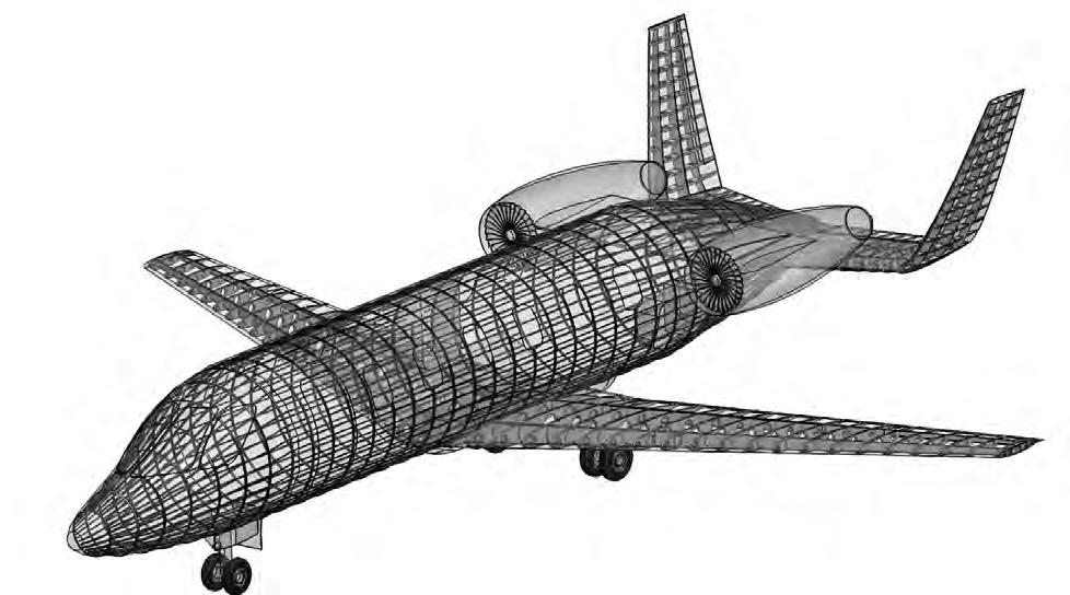
68 12. Structural Analysis 12.1 Material Selection and Integration To begin the material selection process, different types of aluminums will be used throughout the aircraft structure for both the UT-6 and UT-8 variant. Aluminum was chosen because of its high fatigue strength and low weight. Moreover, our aluminum structure will have unlimited life for an unlimited amount of flight hours to have FAA certification(christy) for both the UT-6 and UT-8. To meet the 70% commonality objective both the UT-6 and UT-8 will have a similar structure layout as shown in figure Figure : Preliminary Airframe Structure for Both UT-6 and UT-8 Different aircraft materials were examined for the UT-6 & UT-8. The wing and tail consist of the spars, ribs, and stringers which will be made from aluminum 7075-T73 which has low stress corrosion. Aluminum 7075-T73 has excellent mechanical properties as shown in Table The fuselage structure consists of skins, frames, and stringers which will be made from aluminum 2024-T3. Aluminum 2024-T3 has excellent mechanical properties as shown in Table
69 Table : Mechanical Properties of Aluminum 7075-T73 and 2024-T3 Mechanical Properties Aluminum 7075-T73 Aluminum 2024-T3 Ultimate Tensile Strength (ksi) Compressive Yield Strength (ksi) Modulus of Elasticity (Msi) Shear Modulus (Msi) Fatigue Strength (ksi) The mechanical properties will be used to show how the aircraft structure withstands ultimate load limit, maximum dynamic pressure or max q condition, at RFP cruise altitude 35,000 ft. where margins of safety will be calculated to show the structural integrity of the aircraft. Preliminary Load Calculations 12.2 Preliminary Load Calculations V-n diagrams The structural analysis of the aircraft started with the construction of the V-n Diagram for each variant of the U-tail design at cruise condition and MTOW. Following FAR part (c) and for the 6 passenger variant and FAR part for the 8 passenger variant respectively, the V-n shows both maneuver and gust envelope. FAR (c) was used to calculate design speeds for stall, V S, maneuver, V A, maximum gust intensity, V B, cruise, V C, dive, V D, and were plotted against design load factors all in equivalent airspeed. Maneuver loads factors were calculated using the following equation: From Schaufele pg ,000 n max = MTOW + 10,000 Eqn 12.2 Where the positive load factor only varies with maximum takeoff weight. The negative max load was determined by following FAR (b)(1) of multiplying the positive load factor by 0.4. Similarly, load factors were determined from symmetrical gust factors that vary with equivalent airspeed and were determined using the following equation. From Schaufele pg. 272 n = 1 + K gu ge V E a 498( W S ) Eqn
. Figure 12.2.1-1 shows the UT-6 V-n diagram at 35,000 ft. altitude at Mach 0.85 and with a MTOW of 11,800 lbs.")
70 Where K_g is gust alleviation factor, U_gE is the equivalent gust velocity, W/S is wing loading, V_E is aircraft equivalent airspeed, a is the slope of the airplane normal force curve. All gusts were linearly reduced to cruise altitude as shown in Figure (UT-6 V-n). Figure shows the UT-6 V-n diagram at 35,000 ft. altitude at Mach 0.85 and with a MTOW of 11,800 lbs. in its clean configuration, without flaps or slats deployed. The figures show the V-n for both the UT-6 & UT-8 variant below. UT-6: Mach 0.85 Cruise & 35,000 ft. Cruise Altitude Figure : V-n Diagram Maneuvering & Gust Envelope: UT-6 Following FAR part 25 for the UT-8 the EQUATION was used to calculate maximum maneuvering loads. Similarly, the gust loads were determined using FAR and were reduced linearly to cruise altitude as shown in figure Figure shows the V-n diagram of the UT-8 at 35,000 ft. at Mach 0.85 and with a MTOW of 15,200 lbs. in its clean configuration, without flaps or slats deployed. 61
71 UT-8: Mach 0.85 Cruise & 35,000 ft. Cruise Altitude Figure : V-n Diagram Maneuvering & Gust Envelope: UT-8 Figure shows the UT-6 will experience maximum maneuver loads of 3.2 and Similarly, Figure shows that the UT-8 will experience maximum maneuver loads of 3.05 and Both figures show that the gust loads are not critical because they stay in the maneuver envelope. The maximum loads obtained from the V-n diagrams will used in the structural analysis to make sure our aircraft can withstand max load Wing and Fuselage Shear and Bending Analysis The next step in the structural analysis is shear and bending calculations on both the wing and fuselage. The shear and bending analysis was done at the most critical condition or max dynamic pressure determined by the V-n Diagrams Wing Analysis The wing is treated like a simple cantilever beam fixed at the fuselage/wing connection. The loading on the wing was determined by taking the span wise load distribution obtained from LinAir and combining it with the weight loading of the wing structure, fuel system and landing 62

 500 400 25 20 15 10 5 0 300 200 100 0-100 Load (lbs/ft) Semi-Span (ft) -200 (b) Figure")
72 gear. The net loading distribution on the wing was found and used for the remainder of the calculations. Figure shows the loading distribution of the UT-8 and UT-6 variants. UT-8 Load Distribution (Max q) Load (lbs/ft) -200 Semi-Span (ft) -300 (a) UT-6 Load Distribution (Max q) Load (lbs/ft) Semi-Span (ft) -200 (b) Figure : Wing Load Distribution (a) UT-8 & (b) UT-6 63
73 The shear, moment, deflection angle, and wing tip deflection diagrams were then determined and can be seen in Figure From these plots it is determined that the UT-8 will experience 4,500 lbs of shear force and a moment of 33,500 ft-lbs at the connection between the fuselage and wing. The angle and max deflection at the wing tip were calculated to be 1.2 and 0.51 ft. Similarly, the UT-6 will experience 3,500 lbs, 26,000 ft-lbs, 0.92, and 0.40 ft. respectively. (a) (b) (c) (d) Figure : Analysis at Dive Speed (Max q); level cruise; 35,000 ft.; full fuel condition (a) Shear (b) Moment (c) Deflection Angle (d) Wing Tip Deflection Fuselage Analysis The fuselage analysis was done in a similar manner as the wing, however the fuselage only takes into account maximum weights. The fuselage is treated like a simple cantilever beam fixed at the center of pressure. All loads are distributed along the various sections of the fuselage except the engine which is treated like a point load at the engine CG and accounted for accordingly. Figure shows the loading condition for both UT-8 and UT-6. Only an overlay of the UT-8 is used for visualization. 64

74 Fuselage Weight Load Distribution Load (lbs/ft) UT-8 UT-6 Length (ft) Figure : Fuselage Weight Load Distribution for UT-8 and UT-6 at MTOW The shear and moment diagrams were then determined and can be seen in Figure From the plots the maximum shear force and moment at the center of pressure were determined to be -5,500 lbs and -211,000 ft-lbs for the UT-8 and -4,400 lbs and -143,000 ft-lbs for the UT-6. The discontinuity in the fuselage shear and moment diagrams at the wing center of pressure appears since the wing lift was not included at the point and would be reconciled if added; however, this is a simply evaluation of max fuselage loads forward and aft of the wing and is not necessary to evaluate. (a) 65

75 (b) Figure : Fuselage analysis at MTOW (a) shear (b) moment 12.3 Internal Structure The internal structure was sized based on the max loads from the v-n diagrams and the max moments determined in section 12.1 and 12.2 for the most extreme flight conditions. The wing will have the most critical loads and a factor of safety of 1.5 was applied to meet FAR part 23 and Wing The wing is made up of a front spar, aft spar, stringers, ribs, and skin. The spars are I-beams design with stringers that are of a Z configuration with dimensions seen below. The front spar is placed at 20% wing chord and the aft spar is placed at 77% wing chord with a total of 10 stringers. There are 45 ribs that are placed every 12 inches. The ribs vary with chord length; images below show the type of rib and the ratio in terms of chord length. The wing skin thickness is inches. A complete visualization of the wing internal structure can be seen below. 66

76 The stresses for the wing were determined using the max loads at dive speed. Table shows the max loads, calculated stresses, and margins of safety for a simplified wing box made of 2 I beams. The final stresses showed high margins of safety indicating infinite life. Table : Wing Stress and Margin of Safety Analysis + Load factor - Load Factor + Stress (ksi) - Stress (ksi) + MS - MS UT UT Fuselage and Empennage Structure Similar to the process done for the wing structure, the fuselage is made up of frames and stringers. The stringers used for the wing structure are also used in the fuselage. There is a total of 36 stringers that have a spacing of 5.59 inches. The frames are spaced every 16 inches. The fuselage skin thickness is inches. The empennage was designed in a similar manner with a total of 26 ribs for the vertical tail section combined with 25 ribs for the horizontal tail section, 23 stringers, and three spars located at 20%, 24%, and 50% tail chord. The skin thickness is inches. A complete visualization of the whole interior structure can be seen below. 67
77 68

78 13. Subsystems As a preliminary analysis, several subsystems were included in the design to show a basic layout of these components. These subsystems include: fuel tanks, electrical wiring, hydraulics, cabin pressurization and air conditioning, and cabin fire protection. All these subsystems were analyzed with the FAR requirements to ensure the comfort and safety of the aircraft and the passengers Fuel To satisfy the range requirement of 2,500 nmi and the 100 nmi of NBAA alternative, our team had to calculate the necessary amount of fuel to complete the mission profile. The fuel requirements were calculated using the Breguet Range equations with the assumption that the aircraft will utilize Jet A-1 fuel. UT-8 will require 718 gallons of fuel and a fuel tank that has a volume of at least 96 cubic feet. UT-6 will require 561 gallons of fuel and a fuel tank that has a volume of at least 75 cubic feet. Table shows the fuel requiems for both aircraft. Fuel Required Volume In Each Tank UT Gallons 48 cubic feet UT Gallons 37.5 cubic feet Table Required Fuel Volume for Each Aircraft Two fuel tanks will be placed in the wing between the two main spars, one will be on the left side of the wing and one will be placed on the right side of the wing Figure illustrates a top view of where the fuel tanks will go and Figure illustrates an isometric view; with the purple area on the wing representing the fuel tanks. Tank 1 Tank 2 Figure Top view of the Fuel Tanks Integrated on the Wing 69


79 Tank 2 Tank 1 Figure Isometric view of the Fuel Tanks Integrated on the Wing Each fuel tank for the UT-8 aircraft will have a volume of 48 cubic feet and each fuel tank for UT-6 aircraft will have a volume of 37.5 cubic feet. The fuel tanks will be baffled to prevent sloshing as the fuel is used up during flight. During flight the left fuel tank will supply the left engine and the right fuel tank will supply the right engine, and a crossflow valve will be integrated onto the fuel system so that fuel from both tanks can supply any engine in case of an emergency. Figure shows the fuel valve system. Figure Fuel Valve System of the Aircraft 70
80 13.2 Electrical The electrical subsystem consists of batteries, generators, electric controls, circuit breakers, and cables. As seen in Figure , the APU is installed near the engines, to provide ground power for air conditioning, cabin lighting, and engine starting. Further information regarding the APU is provided in section Generators Figure UT-6 and UT-8 Electrical Subsystem Layout 13.3 Hydraulic The hydraulic subsystem supplies pressure to control the landing gears, doors, control surfaces, and brakes. The system is split into two sides, left and right. For each side, there is a pump, reservoir, and series of actuators. The pumps are connected to the engines and the third one is connected to the APU. Each pump is capable of pressurizing the complete hydraulic system. The two forward reservoirs are responsible for the actuators on the side of the aircraft as well as the landing gears. The aft reservoir supplies the actuators of the tail control surfaces and the cargo door. All three reservoirs are connected to each other in case of a failure. Figure shows the mechanisms and connections of the hydraulic subsystem. The hydraulic subsystem meets the FAR for the UT-6 and FAR for the UT-8. 71

81 Figure : Hydraulic Subsystem for the UT APU Auxiliary power units are used to keep electrical and air conditioning systems running without having to keep engines running while on the ground, additionally they can be used to start the engines. In order to select an APU, other similar aircraft in the same thrust class were researched. The selected APU is the RE100 from Honeywell. The RE100 weighs 79 lbs and produces 17 shp which is capable of starting the TFE engines on a Learjet
82 13.5 Water and Waste Subsystem In both the UT-6 and the UT-8, the galley is equipped with a water drain system. This is connected to the drain system of the sink in the aft lavatory. The water drain systems in the business jet are connected to the vacuum waste system that makes up the toilet. The vacuum system minimizes the power consumption and reduces maintenance requirements. The toilet is also equipped with an in-built macerator to break down the waste. The waste is flushed through a waste dump line. The water and toilet waste is stored in a reservoir with 4-gallon waste capacity in the lower right aft section of both the UT-6 and the UT-8 business jets. These are then serviced externally, through a service panel connected to the reservoir. The water and waste drainage systems are seen in Figure below. Galley Water Drain System Aft Lavatory Sink Waste Reservoir Waste Dump Line Figure Water and Waste Subsystem for the UT Cabin Pressurization and Air conditioning The aircraft cabin is both pressurized and air conditioned to add comfort for the flight crew and passengers, while traveling 5-6 hours in flight. To comply with the FAR requirement and FAR , the cabin altitude will be held at 8,000 ft. at the maximum cruise altitude of 35,000 ft. In the incident of an unplanned decompression, 73
83 oxygen masks will be deployed automatically in the cockpit and in the cabin. It will be dropped down automatically from the top of the cabin, to the passenger s face. Bleed air from the turbofan engines is used to pressurize the cabin and air is released from the cabin by an outflow valve located at the bottom of the fuselage towards the end. To control the interior pressure, and allow old, nasty air to exit, the pilot can control the outflow valve to release it. A condenser unit will convert the hot bleed air into cold, allowing air conditioning in the cabin. Figure shows the system of the cabin pressurization and air conditioning. Figure : Cabin Pressurization and Air Conditioning Subsystem 13.7 Cabin Fire Detection and Extinguisher Systems To protect the aircraft in the case of fire emergency, the UT-6 would need to meet the FAR 23 sections 851 through 865 requirements and the UT-8 would need to meet the FAR 25 sections 851 through 869 requirements. There will be six smoke detectors: one in the cockpit, four in the passenger cabin, and one in the cargo. Light-refraction type smoke detectors were selected over the ionization type so they will remain independent of the aircraft electric power, in the case of power-off due to a fire. The smoke detector system will provide a light in the cockpit in case of a fire. In addition, there will be three portable fire extinguishers: one in the cockpit and two in the passenger cabin. 74
84 Each extinguisher is designed to minimize the hazard of toxic gas concentrations. Figure shows the fire protection system of the UT design. Figure : Fire Protection System for UT design 75

85 14. Manufacturing Process The manufacturing process of both variants of the aircraft will be completed in a conventional assembly line style using a 6-step main sub-assembly process. The large similarities between the UT-8 and UT-6 will enable the manufacturing process to be faster and more efficient due to the higher amount of parts and sub-systems that will be the same between the two airplanes. A plug of 5ft will be added to the fuselage of the UT-8 to accommodate two extra passengers % Commonality One of the design objectives was to have a 70% commonalty between the UT-8 and the UT-6, based on the empty weight of the aircraft, and excluding the engines. The empty weight of the UT-8 is 8,628 pounds and the empty weight for the UT-6 is 5,911 pounds, and each airplane has a combined engine weight of 1,396 pounds. This means that based on the criteria mentions above, there is an 86% commonality between each aircraft. The airplanes not only met the 70% commonality objective, but they surpassed it by 16%. Some of the main factors that contributed to high commonality include the fact that the wing, tail, engines and landing gear are the same for both the UT-8 and the UT-6. The width of the fuselage is also the same, with the main difference between the fuselage s being that the fuselage for the UT-6 is five feet shorter than the fuselage for the UT-8. Having a higher commonality between each aircraft will significantly cut down the cost and time of manufacturing because certain components of the aircraft can be manufactured for both variants. Figure show the UT-8 and the UT-6, and how similar they look next to each other. Figure On the left is the UT-6 and on the right is the Ut-8 76


86 14.2 Manufacturing Process Since both variants of the aircraft have such a high commonality, the UT-8 and the UT-6 will be manufactured side by side on a conventional aircraft assembly line. The manufacturing process will consist of six main subassemblies. Diagram shows these main subassemblies. 1. Fuselage Assembly Including the structure, nose, cabin, tail cone. 2. Empennage The U-tail will be assembled here. This included the rudders, horizontal stabilizer, and structure. 4. Landing Gear The tricycle style landing gear will be incorporated onto the fuselage. 3. Wing Assembly This included the fuel systems, ribs, spars, ailerons and flaps. 5. Electronic sub-systems This included the APU and the flight control systems. 6. Powerplant The engines will be the last component assembled. Diagram Flow Chart of the Manufacturing Process The manufacturing process will start with the fuselage which includes the nose section and the stringers and frames that make up the structural skeleton. The next large subassembly is the empennage section where the U-tail will be integrated with the fuselage. Next is the wing assembly which will have the fuel systems and structural components 77

87 already integrated. The landing gear will then be incorporated onto the fuselage. The APU and all the flight control systems and electrical systems will be assembled onto the aircraft, and finally the engines will be attached to the fuselage. Figure is a representation of the major structural components of the UT-8 aircraft after full assembly of all the aircraft components. Figure : Structure Component of the UT-8 aircraft 78

.")
88 15. Program Lifecycle The program lifecycle outlines the major milestone for the UT-6 and UT-8 designs. The program approval is set for June, One year after the approval, 4 aircraft will be built for development, analysis, and testing, following the certification. By 2020, the UT-6 will be certified and ready for Entry into Service and by 2022 the UT-8 will be ready. After flying the aircraft for years, the disposal process will be managed through a third party company called Aircraft Fleet Recycling Association (AFRA). AFRA will incorporate new technologies and disposal methods to make the disassembling process more environmentally friendly. Figure 15-1: Program Lifecycle 79

89 16. Cost Analysis One of the important objectives mentioned in the RFP is to minimize flyaway cost and direct operating cost. According to the RFP, the entry into service date for the UT-6 is 2020 and the UT-8 is The cost analysis was done in 2020 USD and 2022 USD for the respective aircraft therefore, all the values used for the cost analysis were inflated to 2020 USD and 2022 USD using: (Inflated Year Current Year) X inflated = X current Two methods were used to calculate the cost analysis: Nicolai & Carichner (N&C) method and Raymer method Research, Development, Test and Evaluation By using N&C s method, the RDT&E cost was calculated to be $435 million for the UT-6 and $585 million for the UT-8. Using Raymer s method, the RDT&E cost was calculated to be $470 million for the UT-6 and $645 million for the UT-8. The RDT&E cost breakdown are shown below in Figure through Figure , showing the two methods used for each aircraft. These cost breakdowns shows the calculated values based on the MTOW, maximum speed, and a total of 2 aircraft produced for testing and analysis. Figure : RDT&E Cost Breakdown for UT-6 using Nicolai & Carichner s method. 80
90 Figure : RDT&E Cost Breakdown for UT-6 using Raymer s method. Figure : RDT&E Cost Breakdown for UT-8 using Nicolai & Carichner s method. 81
91 Figure : RDT&E Cost Breakdown for UT-8 using Raymer s method Production Costs The production costs for the UT-6 and UT-* were calculated using the same methods used in the previous section. For both variants, 250 aircraft were produced. Table shows the different methods used and the cost breakdown for the production cost, which is also based on the MTOW, maximum speed, and the number of aircraft to be produced. The costs for the engines and the avionics were estimated by using Nicolai & Carichner s method for all four methods. Just to note, the RDT&E costs are not included in the total production costs. 82


92 Table : Production Cost Breakdown for the UT-6 and UT-8 Using Both Methods Flyaway Cost The flyaway cost was calculated by dividing the total production cos by the number of aircraft produced. Table shows the flyaway cost used for each method as well as a profit margin of 10%, which is the selling price of the aircraft. Table : Flyaway Cost and Selling Price of UT-6 and UT-8 The flyaway cost of the UT family of business jets was compared to aircraft that are in their weight and seating capacity category. The selling price of the already existing jets were obtained from the BC&A Equipped Price list from 2015 and were inflated to the corresponding EIS date and were assumed to have a 10% profit margin. It is evident that both variants are slightly more expensive their competitors in this 83


93 case. However, both the UT variants exhibit a more spacious cabin and better performance capability, as expressed in earlier sections. Table : Selling Price Comparisons with UT-6 Table : Flyaway Cost Comparisons with UT Break Even Point The break-even point for the aircraft using the two different methods are shown in Figure through Figure JetBiz predicts to sell 250 UT-6 aircraft and 250 UT-8 aircraft in a span of 10 years. This means the company would need to sell about 4 aircraft a month to stay competitive with the Embraer Phenom
94 Figure : Production Break-Even Point for UT-6 Using Nicolai & Carichner s Method. Figure : Production Break-Even Point for UT-6 Using Raymer s Method. 85
95 Figure : Production Break-Even Point for UT-8 Using Nicolai & Carichner s Method. Figure : Production Break-Even Point for UT-8 Using Raymer s Method. 86

96 16.5 Direct Operating and Maintenance Cost The D.O.C was calculated using equations in N&C text. The calculation was based on the MTOW, number of crew, maximum range, and the net thrust of the engine at standard sea level. Fuel is the major cost driver on the operating cost for the UT-6 and UT-8. The operational cost per flight hour for the UT-6 was calculated to be $10,192 and for the UT-8, $12,331. Figure and Figure shows the operating cost breakdown for the UT designs. In addition, the fuel cost per nautical mile was calculated and compared to similar business jets in the market, shown in Table Figure : Direct Operating Cost Breakdown for UT-6 87


97 Figure : Direct Operating Cost Breakdown for UT-8 The fuel cost per nautical mile in the UT-6 is seen to be 29% lower than that of its main competitor, Syberjet s SJ30 while the UT-8 is 130% cheaper than the Embraer Phenom 300. This shows that despite the slighter higher flyaway cost, and in turn, unit cost, of both of the UT jets, are less expensive to operate. Table : Fuel Efficiency Comparison of UT Designs and Similar Aircraft 88
The Airplane That Could!
 The Airplane That Could! Critical Design Review December 6 th, 2008 Haoyun Fu Suzanne Lessack Andrew McArthur Nicholas Rooney Jin Yan Yang Yang Agenda Criteria Preliminary Designs Down Selection Features
AIRCRAFT DESIGN SUBSONIC JET TRANSPORT
 AIRCRAFT DESIGN SUBSONIC JET TRANSPORT Analyzed by: Jin Mok Professor: Dr. R.H. Liebeck Date: June 6, 2014 1 Abstract The purpose of this report is to design the results of a given specification and to
AE 451 Aeronautical Engineering Design Final Examination. Instructor: Prof. Dr. Serkan ÖZGEN Date:
 Instructor: Prof. Dr. Serkan ÖZGEN Date: 11.01.2012 1. a) (8 pts) In what aspects an instantaneous turn performance is different from sustained turn? b) (8 pts) A low wing loading will always increase
Aircraft Design in a Nutshell
 Dieter Scholz Aircraft Design in a Nutshell Based on the Aircraft Design Lecture Notes 1 Introduction The task of aircraft design in the practical sense is to supply the "geometrical description of a new
Aircraft Design Conceptual Design
 Université de Liège Département d Aérospatiale et de Mécanique Aircraft Design Conceptual Design Ludovic Noels Computational & Multiscale Mechanics of Materials CM3 http://www.ltas-cm3.ulg.ac.be/ Chemin
TEAM Four Critical Design Review. Kai Jian Cheong Richard B. Choroszucha* Lynn Lau Mathew Marcucci Jasmine Sadler Sapan Shah Chongyu Brian Wang
 TEAM Four Critical Design Review Kai Jian Cheong Richard B. Choroszucha* Lynn Lau Mathew Marcucci Jasmine Sadler Sapan Shah Chongyu Brian Wang 03.XII.2008 0.1 Abstract The purpose of this report is to
Flugzeugentwurf / Aircraft Design SS Part 35 points, 70 minutes, closed books. Prof. Dr.-Ing. Dieter Scholz, MSME. Date:
 DEPARTMENT FAHRZEUGTECHNIK UND FLUGZEUGBAU Flugzeugentwurf / Aircraft Design SS 2015 Duration of examination: 180 minutes Last Name: Matrikelnummer: First Name: Prof. Dr.-Ing. Dieter Scholz, MSME Date:
Team 2. AAE451 System Requirements Review. Chad Carmack Aaron Martin Ryan Mayer Jake Schaefer Abhi Murty Shane Mooney
 Team 2 AAE451 System Requirements Review Chad Carmack Aaron Martin Ryan Mayer Jake Schaefer Abhi Murty Shane Mooney Ben Goldman Russell Hammer Donnie Goepper Phil Mazurek John Tegah Chris Simpson Outline
AIRCRAFT DESIGN MADE EASY. Basic Choices and Weights. By Chris Heintz
 AIRCRAFT DESIGN MADE EASY By Chris Heintz The following article, which is a first installement of a two-part article, describes a simple method for the preliminary design of an airplane of conventional
Chapter 10 Miscellaneous topics - 2 Lecture 39 Topics
 Chapter 10 Miscellaneous topics - 2 Lecture 39 Topics 10.3 Presentation of results 10.3.1 Presentation of results of a student project 10.3.2 A typical brochure 10.3 Presentation of results At the end
Systems Group (Summer 2012) 4 th Year (B.Eng) Aerospace Engineering Candidate Carleton University, Ottawa,Canada Mail:
 4 th Year (B.Eng) Aerospace Engineering Candidate Carleton University, Ottawa,Canada Mail:") Memo Airport2030_M_Family_Concepts_of_Box_Wing_12-08-10.pdf Date: 12-08-10 From: Sameer Ahmed Intern at Aero Aircraft Design and Systems Group (Summer 2012) 4 th Year (B.Eng) Aerospace Engineering Candidate
Memo Airport2030_M_Family_Concepts_of_Box_Wing_12-08-10.pdf Date: 12-08-10 From: Sameer Ahmed Intern at Aero Aircraft Design and Systems Group (Summer 2012) 4 th Year (B.Eng) Aerospace Engineering Candidate
AE 451 Aeronautical Engineering Design I Estimation of Critical Performance Parameters. Prof. Dr. Serkan Özgen Dept. Aerospace Engineering Fall 2015
 AE 451 Aeronautical Engineering Design I Estimation of Critical Performance Parameters Prof. Dr. Serkan Özgen Dept. Aerospace Engineering Fall 2015 Airfoil selection The airfoil effects the cruise speed,
The Sonic Cruiser A Concept Analysis
 International Symposium "Aviation Technologies of the XXI Century: New Aircraft Concepts and Flight Simulation", 7-8 May 2002 Aviation Salon ILA-2002, Berlin The Sonic Cruiser A Concept Analysis Dr. Martin
TYPE-CERTIFICATE DATA SHEET
 TYPE-CERTIFICATE DATA SHEET NO. EASA.IM.A.073 for Beechcraft 390 (PREMIER I and IA) Type Certificate Holder: Textron Aviation Inc. One Cessna Boulevard Wichita, Kansas 67215 USA For Models: Model 390 1
Design Considerations for Stability: Civil Aircraft
 Design Considerations for Stability: Civil Aircraft From the discussion on aircraft behavior in a small disturbance, it is clear that both aircraft geometry and mass distribution are important in the design
EAS 4700 Aerospace Design 1
 EAS 4700 Aerospace Design 1 Prof. P.M. Sforza University of Florida Commercial Airplane Design 1 1.Mission specification and market survey Number of passengers: classes of service Range: domestic or international
Appenidix E: Freewing MAE UAV analysis
 Appenidix E: Freewing MAE UAV analysis The vehicle summary is presented in the form of plots and descriptive text. Two alternative mission altitudes were analyzed and both meet the desired mission duration.
2008/2009 AIAA Undergraduate Team Aircraft Design
 2008/2009 AIAA Undergraduate Team Aircraft Design 2 3 Executive Summary Fusion Aeronautics presents the HB-86 Navigator as a solution to the 2008-2009 AIAA Undergraduate Aircraft Design Competition RFP.
Environautics EN-1. Aircraft Design Competition. Presented by Virginia Polytechnic Institute and State University
 Environautics EN-1 Response to the 2009-2010 AIAA Foundation Undergraduate Team Aircraft Design Competition Presented by Virginia Polytechnic Institute and State University Left to Right: Justin Cox, Julien
Multidisciplinary Design Optimization of a Truss-Braced Wing Aircraft with Tip-Mounted Engines
 Multidisciplinary Design Optimization of a Truss-Braced Wing Aircraft with Tip-Mounted Engines NASA Design MAD Center Advisory Board Meeting, November 14, 1997 Students: J.M. Grasmeyer, A. Naghshineh-Pour,
Ember Aviation LAT-1
 Ember Aviation Presents the LAT-1 In response to the 2015 2016 AIAA Foundation Undergraduate Team Aircraft Design Competition Presented by California Polytechnic State University, Pomona Aerospace Engineering
Multidisciplinary Design Optimization of a Strut-Braced Wing Transonic Transport
 Multidisciplinary Design Optimization of a Strut-Braced Wing Transonic Transport John F. Gundlach IV Masters Thesis Defense June 7,1999 Acknowledgements NASA LMAS Student Members Joel Grasmeyer Phillipe-Andre
Final Proposal AIAA Undergraduate Design Competition
 Final Proposal 2008-2009 AIAA Undergraduate Design Competition Submitted: June, 2009 Page 2 Greenspan Preliminary Design Team Jason Riopelle Scott Buttrill David M. Cross Team Leader and Noise Stability
Classical Aircraft Sizing I
 Classical Aircraft Sizing I W. H. Mason from Sandusky, Northrop slide 1 Which is 1 st? You need to have a concept in mind to start The concept will be reflected in the sizing by the choice of a few key
Initech Aircraft is proud to present the JTC-2 E Swingliner in response to the
 ii Executive Summary Initech Aircraft is proud to present the JTC-2 E Swingliner in response to the 2006-2007 AIAA undergraduate design competition. The Swingliner has been developed as a survivable transport
Aircraft Design: A Systems Engineering Approach, M. Sadraey, Wiley, 2012 Chapter 11 Aircraft Weight Distribution Tables
 Aircraft Design: A Systems Engineering Approach, M. Sadraey, Wiley, 01 Chapter 11 Aircraft Weight Distribution Tables No Component group Elements Weight X cg Y cg Z cg 1 Wing 1.1. Wing main structure 1..
ECO-CARGO AIRCRAFT. ISSN: International Journal of Science, Engineering and Technology Research (IJSETR) Volume 1, Issue 2, August 2012
 Volume 1, Issue 2, August 2012") ECO-CARGO AIRCRAFT Vikrant Goyal, Pankhuri Arora Abstract- The evolution in aircraft industry has brought to us many new aircraft designs. Each and every new design is a step towards a greener tomorrow.
ECO-CARGO AIRCRAFT Vikrant Goyal, Pankhuri Arora Abstract- The evolution in aircraft industry has brought to us many new aircraft designs. Each and every new design is a step towards a greener tomorrow.
AIAA Foundation Undergraduate Team Aircraft Design Competition. RFP: Cruise Missile Carrier
 AIAA Foundation Undergraduate Team Aircraft Design Competition RFP: Cruise Missile Carrier 1999/2000 AIAA FOUNDATION Undergraduate Team Aircraft Design Competition I. RULES 1. All groups of three to ten
Environmentally Focused Aircraft: Regional Aircraft Study
 Environmentally Focused Aircraft: Regional Aircraft Study Sid Banerjee Advanced Design Product Development Engineering, Aerospace Bombardier International Workshop on Aviation and Climate Change May 18-20,
TEAM AEROHEAD AERONAUTICS
 Presents AA SB-01 Response to 2008/2009 AIAA Foundation Undergraduate Team Aircraft Design Competition Presented by Virginia Polytechnic Institute and State University TEAM AEROHEAD AERONAUTICS From left
AeroTactic Company. FF-1 Rainbird
 AeroTactic Company presents the FF-1 Rainbird In response to the 2015-2016 AIAA Foundation Graduate Team Aircraft Design Competition Presented by California State Polytechnic University, Pomona Aerospace
Performance means how fast will it go? How fast will it climb? How quickly it will take-off and land? How far it will go?
 Performance Concepts Speaker: Randall L. Brookhiser Performance means how fast will it go? How fast will it climb? How quickly it will take-off and land? How far it will go? Let s start with the phase
Chapter 2 Lecture 5 Data collection and preliminary three-view drawing - 2 Topic
 Chapter 2 Lecture 5 Data collection and preliminary three-view dra - 2 Topic 2.3 Preliminary three-view dra Example 2.1 2.3 Preliminary three-view dra The preliminary three-view dra of the airplane gives
Chapter 10 Parametric Studies
 Chapter 10 Parametric Studies 10.1. Introduction The emergence of the next-generation high-capacity commercial transports [51 and 52] provides an excellent opportunity to demonstrate the capability of
European Aviation Safety Agency
 Page 1/8 European Aviation Safety Agency EASA TYPE CERTIFICATE DATA SHEET Cirrus Design SF50 Type Certificate Holder: Cirrus Design Corporation 4515 Taylor Circle Duluth, Minnesota 55811 United States
A Game of Two: Airbus vs Boeing. The Big Guys. by Valerio Viti. Valerio Viti, AOE4984, Project #1, March 22nd, 2001
 A Game of Two: Airbus vs Boeing The Big Guys by Valerio Viti 1 Why do we Need More Airliners in the Next 20 Years? Both Boeing and Airbus agree that civil air transport will keep increasing at a steady
Karpuk Aircraft KR-1 Multi-Mission Amphibian
 Karpuk Aircraft KR-1 Multi-Mission Amphibian Response to 2016/2017 AIAA Foundation Graduate Individual Aircraft Design Competition Presented by Embry-Riddle Aeronautical University (Daytona Beach) Department
INDIAN INSTITUTE OF TECHNOLOGY KANPUR
 INDIAN INSTITUTE OF TECHNOLOGY KANPUR INDIAN INSTITUTE OF TECHNOLOGY KANPUR Removable, Low Noise, High Speed Tip Shape Tractor Configuration, Cant angle, Low Maintainence Hingelesss, Good Manoeuverability,
AIAA UNDERGRADUATE TEAM DESIGN COMPETITION PROPOSAL 2017
 TADPOLE AIAA UNDERGRADUATE TEAM DESIGN COMPETITION PROPOSAL 2017 Conceptual Design of TADPOLE Multi-Mission Amphibian MIDDLE EAST TECHNICAL UNIVERSITY 5-10-2017 Team Member AIAA Number Contact Details
General Dynamics F-16 Fighting Falcon
 General Dynamics F-16 Fighting Falcon http://www.globalsecurity.org/military/systems/aircraft/images/f-16c-19990601-f-0073c-007.jpg Adam Entsminger David Gallagher Will Graf AOE 4124 4/21/04 1 Outline
Hawker Beechcraft Corporation on March 26, 2007
 DEPARTMENT OF TRANSPORTATION FEDERAL AVIATION ADMINISTRATION A00010WI Revision 8 Hawker Beechcraft 390 March 26, 2007 TYPE CERTIFICATE DATA SHEET NO. A00010WI This data sheet, which is part of Type Certificate
AN ADVANCED COUNTER-ROTATING DISK WING AIRCRAFT CONCEPT Program Update. Presented to NIAC By Carl Grant November 9th, 1999
 AN ADVANCED COUNTER-ROTATING DISK WING AIRCRAFT CONCEPT Program Update Presented to NIAC By Carl Grant November 9th, 1999 DIVERSITECH, INC. Phone: (513) 772-4447 Fax: (513) 772-4476 email: carl.grant@diversitechinc.com
Flugzeugentwurf / Aircraft Design WS 10/ Klausurteil 30 Punkte, 60 Minuten, ohne Unterlagen. Prof. Dr.-Ing. Dieter Scholz, MSME
 DEPARTMENT FAHRZEUGTECHNIK UND FLUGZEUGBAU Prof. Dr.-Ing. Dieter Scholz, MSME Flugzeugentwurf / Aircraft Design WS 10/11 Bearbeitungszeit: 180 Minuten Name: Matrikelnummer.: Vorname: Punkte: von 68 Note:
AIAA Foundation Student Design Competition 2015/16. Undergraduate Individual Aircraft
 AIAA Foundation Student Design Competition 2015/16 Undergraduate Individual Aircraft Conceptual Design of TAJ PEGASUS A Long Range Container Transportation Aircraft Designer & Author : Waheedullah Taj
AAE 451 Conceptual Design Review
 AAE 451 Conceptual Design Review May 6, 2010 Team 1 Alex Mondal Beth Grilliot Brien Piersol Heath Cheung Jason Liu Jeff Cohen Jeremy Wightman Kit Fransen Lauren Hansen Nick Walls Ryan Foley Tim Fechner
TYPE-CERTIFICATE DATA SHEET
 TCDS No.:EASA.IM.A.013 Gulfstream 200 / Galaxy Issue: 03 Date: 03 July 2017 TYPE-CERTIFICATE DATA SHEET EASA.IM.A.013 for GULFSTREAM 200 / GALAXY Type Certificate Holder GULFSTREAM AEROSPACE LP (GALP P.O.
DEVELOPMENT OF A CARGO AIRCRAFT, AN OVERVIEW OF THE PRELIMINARY AERODYNAMIC DESIGN PHASE
 ICAS 2000 CONGRESS DEVELOPMENT OF A CARGO AIRCRAFT, AN OVERVIEW OF THE PRELIMINARY AERODYNAMIC DESIGN PHASE S. Tsach, S. Bauminger, M. Levin, D. Penn and T. Rubin Engineering center Israel Aircraft Industries
Cessna Citation Model Stats
 Cessna Citation Model Stats Cessna Citation Sovereign - Dimensions Length 63 ft 6 in (19.35 m) Height 20 ft 4 in (6.20 m) Wingspan 72 ft 4 in (22.04 m) Wing Wing Area Wing Sweep Wheelbase Tread 516 sq
AIAA Undergraduate Team Aircraft Design
 Homeland Defense Interceptor (HDI) 2005 2006 AIAA Undergraduate Team Aircraft Design Group Members and Responsibilities Name Discipline AIAA Number John Borgie Configuration and Systems 268357 Ron Cook
Aeronautical Engineering Design II Sizing Matrix and Carpet Plots. Prof. Dr. Serkan Özgen Dept. Aerospace Engineering Spring 2014
 Aeronautical Engineering Design II Sizing Matrix and Carpet Plots Prof. Dr. Serkan Özgen Dept. Aerospace Engineering Spring 2014 Empty weight estimation and refined sizing Empty weight of the airplane
DESIGN OF A FIFTH GENERATION AIR SUPERIORITY FIGHTER AIRCRAFT
 Proceedings of the International Conference on Mechanical Engineering and Renewable Energy 2015 (ICMERE2015) 26 29 November, 2015, Chittagong, Bangladesh ICMERE2015PI152 DESIGN OF A FIFTH GENERATION AIR
CONCEPTUAL DESIGN OF ECOLOGICAL AIRCRAFT FOR COMMUTER AIR TRANSPORTATION
 26 TH INTERNATIONAL CONGRESS OF THE AERONAUTICAL SCIENCES CONCEPTUAL DESIGN OF ECOLOGICAL AIRCRAFT FOR COMMUTER AIR TRANSPORTATION Yasuhiro TANI, Tomoe YAYAMA, Jun-Ichiro HASHIMOTO and Shigeru ASO Department
CONCEPTUAL DESIGN AND AERODYNAMIC STUDY OF JOINED-WING BUSINESS JET AIRCRAFT
 28 TH INTERNATIONAL CONGRESS OF THE AERONAUTICAL SCIENCES CONCEPTUAL DESIGN AND AERODYNAMIC STUDY Kim Ern Foong* and Harijono Djojodihardjo** Universiti Putra Malaysia *Graduate, **Professor, and corresponding
This Flight Planning Guide is published for the purpose of providing specific information for evaluating the performance of the Cessna Corvalis TT.
 May 2010 TABLE OF CONTENTS This Flight Planning Guide is published for the purpose of providing specific information for evaluating the performance of the Cessna Corvalis TT. This guide is developed from
Classical Aircraft Sizing II
 Classical Aircraft Sizing II W. H. Mason Advanced Concepts from NASA TM-1998-207644 slide 1 11/18/08 Previously (Sizing I) Mission definition Basic Sizing to Estimate TOGW Examples Now: More Details and
Optimum Seat Abreast Configuration for an Regional Jet
 7 th european conference for aeronautics and space sciences (eucass) Optimum Seat Abreast Configuration for an Regional Jet I. A. Accordi* and A. A.de Paula** *Instituto Tecnológico de Aeronáutica São
The Peregrine AEROSPACE ENGINEERING. 2003/2004 AIAA Undergraduate Team Aircraft Design Competition. -an E/STOL, Airport Adaptive Regional Jet-
 The Peregrine AEROSPACE ENGINEERING 2003/2004 AIAA Undergraduate Team Aircraft Design Competition -an E/STOL, Airport Adaptive Regional Jet- Designed by Team ASCENT i The Peregrine -an E/STOL, Airport
CONCEPTUAL DESIGN REPORT
 CONCEPTUAL DESIGN REPORT Agricultural Unmanned Aircraft System (AUAS) Team Two-CAN Team Member Albert Lee (Team Leader) Chris Cirone Kevin Huckshold Adam Kuester Jake Niehus Michael Scott Area of Responsibility
INVESTIGATION OF ICING EFFECTS ON AERODYNAMIC CHARACTERISTICS OF AIRCRAFT AT TSAGI
 INVESTIGATION OF ICING EFFECTS ON AERODYNAMIC CHARACTERISTICS OF AIRCRAFT AT TSAGI Andreev G.T., Bogatyrev V.V. Central AeroHydrodynamic Institute (TsAGI) Abstract Investigation of icing effects on aerodynamic
Preliminary Detailed Design Review
 Preliminary Detailed Design Review Project Review Project Status Timekeeping and Setback Management Manufacturing techniques Drawing formats Design Features Phase Objectives Task Assignment Justification
10th Australian International Aerospace Congress
 AUSTRALIAN INTERNATIONAL AEROSPACE CONGRESS Paper presented at the 10th Australian International Aerospace Congress incorporating the 14th National Space Engineering Symposium 2003 29 July 1 August 2003
Three major types of airplane designs are 1. Conceptual design 2. Preliminary design 3. Detailed design
 1. Introduction 1.1 Overview: Three major types of airplane designs are 1. Conceptual design 2. Preliminary design 3. Detailed design 1. Conceptual design: It depends on what are the major factors for
blended wing body aircraft for the
 Feasibility study of a nuclear powered blended wing body aircraft for the Cruiser/Feeder eede concept cept G. La Rocca - TU Delft 11 th European Workshop on M. Li - TU Delft Aircraft Design Education Linköping,
Small Fixed Wing Aircraft Operational Weight and Balance Computations
 Small Fixed Wing Aircraft Operational Weight and Balance Computations Chapter 4 Weight and balance data allows the pilot to determine the loaded weight of the aircraft and determine whether or not the
CITATION CJ1 (CE-525) ASKING PRICE: US$ 1,095,000
 ASKING PRICE: US$ 1,095,000") CITATION CJ1 (CE-525) ASKING PRICE: US$ 1,095,000 YOM 2003 MSN 525-0517 The CJ1 is the second generation of the extremely successful Citation Jet series. It comes with all of the advantages that the original
CITATION CJ1 (CE-525) ASKING PRICE: US$ 1,095,000 YOM 2003 MSN 525-0517 The CJ1 is the second generation of the extremely successful Citation Jet series. It comes with all of the advantages that the original
European Aviation Safety Agency
 TCDS No.: EASA.IM.A.212 Learjet M60 Page 1 of 15 European Aviation Safety Agency EASA TYPE CERTIFICATE DATA SHEET No. EASA.IM.A.212 for LEARJET Model 60 Type Certificate Holder: Learjet Inc. One Learjet
Flying Low and Slow. (and the Tools for its Calculation) Dieter Scholz. Hamburg University of Applied Sciences
 Dieter Scholz. Hamburg University of Applied Sciences") AIRCRAFT DESIGN AND SYSTEMS GROUP (AERO) (and the Tools for its Calculation) Hamburg University of Applied Sciences 12th European Workshop on Aircraft Design Education (EWADE) 2015 (and the Tools for its
AIRCRAFT DESIGN AND SYSTEMS GROUP (AERO) (and the Tools for its Calculation) Hamburg University of Applied Sciences 12th European Workshop on Aircraft Design Education (EWADE) 2015 (and the Tools for its
TYPE-CERTIFICATE DATA SHEET
 TCDS No.: EASA.IM.A.207 Issue: 04 Date: 28 August 2018 TYPE-CERTIFICATE DATA SHEET No. EASA.IM.A.207 for CESSNA 500, 550, S550, 560, 560XL Type Certificate Holder: Textron Aviation Inc. One Cessna Boulevard
Conceptual Design of a Next Generation, 150 Passenger Commercial Transport
 California Polytechnic State University, San Luis Obispo From the SelectedWorks of Robert A. McDonald January 4, 2010 Conceptual Design of a Next Generation, 150 Passenger Commercial Transport Ryan Halper,
Wing Cuff Design for Cessna CJ1
 Wing Cuff Design for Cessna CJ1 AAE 415 Project Purdue University Saturday, December 10th, 2004 Brian Adams Kevin Clark Greg Davidson Phil Spindler Contents Background of Problem Literature Review Design
Uncontrolled copy not subject to amendment. Airframes. Revision 1.00
 Uncontrolled copy not subject to amendment Airframes Revision 1.00 Chapter 4: Fuselage Learning Objectives The purpose of this chapter is to discuss in more detail the first of the 4 major components
7. PRELIMINARY DESIGN OF A SINGLE AISLE MEDIUM RANGE AIRCRAFT
 7. PRELIMINARY DESIGN OF A SINGLE AISLE MEDIUM RANGE AIRCRAFT Students: R.M. Bosma, T. Desmet, I.D. Dountchev, S. Halim, M. Janssen, A.G. Nammensma, M.F.A.L.M. Rommens, P.J.W. Saat, G. van der Wolf Project
PERFORMANCE ANALYSIS OF UNMANNED AIR VEHICLE INTERCEPTOR (UAV-Ip)
") TH INTERNATIONAL CONGRESS OF THE AERONAUTICAL SCIENCES PERFORMANCE ANALYSIS OF UNMANNED AIR VEHICLE INTERCEPTOR (UAV-Ip) FLT LT MUHAMMAD ASIM AHQ CHAKLALA (PROJ VISION) RAWALPINDI PAKISTAN AIR FORCE, PAKISTAN
TH INTERNATIONAL CONGRESS OF THE AERONAUTICAL SCIENCES PERFORMANCE ANALYSIS OF UNMANNED AIR VEHICLE INTERCEPTOR (UAV-Ip) FLT LT MUHAMMAD ASIM AHQ CHAKLALA (PROJ VISION) RAWALPINDI PAKISTAN AIR FORCE, PAKISTAN
Chapter 3: Aircraft Construction
 Chapter 3: Aircraft Construction p. 1-3 1. Aircraft Design, Certification, and Airworthiness 1.1. Replace the letters A, B, C, and D by the appropriate name of aircraft component A: B: C: D: E: 1.2. What
Conceptual Design Review
 Supersonix Inc. Conceptual Design Review Of a high speed commercial air transport Akshay Ashok, Nithin Kolencherry, Steve Skare, Michael McPeake, Muhammad Azmi, Richard Wang, Mintae Kim, Dodiet Wiraatmaja,
European Aviation Safety Agency
 TCDS EASA.A.109 ASI AVIATION Page 1 of 10 European Aviation Safety Agency EASA TYPE-CERTIFICATE DATA SHEET EASA.A.109 F 406 Type Certificate Holder : ASI AVIATION 14 allée René Fonck 51100 REIMS France
European Aviation Safety Agency EASA TYPE CERTIFICATE DATA SHEET EASA.A.155 FALCON 7X. DASSAULT AVIATION 9 Rond Point Marcel Dassault PARIS
 TCDS A.155 Page 1/11 European Aviation Safety Agency EASA TYPE CERTIFICATE DATA SHEET EASA.A.155 FALCON 7X DASSAULT AVIATION 9 Rond Point Marcel Dassault 75008 PARIS For models: FALCON 7X Issue 4.0: 20
Jay Gundlach AIAA EDUCATION SERIES. Manassas, Virginia. Joseph A. Schetz, Editor-in-Chief. Blacksburg, Virginia. Aurora Flight Sciences
 Jay Gundlach Aurora Flight Sciences Manassas, Virginia AIAA EDUCATION SERIES Joseph A. Schetz, Editor-in-Chief Virginia Polytechnic Institute and State University Blacksburg, Virginia Published by the
PAC 750XL PAC 750XL PAC-750XL
 PAC 750XL The PAC 750XL combines a short take off and landing performance with a large load carrying capability. The PAC 750XL is a distinctive type. Its design philosophy is reflected in the aircraft's
AIRCRAFT AND TECHNOLOGY CONCEPTS FOR AN N+3 SUBSONIC TRANSPORT. Elena de la Rosa Blanco May 27, 2010
 AIRCRAFT AND TECHNOLOGY CONCEPTS FOR AN N+3 SUBSONIC TRANSPORT MIT, Aurora Flights Science, and Pratt & Whitney Elena de la Rosa Blanco May 27, 2010 1 The information in this document should not be disclosed
Revisiting the Calculations of the Aerodynamic Lift Generated over the Fuselage of the Lockheed Constellation
 Eleventh LACCEI Latin American and Caribbean Conference for Engineering and Technology (LACCEI 2013) International Competition of Student Posters and Paper, August 14-16, 2013 Cancun, Mexico. Revisiting
Overview and Team Composition
 Overview and Team Composition Aerodynamics and MDO Andy Ko Joel Grasmeyer* John Gundlach IV* Structures Dr. Frank H. Gern Amir Naghshineh-Pour* Aeroelasticity Erwin Sulaeman CFD and Interference Drag Philippe-Andre
New Design Concept of Compound Helicopter
 New Design Concept of Compound Helicopter PRASETYO EDI, NUKMAN YUSOFF and AZNIJAR AHMAD YAZID Department of Engineering Design & Manufacture, Faculty of Engineering, University of Malaya, 50603 Kuala Lumpur,
CITATION CJ2 SN 525A-0159 RANGE (NM) 1,400 PASSENGERS 8 MACH 0.72 CONTACT: MATT STRINGFELLOW I
 1,400 PASSENGERS 8 MACH 0.72 CONTACT: MATT STRINGFELLOW I") MACH 0.72 PASSENGERS 8 RANGE (NM) 1,400 AIRCRAFT LISTING DETAILS: Total Hours: 2320 AVIONICS: Collins Pro-Line 21 Avionics Two Tube EFIS System with Autopilot Garmin GTN-750 Garmin GTN-650 ENGINES: Williams
MACH 0.72 PASSENGERS 8 RANGE (NM) 1,400 AIRCRAFT LISTING DETAILS: Total Hours: 2320 AVIONICS: Collins Pro-Line 21 Avionics Two Tube EFIS System with Autopilot Garmin GTN-750 Garmin GTN-650 ENGINES: Williams
AE 451 Aeronautical Engineering Design I Propulsion and Fuel System Integration. Prof. Dr. Serkan Özgen Dept. Aerospace Engineering December 2017
 AE 451 Aeronautical Engineering Design I Propulsion and Fuel System Integration Prof. Dr. Serkan Özgen Dept. Aerospace Engineering December 2017 Propulsion system options 2 Propulsion system options 3
BAYLOR UNIVERSITY DEPARTMENT OF ENGINEERING. EGR 4347 Analysis and Design of Propulsion Systems Fall 2002 ASSIGNMENT GUIDELINES
 BAYLOR UNIVERSITY DEPARTMENT OF ENGINEERING EGR 4347 Analysis and Design of Propulsion Systems Fall 2002 Design Project I Dr Van Treuren 100 points ASSIGNMENT GUIDELINES For this assignment, you may work
An Airport Adaptive Regional Transport with a Secondary Role to Support Homeland Security AIAA Undergraduate Team Aircraft Design
 An Airport Adaptive Regional Transport with a Secondary Role to Support Homeland Security 2003-2004 AIAA Undergraduate Team Aircraft Design Volant Moving quickly or nimbly and apt to fly Volant Team Roster
Heavy Lifters Design Team. Virginia Polytechnic Institute and State University Free-Weight Final Report Spring 2007
 Heavy Lifters Design Team Virginia Polytechnic Institute and State University Free-Weight Final Report Spring 2007 The Heavy Lifters Leslie Mehl AIAA # 281854 Daniel Opipare AIAA #275371 Dzejna Mujezinovic
Fokker 50 - Limitations GENERAL LIMITATIONS MASS LIMITATIONS. Page 1. Minimum crew. Maximum number of passenger seats.
 GENERAL LIMITATIONS Minimum crew Cockpit: Two pilots Maximum number of passenger seats Sixty-two (62) Maximum operating altitudes Maximum operating pressure altitude: Maximum take-off and landing pressure
INITIALLY BOMBARDIER CHALLENGER 300. Super Mid-Size Jets SPECIFICATION HERITAGE SPOTTER S GUIDE
 11 Growth in this segment is being fuelled by the introduction of new models, both near term and in the later years of the forecast period. Again the OEMs are looking at extending the performance in speed,
European Aviation Safety Agency
 TCDS No.: EASA.IM.A.526 EMB-550 Page 1 of 11 European Aviation Safety Agency EASA TYPE-CERTIFICATE DATA SHEET No. EASA.IM.A.526 for EMB-550 Type Certificate Holder: Embraer S.A. Av. Brigadeiro Faria Lima,2170.
NASA centers team up to tackle sonic boom 18 March 2014, by Frank Jennings, Jr.
 NASA centers team up to tackle sonic boom 18 March 2014, by Frank Jennings, Jr. This rendering shows the Lockheed Martin future supersonic advanced concept featuring two engines under the wings and one
Design Studies of Thin-Haul Commuter Aircraft with Distributed Electric Propulsion
 16th AIAA Aviation Technology, Integration, and Operations Conference, 13-17 June 2016, Washington, D.C. Design Studies of Thin-Haul Commuter Aircraft with Distributed Electric Propulsion Alex M. Stoll,
An Integrated Approach to the Design-Optimization of an N+3 Subsonic Transport
 An Integrated Approach to the Design-Optimization of an N+3 Subsonic Transport Mark Drela MIT Aero & Astro AIAA 28th Applied Aerodynamics Conference 30 Jun 10 Motivation: NASA s N+3 Program Identify concepts
Electric Flight Potential and Limitations
 Electric Flight Potential and Limitations Energy Efficient Aircraft Configurations, Technologies and Concepts of Operation, Sao José dos Campos, 19 21 November 2013 Dr. Martin Hepperle DLR Institute of
Design of Ultralight Aircraft
 Design of Ultralight Aircraft Greece 2018 Main purpose of present study The purpose of this study is to design and develop a new aircraft that complies with the European ultra-light aircraft regulations
SAE Baja - Drivetrain
 SAE Baja - Drivetrain By Ricardo Inzunza, Brandon Janca, Ryan Worden Team 11 Engineering Analysis Document Submitted towards partial fulfillment of the requirements for Mechanical Engineering Design I
2008 CITATION MUSTANG SN
 KNOTS 340 PASSENGERS 5 RANGE (NM) 1,200 AIRCRAFT LISTING DETAILS: Total Hours: 1410 Total Landings: 1200 ENGINES: PRATT & WHITNEY PW 615F-A #1 #2 Total Hours: 1410 1410 Engine Cycles: 1210 1210 Serial
AE 452 Aeronautical Engineering Design II Installed Engine Performance. Prof. Dr. Serkan Özgen Dept. Aerospace Engineering March 2016
 AE 452 Aeronautical Engineering Design II Installed Engine Performance Prof. Dr. Serkan Özgen Dept. Aerospace Engineering March 2016 Propulsion 2 Propulsion F = ma = m V = ρv o S V V o ; thrust, P t =
DEVELOPMENT OF A MORPHING FLYING PLATFORM FOR ADAPTIVE CONTROL SYSTEM STUDY
 27 TH INTERNATIONAL CONGRESS OF THE AERONAUTICAL SCIENCES DEVELOPMENT OF A MORPHING FLYING PLATFORM FOR ADAPTIVE CONTROL SYSTEM STUDY Taufiq Mulyanto, M. Luthfi I. Nurhakim, Rianto A. Sasongko Faculty