Solutions for power transmission. MAV-standardisarja.
|
|
|
- Ezra Nelson
- 6 years ago
- Views:
Transcription


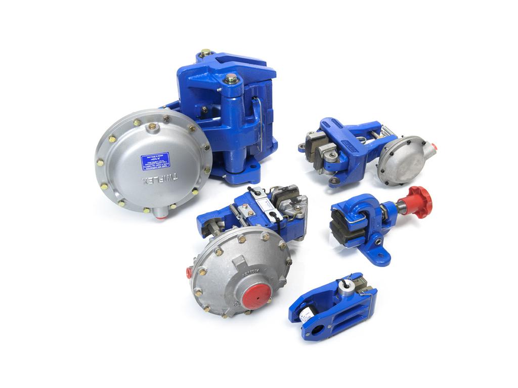

1 Solutions for power transmission MAV-standardisarja

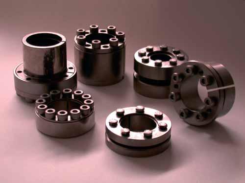
2 L O C K I N G A S S E M B L I E S Shrink disc Mini Series Rigid Couplings
3 our company We are an Italian company world renowned for our creativity and ethics. Established in 1989 we have rapidly built a reputation for professional, reliable and comprehensive service and our extensive product range. We are located in Bosentino in Northern Italy, at the foot of the Dolomites, one of the most beautiful areas of the Alps. our mission Just as our products connect mechanical components in motion technology our purpose is to unite our partners with their goals, feelings, wishes - emotions. We aim to raise the standards in our industry in conjuntion with customers and suppliers who share our goals of quality, safety and environmental conservation. our vision We see the market as a huge mosaic of which manufacturers, suppliers and customers are all part. Together we form a global partnership sharing coon goals for our mutual benefit. In this mosaic we have a central position and wish to be a key point of reference. Sandro Zamboni (MAV President) 2 LOCKING ASSEMBLIES
4 Index Shaft-Hub Connections: Traditional Methods Shaft-Hub Connections: The MAV System MAV Locking Assemblies: main characteristics Applications Information MAV MAV 2005 MAV 3003 MAV 4061 MAV 1008 MAV 5061 MAV MAV 6002 MAV 6903 MAV 1261 Installation instructions Technical Support This catalogue contains complete information for the MAV Locking Assemblies Standard Series. The following pages will help you to find the perfect solution for your application. Should you require assistance with an application, please feel free to contact MAV technical support. Our engineers will be pleased to provide any information you might need MAV S.p.A. All rights reserved. This catalogue may not be reproduced, either wholly or partly without the written authorisation of MAV S.p.A. Information subject to change without prior notification. LOCKING ASSEMBLIES 3
 Keyway and splined locking systems show important disadvantages, in particular under overload and")

, where high radial pressures are generated due to shaft - hub interference.")
5 Shaft-Hub Connections Traditional Methods Fig.1: shaft failure due to fatigue crack (heat treated steel C45) Keyway and splined locking systems show important disadvantages, in particular under overload and frequent torque reversal conditions. Connected parts undergo micro movements which cause them damage. The notch of keyway seat is a stress concentrator which reduces the fatigue strength. The figures show some fatigue failures fractographs of notched shafts (courtesy of ASM International, Metals Handbook, vol 9). Keyways and splines are eliminated by forced fit systems (pressing, heating), where high radial pressures are generated due to shaft - hub interference. A backlash free coupling is obtained. In addition, sections of shafts and bearings can be reduced and, as a consequence, also costs. But this kind of connection shows difficulties during the mounting-dismantling steps. Fig.2: fatigue problem caused by torsion Fig.3: typical fatigue fracture 4 LOCKING ASSEMBLIES
6 Shaft-Hub Connections The MAV System The MAV Locking Devices meet both the advantages of forced fit systems and simplified installation-removal. It is based on the wedge principle: the axial load of the screws generates through the tapers a high radial force that locks the parts by friction. The main features of MAV Locking Devices are: shaft - locking device - hub tolerances are sufficient for easy mounting and correct positioning high manufacturing precision permits close geometrical tolerances, leading to a well balanced coupling, also for high speed conditions high pressures let high torque to be trasmitted, also in addition with bending moment; fretting corrosion is eliminated absence of notches results in enhanced static and dynamical strength, leading to lighter and more cost-effective designs the large variety and the possibility of designing and manufacturing customized units let to find the best solution for any kind of specifications LOCKING ASSEMBLIES 5
7 MAV Locking Assemblies main characteristics MAV series torque capacity bending capacity hub contact pressure self-centering self-locking fixed axial hub position during tightening MAV1061 medium medium medium yes yes yes MAV1062 medium medium medium yes yes no MAV2005 medium low high no no yes MAV3003 low - low no no no MAV4061 high high medium yes yes no MAV1008 high high medium yes yes no MAV5061 medium medium low yes yes yes MAV6901 medium medium medium yes yes no MAV6902 medium medium low yes yes yes MAV6002 high high medium yes yes yes MAV6903 medium medium low yes yes yes MAV1261 medium - low yes yes yes 6 LOCKING ASSEMBLIES
8 MAV Locking Assemblies The following series are produced by MAV, but are not included in this catalogue. Furthermore, MAV is specialized in the design and manufacturing of special and customized solutions, even in small batches. MAV series torque capacity bending capacity hub contact pressure self-centering self-locking fixed axial hub position during tightening MAV2500 medium medium medium yes yes yes MAV4061L high high medium yes yes no MAV3505 low - low no no no MAV3705 low - low yes yes no MAV4005 low - medium no no yes MAV medium - medium yes yes yes MAV4071 medium medium medium yes yes yes MAV1800 medium medium low yes yes yes MAV1071 medium medium medium yes yes yes MAV1072 medium medium medium yes yes no MAV7107 low - low yes yes yes / no For technical features, please visit our website or call or fax LOCKING ASSEMBLIES 7


9 Applications 8 LOCKING ASSEMBLIES
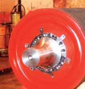
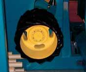
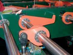
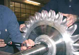
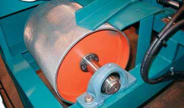
10 Steel mill gear connected with special MAV 7061 Lever arm connected with MAV 1061 Pulley connected with MAV 2005 Conveyor pulley connected with MAV 4061 Clay mill hub connected with two MAV 1008 LOCKING ASSEMBLIES 9
11 Selection MAV frictional locking assemblies provide a keyless, zero backlash connection between shaft and hub, like gears, pulleys, cams, levers, rotors and many others. MAV units are well suited to transmit torque, thrust loads, bending moments and radial loads, separately or simultaneously. Performances listed in this catalogue are calculated without safety factor. The user must consider the specific safety factor, which depends on each application. The following criteria are used for selection of the right unit. The selection should be also based on other specific requirements, like dimensional restrictions, precision of the connection, fixed axial hub position during tightening and others (see characteristics pg. 6 and 7). Torque Where T is the peak torque, select a unit where Mt > T, where Mt = torque capacity. Combined loads When the following loads apply: T = peak torque B = peak bending moment F = peak thrust load Calculate a resultant torque, according to: Mtc T 2 + d 2 F. + (2. B) 2 2 where d = shaft diameter The selected unit has to meet both requirements: Mt > Mtc Mb > B, where Mb = bending capacity Mb depends on each application. Consult our Technical Dept. for specific information. 10 LOCKING ASSEMBLIES
12 Radial load Radial loads are usually associated with pin or axle connections. They apply perpendicular to the centerline of the shaft. The radial load generates a contact pressure Prad, according to: Frad Prad d. Ls where d = shaft diameter Ls = shaft locking assembly contact length Prad is added and subtracted to the contact pressure Ps provided by locking assembly on the shaft. It must be: (Ps + Prad) < Rp 0.2 where Rp 0.2 = yield point of shaft material (Ps - Prad) > 0 Fitting several units arranged in series In applications where two or more units are installed in series, the total torque capacity Mt tot is not linear function of the number of units n. It is calculated as follows: Mt tot = n. Mt. f RS MAV series No. of units (n) where f RS = reduction factor, according to table 1. Table 1 Shaft and hub verification Locking assemblies exert high contact pressures on both shaft (Ps) and hub (Ph). Size and material of shaft and hub must be selected in order to resist the stress generated by the locking assembly and by the applied loads. The following criteria are valid by considering only the contact pressures exerted by the locking assembly. The verification of connected components is based on thick walled cylinder theory. LOCKING ASSEMBLIES 11
13 In case of solid shaft, the material yield point must be greater than shaft contact pressure Ps. In case of hollow shaft, the resistance must be calculated by considering the shaft as a thick walled cylinder, stressed by external pressure Ps. Hub verification is based on the maximum tangential stress, applied to hub bore. The minimum hub outer diameter Dem is calculated as follows: Dem D. Rp P h. C Rp P h. C where D = locking assembly outer diameter (hub bore diameter) Rp 0.2 = yield point of hub material C = stress reduction factor (see fig. 1) For a quick calculation, use table 2 which provides the ratio Dem/D. Dem / D Hub material yield point Rp 0.2 [] Ph C ,0 2,45 2,08 1,87 1,73 1,63 1,56 1,50 1,45 1,41 1,38 1,35 1,33 1,31 1,29 1,27 1,26 1,25 1,24 1, ,8 1,91 1,73 1,61 1,53 1,46 1,41 1,37 1,34 1,31 1,29 1,27 1,25 1,24 1,22 1,21 1,20 1,19 1,18 1,18 0,6 1,58 1,48 1,41 1,36 1,32 1,29 1,26 1,24 1,22 1,21 1,20 1,18 1,17 1,16 1,15 1,15 1,14 1,13 1,13 1,0 2,89 2,32 2,04 1,86 1,73 1,64 1,57 1,51 1,47 1,43 1,40 1,37 1,35 1,33 1,31 1,29 1,28 1,26 1, ,8 2,09 1,86 1,71 1,60 1,53 1,47 1,42 1,38 1,35 1,33 1,30 1,28 1,27 1,25 1,24 1,22 1,21 1,20 1,19 0,6 1,67 1,55 1,47 1,41 1,36 1,33 1,30 1,27 1,25 1,23 1,22 1,20 1,19 1,18 1,17 1,16 1,16 1,15 1,14 1,0 3,61 2,65 2,24 2,00 1,84 1,73 1,65 1,58 1,53 1,48 1,45 1,41 1,39 1,36 1,34 1,32 1,31 1,29 1, ,8 2,32 2,00 1,81 1,69 1,60 1,53 1,47 1,43 1,39 1,36 1,34 1,31 1,29 1,28 1,26 1,25 1,24 1,22 1,21 0,6 1,77 1,62 1,53 1,46 1,40 1,36 1,33 1,30 1,28 1,26 1,24 1,22 1,21 1,20 1,19 1,18 1,17 1,16 1,16 1,0 5,20 3,11 2,49 2,17 1,97 1,83 1,73 1,65 1,59 1,54 1,50 1,46 1,43 1,40 1,38 1,36 1,34 1,32 1, ,8 2,60 2,17 1,93 1,78 1,67 1,59 1,53 1,48 1,44 1,40 1,37 1,35 1,32 1,30 1,29 1,27 1,26 1,25 1,24 0,6 1,88 1,70 1,59 1,51 1,45 1,40 1,36 1,33 1,30 1,28 1,26 1,25 1,23 1,22 1,21 1,20 1,19 1,18 1,17 1,0 3,87 2,83 2,38 2,12 1,95 1,83 1,73 1,66 1,60 1,55 1,51 1,47 1,44 1,41 1,39 1,37 1,35 1, ,8 3,00 2,38 2,07 1,88 1,75 1,66 1,59 1,53 1,48 1,44 1,41 1,38 1,35 1,33 1,31 1,30 1,28 1,27 1,26 0,6 2,00 1,79 1,66 1,56 1,50 1,44 1,40 1,36 1,33 1,31 1,29 1,27 1,25 1,24 1,22 1,21 1,20 1,19 1,18 1,0 5,57 3,32 2,65 2,30 2,08 1,93 1,82 1,73 1,66 1,61 1,56 1,52 1,48 1,45 1,43 1,40 1,38 1, ,8 3,61 2,65 2,24 2,00 1,84 1,73 1,65 1,58 1,53 1,48 1,45 1,41 1,39 1,36 1,34 1,32 1,31 1,29 1,28 0,6 2,14 1,89 1,73 1,62 1,54 1,48 1,43 1,40 1,36 1,34 1,31 1,29 1,27 1,26 1,24 1,23 1,22 1,21 1,20 1,0 4,12 3,00 2,52 2,24 2,05 1,91 1,81 1,73 1,67 1,61 1,57 1,53 1,49 1,46 1,44 1,41 1, ,8 4,73 3,00 2,43 2,13 1,94 1,81 1,71 1,64 1,58 1,53 1,49 1,45 1,42 1,39 1,37 1,35 1,33 1,31 1,30 0,6 2,32 2,00 1,81 1,69 1,60 1,53 1,47 1,43 1,39 1,36 1,34 1,31 1,29 1,28 1,26 1,25 1,24 1,22 1,21 1,0 5,92 3,51 2,79 2,42 2,19 2,02 1,90 1,81 1,73 1,67 1,62 1,57 1,54 1,50 1,47 1,45 1, ,8 8,31 3,51 2,68 2,29 2,06 1,90 1,79 1,70 1,63 1,57 1,53 1,49 1,45 1,42 1,40 1,38 1,36 1,34 1,32 0,6 2,52 2,13 1,90 1,76 1,65 1,57 1,51 1,46 1,42 1,39 1,36 1,34 1,32 1,30 1,28 1,27 1,25 1,24 1,23 1,0 4,36 3,16 2,65 2,35 2,14 2,00 1,89 1,80 1,73 1,67 1,62 1,58 1,54 1,51 1,48 1, ,8 4,36 3,00 2,48 2,19 2,00 1,87 1,77 1,69 1,62 1,57 1,53 1,49 1,46 1,43 1,40 1,38 1,36 1,34 0,6 2,78 2,27 2,00 1,83 1,71 1,62 1,56 1,50 1,46 1,42 1,39 1,36 1,34 1,32 1,30 1,28 1,27 1,26 1,25 1,0 6,24 3,70 2,93 2,54 2,29 2,11 1,98 1,88 1,80 1,73 1,68 1,63 1,59 1,55 1,52 1, ,8 6,24 3,44 2,71 2,34 2,11 1,95 1,84 1,75 1,68 1,62 1,57 1,53 1,49 1,46 1,43 1,41 1,39 1,37 0,6 3,13 2,44 2,11 1,91 1,78 1,68 1,60 1,54 1,49 1,45 1,42 1,39 1,36 1,34 1,32 1,30 1,29 1,27 1,26 1,0 4,58 3,32 2,77 2,45 2,24 2,08 1,96 1,87 1,80 1,73 1,68 1,63 1,59 1,56 1, ,8 4,12 3,00 2,52 2,24 2,05 1,91 1,81 1,73 1,67 1,61 1,57 1,53 1,49 1,46 1,44 1,41 1,39 0,6 3,61 2,65 2,24 2,00 1,84 1,73 1,65 1,58 1,53 1,48 1,45 1,41 1,39 1,36 1,34 1,32 1,31 1,29 1,28 Table 2 12 LOCKING ASSEMBLIES
14 If the hub has a different configuration, consider the most similar shape or the worst condition. Our Technical Dept. is at your disposal for technical assistance. Fig. 1 Stress reduction factor C valid for all series B < 1.5xH 1.5xH < B < 2xH B > 2xH Self-centering and self-locking units Material SELF-CENTERING units provide an excellent centering of the connection. Concentricity and perpendicularity range from 0.02 to Self-centering characteristic depends on length and taper angle, manufacturing process and proper installation. If the locking assembly is not self-centering, a pre-centering hub section is needed in order to obtain an excellent centering of the connection. SELF-LOCKING units ensure the transmission of loads even in case of loosening of the screws. In addition, the screws are not subject to dynamic stress (typical when bending moment applies), which causes fatigue failure. Self-locking characteristic depends on taper angle. Removal of self-locking units is obtained by means of integrated push-off threads. Removal of self-releasing units is obtained by loosening the locking screws. MAV locking assemblies are manufactured from carbon and heat treated alloy steels. In order to improve corrosion resistance, all units are available in different grades of stainless steel (reduction of performances approx. 50%), as well as supplied with different surface coatings like zinc plating, nickel plating and phosphate treatment. Lubrication Locking assemblies are lubricated with ordinary machine oil. Stainless steel units are lubricated with food grade oil, quality H-1 according to FDA. Shaft and hub must be oiled as well. Do not use low friction lubricants (ex. Molybdenum Disulfide based grease) which strongly reduce the performances of the units. Temperature influence Working temperature ranges from 20 C to +150 C. Locking assemblies work correctly as long as temperature changes apply equally to shaft and hub. Different materials must be used if the connection works in temperatures out of the above mentioned range. LOCKING ASSEMBLIES 13
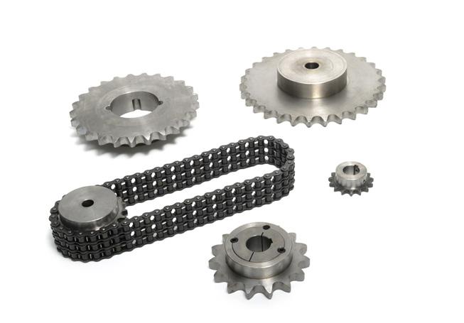
15 MAV 1061 Standard Series DIMENSIONS SCREWS PERFORMANCES WEIGHT kg d x D D1 L2 L1 L Ma Mt Fax Ps Ph size kn 14 x 28 32,0 17,0 20,5 24,5 M ,07 15 x 28 32,0 17,0 20,5 24,5 M ,06 16 x 32 37,0 18,0 21,5 25,5 M ,09 18 x 47 52,0 22,5 28,5 34,5 M ,30 19 x 47 52,0 22,5 28,5 34,5 M ,30 20 x 47 52,0 22,5 28,5 34,5 M ,30 22 x 47 52,0 22,5 28,5 34,5 M ,30 24 x 50 56,5 22,5 28,5 34,5 M ,30 25 x 50 56,5 22,5 28,5 34,5 M ,30 28 x 55 61,5 22,5 28,5 34,5 M ,40 30 x 55 61,5 22,5 28,5 34,5 M ,30 32 x 60 66,5 22,5 28,5 34,5 M ,40 35 x 60 66,5 22,5 28,5 34,5 M ,40 38 x 65 71,5 22,5 28,5 34,5 M ,50 40 x 65 71,5 22,5 28,5 34,5 M ,40 42 x 75 83,5 26,5 34,5 42,5 M ,80 45 x 75 83,5 26,5 34,5 42,5 M ,70 48 x 80 88,5 26,5 34,5 42,5 M ,80 50 x 80 88,5 26,5 34,5 42,5 M ,80 55 x 85 93,5 26,5 34,5 42,5 M ,80 60 x 90 98,0 26,5 34,5 42,5 M ,90 65 x ,0 26,5 34,5 42,5 M ,90 70 x ,0 30,5 40,5 50,5 M ,70 75 x ,0 30,5 40,5 50,5 M ,80 80 x ,0 30,5 40,5 50,5 M ,90 85 x ,0 30,5 40,5 50,5 M ,00 90 x ,0 30,5 40,5 50,5 M ,00 95 x ,0 30,5 40,5 50,5 M , x ,0 33,0 45,0 57,0 M , x ,0 33,0 45,0 57,0 M , x ,0 33,0 45,0 57,0 M , x ,0 41,0 55,0 69,0 M , x ,0 41,0 55,0 69,0 M , x ,0 41,0 55,0 69,0 M , x ,0 41,0 55,0 69,0 M , x ,0 51,0 65,0 79,0 M , x ,0 51,0 65,0 79,0 M , x ,0 51,0 65,0 79,0 M , x ,0 51,0 65,0 79,0 M , x ,0 57,0 73,0 89,0 M , x ,0 57,0 73,0 89,0 M , x ,0 57,0 73,0 89,0 M , x ,0 67,0 85,0 103,0 M , x ,0 67,0 85,0 103,0 M , x ,0 82,0 102,0 122,0 M , x ,0 82,0 102,0 122,0 M , x ,0 94,0 116,0 138,0 M , x ,0 94,0 116,0 138,0 M , x ,0 94,0 116,0 138,0 M ,50 Example of order: MAV x 80 Features Medium capacity Self-centering, self-locking Fixed axial hub position during tightening (MAV 1061 only) Single taper design Tolerances: shaft h8; hub bore H8 Surface finish of shaft and hub bore Ra < 3.2 μm Application examples Simultaneous connection of chain sprocket and conveyor pulley 14 LOCKING ASSEMBLIES
16 Standard Series MAV 1062 Example of order: MAV x 80 Composition Slotted inner ring, with integrated push-off threads Slotted outer ring Set of socket head cap screws, grade 12.9 Components outer ring inner ring screws Code: Ma: screws tightening torque Mt: transmissible torque with Fax=O kn Fax: transmissible axial load with Mt=O Ps: contact pressure on shaft Ph: contact pressure in hub bore d x D DIMENSIONS SCREWS PERFORMANCES L1 L size Ma Mt Fax kn Ps Ph WEIGHT kg 14 x 32 21,5 25,5 M ,09 15 x 32 21,5 25,5 M ,09 16 x 32 21,5 25,5 M ,08 18 x 47 28,5 34,5 M ,30 19 x 47 28,5 34,5 M ,30 20 x 47 28,5 34,5 M ,30 22 x 47 28,5 34,5 M ,20 24 x 50 28,5 34,5 M ,30 25 x 50 28,5 34,5 M ,30 28 x 55 28,5 34,5 M ,30 30 x 55 28,5 34,5 M ,30 32 x 60 28,5 34,5 M ,40 35 x 60 28,5 34,5 M ,30 38 x 65 28,5 34,5 M ,40 40 x 65 28,5 34,5 M ,40 42 x 75 34,5 42,5 M ,70 45 x 75 34,5 42,5 M ,60 48 x 80 34,5 42,5 M ,70 50 x 80 34,5 42,5 M ,70 55 x 85 34,5 42,5 M ,80 60 x 90 34,5 42,5 M ,80 65 x 95 34,5 42,5 M ,90 70 x ,5 50,5 M ,60 75 x ,5 50,5 M ,60 80 x ,5 50,5 M ,70 85 x ,5 50,5 M ,80 90 x ,5 50,5 M ,90 95 x ,5 50,5 M , x ,0 57,0 M , x ,0 57,0 M , x ,0 57,0 M , x ,0 69,0 M , x ,0 69,0 M , x ,0 69,0 M , x ,0 69,0 M , x ,0 79,0 M , x ,0 79,0 M , x ,0 79,0 M , x ,0 79,0 M , x ,0 89,0 M , x ,0 89,0 M , x ,0 89,0 M , x ,0 103,0 M , x ,0 103,0 M , x ,0 122,0 M , x ,0 122,0 M , x ,0 138,0 M , x ,0 138,0 M , x ,0 138,0 M ,30 LOCKING ASSEMBLIES 15


17 MAV 2005 Standard Series DIMENSIONS SCREWS PERFORMANCES d x D L1 L size Ma Mt Fax kn Ps Ph WEIGHT kg 18 x M ,2 19 x M ,2 20 x M ,2 22 x M ,2 24 x M ,2 25 x M ,2 28 x M ,3 30 x M ,3 32 x M ,3 35 x M ,3 38 x M ,3 40 x M ,3 42 x M ,6 45 x M ,5 48 x M ,6 50 x M ,6 55 x M ,6 60 x M ,7 63 x M ,7 65 x M ,7 70 x M ,2 75 x M ,3 80 x M ,4 85 x M ,4 90 x M ,5 95 x M ,6 100 x M ,1 110 x M ,3 120 x M ,5 130 x M ,5 140 x M ,8 150 x M ,0 160 x M ,2 170 x M ,7 180 x M ,0 190 x M ,2 200 x M ,5 220 x M ,8 240 x M ,9 260 x M ,8 280 x M ,3 300 x M ,6 Features Medium capacity Not self-centering, not self-locking (self-releasing) Fixed axial hub position during tightening Two thrust rings with double taper design Low axial dimension Tolerances: shaft h7-h11; hub bore H7-H11 Surface finish of shaft and hub bore Ra < 3.2 μm Application examples gear wheel connection 16 LOCKING ASSEMBLIES
18 Standard Series MAV 2005 L L1 Ød Composition Slotted inner ring Slotted outer ring ØD Example of order: MAV x 80 Double taper front thrust ring, with integrated pull-out threads Double taper rear thrust ring Set of socket head cap screws, grade Zinc plated screws indicate the position of pull- out threads Components thrust ring inner ring outer ring thrust ring screws DIMENSIONS SCREWS PERFORMANCES d x D L1 L size Ma Mt Fax kn Ps Ph WEIGHT kg 320 x M ,4 340 x M ,0 360 x M ,0 380 x M ,0 400 x M ,0 420 x M ,0 440 x M ,0 460 x M ,0 480 x M ,0 500 x M ,0 520 x M ,0 540 x M ,0 560 x M ,0 580 x M ,0 600 x M ,0 620 x M ,0 640 x M ,0 660 x M ,0 680 x M ,0 700 x M ,0 720 x M ,0 740 x M ,0 760 x M ,0 780 x M ,0 800 x M ,0 820 x M ,0 840 x M ,0 860 x M ,0 880 x M ,0 900 x M ,0 920 x M ,0 940 x M ,0 960 x M ,0 980 x M , x M ,0 Code: Ma: screws tightening torque Mt: transmissible torque with Fax=O kn Fax: transmissible axial load with Mt=O Ps: contact pressure on shaft Ph: contact pressure in hub bore LOCKING ASSEMBLIES 17


19 MAV 3003 Standard Series DIMENSIONS PERFORMANCES X WEIGHT kg d x D L Ca Cb Mt Fax Ps Ph kn kn kn 6 x 9 4,5 0,0 4,7 3 1, ,001 7 x 10 4,5 0,0 5,4 4 1, ,001 8 x 11 4,5 0,0 6,2 5 1, ,002 9 x 12 4,5 7,6 7,0 7 1, , x 13 4,5 7,0 7,8 8 1, , x 15 4,5 7,0 9,3 12 2, , x 16 4,5 6,6 10,1 14 2, , x 18 6,3 11,2 15,5 23 3, , x 19 6,3 10,6 16,7 27 3, , x 20 6,3 10,0 17,8 31 3, , x 21 6,3 9,5 18,9 35 4, , x 22 6,3 9,1 20,0 39 4, , x 24 6,3 12,7 21,1 43 4, , x 25 6,3 12,2 22,2 48 4, , x 26 6,3 9,3 24,4 58 5, , x 28 6,3 8,6 26,6 69 5, , x 30 6,3 10,1 27,8 75 6, , x 32 6,3 7,5 31,1 94 6, , x 35 6,3 8,6 33, , , x 36 6,3 7,8 35, , , x 40 7,0 9,9 44, , , x 42 7,0 11,4 45, , , x 44 7,0 10,9 47, , , x 45 8,0 13,6 55, , , x 48 8,0 15,4 58, , , x 52 10,0 23,8 81, , , x 55 10,0 22,6 86, , , x 57 10,0 21,8 90, , , x 62 10,0 21,4 99, , , x 64 12,0 28,7 122, , , x 68 12,0 27,0 130, , , x 71 12,0 25,8 137, , , x 73 12,0 25,1 141, , , x 79 14,0 30,6 178, , , x 80 14,0 30,2 181, , , x 84 14,0 32,2 191, , , x 91 17,0 44,4 251, , , x 96 17,0 44,9 267, , , x ,0 42,6 282, , , x ,0 40,5 298, , ,200 Features Low capacity Not self-centering, not self-locking (self-releasing) Single taper design Low axial and radial dimensions Thrust ring is needed (not supplied by MAV) Slotted execution also available Tolerances (for shaft dia. 38): shaft h6; hub bore H7 Tolerances (for shaft dia. > 38): shaft h8; hub bore H8 Surface finish of shaft and hub bore Ra < 0.8 μm Components outer ring inner ring 18 LOCKING ASSEMBLIES
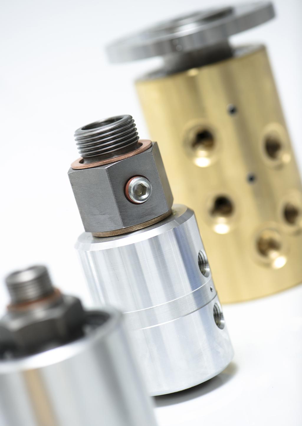
20 Standard Series MAV 3003 L Ød ØD Example of order: MAV x 57 Composition Inner ring Outer ring Application examples Connection of seal and flange of a pneumatic cylinder DIMENSIONS PERFORMANCES X WEIGHT kg d x D L Ca Cb Mt Fax Ps Ph kn kn kn 100 x ,0 60, , ,4 110 x ,0 60, , ,4 120 x ,0 56, , ,5 130 x ,0 94, , ,8 140 x ,0 88, , ,9 150 x ,0 82, , ,0 160 x ,0 78, , ,0 170 x ,0 110, , ,5 180 x ,0 104, , ,6 190 x ,0 105, , ,7 200 x ,0 131, , ,3 210 x ,0 125, , ,5 220 x ,0 120, , ,6 230 x ,0 149, , ,4 240 x ,0 143, , ,6 250 x ,0 169, , ,6 260 x ,0 173, , ,8 270 x ,0 167, , ,0 280 x ,0 202, , ,3 290 x ,0 196, , ,5 300 x ,0 190, , ,7 320 x ,0 271, , ,7 340 x ,0 257, , ,4 360 x ,0 245, , ,0 380 x ,0 234, , ,7 400 x ,0 224, , ,2 420 x ,0 224, , ,8 440 x ,0 215, , ,5 460 x ,0 209, , ,0 480 x ,0 201, , ,5 500 x ,0 194, , ,5 Code: Ma: screws tightening torque Mt: transmissible torque with Fax=O kn Fax: transmissible axial load with Mt=O Ca: assembling load Cb: locking load Ps: contact pressure on shaft Ph: contact pressure in hub bore X: thrust flange - hub distance LOCKING ASSEMBLIES 19

21 MAV 4061 Standard Series L L1 Ød ØD Example of order: MAV x 80 Features High capacity Self-centering, self-locking Two thrust rings with single taper design Tolerances: shaft h8; hub bore H8 Composition Slotted front thrust ring, with integrated push-off holes Slotted rear thrust ring Slotted outer ring, with integrated push-off threads Set of socket head cap screws, grade 12.9 Surface finish of shaft and hub bore Ra < 3.2 μm Application examples Components thrust ring outer ring thrust ring Simultaneous connection of two shafts with hollow shaft and hub with MAV 4061 and shrink disc MAV 2008 screws 20 LOCKING ASSEMBLIES
22 Standard Series MAV 4061 DIMENSIONS SCREWS PERFORMANCES d x D L1 L Ma Mt Fax Ps Ph size kn 24 x M ,4 25 x M ,4 28 x M ,4 30 x M ,4 32 x M ,6 35 x M ,6 38 x M ,0 40 x M ,0 42 x M ,0 45 x M ,9 48 x M ,3 50 x M ,2 55 x M ,3 60 x M ,4 65 x M ,5 70 x M ,8 75 x M ,0 80 x M ,1 85 x M ,3 90 x M ,5 95 x M ,6 100 x M ,6 110 x M ,1 120 x M ,5 130 x M ,0 140 x M ,5 150 x M ,1 160 x M ,6 170 x M ,1 180 x M ,9 190 x M ,6 200 x M ,5 220 x M ,5 240 x M ,5 260 x M ,5 280 x M ,5 300 x M ,5 320 x M ,0 340 x M ,5 360 x M ,0 380 x M ,5 400 x M ,0 420 x M ,0 440 x M ,0 460 x M ,5 480 x M ,0 500 x M ,5 520 x M ,0 540 x M ,0 560 x M ,5 580 x M ,0 600 x M ,0 WEIGHT kg Pinion gear connected with MAV The resisting ring is used to compensate the pressure generated by the locking assembly in the zone adjacent to the pinion gear. Code: Ma: screws tightening torque Mt: transmissible torque with Fax=O kn Fax: transmissible axial load with Mt=O Ps: contact pressure on shaft Ph: contact pressure in hub bore LOCKING ASSEMBLIES 21


23 MAV 1008 Standard Series Example of order: MAV x 145 Features High capacity Self-centering, self-locking Two thrust rings with single taper design Tolerances: shaft h7-h11; hub bore H7-H11 Composition Slotted front thrust ring, with integrated push-off holes Slotted rear thrust ring Slotted outer ring, with integrated push-off threads Set of socket head cap screws, grade 12.9 Surface finish of shaft and hub bore Ra < 3.2 μm Application examples Components thrust ring outer ring thrust ring Brake disc connected with MAV 1008 and flange screws 22 LOCKING ASSEMBLIES
24 Standard Series MAV 1008 DIMENSIONI SCREWS PERFORMANCES d x D L1 L size Ma Mt Fax kn Ps Ph WEIGHT kg 70 x M ,3 75 x M ,4 80 x M ,5 85 x M ,6 90 x M ,7 95 x M ,9 100 x M ,1 110 x M ,3 120 x M ,6 130 x M ,4 140 x M ,7 150 x M ,2 160 x M ,6 170 x M ,5 180 x M ,9 190 x M ,2 200 x M ,6 220 x M ,9 240 x M ,0 260 x M ,5 280 x M ,0 300 x M ,7 320 x M ,5 340 x M ,5 360 x M ,0 380 x M ,5 400 x M ,0 420 x M ,5 440 x M ,0 460 x M ,0 480 x M ,0 500 x M ,0 520 x M ,0 540 x M ,0 560 x M ,0 580 x M ,0 600 x M ,0 Connection of end disc of conveyor pulley for mining industry. The MAV 1008 allows an optimized T shaped design of the end disc, which is lighter and cheaper and compensates higher bending moment generated by the tension of the belt. Code: Ma: screws tightening torque Mt: transmissible torque with Fax=O kn Fax: transmissible axial load with Mt=O Ps: contact pressure on shaft Ph: contact pressure in hub bore LOCKING ASSEMBLIES 23


25 MAV 5061 Standard Series L L1 L2 Ød ØD ØD1 Features Medium capacity Self-centering, self-locking Fixed axial hub position during tightening Single taper design Example of order: MAV x 65 Application examples Well suited for connection of thin walled hubs Tolerances: shaft h7-h11; hub bore H7-H11 Surface finish of shaft and hub bore Ra < 3.2 μm Composition slotted inner ring, with integrated push-off threads Slotted outer ring Spacer Set of socket head cap screws, grade 12.9 Connection of fan with thin walled hub 24 LOCKING ASSEMBLIES
26 Standard Series MAV 5061 d x D DIMENSIONS SCREWS PERFORMANCES D1 L2 L1 L size Ma Mt Fax kn Ps Ph WEIGHT kg 6 x ,0 26,0 M ,04 7 x ,0 29,0 M ,04 8 x ,0 29,0 M ,05 9 x ,0 31,0 M ,06 10 x ,0 31,0 M ,06 11 x ,5 31,5 M ,07 12 x ,5 31,5 M ,07 13 x ,5 31,5 M ,11 14 x ,5 31,5 M ,11 15 x ,5 42,5 M ,20 16 x ,5 42,5 M ,20 17 x ,5 45,5 M ,20 18 x ,5 45,5 M ,30 19 x ,5 45,5 M ,30 20 x ,5 45,5 M ,30 22 x ,0 53,0 M ,40 24 x ,0 53,0 M ,40 25 x ,0 53,0 M ,40 28 x ,0 53,0 M ,40 30 x ,0 53,0 M ,40 32 x ,0 53,0 M ,50 35 x ,0 60,0 M ,50 38 x ,0 60,0 M ,60 40 x ,0 60,0 M ,70 42 x ,0 60,0 M ,70 45 x ,0 78,0 M ,10 48 x ,0 78,0 M ,10 50 x ,0 78,0 M ,30 55 x ,0 89,0 M ,60 60 x ,0 89,0 M ,80 65 x ,0 89,0 M ,10 70 x ,0 106,0 M ,80 75 x ,0 106,0 M ,10 80 x ,0 106,0 M ,20 85 x ,0 106,0 M ,50 90 x ,0 106,0 M ,90 95 x ,0 106,0 M , x ,0 119,0 M , x ,0 119,0 M , x ,0 140,0 M , x ,0 140,0 M ,50 Code: Ma: screws tightening torque Mt: transmissible torque with Fax=O kn Fax: transmissible axial load with Mt=O Ps: contact pressure on shaft Ph: contact pressure in hub bore Special inverted MAV 5061 for connection of aluminum gear. Components outer ring spacer inner ring screws LOCKING ASSEMBLIES 25
27 MAV 6901 Standard Series d x D DIMENSIONS SCREWS PERFORMANCES L1 L size Ma Mt Fax kn Ps Ph WEIGHT kg 18 x 47 42,0 48,0 M ,4 19 x 47 42,0 48,0 M ,4 20 x 47 42,0 48,0 M ,4 22 x 47 42,0 48,0 M ,3 24 x 50 43,0 49,0 M ,4 25 x 50 43,0 49,0 M ,4 28 x 55 43,0 49,0 M ,5 30 x 55 43,0 49,0 M ,5 32 x 60 43,0 49,0 M ,5 35 x 60 43,0 49,0 M ,5 38 x 65 43,0 49,0 M ,6 40 x 65 43,0 49,0 M ,5 42 x 75 50,5 58,5 M ,0 45 x 75 50,5 58,5 M ,9 48 x 80 50,5 58,5 M ,0 50 x 80 50,5 58,5 M ,0 55 x 85 50,5 58,5 M ,0 60 x 90 50,5 58,5 M ,1 63 x 95 50,5 58,5 M ,2 65 x 95 50,5 58,5 M ,2 70 x ,0 70,0 M ,2 75 x ,0 70,0 M ,4 80 x ,0 70,0 M ,5 85 x ,0 70,0 M ,7 90 x ,0 70,0 M ,8 95 x ,0 70,0 M ,9 100 x ,0 83,0 M ,2 110 x ,0 83,0 M ,1 120 x ,0 83,0 M ,9 130 x ,0 83,0 M ,9 140 x ,0 86,0 M ,2 150 x ,0 86,0 M ,5 160 x ,0 86,0 M ,0 170 x ,0 86,0 M ,4 180 x ,0 86,0 M ,8 190 x ,0 86,0 M ,2 200 x ,0 86,0 M ,9 220 x ,0 102,0 M ,2 240 x ,0 102,0 M ,3 260 x ,0 102,0 M ,0 280 x ,0 127,0 M ,0 300 x ,0 127,0 M ,0 320 x ,0 148,0 M ,0 340 x ,0 148,0 M ,0 360 x ,0 174,0 M ,0 380 x ,0 174,0 M ,0 400 x ,0 174,0 M ,0 Features Medium capacity Self-centering, self-locking Fixed axial hub position during tightening (MAV 6902 only) Single taper design High contact length, low contact pressures Tolerances: shaft h8; hub bore H8 Surface finish of shaft and hub bore Ra < 3.2 μm Composition Slotted inner ring, with integrated push-off threads Slotted outer ring Spacer (MAV 6902 only) Set of socket head cap screws, grade 12.9 Code: Ma: screws tightening torque Mt: transmissible torque with Fax=O kn Fax: transmissible axial load with Mt=O Ps: contact pressure on shaft Ph: contact pressure in hub bore 26 LOCKING ASSEMBLIES


28 Standard Series MAV 6902 Example of order: MAV x 80 Components outer ring spacer inner ring screws Example of order: MAV x 80 DIMENSIONS SCREWS PERFORMANCES WEIGHT kg d x D D1 L2 L1 L Ma Mt Fax Ps Ph size kn 18 x ,0 42,0 48,0 M ,4 19 x ,0 42,0 48,0 M ,4 20 x ,0 42,0 48,0 M ,4 22 x ,0 42,0 48,0 M ,4 24 x ,0 43,0 49,0 M ,4 25 x ,0 43,0 49,0 M ,4 28 x ,0 43,0 49,0 M ,5 30 x ,0 43,0 49,0 M ,5 32 x ,0 43,0 49,0 M ,5 35 x ,0 43,0 49,0 M ,5 38 x ,0 43,0 49,0 M ,6 40 x ,0 43,0 49,0 M ,6 42 x ,5 50,5 58,5 M ,0 45 x ,5 50,5 58,5 M ,9 48 x ,5 50,5 58,5 M ,0 50 x ,5 50,5 58,5 M ,0 55 x ,5 50,5 58,5 M ,1 60 x ,5 50,5 58,5 M ,1 63 x ,5 50,5 58,5 M ,3 65 x ,5 50,5 58,5 M ,2 70 x ,0 60,0 70,0 M ,3 75 x ,0 60,0 70,0 M ,5 80 x ,0 60,0 70,0 M ,6 85 x ,0 60,0 70,0 M ,7 90 x ,0 60,0 70,0 M ,9 95 x ,0 60,0 70,0 M ,0 100 x ,0 71,0 83,0 M ,4 110 x ,0 71,0 83,0 M ,7 120 x ,0 71,0 83,0 M ,0 130 x ,0 71,0 83,0 M ,0 140 x ,0 82,0 86,0 M ,3 150 x ,0 82,0 86,0 M ,7 160 x ,0 82,0 86,0 M ,2 170 x ,0 82,0 86,0 M ,6 180 x ,0 82,0 86,0 M ,1 190 x ,0 82,0 86,0 M ,5 200 x ,0 82,0 86,0 M ,1 220 x ,0 98,0 102,0 M ,5 240 x ,0 98,0 102,0 M ,6 260 x ,0 98,0 102,0 M ,3 280 x ,0 121,0 127,0 M ,5 300 x ,0 121,0 127,0 M ,5 320 x ,0 140,0 148,0 M ,0 340 x ,0 140,0 148,0 M ,0 360 x ,0 164,0 174,0 M ,0 380 x ,0 164,0 174,0 M ,0 400 x ,0 164,0 174,0 M ,0 LOCKING ASSEMBLIES 27


29 MAV 6002 Standard Series d x D DIMENSIONS D1 L3 L2 L1 L size 1 SCREWS Ma size 2 Ma 30 x M 8 41 M x M 8 41 M x M 8 41 M x M 8 41 M x M 8 41 M x M M x M M x M M x M M x M M x M M x M M x M M x M M x M M x M M x M M x M M x M M x M M x M M x M M x M M x M M x M M x M M x M M x M M x M M x M M x M M x M M x M M x M M x M M x M M x M M x M M x M M x M M x M M x M M x M M x M M x M M x M M x M M Features High capacity Self-centering, self-locking Fixed axial hub position during tightening Single taper design with two outer rings Well suited to transmit high bending moments Tolerances: shaft h7-h11; hub bore H7-H11 Surface finish of shaft and hub bore Ra < 3.2 μm Application examples M t2 P h2 M tot M t1 P h1 Simultaneous connection of two gear wheels 28 LOCKING ASSEMBLIES
30 Standard Series MAV 6002 L3 Composition Slotted inner ring, with integrated push-off threads Two slotted outer rings Two sets of different sizes socket head cap screws, grade 12.9 Components outer rings inner ring screws L L1 L2 L3 Ød ØD Example of order: MAV x 85 ØD1 Code: Ma: screws tightening torque Mt: transmissible torque with Fax=O kn Fax: transmissible axial load with Mt=O Ps: contact pressure on shaft Ph: contact pressure in hub bore DIMENSIONS d x D M t1 M t2 M tot PERFORMANCES Fax 1 kn Fax 2 kn Fax tot kn Ps 1 Ph 1 Ps 2 Ph 2 WEIGHT kg 30 x ,8 32 x ,9 35 x ,9 38 x ,0 40 x ,0 42 x ,6 45 x ,5 48 x ,7 50 x ,6 55 x ,7 60 x ,9 65 x ,0 70 x ,6 75 x ,3 80 x ,0 85 x ,7 90 x ,3 95 x ,1 100 x ,6 110 x ,1 120 x ,5 130 x ,5 140 x ,3 150 x ,8 160 x ,5 170 x ,1 180 x ,5 190 x ,3 200 x ,6 220 x ,5 240 x ,6 260 x ,6 280 x ,5 300 x ,3 340 x ,9 380 x ,6 400 x ,4 420 x ,2 440 x ,3 460 x ,8 480 x ,3 500 x ,8 520 x ,3 540 x ,0 560 x ,0 580 x ,0 600 x ,0 LOCKING ASSEMBLIES 29


31 MAV 6903 Standard Series Features Medium capacity Self-centering, self-locking Fixed axial hub position during tightening Single taper design Well suited for axial locking of other components (ex. bearings) adjacent to the hub Tolerances: shaft h8; hub bore H8 Surface finish of shaft and hub bore Ra < 3.2 μm Composition Slotted inner ring Slotted outer ring, with integrated push-off threads Set of socket head cap screws, grade 12.9 Example of order: MAV x 80 Application examples Components inner ring outer ring Fly wheel connection screws 30 LOCKING ASSEMBLIES
32 Standard Series MAV 6903 DIMENSIONS SCREWS PERFORMANCES d x D L1 L size Ma Mt Fax kn Ps Ph WEIGHT kg 20 x M ,3 22 x M ,3 24 x M ,3 25 x M ,3 28 x M ,4 30 x M ,3 32 x M ,4 35 x M ,4 38 x M ,4 40 x M ,4 42 x M ,7 45 x M ,7 48 x M ,8 50 x M ,8 55 x M ,5 60 x M ,9 63 x M ,9 65 x M ,9 70 x M ,8 75 x M ,9 80 x M ,0 85 x M ,1 90 x M ,2 95 x M ,3 100 x M ,4 110 x M ,7 120 x M ,0 130 x M ,9 The specific purpose of series MAV 6903 is the axial locking of other elements adjacent to hub (e.g. bearings) during tightening of locking assembly. The movement of outer ring of locking assembly generates an axial force which is transmitted to hub and, by means of flanges Connection of and spacers, to adjacent elements. press gear for plastic materials Code: Ma: screws tightening torque Mt: transmissible torque with Fax=O kn Fax: transmissible axial load with Mt=O Ps: contact pressure on shaft Ph: contact pressure in hub bore LOCKING ASSEMBLIES 31


33 MAV 1261 Standard Series L L1 L2 Ø d Ø D Ø D1 Example of order: MAV x 67 Features Medium capacity Self-centering, self-locking Fixed axial hub position during tightening Single taper design Zinc plated rings Composition Slotted inner ring, with integrated push-off threads Slotted outer ring Set of socket head cap screws, grade 12.9 LUBRICATION. Rings, shaft, hub bore: OIL-FREE and DRY. Screws: OILED Tolerances: shaft ±0.08 ; hub bore ±0.08 Surface finish of shaft and hub bore Ra < 3.2 μm Application examples Components outer ring inner ring Gear connection screws 32 LOCKING ASSEMBLIES
34 Standard Series MAV 1261 d d inch x D DIMENSIONS SCREWS PERFORMANCES D inch D1 L L1 WEIGHT kg 15,00 x 38, ,0 25,0 19,0 M , ,2 15,88 5/ 8 x 38,10 1 1/ ,0 25,0 19,0 M , ,2 16,00 x 38, ,0 25,0 19,0 M , ,2 17,00 x 38, ,0 25,0 19,0 M , ,2 17,46 11/16 x 38,10 1 1/ ,0 25,0 19,0 M , ,2 18,00 x 38, ,0 25,0 19,0 M , ,2 19,00 x 38, ,0 25,0 19,0 M , ,2 19,05 3/ 4 x 38,10 1 1/ ,0 25,0 19,0 M , ,2 20,00 x 45, ,2 28,2 22,2 M , ,3 20,64 13/16 x 44,45 1 3/ ,2 28,2 22,2 M , ,3 22,00 x 45, ,2 28,2 22,2 M , ,2 22,23 7/ 8 x 44,45 1 3/ ,2 28,2 22,2 M , ,2 23,81 15/16 x 44,45 1 3/ ,2 28,2 22,2 M , ,2 24,00 x 45, ,2 28,2 22,2 M , ,2 25,00 x 45, ,2 28,2 22,2 M , ,2 25,40 1 x 44,45 1 3/ ,2 28,2 22,2 M , ,2 26,99 1 1/16 x 50, ,4 31,4 25,4 M , ,3 28,00 x 51, ,4 31,4 25,4 M , ,3 28,58 1 1/ 8 x 50, ,4 31,4 25,4 M , ,3 30,00 x 51, ,4 31,4 25,4 M , ,3 30,16 1 3/16 x 50, ,4 31,4 25,4 M , ,3 31,75 1 1/ 4 x 50, ,4 31,4 25,4 M , ,3 32,00 x 51, ,4 31,4 25,4 M , ,3 33,34 1 5/16 x 60,33 2 3/ ,0 44,0 38,0 M , ,6 34,00 x 60, ,0 44,0 38,0 M , ,6 34,93 1 3/ 8 x 60,33 2 3/ ,0 44,0 38,0 M , ,6 35,00 x 60, ,0 44,0 38,0 M , ,6 36,00 x 60, ,0 44,0 38,0 M , ,6 36,51 1 7/16 x 60,33 2 3/ ,0 44,0 38,0 M , ,6 38,00 x 60, ,0 44,0 38,0 M , ,5 38,10 1 1/ 2 x 60,33 2 3/ ,0 44,0 38,0 M , ,5 39,69 1 9/16 x 66,68 2 5/ ,8 48,8 42,8 M , ,8 40,00 x 67, ,8 48,8 42,8 M , ,8 41,28 1 5/ 8 x 66,68 2 5/ ,8 48,8 42,8 M , ,8 42,00 x 67, ,8 48,8 42,8 M , ,7 42, /16 x 66,68 2 5/ ,8 48,8 42,8 M , ,7 44,45 1 3/ 4 x 66,68 2 5/ ,8 48,8 42,8 M , ,7 45,00 x 73, ,8 56,8 50,8 M , ,0 46, /16 x 73,03 2 7/ ,8 56,8 50,8 M , ,0 47,63 1 7/ 8 x 73,03 2 7/ ,8 56,8 50,8 M , ,0 48,00 x 73, ,8 56,8 50,8 M , ,0 49, /16 x 73,03 2 7/ ,8 56,8 50,8 M , ,9 50,00 x 73, ,8 56,8 50,8 M , ,9 50,80 2 x 73,03 2 7/ ,8 56,8 50,8 M , ,9 L2 size Ma Mt Fax kn Ps Ph This series is used as an alternative to the hex nut keyless bushings. The force generated by large nut is provided by small quantity of screws, which eliminates the need of large and expensive wrenches and allows easier installation. Pinion gear connection Code: Ma: screws tightening torque Mt: transmissible torque with Fax=O kn Fax: transmissible axial load with Mt=O Ps: contact pressure on shaft Ph: contact pressure in hub bore Pinion gear connection LOCKING ASSEMBLIES 33
35 Installation and removal instructions Installation MAV locking assemblies are supplied ready for installation. Performances are based on a friction coefficient μ=0.12, for lightly oiled rings, screws, shaft and hub bore. It is important NOT TO USE molybdenum disulphide lubricants (ex. Molykote, Never-Seeze or similar). 1. Disengage the rings by loosening the screws or by tightening some of them into the push-off threads (fig.1). 2. Insert the locking assembly and relocate any screw used to separate the rings. 3. Ensure the right position of shaft and hub, then hand tighten the screws. 4. Use torque wrench and set it approx. 5% higher than specified tightening torque. Tighten the screws in a crosswise pattern in several steps. 5. Reset torque wrench to the specified tightening torque and make sure no screw can turn, otherwise repeat the procedure from step 4 for 1 or 2 times. Removal Prior to initiating the removal procedure, check to ensure that no load is acting on the locking assembly, shaft or any mounted component. 1. Remove all screws. Transfer required number of screws into all push-off threads. 2. Tighten the screws in a crosswise pattern in several steps until rings disengage (fig.2). Fig. 1 Fig. 2 NOTE: download from our website or request to our Technical Department, the detailed installation and removal instructions for each MAV series. 34 LOCKING ASSEMBLIES
36 Technical Support Data of application If you need technical assistance to select the right MAV Locking Device for your application, please fill out this questionnaire and send it to us by fax using the following number: Peak torque to be transmitted... T [] Peak axial force to be transmitted... F [kn] Peak bending moment to be transmitted... B [] Peak radial force to be transmitted... Frad [kn] Maximum speed... n [1/min] Operating temperature... To [ C] Ambient temperature... Ta [ C] SHAFT DATA: Size... d [] If hollow-shaft; inner diameter... di [] Material... Yield point... Rp 0,2 [] HUB DATA: Outer diameter... dh [] Length... L [] Material... Yield point... Rp 0,2 [] Describe your application (if possible, please attach a sketch or a drawing) LOCKING ASSEMBLIES 35

37 MAV S.p.A. Via Venezia, Bosentino (TN) Italy Tel Fax C09-ENG 2009 MAV S.p.A. Your local MAV distributor:


38 Voimansiirtokomponentit ja laitekokonaisuudet ovat meille tuttuja, sillä olee yksi johtavista voimansiirtokomponenttien toimittajista Suomessa. Asiantuntijae auttavat mielellään löytämään oikeat ratkaisut tarpeisiinne ja pystye laajan tuotevalikoimae ja kattavan varasto-ohjelman avulla nopeisiin toimituksiin. Edustae kansainvälisesti tunnettuja valmistajia ja tuotemerkkejä tuotteiden ja toiminnan korkea laatu on yksi toimintae kulmakivistä. Palvelee teitä kaikissa voimansiirtoasioissanne yli neljänkyenen vuoden kokemuksella. Solutions for power transmission
Locking Assemblies Shrink Discs Rigid Couplings.
 M I N I Locking Assemblies Shrink Discs Rigid Couplings www.mav.it our company We are an Italian company world renowned for our creativity and ethics. Established in 1989 we have rapidly built a reputation
TRADITIONAL SHAFT HUB CONNECTIONS
 TABLE OF CONTENTS MAV locking devices.... Pg. 2 Traditional shaft hub connections...pg. 3 Advantages of MAV locking devices...pg. 4 The wedge principle..... Pg. 5 Installation removal...pg. 6 Characteristics....
Comparison Chart. extremely difficult. Finally, separated components can rarely be re-used.
 JAN 2014 Traditional Connections Why Go Keyless Keyed Bushing Systems Both QD and Taper-Lock bushing and weld-on hub systems are popular component mounting technologies. Yet both are ultimately keyed connections
RFC SPECIALTY LOCKING DEVICES
 RINGFEDER Products are available from MARYLAND METRICS P.O. Box 261 Owings Mills, MD 21117 USA email: sales@mdmetric.com web: http://mdmetric.com phones: (410)358-3130 (800)638-1830 faxes: (410)358-3142
CLAMPING ELEMENTS SELF-CENTRING RCK 15 TYPE SELF-CENTRING RCK 13 TYPE
 CLAMPING ELEMENTS The clamping system connects one or two component parts solidly to the drive shaft, which allow motion to be transmitted or to withstand an axial thrust. Friction connection enables gaps
Shaft Couplings Flange-Couplings Rigid Shaft Couplings Flexible Couplings
 Shaft Couplings Flange-Couplings Rigid Shaft Couplings Flexible Couplings 44 Edition 2013/2014 RINGSPANN Registered Trademark of RINGSPANN GmbH, Bad Homburg 2 Table of Contents Flange-Couplings Page Flange-Couplings
For advanced drive technology CLAMPEX. Shaft-Hub-Connection. KTR Precision Joints CLAMPEX
 technology CLAMPEX Shaft-Hub-Connection CLAMPEX KTR Precision Joints 07 technology Table of contents Page Brief information 09 Selection and calculation -5 CLAMPEX -Selection Shaft diameter = d 0 10 0
Shaft-Hub-Connections
 Stand: 14.01.2010 Shaft-Hub-Connections Shrink Discs Cone Clamping Elements Star Discs 36 Edition 2012/2013 RINGSPANN Eingetragenes Warenzeichen der RINGSPANN GmbH, Bad Homburg Table of Contents Introduction
Shaft Clamping Elements 8
 Clamping Elements 8 BACK NEXT The Company Cross & orse was established in 14 through the amalgamation of two long standing and well respected companies in the Power Transmission Industry, T.D. Cross and
NEW. Cone Clamping Elements Trantorque Keyless Locking Devices for very small diameters from 3 mm. E03.050e
 Cone Clamping Elements Trantorque Keyless Locking Devices for very small diameters from 3 mm NEW E03.050e Backlash free positioning Excellent concentricity Quick mounting by central clamping nut Issue
RINGFEDER KEYLESS SHAFT/HUB CONNECTIONS LOCKING ASSEMBLIES TM LOCKING ELEMENTS TM SHRINK DISCS W-300-2
 RINGFEDER KEYLESS SHAFT/HUB CONNECTIONS LOCKING ASSEMBLIES TM LOCKING ELEMENTS TM SHRINK DISCS W-300-2 1 Ringfeder Corporation Catalog W-300-1 Shaft-Hub Locking Devices Ringfeder unique frictional, keyless
SIT-LOCK self locking elements
 self locking elements Advantages of on the shaft-hub connection compared with traditional systems Easy assembly and disassembly Both actions take place by locking and unlocking the clamping screws with
Rexnord Tollok Locking Assemblies
 Tollok Catalog Download the most up-to-date version at www.rexnord.com/documentation Rexnord Tollok Locking Assemblies Why Choose Rexnord Tollok Locking Assemblies? Why Choose Rexnord? When it comes to
SKF FX Keyless Bushings
 SKF FX Keyless ushings Contents The SKF brand now stands for more than ever before, and means more to you as a valued customer. While SKF maintains its leadership as a high-quality bearing manufacturer
For advanced drive technology CLAMPEX. Shaft-hub-connection. KTR Precision joints CLAMPEX
 technology CLAMPEX Shaft-hub-connection CLAMPEX KTR Precision joints 227 technology Table of contents Page Brief information 228 Selection and calculation 25-255 CLAMPEX -Selection Shaft diameter = d 0
Locking Assemblies & Locking Elements
 US 01 2016 Locking Assemblies & Locking Elements Partner for Performance www.ringfeder.com Welcome to your system supplier for every aspect of power transmission Today s RINGFEDER POWER TRANSMISSION GMBH
RINGFEDER Locking Assemblies. Catalogue. RfN For high torques & axial loads
 RINGFEDER Locking Assemblies GB 03 04 Catalogue RfN 7014 For high torques & axial loads RINGFEDER Locking Assemblies RfN 7014 Please note that our guarantee refers to our products only. Because of the
TSUBAKI POWER TRANSMISSION COMPONENTS
 TSUBAKI POWER TRANSMISSION COMPONENTS Contents Page Introduction to Shock Relays F-2 "SS" Series Analogue Shock Relays F-3 - F-5 "SD" Series Digital Shock Relays F-6 - F-10 Introduction to F-11 AS Construction/Selection/Installation/Removal
RCK CLAMPING ELEMENTS
 RCK CAMPING EEMENTS SERIES RCK 11 page 6 SERIES RCK 13 7 SERIES RCK 15 8 SERIES RCK 16 9 SERIES RCK 19 10 SERIES RCK 40 11 SERIES RCK 45 12 SERIES RCK 50 13 SERIES RCK 55 14 SERIES RCK 60 15 SERIES RCK
Shrink Discs, Smart-Lock & Shaft Couplings
 RINGFEDER Products are available from MARYLAND METRICS Shrink Discs, Smart-Lock & Shaft Couplings US 08 2009 Partner for performance RINGFEDER Products are available from MARYLAND METRICS P.O. Box 261
GENERAL INFORMATION Locking is the rigid coupling of two or more elements which, in the absence of a coupling device, would otherwise be free to rotat
 123456789012345678901234567890121234567890123456 7 7 7 7 7 7 4567890123456789012123456789012345678901234567890121234567 7 1004 1004 34 7 134567890123456789012123456789012345678901234567890121234567 1234567890123456789012123456789012345678901234567890121234567
Installation and Operating Instructions for ROBA -ES couplings Type 940. _. _ Sizes 14-48
 Table of contents: Please read and observe this Operating Instruction carefully. A possible malfunction or failure of the clutch and damage may be caused by not observing it. Page 1: - Table of contents
Assortment 2013_FPT BOOK.indb /02/13 6:57 PM
 Assortment Contents Why compete against your supplier when you can be our partner Chain Tensioners...14 see Chains section for details Anti-Vibration Mounts...224 Key Steel...225 Motor Rails...226 Self
MAE 322 Machine Design Shafts -3. Dr. Hodge Jenkins Mercer University
 MAE 322 Machine Design Shafts -3 Dr. Hodge Jenkins Mercer University Setscrews Setscrews resist axial and rotational motion They apply a compressive force to create friction The tip of the set screw may
Tsubaki POWER-LOCK Keyless Shaft Locking Solutions
 Tsubaki POWER-LOCK Keyless Shaft Locking Solutions Performance Under Pressure Tsubaki's extensive POWER-LOCK portfolio offers a simple and cost effective solution to problems associated with keyed or machined
Locking elements. Technical information
 Technical information ocking elements.principle of operation. These parts operate on the basis of an interference fit between two conical rings crewed together. The outer ring expands and exerts a pressure
RE / STAR Tolerance Rings STAR Ball Knobs, Knob and Lever Type Handles
 RE 2 970/.99 STAR Tolerance Rings STAR Ball Knobs, Knob and Lever Type Handles STAR Tolerance Rings Product Overview Tolerance rings are made of hard, embossed spring steel strip and belong to the class
Locking Assemblies & Locking Elements
 US 12 2010 Locking Assemblies & Locking Elements Partner for performance www.ringfeder.com A Global Presence For You The RINGFEDER POWER TRANSMISSION GMBH was founded in 1922 in Krefeld, Germany to fabricate
Shaft Couplings Tru-Line Flange-Couplings Rigid Shaft Couplings Flexible Couplings
 Shaft Couplings Tru-Line Flange-Couplings Rigid Shaft Couplings Flexible Couplings Edition 2015/2016 RINGSPANN Registered Trademark of RINGSPANN GmbH, Bad Homburg Table of Contents Tru-Line Flange-Couplings
CONTENT. 1. Syllabus 2. Introduction 3. Shaft 4. Coupling. Rigid coupling. Flange coupling. Sleeve (or) muff coupling Split muff coupling
 muff coupling Split muff coupling") UNIT II 1. Syllabus 2. Introduction 3. Shaft 4. Coupling Rigid coupling CONTENT Flange coupling Protected flange coupling Unprotected flange coupling Marine type flange coupling Sleeve (or) muff coupling
UNIT II 1. Syllabus 2. Introduction 3. Shaft 4. Coupling Rigid coupling CONTENT Flange coupling Protected flange coupling Unprotected flange coupling Marine type flange coupling Sleeve (or) muff coupling
U.S. Tsubaki AS Series
 U.S. TSUBAKI POWER-LOCK U.S. Tsubaki AS Series ENTER THE YLESS SOCIETY Our POWER-LOCK solves your problems. Eliminate backlash damage to keyways from heavy loads the U.S. Tsubaki POWER-LOCK fits tightly
Flexible Couplings 44
 Flexible Couplings 44 RINGSPANN Registered Trademark of RINGSPANN GmbH, Bad Homburg MTY (81) 83 54 10 18 Why RINGSPANN Flexible Couplings? No connection of shafts without clutches It is a well-known fact
Power-Lock shaft-hub locking devices provide simple and highly secure connections.
 POWER-LOCK Power-Lock shaft-hub locking devices provide simple and highly secure connections. AS Series Multipurpose locking devices available in stainless steel and electroless nickelplated finish, in
Frictional Connections Catalogue
 MMADE IN GERMANY Frictional Connections Catalogue ADE IN GERMANY Certified in accordance with DIN ISO 9001:2008 FRICTIONAL CONNECTIONS TECHNOLOGY THAT CONNECTS Dear business partner, STÜWE GmbH & Co. KG
SCHMIDT-KUPPLUNG GmbH
 Loewe GK About us Many years of experience For 50 years, we have been advising machine manufacturers as partners for compact coupling systems. Our experience in power transmission has given us extensive
Selection Tool. on the Internet at in the section MÄDLER -Tools. Other sizes and designs on request. Connecting Shafts Page 766
 Couplings Overview Friction Clutches Friction Clutches Type B Axial Arrangement Friction Clutches Type C Transversal Flexibility Sliding Hubs with Torsionally-Flexible Coupling Multi-Disk Friction Clutches
LIGHTWEIGHT AND COMPACT. SERIES SL Nm. single-position multi-position. THE ultimate COUPLING from Nm
 LIGHTWEIGHT AND COMPACT L SAFETY COUPLINGS TOQLIGHT SEIES SL 5 700 Nm THE ultimate COUPLING from 5 700 Nm SEIES SL DESIGN / FEATUES Extremely lightweight construction Up to 60 % weight reduction in comparison
Chapter 7. Shafts and Shaft Components
 Chapter 7 Shafts and Shaft Components 2 Chapter Outline Introduction Shaft Materials Shaft Layout Shaft Design for Stress Deflection Considerations Critical Speeds for Shafts Miscellaneous Shaft Components
Intelligent Drivesystems NORD GRIPMAXX. Keyless Bushing System DRIVESYSTEMS F5210
 Intelligent Drivesystems NORD GRIPMAXX Keyless Bushing System F5210 The NORD GRIPMAXX Keyless Bushing System Concept Overview The NORD Gripmaxx Bushing System offers keyless interchangeable bushings for
CLASSIFICATION OF ROLLING-ELEMENT BEARINGS
 CLASSIFICATION OF ROLLING-ELEMENT BEARINGS Ball bearings can operate at higher speed in comparison to roller bearings because they have lower friction. In particular, the balls have less viscous resistance
Rigid Couplings. P-1686-TBW 2/17... TB Wood s F7-1
 Rigid Couplings F7 F7-1 AVS Series Couplings AVS Series (Adjustable Vertical Spacer) Coupling used for vertical turbine pumps No flexible element Integral nut used for infinite adjustment of pump turbine
MINIATURE METAL BELLOWS COUPLINGS
 VERSATILE AND PRECISE. Courtesy of CMA/Flodyne/Hydradyne Motion Control Hydraulic Pneumatic Electrical Mechanical (800) 426-5480 www.cmafh.com MINIATURE METAL BELLOWS COUPLINS SERIES MK 0.05 10 Nm THE
RIGIFLEX -N RADEX -N. Steel laminae coupling. Steel laminae coupling. You will find continuously updated data in our online catalogue at
 117 Table of contents 117 Coupling selection steel laminae coupling 119 Description of coupling 121 General information 122 Types and applications 123 Technical data 124 Standard types 126 Special types
TORQLIGHT SAFETY COUPLINGS
 LIGHTWEIGHT AND COMPACT single-position TOQLIGHT SAFETY COUPLINGS SEIES SL 10 700 Nm THE ULTIMATE COUPLING FOM 10 700 Nm SEIES SL DESIGN / FEATUES Extremely lightweight construction Up to 60 % weight reduction
Sensor-Bearing Units Steer-By-Wire Modules Mast Height Control units Other sensorized units
 Mechatronics Sensor-Bearing Units... 957 Steer-By-Wire Modules... 967 Mast Height Control units... 969 Other sensorized units... 971 955 Sensor-Bearing Units SKF Sensor-Bearing Units... 958 SKF Explorer
Please read these Operational Instructions carefully and follow them accordingly!
 Sizes 3 to 5 Please read these Operational Instructions carefully and follow them accordingly! Ignoring these Instructions may lead to malfunctions or to coupling failure, resulting in damage to other
Angular contact ball bearings
 Angular contact ball bearings Single row angular contact ball bearings... 409 Double row angular contact ball bearings... 433 Four-point contact ball bearings... 451 Double row cam rollers... 463 405 Angular
4 Self aligning ball bearings
 Rolling bearings 4 Self aligning ball bearings Designs and variants... 538 Basic design bearings... 539 Bearings with an extended inner ring.. 540 Cages... 540 Sealing solutions... 540 Greases for sealed
Shaft Couplings. Edition 2015/2016. Tru-Line Flange-Couplings Rigid Shaft Couplings Flexible Couplings
 Shaft Couplings Tru-Line Flange-Couplings Rigid Shaft Couplings Flexible Couplings Edition 2015/2016 RINGSPANN Registered Trademark of RINGSPANN GmbH, Bad Homburg 2 Table of Contents Tru-Line Flange-Couplings
Products Catalogue. Quality Guaranteed
 Products Catalogue CHAINS The GB range of Chains, Sprockets, Couplings and Pulleys has evolved from 20 years expertise in the importation and sale of the products locally in the Australia. The GB range
Bevel gearboxes. Catalogue
 Bevel gearboxes Catalogue INDEX Bevel gearbox description... page 2 Manufacturing features... page 2 Materials and components... page 4 Bevel gearbox selection... page 5 Thermal power limit... page 7
Specifications. Trantorque GT CALL FAX
 GT Specifications The following pages contain engineering data and product specifications for GT. For CAD drawings of GT, please click on the part number to download the drawing. All drawings are in AutoCAD
OVERLOAD CLUTCHES FOR INDEX DRIVES
 The Driving Force in Automation OVERLOAD CLUTCHES FOR INDEX DRIVES WARNING WARNING This is a controlled document. It is your responsibility to deliver this information to the end user of the CAMCO indexer.
Bearings and Spacers
 Bearings and Spacers Section Contents Ball Bearings P4...Page 12 2 Bronze Bearings...Page 12 3 Moulded Bearings...Page 12 4 Bearing Pre load Washers...Page 12 Bearing Spacers...Page 12 6 Technical Information...Page
Standard with cone bushing. Backlash-free Safety Clutch
 EAS -Compact ratchetting clutch/synchronous clutch The Backlash-free Safety Clutch for Standard with cone bushing Packaging Machinery Machine Tools Paper Machinery Indexing Drives Servo Motors EAS -NC
In-house development Own manufacturing Sole distributor in Germany Working with distributors worldwide
 In-house development Own manufacturing Sole distributor in Germany Working with distributors worldwide External Clamping devices Overview 3073 Mini-Range For very low torque transmission Very small profile
GatesFacts Technical Information Library Gates Compass Power Transmission CD-ROM version 1.2 The Gates Rubber Company Denver, Colorado USA
 MAKING THE RIGHT SHAFT CONNECTIONS Daniel Schwartz & Gary Porter Power Transmission Design August, 1996 Securing a belt pulley to a drive shaft often seems like such a routine task, that engineers and
3. BEARING ARRANGEMENT DESIGN
 3. BEARING ARRANGEMENT DESIGN 3.1 GENERAL PRINCIPLES OF ROLLING BEARING ARRANGEMENT DESIGN Rotating shaft or another component arranged in rolling bearings is guided by them in radial as well as in axial
Power Transmission Solutions
 RINGFEDER Products are available from MARYLAND METRICS Power Transmission Solutions 11 2011 Partners for performance RINGFEDER Products are available from MARYLAND METRICS P.O. Box 261 Owings Mills, MD
TOOLFLEX Operating-/Assembly Instructions
 D-807 Rheine heet: 5810 EN 1 of 19 Backlash-free, torsionally stiff and maintenance-free coupling is a backlash-free, torsionally stiff and maintenance-free metal bellow-type coupling designed to be used
Chapter 11. Keys, Couplings and Seals. Keys. Parallel Keys
 Chapter 11 Keys, Couplings and Seals Material taken for Keys A key is a machinery component that provides a torque transmitting link between two power-transmitting elements. The most common types of keys
ROSTA Tensioning Motorbases Type MB. self-adjusting maintenance-free overload-proof non-slip dampen harmful vibrations extend belt drive
 Technology ROSTA Tensioning Type MB for Belt Drives The ROSTA elastic tensioning motorbase type MB, with the rubber suspension unit as swivel mounting, compensates continuously for all stretching, hopping,
DESIGN OF MACHINE MEMBERS - I
 R10 Set No: 1 III B.Tech. I Semester Regular and Supplementary Examinations, December - 2013 DESIGN OF MACHINE MEMBERS - I (Mechanical Engineering) Time: 3 Hours Max Marks: 75 Answer any FIVE Questions
PERFORMANCE THROUGH REVOLUTION
 PERFORMANCE THROUGH REVOLUTION Dynamatic has a complete range of gear pumps for both mobile and industrial market segments. Dynamatic developed these pumps in technical collaboration with DOWTY Hydraulic
Installation and Operational Instructions for ROBA -DS couplings Type 95. _ (disk pack HT) Sizes
 Sizes") (B.9.7..ATEX.EN) Please read these Operational Instructions carefully and follow them accordingly! Ignoring these Instructions may lead to malfunctions or to coupling failure, resulting in damage to other
(B.9.7..ATEX.EN) Please read these Operational Instructions carefully and follow them accordingly! Ignoring these Instructions may lead to malfunctions or to coupling failure, resulting in damage to other
Installation and Operational Instructions for ROBA -D Couplings Type 91_. _
 Please read the Installation and Operational Instructions carefully and follow them accordingly! Ignoring these Instructions may lead to malfunctions or to coupling failure, resulting in damage to other
KTR Torque Limiters Overload Protection Systems
 KT Torque Limiters Overload Protection Systems UFLEX - Friction Disk - Zero Backlash Ball Detent KT SI - Ball/oller Bearing Style KT SI Compact - Zero Backlash Ball Detent Catalog Contents (Metric) Page
SKF Disc Couplings. Selection
 SK Disc Couplings The SK disc coupling is the ideal solution in medium to high applications that require torsional rigidity, offer some allowance for misalignment, and do not require lubrication. These
Shaft Design. Dr. Mostafa Rostom A. Atia Associate Prof.
 Shaft Design Dr. Mostafa Rostom A. Atia Associate Prof. 1 Loading modes A shaft is a rotating member, usually of circular cross section, used to transmit power or motion. It provides the axis of rotation,
Highest Precision: Dyna Series
 Highest Precision: Dyna Series GAM can. Just ask! If you don t see exactly what you need, let us know. We can modify the Dyna Series gearboxes to meet your needs. Page 3 provides a list of commonly requested
EXAMPLES GEARS. page 1
 (EXAMPLES GEARS) EXAMPLES GEARS Example 1: Shilds p. 76 A 20 full depth spur pinion is to trans mit 1.25 kw at 850 rpm. The pinion has 18 teeth. Determine the Lewis bending stress if the module is 2 and
Sheet 1 Variable loading
 Sheet 1 Variable loading 1. Estimate S e for the following materials: a. AISI 1020 CD steel. b. AISI 1080 HR steel. c. 2024 T3 aluminum. d. AISI 4340 steel heat-treated to a tensile strength of 1700 MPa.
 heet: 1 of 22 Backlash-free, torsionally stiff and maintenance-free coupling Type with setscrew Type with clamping hubs Type KN (Taper hubs) Type M with setscrew Type M with clamping hubs Type PI 11-3379-883
One-way Clutches Tension Pulleys, Bottom Roller Bearings
 One-way Clutches Tension Pulleys, Bottom Roller Bearings One-way clutches One-way Clutches This is a compact and roller type one-way clutch which formed a cam face on its outer ring. (Available shaft diameter
FLEXIBLE COUPLINGS - RIGID COUPLINGS Up to Nm of torque and 205 mm bores
 Edition 10/2014 www.comintec.it FLEXIBLE COUPLINGS - RIGID COUPLINGS Up to 130.000 Nm of torque and 205 mm bores (BACKLASH FREE) Technology for Safety FLEXIBLE COUPLINGS - RIGID COUPLINGS (BACKLASH FREE):
Highest Performance: Dyna Series
 Highest Performance: Dyna Series GAM can. If you don t see exactly what you need, let us know. We can modify the Dyna Series gearboxes to meet your needs. Page provides a list of commonly requested modifications
Axial-radial cylindrical roller bearings
 Axial-radial cylindrical roller bearings Designs and variants.............. 320 Bearing data..................... 321 (Boundary dimensions, tolerances) Product table 5.1 Axial-radial cylindrical roller
AGN 076 Alternator Bearings
 Application Guidance Notes: Technical Information from Cummins Generator Technologies AGN 076 Alternator Bearings BEARING TYPES In the design of STAMFORD and AvK alternators, the expected types of rotor
10 Thrust ball bearings
 10 Thrust ball bearings Designs and variants.............. 1010 Single direction thrust ball bearings... 1010 Double direction thrust ball bearings.. 1010 Cages............................ 1010 Bearings
EXAMPLES INTRODUCTION
 AMEM 316 (AUTO308): Machine Elements I EXAMPLES INTRODUCTION EXAMPLES INTRODUCTION Example 1 (Hamrock p.53) As shown in figure 2.12(a), a 3m long bar is supported at the left end (B) by a 6 ram diameter
PK couplings. Product description. PK couplings
 Product description The INKOMA-PK coupling is machine component designed to transmit torque between axially parallel, radially offset shafts. The coupling permits both static and dynamic stepless adjustment
Product description. PK couplings
 Product description The INKOMA-PK coupling is machine component designed to transmit torque between axially parallel, radially offset shafts. The coupling permits both static and dynamic stepless adjustment
ISOMOVE. Mechanical actuators ISO 6431
 ISOMOVE Mechanical actuators ISO 6431 ISOMOVE INDEX 2 Introduction 4 Mounting information and advices 6 10 40 14 20 63 25 80 29 33 Overall dimensions INTRODUCTION GENERAL FEATURES The ISOMOVE actuators
Ball Rail Systems RE / The Drive & Control Company
 Ball Rail Systems RE 82 202/2002-12 The Drive & Control Company Rexroth Linear Motion Technology Ball Rail Systems Roller Rail Systems Standard Ball Rail Systems Super Ball Rail Systems Ball Rail Systems
Torsionally Stiff Steel Lamina Couplings. innovative quality products. optimal cost-performance ratio. certified according to DIN ISO 9001
 RGFLEX Torsionally Stiff Steel Lamina Couplings features: innovative quality products large-scale service optimal cost-performance ratio certified according to DN SO 0 worldwide net of distribution www.ktr.com
Precision Modules PSK
 Precision Modules PSK The Drive & Control Company Rexroth Linear Motion Technology Ball Rail Systems Roller Rail Systems Standard Ball Rail Systems Super Ball Rail Systems Ball Rail Systems with Aluminum
Pin-guided clutch with three flyweights
 S-Type Pin-guided clutch with three flyweights Construction and mode of operation 2 5 4 3 3 1 1 5 2 6 4 = Hub = Flyweights = Cylindrical pin = Tension spring = Lining = Clutch drum / Cover disc Low noise
PRECISION BELLOWS COUPLINGS
 PRECISION BELLOWS COUPLINGS Bellows couplings are used where precise rotation, high speeds, and dynamic motion must be transmitted. They exhibit zero backlash and a high level of torsional stiffness, offering
hydraulic actuated products EP: EP:
 In-house development Own manufacturing Sole distributor in Germany Working with distributors worldwide hydraulic actuated products EP: 0 812 397 EP: 1 666 748 Overview Hydraulic shrink disc SHS Standard
FRICTIONAL CONNECTIONS CATALOGUE
 FRICTIONAL CONNECTIONS CATALOGUE Reprinting and all other forms of copying, not even partially, is prohibited without permission from Stüwe. Maschinenfabrik GmbH & Co. KG Production: Studio Salewski GmbH,
Highest Performance: Dyna Series
 Highest Performance: Dyna Series The Dyna Series is our highest performance right-angle gear reducer utilizing sophisticated hypoid gearing. The benefit of hypoid gearing is that it combines the space
CLAMP AND FLANGE COUPLINGS
 POWER TRANSMISSION RIGID COUPLINGS CLAMP AND FLANGE COUPLINGS 2 CLAMP AND FLANGE COUPLINGS RIGID COUPLINGS CLAMP AND FLANGE COUPLINGS FLANGE COUPLINGS DIN 116 Flange couplings are torsionally stiff, particularly
ROSTA MOTORBASES ROSTA. Self-Tensioning Motor Mount for Belt Drives. without slippage self-adjusting maintenance-free
 MOTORBASES Self-Tensioning Motor Mount for Belt Drives without slippage self-adjusting maintenance-free Technology Tensioning Motorbase Type MB for Belt Drives The elastic tensioning motorbase type MB,
TECHNICAL INFORMATION
 General Nomenclature Spherical Roller Bearings The spherical roller bearing is a combination radial and thrust bearing designed for taking misalignment under load When loads are heavy, alignment of housings
HORSTMAN GREASED LIGHTNING CLUTCH
 HORSTMAN GREASED LIGHTNING CLUTCH Horstman s Greased Lightning (GL) clutch is designed for ultra high performance, and requires expert setup and a serious commitment to maintenance. Warning!!! 1. Clutch
TECHNICAL INFORMATION
 Radial Roller Bearings Fitting and Mounting Fixed Bearings and Float Bearings Radial and axial loads in bearing units can be transmitted by fixed and floating bearings A fixed bearing is generally used
Highest Precision: Dyna Series
 GAM can. Just ask! If you don t see exactly what you need, let us know. We can modify the Dyna Series gearboxes to meet your needs. Page 3 provides a list of commonly requested modifications to give you
POSI-LOCK. Connects the Shaft and Hub with the Wedging Action of the Tapered Surface. Mechanical Shaft Lock ETP BUSHINGS
 Mechanical Shaft ock POSI-OCK Mechanical Shaft ock POSI-OCK Application Machine tool, pump, molding machine, printing machine, palletizing robot, various jigs and tools Connects the Shaft and Hub with
Precision Drives Precision Gears Performance in Accuracy
 Precision Gears Performance in Accuracy Your addition in transmission. The foundations were laid over 100 years ago: In the small mill belonging to the Stephan family in the 1890s, everything already
GEAR-COUPLINGS. Series LX GLX S-NX
 GEAR-COUPLINGS Series LX GLX S-NX CONTENTS Application 3 Quality and production 3 Design and characteristics 3 selection 4-5 Key connections 6 Shrink-fit connections 7 Standard design with one-piece housing