SafeLite Installation Steps For a 2 x 2 Light Fixture
|
|
|
- Reynard Long
- 6 years ago
- Views:
Transcription


1 SafeLite Installation Steps For a 2 x 2 Light Fixture
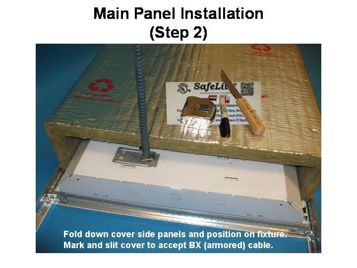
2 SafeLite Installation Instructions Fluorescent Fixtures (Refer to Diagrams) 1) For existing ceiling applications, remove ceiling tile from both sides and ends of the light fixture to aid installation otherwise skip to step 2. 2) Install the Peel N Stick pins on a clean fixture top, approximately 6 from each end of a 2 x 4 light fixture or one pin about centered for a 2 x 2 fixture. (See Fig. 3 below) Note: Position Peel N Stick pins away from the light fixture ballast location. 3) Slide SafeLite through ceiling grid and position over the fixture with main panel foil side up. 4) Fold side panels down to create a 3 sided box. (Fig. 2) 5) Position SafeLite square over the fixture aligning the end of the cover with the end of the fixture and carefully impale onto the mounting pin(s) tucking the side panels along the grid on both sides of the fixture. (Fig. 4) 6) Carefully slit the SafeLite cover to accommodate grid system, fixture support wires and power cable as needed to install cover. 7) Carefully push insulation lock washer(s) down over mounting pin(s) and snip off excess to prevent injury. (Fig. 5) 8) Position end caps against SafeLite, foil side out, flush with the cover top and edges and secure to cover top panel using steel push pin or alternate spiral wire anchor at the center. Finish securing the end cap panel ends to the side main cover panel edge with additional steel pins or spiral anchors evenly spaced. (Fig. 7) Note: If shown in the UL design listing for vented fixtures, carefully cut in ventilation openings consistent with the specific fixture design details. 9) Replace ceiling tiles that were removed during installation. dal 9/13
3 SafeLite Installation Instructions Can Light Fixtures (Refer to Diagrams Below) 1) For existing ceiling applications, remove ceiling tile from both sides and ends of the light fixture to aid installation otherwise skip to step 2. Note: Peel N Stick pins are not required for can light applications and are not included in the kit. 2) Slide SafeLite through ceiling grid and position over the fixture with main panel foil side up. 3) Fold side panels down to create a 3 sided box. (Fig. 2) 4) Position SafeLite square over the fixture aligning the end of the cover with the end of the fixture, Slit cover panels as necessary to slip over fixture mounting struts. 5) Carefully slit the SafeLite cover to accommodate grid system wires and power cable as needed to install cover and pull wires into cover. 6) Position end caps against SafeLite, foil side out, flush with the cover top and edges and secure to cover top panel using steel push pin or alternate spiral wire anchor at the center. Finish securing the end cap panel ends to the side panel edge with additional steel pins or spiral anchors evenly spaced. (Fig. 7) Note: If shown in the UL design for vented fixtures, carefully cut in ventilation openings consistent with the specific fixture design listings. 7) Replace ceiling tiles that were removed during installation. dal 9/13
4 SafeLite Installation Diagrams Fig. 1 SafeLite main panel cover. Dashed lines represent V groove mitered corners. Fig. 2 SafeLite main panel with side panels folded down.
5 Fig. 3 End flaps folded back in position over light fixture. Mark and carefully slit for hanger wires and power cable as needed. Note: Peel N Stick pins (2) applied to diagonal corners of a typical 2 x 4 light fixture or (1) approx. center of a 2 x 2 fixture. Do not place pins over light ballast. Note: Peel N Stick Pins are not required for can light fixtures
6 Fig. 4 SafeLite in position on fixture with panels tucked along grid and lock washer(s) secured to fixture anchor pin(s). Fig. 5 Section detail of offset anchor pin, fixture airspace and lock washer. Snip off any excess pin to prevent injury. Note: Figure 8 details alternate spacer pin.

7 Fig. 6 Detail of offset peel and stick anchor pin and lock washer. Note: Snip off excess pin length to prevent injury (See Fig. 8 for Alt. spacer clip detail). Fig. 7 Completed installation with end caps installed using 4.5 steel pins or spiral wire anchors spaced as shown. Note: check the specific UL listing for fixture ventilation opening requirements and carefully cut in as appropriate. Alternate: Spiral wire anchor (for end cap fastening)
8 Fig. 8 As an alternate to the offset spacer pin a steel V spacer clip is slipped over a straight stick pin replacing the offset pin to maintain typical 1 airspace.
INTERIOR INSTALLATION
 HOOK ON CROSS CONNECTOR CLAMP AT ALL INTERSECTIONS OF S 4-1 4" PANEL 1/2" x 1-1/2" 16 GA CR CHANNEL PRIMARY AT 48" O.C. MAX SPACING, TYPICAL. PANEL 1 1 2 " 12 GA HANGER WIRE, BY OTHERS, NOT BY HUNTER DOUGLAS.
MEDIA LED. Pendant Standard Mount Installation ou de montage WARNING:
 MEDIA LED Pendant Standard Mount WARNING: Disconnect main power at the source prior to installation! Thread gripper base onto 1 /4 20 stud, or with #8 screw. Depress gripper nozzle to insert aircraft cable.
INSTALLATION INSTRUCTION W Track Recessed 120V Flangeless
 W Track Recessed 120V Flangeless WT4-RTL, WT8-RTL, WT12-RTL SAFETY INSTRUCTION Read all of these instructions before installing the track system. Turn off power at main switch before installing or modifying
Acoustical. Pages Watch for this icon for compatibility with new taller grid profile. Ph:
 Watch for this icon for compatibility with new taller grid profile Pages 175-190 Sold by: http://www.twacomm.com Toll Free: (877) 892-2666 175 Lay In And Troffer Light Fixture Support Clips The original
AEM Intake Tube & Dryflow Air Filter Kit GT
 AEM Intake Tube & Dryflow Air Filter Kit 2011-2014 GT Time Required: Approximately 1 hour Tools Required: Pair of Diagonal Cutters or Tin Snip Pliers (something to cut thick wire) Medium Size Flat Head
ASSEMBLY INSTRUCTIONS
 A Canopy Assembly and wired by Licensed Electrician 1. Fixture Stud must be affixed to Electrical Box 2. Insert Nipple into Hickey 3. Slide Glass Canopy onto Nipple and secure with Hanger Loop with Washer.
INSTALLATION INSTRUCTIONS
 INSTALLATION INSTRUCTIONS Commercial Supplemental Instructions (For use with Commercial & Industrial Sectional Doors Installation & Maintenance Manual) Things to Know Before You Begin This is a supplement
TerraScreen Interior Greenwall System Field Installation Instructions (TW-4949 and TW-7049 Wall Mount)
") TerraScreen Interior Greenwall System Field Installation Instructions (TW-4949 and TW-7049 Wall Mount) This instruction is a guide to installing the TerraScreen Interior Greenwall System on a wall or support
TerraScreen Interior Greenwall System Field Installation Instructions (TW-4949 and TW-7049 Wall Mount) This instruction is a guide to installing the TerraScreen Interior Greenwall System on a wall or support
COYOTE Dome Closure 9.5" x 28" with Transition Tray for High Density Splice Applications
 OCTOBER 2017 COYOTE Dome Closure 9.5" x 28" with Transition Tray for High Density Splice Applications Be sure to read and completely understand this procedure before applying product. Be sure to select
Luminaire Support Location Cable Mounting Kit. Non-Power Feed
 INSTALLATION INSTRUCTIONS These installation instructions are used for installing the following luminaires and kits: Luminaire Support Location Cable Mounting Kit OLE4 (suspended) Normal Power Feed Non-Power
12 GA HANGER WIRE, BY OTHERS, NOT BY HUNTER DOUGLAS SEE DETAIL A1.1 MAIN RUNNER SPLICE. SPECIFICATIONS (unless noted otherwise)
") 12 GA HANGER WIRE, BY OTHERS, NOT BY HUNTER DOUGLAS SEE DETAIL A1.1 4' OPEN CELL RUNNER SEE DETAIL A1.7 FOR INFILL PANEL FIXTURE OPENING RECOMMENDATIONS CROSS RUNNER FIELD CUT AT PERIMETER TYPICAL SYSTEM
12 GA HANGER WIRE, BY OTHERS, NOT BY HUNTER DOUGLAS SEE DETAIL A1.1 4' OPEN CELL RUNNER SEE DETAIL A1.7 FOR INFILL PANEL FIXTURE OPENING RECOMMENDATIONS CROSS RUNNER FIELD CUT AT PERIMETER TYPICAL SYSTEM
Wall/Slot -II 85N Recessed Perimeter
 Type: Project: Wall/Slot -II 85N Recessed Perimeter Specifications 10 1/2 (267 ± 19) 9" (229) baffle shown in flush F/position 3 5/8" (92) FIXTURE SUPPORT RAIL. Extruded white aluminum, wall-mounted rail
DETAIL 'A' INTERIOR INSTALLATION. OVERALL ISOMETRIC VIEW (unless noted otherwise) 300C CARRIER 12 GA HANGER WIRE, BY OTHERS, NOT BY HUNTER DOUGLAS
 300C CARRIER 12 GA HANGER WIRE, BY OTHERS, NOT BY HUNTER DOUGLAS") 3 " NOM. 316 G, ER V RO N HA. TYP SEE DETAILS A1.7 THROUGH A1.10 FOR FIXTURE OPENING RECOMMENDATIONS IE ARR XC 12 GA HANGER WIRE, BY OTHERS, NOT BY HUNTER DOUGLAS SEE DETAIL A1.2 A "M 1'-0 300C PANEL SPLICE
3 " NOM. 316 G, ER V RO N HA. TYP SEE DETAILS A1.7 THROUGH A1.10 FOR FIXTURE OPENING RECOMMENDATIONS IE ARR XC 12 GA HANGER WIRE, BY OTHERS, NOT BY HUNTER DOUGLAS SEE DETAIL A1.2 A "M 1'-0 300C PANEL SPLICE
Thirteen (13) UL listed fluorescent fixtures per booth will supply illumination.
 UL listed fluorescent fixtures per booth will supply illumination.") Quoted as per your request: two (2) Non-Pressurized, Drive-Thru, Full Down Draft, Paint Booth model: TDD-16-16-20-DT with interior working dimensions of 16-0 wide X 16-0 tall X 20-0 long. Overall dimensions
Quoted as per your request: two (2) Non-Pressurized, Drive-Thru, Full Down Draft, Paint Booth model: TDD-16-16-20-DT with interior working dimensions of 16-0 wide X 16-0 tall X 20-0 long. Overall dimensions
SLiC Aerial Terminal and Spiral End Seal for use with AMP* Quiet Front Terminal Blocks
 SLiC Aerial Terminal and Spiral End Seal for use with AMP* Quiet Front Terminal Blocks Instructions June 2002 78-8130-2161-1-B 1 Contents: 1.0 General... 3 2.0 Kit Contents... 3 3.0 Cable Preparation...
Gasfire Flue Kits. B Vent Gas Flue Kit - Metallic Black (galvanised)
") Gasfire Flue Kits Product Description Part Number B Vent Gas Flue Kit - Metallic Black 588649 (galvanised) Geneva (Ultimate) This kit contains: Gas Cowl, Top Spider, Slip Liner 400mm, Outer Liner 1200mm,
Gasfire Flue Kits Product Description Part Number B Vent Gas Flue Kit - Metallic Black 588649 (galvanised) Geneva (Ultimate) This kit contains: Gas Cowl, Top Spider, Slip Liner 400mm, Outer Liner 1200mm,
INSTALLATION INSTRUCTION W Track Suspension system
 SAFETY INSTRUCTIONS: - Suspension mounting system should be installed by a qualified electrician only. - System is intended for installation in accordance with National Electric Code, local and - Federal
One Circuit Trac System TRAC SECTION, JOINERS & FEEDS T Series
 Project: Fixture Type: Location: Contact/Phone: PRODUCT DESCRIPTION DIMENSIONS Low-Profile, single-circuit trac sections for surface or pendant mounting. I-beam cross section provides added strength and
CHAPTER 15 FURNISHINGS. Section Title Page
 CHAPTER 15 FURNISHINGS Section Title Page 15.000 Description..................................... 15.1 15.100 Seat Harnesses................................... 15.3 15.110 Four-Point Harness Assembly.................
600 SERIES STANDARD DUTY STRAIGHT TRACK INSTALLATION INSTRUCTIONS
 600 SERIES STANDARD DUTY STRAIGHT TRACK INSTALLATION INSTRUCTIONS PLEASE READ INSTRUCTIONS THOROUGHLY BEFORE BEGINNING. A. BI-PARTING TRAVEL 1. Before raising track into position, determine location of
INSTALLATION INSTRUCTIONS ModuSys LED Retrofit Kit 2x2, rev. D.02
 INSTALLATION INSTRUCTIONS ModuSys LED Retrofit Kit 2x2, rev. D.02 Important safety information - read all instructions before installation. WARNING Risk of fire or electric shock. Luminaire wiring and
Be sure to read and completely understand this procedure before applying product. Be sure to select the proper PREFORMED product before application.
 5 NOVEMBER 2010 COYOTE Dome 9.5 x 28 Be sure to read and completely understand this procedure before applying product. Be sure to select the proper PREFORMED product before application. 1. 7. 2. 4. 10.
E E VDC COOLEDGE TILE INTERIOR INSTALLATION INSTRUCTIONS. Caution: Observe precautions for handling electrostatic sensitive devices.
 5 YEAR WARRANTY 5 YEAR WARRANTY COOLEDGE TILE INTERIOR INSTALLATION INSTRUCTIONS E354088 LISTED AC E354088 58VDC E354088 E354088 5 5 YEAR WARRANTY 5 YEAR WARRANTY E354088 Caution: Observe precautions for
INSTALLATION & OWNER S MANUAL
 INSTALLATION & OWNER S MANUAL CAB INSTALLATION INSTRUCTIONS FOR E-Z-GO MPT BALL CAGE (p/n 72685-G01) The contents of this envelope are the property of the owner. Be sure to leave with the owner when installation
LHBIP LED High Bay High Performance
 LED High Bay High Performance APPLICATION The LHBIP LED is a high efficiency I-Beam style high bay fixture engineered for premium performance. A precision-formed silver reflector is designed to achieve
MAZDA CX on OUR REF: H0682
 MAZDA CX-5-2017 on OUR REF: H0682 PACKAGING REQUIREMENTS. BOOT LINER 2 x 390 mm 30mm wide selfadhesive loop fastener 11 x tabs self-adhesive loop fastener 12 x (ref.113)tabs Frequent use hook & loop fastener
F. VAV hoods shall have a restricted bypass plate.
 1.01 SUMMARY A. Section Includes: 1. Laboratory fume hoods. B. Related Sections: 1. Section 6500 Laboratory casework 2. Section 15 Mechanical: Furnishing and installation of plumbing utilities and final
X5 / X6 N63 Upgrade Intercooler Installation Instructions
 X5 / X6 N63 Upgrade Intercooler Installation Instructions Part Number: D330-0016 Applications: 2010-12 E70 X5 xdrive 50i 2008-12 E71 X6 xdrive 50i PARTS LIST Qty Part No. Description 2 11 78 7 549 563
UT ASSEMBLY REQUIREMENTS. *Torque all T-bolt nuts to foot pounds.
 UT-1200-16-04 ASSEMBLY REQUIREMENTS *Torque all T-bolt nuts to 35-40 foot pounds. *Check all lights before towing. *Tire pressure not to exceed recommendation on serial tag. *Re-torque wheel nuts after
General Installation Instructions LED
 General Installation Instructions LED To reduce the risk of death, personal injury or property damage from fire, electric shock, falling parts, cuts/abrasions and other hazards, please read all warnings
Hinges and Flap Fittings Furniture Hinges
 Butt hinge Material: Steel Length: 50 mm Flange thickness: 1.5 mm Barrel Ø: 8 mm Crank A, straight Ø Gap1 mm Mounting Nickel plated matt Left 1.08.717 Right 1.08.708 Brass plated Left 1.08.511 Right 1.08.502
One Circuit Trac System TRAC SECTION, JOINERS & FEEDS T Series
 Project: Fixture Type: Location: Contact/Phone: PRODUCT DESCRIPTION DIMENSIONS Low-Profile, single-circuit trac sections for surface or pendant mounting. I-beam cross section provides added strength and
Roller Shades MOTORIZED SHADE. Simplicity. Installation & Care Instructions
 Roller Shades MOTORIZED SHADE Simplicity Installation & Care Instructions 152140 I 8/12/2015 GETTING STARTED A few simple tools are required: - Measuring tape - Power drill, drill bits - 1 4 Hex head and/or
Roller Shades MOTORIZED SHADE. Simplicity. Installation & Care Instructions
 Roller Shades MOTORIZED SHADE Simplicity Installation & Care Instructions 152140 J 1/13/2016 GETTING STARTED A few simple tools are required: - Measuring tape - Power drill, drill bits - 1 4 Hex head and/or
Installation Instructions Supertop for Truck
 Installation Instructions Supertop for Truck US Patent 6827391 Vehicle Application: Ford F150 1987-1996 (8 ft.) Part Number: 76315 Ford F250 1987-1998 (8 ft.) Part Number: 76315 Ford F350 1987-1998 (8
INSTALLATION OF THE ENCLOSURE FOR THE MULE 3010 TRANS INSTALLATION GUIDE FOR THE MULE 3000 TRANS ENCLOSURE P. 1. Sept 07
 INSTALLATION GUIDE FOR THE MULE 3000 TRANS ENCLOSURE P. 1 INSTALLATION OF THE ENCLOSURE FOR THE MULE 3010 TRANS Sept 07 www.essexmfg.com PO Box 92864 Southlake, TX 76092 Ph:888-643-7739 INSTALLATION GUIDE
How to fold your MGB top (pre 1970 pack away top & frame)
") How to fold your MGB top (pre 1970 pack away top & frame) It is most important that the instructions given for raising, lowering and folding the hood are followed. Do not use undue force on the hood frame-members.
How to fold your MGB top (pre 1970 pack away top & frame) It is most important that the instructions given for raising, lowering and folding the hood are followed. Do not use undue force on the hood frame-members.
R O A D S M I T H TRIKE CONVERSIONS BY THE TRIKE SHOP
 R O A D S M I T H TRIKE CONVERSIONS BY THE TRIKE SHOP Please thoroughly review the instructions before and during installation. Keep in mind that this product was designed to be installed by trained dealer
Estimated Cable Fill Width in (mm) in 2 mm 2.30 OD. Cable Fill Area
 in 2 mm 2.30 OD. Cable Fill Area") ONTRAC WIRE MESH CABLE TRAY SYSTEM OnTrac Wire Mesh Cable Tray System CPI s OnTrac Wire Mesh Cable Tray System is an excellent solution for indoor cable pathway applications to create point-to-point pathways
ONTRAC WIRE MESH CABLE TRAY SYSTEM OnTrac Wire Mesh Cable Tray System CPI s OnTrac Wire Mesh Cable Tray System is an excellent solution for indoor cable pathway applications to create point-to-point pathways
DODGE SLT Installation Instructions
 1994-97 DODGE SLT 40-20-40 Installation Instructions Step 1. Driver and Passenger Bottoms/DB&PB: All the parts of the seat cover are labeled inside. Use the seat cover piece identification chart to ID
Two Circuit Trac System TRAC SECTION, JOINERS & FEEDS
 Project: Fixture Type: Location: Contact/Phone: PRODUCT DESCRIPTION DIMENSIONS Low profile, two-circuit trac sections for surface or pendant mounting. Provides two separate 20-amp circuits from a single
Lighting Systems Argus-7
 Page 1 of 5 1 1. (3.5cm) 1.7 (4.3cm) 4 5 Rectilinear 3 1.81 (4.6cm) Extruded Linear Louver.5 (.64cm) 5. (1.7cm) 9. (.86cm) 1 1. (3.5cm) 1.7 (4.3cm) 4 5 Tapered 3 1.81 (4.6cm).75 (.7cm) Feature Specifications
Installation Instructions
 Installation Instructions Models: SLP Venting System These venting system components have been tested for use with approved HHT Direct Vent appliances. Check with your local building code agency before
564 Shadowbox Face (w Screen) Instructions
 Instructions") Packing List Compatibility Face Bottom Shield (2) Face Brackets (8) Screws (#8 x 3/8 Phillips) (5) Screws (#8 x 5/8 hex head) Drill Template 11/64 Drill Bit Items Used with Optional Switch Box (see note
Packing List Compatibility Face Bottom Shield (2) Face Brackets (8) Screws (#8 x 3/8 Phillips) (5) Screws (#8 x 5/8 hex head) Drill Template 11/64 Drill Bit Items Used with Optional Switch Box (see note
Easy as QUICK REFERENCE SLOPE GUIDE CHART
 QUICK REFERENCE SLOPE GUIDE CHART Easy as Step #1 - Measure the rise of your application. Step #2 - Determine your maximum slope.* Step #3 - Pick the proper ramp length, based on your selections, in the
3 Turbo Downpipe Installation Audi A3 / Volkswagen GTI / Volkswagen Jetta 2.0L FSI/TSI Turbo CD100013
 Please take time to read and understand these installation instructions. APR recommends that installation of this system be performed by a qualified service center or professional muffler installer who
Installation Instructions Table of Contents
 Installation Instructions Table of Contents Pre- Installation of Garage Storage Lift 2 Layout the Garage Storage Lift 3 Installing the strut Channels 3 Install the Drive Assembly 5 Install the Drive Shaft
INTERIOR > CONSOLE, FLOOR > REMOVAL > REMOVAL > BASE FLOOR CONSOLE
 Page 1 of 18 2016 Dodge Grand Caravan 3.6L Eng VIN G SE Service Manual: BODY - INTERIOR & EXTERIOR Print Date: INTERIOR > CONSOLE, FLOOR > REMOVAL > REMOVAL > BASE FLOOR CONSOLE Fig 1: Base Floor Console
Equipped with AEM Dryflow Filter No Oil Required! INSTALLATION INSTRUCTIONS PART NUMBER: C
 Equipped with AEM Dryflow Filter No Oil Required! INSTALLATION INSTRUCTIONS PART NUMBER: 21-721C 2011-2013 MINI Cooper S L4-1.6L SEE NOTE* 2011-2013 MINI Clubman S L4-1.6L SEE NOTE* 2011-2013 MINI Cooper
ECO-T LED RECESSED TROFFER USER MANUAL
 ECO-T LED RECESSED TROFFER USER MANUAL INSTALLATION GUIDE FOR: 2X2: MLRT22D4535 MLRT22D4541 MLRT22D4550 2X4: MLRT24D5535 MLRT24D5541 MLRT24D5550 Thank you for purchasing this MaxLite product. For additional
Installation Instructions Cable Top Twill Replace-a-top with Tinted Windows Upper Door Skins not included
 Installation Instructions Cable Top Twill Replace-a-top with Tinted Windows Upper Door Skins not included Vehicle Application Jeep Wrangler (JK) 2 Door 2011 and newer Part Number: 79846 Will fi t 54722
53-40 ATTACH FITTINGS
 ATTACH FITTINGS. DESCRIPTION Attach fittings are provided for attachment of the seats (Refer to -0), baggage straps (Refer to -0), rear seat harnesses (Refer to -0), cargo net straps (Refer to -0), cabin
F Ext Cab 40/20/40 w/ integral seatbelt Installation
 2001-07 F-250-350 Ext Cab 40/20/40 w/ integral seatbelt Installation Step 1. Driver and Passenger Tops/DT & PT: Temporarily remove the headrests by lifting them up all the way. Then with slight upward
Section 3. Custom. Recessed
 Section 3 Custom Recessed BX Connector 13.375" 11.375" Hanging Cable Typ (By others) Threaded Rod Typ (By others) 23.375" OAL Fixture Lamp Housing PAR30 Lamp Holder Ballast Compartment 6.781" 45 " 12.000"
Installation Instructions for TLC79DCA Toyota Landcruiser VDJ79 Series 90lt Auxiliary Tank
 Installation Instructions for TLC79DCA Toyota Landcruiser VDJ79 Series 90lt Auxiliary Tank 1. Carry out wiring of PG200 switch gauge unit, suggested switch location is in the large rectangle blank on the
HR-led418-n Invisible Trim
 HR-led418-n Invisible Trim 4" LEDme Non-IC New Construction Housing 52 22 3w Fixture Type: 3d min 15 max 242 Catalog Number: Project: 6w Location: Product Description 4 inch LEDme Invisible Trim Non-IC
2.5 & 4.5 Rear Coil Spring & 2.5 Spacer Kits. Dodge 2500 Pickup Part#: , ,
 Part#: 012259, 012258, 012458 2.5 & 4.5 Rear Coil Spring & 2.5 Spacer Kits Dodge 2500 Pickup 2014 Rev. 040915 491 W. Garfield Ave., Coldwater, MI 49036. Phone: 517-279-2135 Web/live chat: www.bds-suspension.com.
Idaho Profile System - Trimless
 3 4/16 82mm DIRECT 3 9/16 90mm 3 6/16 85mm L3ID-TRI-SYS DR OP Article # Distribution Diffuser Length Voltage Linear Electrical Mounting Brackets Lighting Control Product Distribution Diffuser Length Voltage
Page: REV 3: Add drill and tap information to Figure 4 DRILL #3, TAP 1/4-28 BOTH ENDS.
 REVISION DESCRIPTION: 1) Page: 32-03 MEMO: Step 4 should not be bold. Fix WD-1213 callout in Figure 3. Page: 32-04 REV 3: Add drill and tap information to Figure 4 DRILL #3, TAP 1/4-28 BOTH ENDS. Add make
COLD AIR INTAKE INSTALLATION INSTRUCTIONS. # D Fits: F10 M5 # D Fits: F06/F12/F13 M6 PARTS LIST
 COLD AIR INTAKE INSTALLATION INSTRUCTIONS # D760-0035 Fits: 2013-15 F10 M5 # D760-0037 Fits: 2012-15 F06/F12/F13 M6 PARTS LIST (1) Left Carbon Airbox Lid (1) Right Carbon Airbox Lid (1) Left Carbon Snorkel
IMPORTANT SAFETY INSTRUCTIONS
 INSTALLATION INSTRUCTIONS READ ALL OF THESE INSTALLATION INSTRUCTIONS BEFORE INSTALLING THE TRACK SYSTEM SAVE THESE INSTRUCTIONS AND REFER TO THEM WHEN ADDITIONS TO OR CHANGES IN THE TRACK CONFIGURATION
Plaster Flange Flangeless. Donn Fineline Armstrong Bolt. Flange (All Ceilings)
") & TM VersaLux ARCHITECTURAL LIGHTING SERIES Fluorescent Slot Fluorescent Slot, Flush Lens Ceiling/Trim Options Plaster less Drywall Fellert (All Ceilings) Donn Fineline Armstrong Bolt TechZone 9/16 Superfine
& TM VersaLux ARCHITECTURAL LIGHTING SERIES Fluorescent Slot Fluorescent Slot, Flush Lens Ceiling/Trim Options Plaster less Drywall Fellert (All Ceilings) Donn Fineline Armstrong Bolt TechZone 9/16 Superfine
RS696PXYQ1 (BLACK) (DESIGNER WHITE)
 (DESIGNER WHITE)") OVEN PARTS 12 92 Litho in U.S.A. 2 Part. No. OVEN PARTS NOTE: The screws and nuts required to attach a part are listed immediately following that part. 1 3176698 Frame, Front 2 307985 Pin, Hinge Ear (2)
OVEN PARTS 12 92 Litho in U.S.A. 2 Part. No. OVEN PARTS NOTE: The screws and nuts required to attach a part are listed immediately following that part. 1 3176698 Frame, Front 2 307985 Pin, Hinge Ear (2)
The GK units differ from the LK units in that the springs of the GK units have a spring eye at the front.
 01 09 Installation guidelines Mechanical suspension units GK LK GN0032-0 Mechanical suspension units GK LK The GK units differ from the LK units in that the springs of the GK units have a spring eye at
Electrical Applications. Metal Framing & Cable Tray Superstrut Metal Framing System. Column A. Design Data: Materials: Column B
 Electrical Raceway Series 800 Surface Raceway and Lighting Systems Superstrut channel together with snap-in closure strip is listed by Underwriters Laboratories as a surface metal raceway. Other accessories
Air terminal devices
 Installation manual GB/en Air terminal devices Slot Diffusers Type PureLine18 TROX GmbH Heinrich-Trox-Platz 47504 Neukirchen-Vluyn Germany Phone: +49 (0) 2845 2020 Fax: +49 (0) 2845 202265 E-mail: trox@trox.de
Installation Instructions
 Installation Instructions TrailView Soft Top Important Safety Information For proper installation and best possible fit, please read all instructions BEFORE you begin. Periodically check all components
Installation Instructions Supertop NX Twill
 Installation Instructions Supertop NX Twill Vehicle Application: Jeep Wrangler Unlimited 2007-current Part Number 54823 Installation Tips Before you begin installing your new Supertop NX Twill, please
ROOF SAFETY ACCESSORIES
 ROOF SAFETY ACCESSORIES Page Ridge- / Eave Railing and Eye Hook for Life Line 130-131 Snow Guards 132-133 Roof Gangways 134-135 Safety Railing 136 Roof Access Ladders 137 Roof Access Treads 138 Villa Roof
Assembly of kick TM Utility Poles
 Assembly of kick TM Utility Poles #2 Phillips screwdriver 3/16" Ball-End Allen Bit with 6" Extension WARNING: If you have a problem, question, or request, call your local dealer, or Steelcase Line 1 at
Avenue B. Grid Mount (Regress Trim Shown) Flush Lens. Drywall Flange (Regress Trim Shown) Narrow 3" slot LED with frosted satin lens.
 Flush Lens. Drywall Flange (Regress Trim Shown) Narrow 3 slot LED with frosted satin lens.") LED corrugated regress trim solid regress trim flush lens DIMENSIONAL DATA Grid Mount (Regress Trim Shown) FEATURES Narrow 3" slot LED with frosted satin lens. Shielding options include corrugated or solid
LED corrugated regress trim solid regress trim flush lens DIMENSIONAL DATA Grid Mount (Regress Trim Shown) FEATURES Narrow 3" slot LED with frosted satin lens. Shielding options include corrugated or solid
Installation Instruction
 T F W 604.549.9379 604.549.9555 fluxwerx.com Installation Instruction DRIVER ENCLOSURE Ceiling Type Version Grid Battery Pack GRID MOUNT INSTALL OPTIONS OPTION 1: Standard Vertical Grid drivers can be
1.6 Accessories include tool-free snap-in technology options for air flow, cable management, shelves, power distribution units, etc.
 Rittal TS IT Rack Guide Specifications TS IT network server enclosure 1.0 General Description 1.1 Modular Free Standing Equipment Cabinet 1.2 Various combinations of dimensions: 1.2.1 Height: 48 /1200mm,
Plaster Trim Flange Trim Trimless. for ceilings requiring a flange. Donn Fineline Armstrong Bolt
 & VersaLux ARCHITECTURAL LIGHTING SERIES Fluorescent Slot Fluorescent Slot, Flush Lens TM 3.6250" Ceiling/Trim Detail Plaster Trim Flange Trim Trimless Drywall Fellert for ceilings requiring a flange Donn
Dodge opening upper console w/non-opening middle bottom Installation
 2009-12 Dodge 40-20-40 opening upper console w/non-opening middle bottom Installation Step 1. Prepare the driver and passenger seat for installation by temporarily removing the headrests. Recline the backrests
Cold Air Intake Installation Instructions
 Page 1/5 3.04 INS262 BAVARIAN AUTOSPORT Cold Air Intake Installation Instructions NOTE: Throughout the instructions the term AFM is used. It refers to the Air Flow Meter which is located between the engine
Southwest Windpower Instruction Sheet AIR-X Circuit Replacement Kit
 Southwest Windpower Instruction Sheet AIR-X Circuit Replacement Kit Tools Required 5 / 32 Hex key 5 / 16 Hex key 7 / 64 Hex key Standard screwdriver Pair of external snap ring pliers Rubber mallet Hammer
INSTALLATION INSTRUCTIONS
 INSTALLATION INSTRUCTIONS --1075 North Ave. Sanger, CA 93657-3539 local: 559-875-0222 fax: 559-876-2259 toll free: 800-445-3767-- 2103 FRONT DROP BALL JOINT INSTALLATION INSTRUCTIONS CHEVY COLORADO Congratulations!
Installation Instructions I - Sheet Number I-TVR-01 Rev. A
 Installation Instructions I - Sheet Number I-TVR-01 Rev. A TrailView Soft Top For proper installation and best possible fit, please read all instructions BEFORE you begin. For technical assistance or to
Concealed hinges. Premium hinge systems for cabinet doors. blum.com
 Concealed hinges Premium hinge systems for cabinet doors blum.com Quick reference Simple planning and ordering lum offers many on-line tools to help you with your kitchen planning and ordering. Planning
underfloor 49 UFC UFC 50 FAS P 50 UFCN 51 UC C DF 54 UFS 55 UFFS 56 UFS Cablofil cable management UNDER FLOOR SUPPORT CLAMP kit
 underfloor 49 UFC 550 UNDER FLOOR SUPPORT CLAMP kit 49 UFC UNDER FLOOR SUPPORT CLAMP 50 FAS P FAS PROFILE 50 UFCN UNDER FLOOR CLAMP 51 UC 50 CABLE TRAY STANDOFF 51 C 50 UNDER FLOOR ATTACHMENT 52 fas l
Service Bulletin
 Service Bulletin 14-009 February 13, 2014 ATB 50862 (1402) Driver s Seat Heater Shuts Off After Turning On AFFECTED VEHICLES Year Model Trim VIN Range 2011 13 Odyssey EX-L, Touring ALL SYMPTOM The driver
argco.com
 800-854-1015 argco.com STRUT SUPORT SYSTEM STRUT SUPPORT CHANNEL US Strut Support Channel Quick, strong attachment of single or multiple pipes horizontally or vertically Unlimited applications - range
JANUARY 2015 NOMENCLATURE. TOOLS REQUIRED 3/8" & 7/16" Can wrench or socket 1/4 Nut driver or screwdriver Snips Fiber optic cable opening tools
 JANUARY 2015 COYOTE Dome Closure 6-1/2" x 17" Be sure to read and completely understand this procedure before applying product. Be sure to select the proper PREFORMED TM product before application. 1 2
»Product» Safety Warning
 #F9387 Installation Instructions 1999-2003 Ford Super Duty 2/4wd Gas Only 3" Body Lift Kit Read and understand all instructions and warnings prior to installation of product and operation of vehicle. Zone
Wedgy Attachment Solutions
 Innovation Since 1977 Introduction - Table of Contents Designed and Engineered by Professionals for Professionals Labor Saving Attachment Solutions Wedgy Attachment Solutions STEEL METAL Wedgys work because
300 SERIES STANDARD DUTY CURVED TRACK
 300 SERIES STANDARD DUTY CURVED TRACK COMPLETE TRACK MODEL NUMBERS 301A 301W 316A 316W 328A 328W 300B SERIES BLACK CURVED TRACK COMPLETE TRACK MODEL NUMBERS 301AB 301WB 316AB 316WB 328AB 328WB SINGLE CARRIER
COYOTE Dome Closure 6.5" x 22" Kits. COYOTE Dome Closure 6.5" x 22" for Buffer Tube Applications. Includes: (2) Grommets, (1) Buffer
 Grommets, (1) Buffer") JANUARY 2015 COYOTE Dome Closure 6.5" x 22" Be sure to read and completely understand this procedure before applying product. Be sure to select the proper PREFORMED product before application. 1 2 3 6
JANUARY 2015 COYOTE Dome Closure 6.5" x 22" Be sure to read and completely understand this procedure before applying product. Be sure to select the proper PREFORMED product before application. 1 2 3 6
The world's first Bolt in Only stress bar for VW Mk 4 Chassis. Installation Manual V1.0.
 The world's first Bolt in Only stress bar for VW Mk 4 Chassis Installation Manual V1.0 www.yarrowsport.com Tools Needed: 1. 17mm, 10mm sockets and ratchet with 3inch extension 2. 10mm box end wrench 3.
Installation Instructions Supertop for Truck
 Installation Instructions Supertop for Truck US Patent 6827391 Vehicle Application: Toyota Tacoma Double Cab 2005-2011 (5 ft.) Part Number: 76308 INSTALLATION TIME SKILL LEVEL 1-1/2 Hours 2 - Moderately
R. STAHL Schaltgeräte GmbH Geschäftsbereich Leuchten Nordstraße Weimar, Germany
 ECOLUX 6608 Series 6608/5 Explosion Protected Fluorescent Emergency Light Fixtures for Hazardous and Corrosive Applications Please read this entire document before beginning any work. 1. Safety Instructions
TerraScreen Interior Greenwall System Field Installation Instructions (TW-4949 and TW-7049 Free-Standing)
") TerraScreen Interior Greenwall System Field Installation Instructions (TW-4949 and TW-7049 Free-Standing) This instruction is a guide to installing the TerraScreen Interior Greenwall System on the free-standing
TerraScreen Interior Greenwall System Field Installation Instructions (TW-4949 and TW-7049 Free-Standing) This instruction is a guide to installing the TerraScreen Interior Greenwall System on the free-standing
1Unpack fixture. Suspensions/canopies are ordered and
 DO NOT REMOVE THE LED ASSEMBLY. THIS WILL VOID THE WARRANTY. Call Zumtobel at 1-800-448-4131 questions. Fixture is intended installation in accordance with bee servicing. Retain these instructions 2Determine
CFP-LED Contractor Select Flat Panel. Installation Instructions
 IMPORTANT SAFETY INSTRUCTIONS To reduce the risk of death, personal injury or property damage from fire, electric shock, falling parts, cuts/abrasions, and other hazards please read all warnings and instructions
INSTALLATION GUIDE Front Bumper. KL Cherokee (Trailhawk)
") INSTALLATION GUIDE Front Bumper KL Cherokee (Trailhawk) Included Hardware: Sample Sample Sample Skill Level: 5/5 stars (Professional install recommended) Disclaimer Expedition One is not responsible for
INSTALLATION GUIDE Front Bumper KL Cherokee (Trailhawk) Included Hardware: Sample Sample Sample Skill Level: 5/5 stars (Professional install recommended) Disclaimer Expedition One is not responsible for
COLD AIR INTAKE INSTALLATION INSTRUCTIONS
 COLD AIR INTAKE INSTALLATION INSTRUCTIONS # D760-0033 Fits: 2013-15 F01 B7, 750i & xdrive (N63TU engine) 2013-15 F02 B7L, 750Li & xdrive (N63TU engine) PARTS LIST Left and right carbon fiber air box lids
TOYOTA VENZA 2009 TRAILER WIRE HARNESS Procedure
 Part Number: PT791-0T099 Kit Contents Item # Quantity Reqd. Description 1 1 Trailer Wire Harness Module 2 1 4-Flat Harness 3 1 Battery Power Wire Harness 4 1 Mounting Bracket, 4-Flat 5 2 Screw #10-24 6
Improved Fire Protection Retro-Fit Manual for US LSA Airplanes Fire Wall Protecting
 THIS DOCUMENT AND THE TECHNICAL DATA HEREON DISCLOSED ARE PROPRIETARY TO AND SHALL NOT BE USED, RELEASED, OR DISCLOSED IN WHOLE OR IN PART WITHOUT EXPRESS WRITTEN PERMISSION FROM Page: 2 Table of Contents
Please try our way first.
 1958-1962 Corvette Raingear installation instructions Designer s Note: The 1958-1962 Corvette RainGear wiper system that you have purchased is complex and will require patient fitting. Complete Instructions
COYOTE 28" GLC (Ground Level Closure) Complete Assembly Installation
 Complete Assembly Installation") NOVEMBER 2016 COYOTE 28" GLC (Ground Level Closure) Complete Assembly Installation Be sure to read and completely understand this procedure before applying product. Be sure to select the proper PREFORMED
NOVEMBER 2016 COYOTE 28" GLC (Ground Level Closure) Complete Assembly Installation Be sure to read and completely understand this procedure before applying product. Be sure to select the proper PREFORMED