Paxton. ins us. Paxlock US
|
|
|
- Anissa York
- 5 years ago
- Views:
Transcription
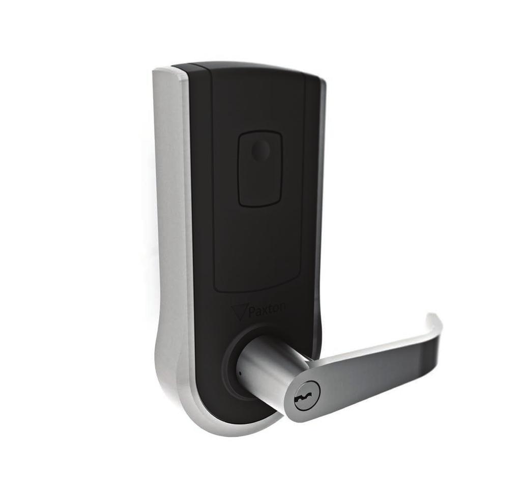

1 Paxton ins us Paxlock US
2 ? 3 5 2* * x 2 X 3 x 2 What s in the box 1) Front handle 2) Lock Cylinder * 3) Paxlock front housing 4) Motor adjustment plate 5) Motor 6) Latch 7) Latch screws x 2 8) Motor backplate 9) Backplate/Rose assembly 10) Paxlock rear housing 11) 4 x AA Alkaline batteries 12) Rear battery cover 13) Rear handle cover 14) Rear Handle 15) Small mounting screws x 2 16) Long mounting screws x 3 17) Battery cover key 18) Handle removal pin 19) Keys x 2 * 20) Handle washers x 2 21) Strike plate 22) Strike plate screws x 2 * Not for SFIC Tools List Power Drill Drill bits (1, 5/16, 5/8, 1/8 ) Crosshead screwdriver Chisel 1 Knife Adhesive tape Pencil Tape measure 1
 backset 2 Step 2: Drilling To ensure accuracy you should drill holes from both sides of the door towards the center.")
3 1 Step 1: Marking out Tape template to door, mark holes then remove template for drilling. 2-3/8 (60mm) backset 2 Step 2: Drilling To ensure accuracy you should drill holes from both sides of the door towards the center. This avoids the risk of damaging the door face when the drill breaks through. 5/16 (8mm) 5/8 (16mm) Make sure to include pilot holes either side of the central hole to ensure flush fitting of the motor plates. 5/16 (8mm) 2-1/8 (54mm) 5/16 (8mm) 5/16 (8mm) 5/16 (8mm) For doors with a beveled leading edge, ensure that the backset is measured from the face of the latchbolt, ensuring the latchbolt will be installed square to the door face and not aligned to the bevel. This will ensure that the lockset is positioned correctly. 3 Step 3: Marking out and chiseling for latch To install the latch; drill a 1 (25mm) hole, slide in the latch, then draw around the faceplate. 1 (25mm) Width 3-1/4 (82mm) Depth Remove the latch and score the outline with a knife to avoid splitting the wood when chiselling. 2
4 4 Step 4: Fitting the door latch Attach the latch using the screws provided. 5 Step 5: Fitting the strike plate Close the door to mark the horizontal line of the strike plate. Measure one half of door thickness from door stop to mark vertical center line of the strike. Drill 1 (25.4mm) hole, 1/2 (12.7mm) deep at intersection of horizontal and vertical center lines. Cut out jamb 3/32 (2.4mm) deep or until the strike is flush with jamb. Tighten the strike plate screws securely. 6 Step 6: Inserting the motor Pass the motor through the central hole within the door, making sure to pass the motor lead through the hole first. 3
5 7-2 (50mm) - 1-3/4 (45mm) Step 7: Rotating the motor adjustment plate To ensure that the motor adjustment plate is at the correct distance, rotate until it sits flush with the door and the motor has engaged properly. Please refer to the diagram for the correct position of the plate for each door thickness. 8 Step 8: Ensuring the latch engages Make sure the tail of the latch is engaging with the motor retractor correctly as illustrated. 9 Step 9: Fitting the front housing Line up front housing and ensure the body is flush to the door. *PaxLock US is set up for RH doors by default please see page 8 for LH operation. 4
6 10 Step 10: Fitting the rear backplate assembly Feed the motor cable through the hole in the motor back plate. 11 Step 11: Fitting the rear housing and motor wiring Feed both the cables through the rear housing cutout and fit the lower long mounting screws. 12 Step 12: Fitting the rear lock assembly and wiring Fit top, long mounting screws and 2 lower short screws. 5
7 13 Step 10: Fitting the batteries 14 Step 11: Securing the rear cover 15 Step 12: Fitting the cover plate and handle 6
8 Optional step: Handle orientation for LH door To configure for LH door operation, remove the front and rear handles using the handle removal pin. Unscrew the 4 screws securing the rose to the front/rear housings, rotate 180 degrees and screw back together. Refit the handles, and push home until the axle engagement clicks. Optional step: Contact switch Optional step: Inserting the handle washers Handle feel can be tightened with the use of the included washers. 7


9 Software installation x1 200 x Net2 Pro/Net2 Lite: Wireless Signal Range 0 m 0 ft 3m 10ft 15m 50ft 20m 65ft 30m 100ft 8


10 Enrolling a PaxLock
11 PaxLock reset Battery replacement
12 Specifications Features Maximum number of users/tokens Access Levels Time zones Door unlock time Recommended number of Paxlock s per Net2Air bridge Net2Air bridge per system Net2Air wireless range Events stored HID functionality Environment Battery type Typical Battery life Operating temperature Moisture resistance External Use Vandal resistance Dimensions Total outside dimensions (includes handle clearance) Min Typ Max 1 sec 10, secs ft 3,584 Yes Min Max 4 x AA Alkaline 20,000 operations 30,000 operations 0 C (+32 F) +55 C (+131 F) IPX4 No Low Width Height Depth 6 8 1/2 3 UL has only evaluated the Operating temperature specification HID Activation To enable HID Prox 125 khz, simply present your activation card to the reader you wish to activate. The readers LED s will advise you of the success of the activation by displaying a green LED. Once the reader has indicated a successful activation, HID Prox 125 khz cards can then be added to the system via the desktop reader and used around the site. 11
 78485147 support@paxton-benelux.com paxton.benelux.support +49 (0) 251 2080 6900 verkauf@paxton-gmbh.")

13 +44 (0) paxton.support usapaxton.support +31 (0) paxton.benelux.support +32 (0) paxton.benelux.support +49 (0) paxton.gmbh.support +33 (0) paxton.support +27 (0) paxton.support paxton.support paxton.soporte paxton.soporte +44 (0) paxton.support 12
14 The declaration of conformity is available on request. Contact details are provided at: North America:- These products are not suitable for retail sale. All warranties are invalid if these products are not installed by a competent person. Product Compliance and limitations Wiring methods shall be in accordance with the National Electrical Code (ANSI/NFPA70), local codes, and the authorities having jurisdiction. To comply as a UL listed installation, the following conditions must apply:- Server based functions (Antipassback, Time and Attendance, etc) have not been evaluated by UL and cannot be used for UL 294 installations. Where an equivalent cable / wire is used it must be UL Listed All interconnecting devices must be UL Listed. The use of Wiegand readers and the configuration software has not been evaluated by UL Door contact connections are limited to a maximum of 30m. IP rating not verified by UL. Indoor use only UL listed to the following standards: ANSI/UL 10C compliant (20 min fire doors), CAN/ULC S104 compliant (20 min fire doors), UL 294 compliant, CSA C22.2 NO compliant FCC Compliance This device complies with Part 15 of the FCC Rules. Operation is subject to the following two conditions: (1) this device may not cause harmful interference, and (2) this device must accept any interference received, including interference that may cause undesired operation. Changes or modifications not expressly approved by the party responsible for compliance could void the user's authority to operate the equipment. The Paxlock US has been designed and complies with the safety requirements for portable (<20cm) RF exposure in accordance with FCC rule part and KDB D01 as demonstrated in the RF exposure analysis. Installers must ensure that this device must not be co-located or operated in conjunction with any other antenna or transmitter except in accordance with FCC multi-transmitter product procedures. IC Compliance This device complies with Industry Canada licence-exempt RSS standard(s). Operation is subject to the following two conditions: (1) this device may not cause interference, and (2) this device must accept any interference, including interference that may cause undesired operation of the device. The Paxlock US has been designed and complies with the safety requirements for RF exposure in accordance with RSS- 102 as demonstrated in the RF exposure analysis. 13
15 14
16 Made in the UK Paxton Ltd /03/2014
(SB2) (SB1) (SB3) (SB5) (SB4) Cylindrical Installation Instructions. A. CHECKLIST (4 each AA Batteries Included) (SB1) (SB4) (SB2) (SB6) (SB6) (SB3)
 (SB1) (SB3) (SB5) (SB4) Cylindrical Installation Instructions. A. CHECKLIST (4 each AA Batteries Included) (SB1) (SB4) (SB2) (SB6) (SB6) (SB3)") A. CHECKLIST (4 each AA Batteries Included) FOR DOOR AND FRAME PREPARATION INSTRUCTIONS, SEE APPENDIX A OR GO TO PROXESS.COM Parts List: Each Proxess C-Series lockset includes Exterior lock assembly (include
A. CHECKLIST (4 each AA Batteries Included) FOR DOOR AND FRAME PREPARATION INSTRUCTIONS, SEE APPENDIX A OR GO TO PROXESS.COM Parts List: Each Proxess C-Series lockset includes Exterior lock assembly (include
Installation Guide(s)
") FCC Part 15 Transmitter Certification Test Report FCC ID: SPI-4XXKPMR FCC Rule Part: 15.09 ACS Report Number: 05-070-15C Manufacturer: Single Access Lock Inc. Model: 4XXKP/MR Installation Guide(s) 5015
FCC Part 15 Transmitter Certification Test Report FCC ID: SPI-4XXKPMR FCC Rule Part: 15.09 ACS Report Number: 05-070-15C Manufacturer: Single Access Lock Inc. Model: 4XXKP/MR Installation Guide(s) 5015
CM5100 COMPUTER MANAGED CYLINDRICAL LOCK HARD-WIRED (FSE/FSA) INSTALLATION MANUAL
 INSTALLATION MANUAL") The 5100 series lock is a stand-alone, microprocessor controlled, electromechanical locking system. The 5100 employs a heavy-duty mechanical design which is easy to install and highly reliable. The FSE
The 5100 series lock is a stand-alone, microprocessor controlled, electromechanical locking system. The 5100 employs a heavy-duty mechanical design which is easy to install and highly reliable. The FSE
Installation Instructions RF4510-EA
 Installation Instructions RF4510-EA HES, Inc. 22630 N. 17th Ave. Phoenix, AZ 85027 800-626-7590 1 Product Description Dimensions Orientation Compatibility Access Control Systems Proximity Cards Frequency
Installation Instructions RF5010 and RF5210
 Installation Instructions RF5010 and RF5210 HES, Inc. 22630 N. 17th Ave. Phoenix, AZ 85027 800-626-7590 1 Product Description Dimensions Orientation Compatibility Access Control Systems Proximity Cards
Installer Guide smart connect
 Installer Guide smart connect TM 7490 Wireless Remote Outdoor Sensor Please read all instructions before proceeding. The wireless remote outdoor sensor monitors temperature at a remote outdoor location
TRAC-Station BT Installation Instructions
 TRAC-Station BT Installation Instructions P/N 10103024P1 November 2011 2011 UTC Fire & Security. All rights reserved. Introduction This is the Supra TRAC-Station BT Installation Instructions. Read these
USER MANUAL LEVER LOCK DIGITAL TOUCHPAD TEMPLATE. 120x165(mm)
") 120x165(mm) Mark Ø1" (25.4mm) hole at center of door edge. 2" 1-3/4" 1-9/16" 1-3/8" 51 45 40 35 FOR ( ) 2-3/8 60mm BACKSET Fit here on door edge FOR ( ) 2-3/4 70mm BACKSET TEMPLATE Limited Warranty Statements
120x165(mm) Mark Ø1" (25.4mm) hole at center of door edge. 2" 1-3/4" 1-9/16" 1-3/8" 51 45 40 35 FOR ( ) 2-3/8 60mm BACKSET Fit here on door edge FOR ( ) 2-3/4 70mm BACKSET TEMPLATE Limited Warranty Statements
Auto-Lift Operating System
 Installation Instructions Parasol Cellular Shades Auto-Lift Operating System CONTENTS Getting Started: Product View... 1 Tools and Fasteners Needed... 2 Installation: Installation Overview... 3 STEP 1
Access 800. Installation Instructions for CL33800 TCAC2 Series Cylindrical Lockset
 Installation Instructions for CL33800 TCAC2 Series Cylindrical Lockset TM Access 800 FM223A 3/07 (617417410) Please read these instructions carefully to prevent missing important Steps. Please Note: Improper
Installation Instructions For Profile Series v.g1.5 Cylindrical Lock
 Installation Instructions For Profile Series v.g1.5 Cylindrical Lock A7854B Copyright 2009, Sargent Manufacturing Company, an ASSA ABLOY Group company. All rights reserved. Reproduction in whole or in
INSTALLATION INSTRUCTIONS
 0711016 Page 1 INSTALLATION INSTRUCTIONS ELECTRONIC DEADBOLT WITH KEYPAD latch 2-3/8 Your latch is now set 2-3/8 (60mm) backset latch 2-3/4 2-3/4" (70mm) 2-3/8" (60mm) Cylindrical cover Extension plate
Installation Instructions for CL33800 TCAC2 Series Cylindrical Lockset
 Installation Instructions for CL33800 TCAC2 Series Cylindrical Lockset FM223 10/18 Please read these instructions carefully to prevent missing important Steps. Please Note: Improper installations may result
M400 Series Double Locks. Features
 *44487304* 44487304 M400 Series Double Locks Double Electromagnetic Locks: M422, M452, M492 Installation Instructions Automatic Voltage Selection (AVS) Magnet immediately detects 12VD or 24VD when power
Hendrickson Fit Adapter Installation Instructions
 Hendrickson Fit Adapter Installation Instructions Hendrickson Fit Adapter (HFA) Installation Manual Table of Contents Pre-Installation Requirements... 3 Clocking Wheels...3 HFA Hubcap Installation... 4
LEVOLOR. Sheer Shadings. Persianas traslúcidas Stores diaphanes INSTALLATION OPERATION CARE
 LEVOLOR Sheer Shadings Persianas traslúcidas Stores diaphanes INSTALLATION OPERATION CARE INSTALACIÓN FUNCIONAMIENTO CUIDADO INSTALLATION FONCTIONNEMENT ENTRETIEN all 1 2 3 open close Battery Powered Motorized
INSTALLATION GUIDE Confidant RFID Kit 1. 3rd party Rose Mount & Back Plate PK3616
 INSTALLATION GUIDE Confidant RFID Kit 1 3rd party Rose Mount & Back Plate PK3616 Confidant RFID TM Installation Instructions (Kit 1) IMPORTANT: Wear Safety glasses before starting the replacement of parts.
Owner s Guide. For Model: CA1B5. Flashlogic FLRS RF Upgrade Kit
 PROFESSIONAL SERIES Owner s Guide For Model: CA1B5 Flashlogic FLRS RF Upgrade Kit IMPORTANT NOTE: The operation of the Security and Convenience System as described in this manual is applicable to most
* * M400 Series. Features. Models. Trims. UL Requirements. Single Electromagnetic Locks: M420, M450, M490. Installation Instructions
 *44487296* M400 Series 44487296 Single Electromagnetic Locks: M420, M450, M490 Installation Instructions M420/M450 Armature plate assembly M490 Armature plate assembly Features Automatic Voltage Selection
FLO Home TM X5 Model. Installation Manual FLO Services Inc. All rights reserved.
 FLO Home TM X5 Model Installation Manual 2016 FLO Services Inc. All rights reserved. v161130:2013 Table of Contents Specifications 3 Safety Instructions 4 Planning your Installation 5 Box Contents 6 Installing
OWNER S GUIDE REMOTE CAR STARTER ADS-BZ1 ADS-BZ2 ADS-BZ3 ADS-BZ4 CONFORMITY COMPATIBLE WITH:
 REMOTE CAR STARTER OWNER S GUIDE COMPATIBLE WITH: ADS-BZ1 ADS-BZ2 ADS-BZ3 ADS-BZ4 CONFORMITY FCC COMPLIANCE This device complies with FCC rules, and is subject to the following conditions: (1) This device
Bm 1 OWNER S GUIDE REMOTE CAR STARTER ADS-BM1 CONFORMITY COMPATIBLE WITH:
 REMOTE CAR STARTER OWNER S GUIDE COMPATIBLE WITH: ADS-BM1 CONFORMITY FCC COMPLIANCE This device complies with FCC rules, and is subject to the following conditions: (1) This device may not cause harmful
E-Plex 5700 Series E-PLEX
 PIN/PROX or Dual Credential Electronic Pushbutton Lock 3,000 Access Codes 30,000 Audit Events Access Schedules ANSI/BHMA Grade-1 Certified Features Access Control: No Wires: Locking Device Options: Number
LS-SERIES Features LS-1 LS-2 & LS-2P LS-2P
 Access Control Locksets Access Control Solutions for a Changing World LS-SERIES Features Non-volatile eeprom memory allows in-shop programming One non-handed unit for both indoor and outdoor applications
PROFESSIONAL INSTALLATION STRONGLY RECOMMENDED
 Installation Instructions CPL Master Module PROFESSIONAL INSTALLATION STRONGLY RECOMMENDED Installation Precautions: Roll down window to avoid locking keys in vehicle during installation Avoid mounting
Battery-Powered Motorized System
 Installation, Operation and Care Instructions Battery-Powered Motorized System CONTENTS Getting Started: Product View... 1 Tools and Fasteners Needed... 2 Installation: Installation Overview... 3 STEP
2010 Product Line Catalog
 2010 Product Line Catalog Electronic Access Control Locksets Now Part of 1 Electronic access control locksets With thousands of units in operation worldwide, IEI locksets are recognized for the highest
E-Plex 5700 Series E-PLEX
 PIN/PROX or Dual Credential Electronic Pushbutton Lock 3,000 Access Codes 30,000 Audit Events Access Schedules ANSI/BHMA Grade-1 Certified Features Access Control: No Wires: Locking Device Options: Number
Installation & Operation Guide
 Installation & Operation Guide ENGLISH Electronic Entry Lock with Knob Models 8732001, 8732101, 8732301, 8732401 Read this manual carefully before installing and operating! Page 1 Index INSTALLATION INSTRUCTIONS
Mortise Lockset Installation Instructions ML20600 TCRNE1 Series M812 - iclass Reader Option
 Mortise Lockset Installation Instructions ML20600 TCRNE1 Series M812 - iclass Reader Option Attention Installer FM312 6/09 (617419050) Please read these instructions carefully to prevent missing important
Installation Instructions: Read these instructions in its entirety before performing any installation work.
 WIR-TRAN Rated for use on 110/120VAC 60Hz applications Installation Instructions: Read these instructions in its entirety before performing any installation work. FOR USE WITH POOL AND SPA PRODUCTS ETL
CSI-400 Installation Instructions
 CSI-400 Installation Instructions Kit Contents Installation Precautions: Roll down window to avoid locking keys in vehicle during installation Avoid mounting components or routing wires near hot surfaces
Remote Start System OWNER S MANUAL. Mazda CX-9
 Remote Start System OWNER S MANUAL Mazda CX-9 Introduction Congratulations on your purchase of a Mazda Remote Start System specifically engineered for Mazda featuring PowerCode Technology TM. This easy-to-use
Owner s Guide PE1BZ PE1BZLR
 Owner s Guide For Model: PE1BZ PE1BZLR Flashlogic FLRS RF Upgrade Kit IMPORTANT NOTE: The operation of the Security and Convenience System as described in this manual is applicable to most vehicles. However,
Owner s Guide CA2LED5
 PROFESSIONAL SERIES Owner s Guide For Model: CA2LED5 AS9234E RF Upgrade Kit IMPORTANT NOTE: The operation of the Security and Convenience System as described in this manual is applicable to most vehicles.
Owner s Guide APS901Z
 Owner s Guide For Model: APS901Z Remote Start System IMPORTANT NOTE: The operation of the Security and Convenience System as described in this manual is applicable to most vehicles. However, due to the
PerfectTilt RF Motorized Shutter User Manual
 PerfectTilt RF Motorized Shutter User Manual Pictured: PerfectTilt RF Solar with auxiliary solar panels and auxiliary battery pack INTRODUCTION The PerfectTilt RF motorization system features a remote
* * M400 Series Double Locks. Double Electromagnetic Locks: M422, M452, M492. Installation Instructions. Mounting Bracket (2)
") *44487304* 44487304 M400 Series Double Locks Double Electromagnetic Locks: M422, M452, M492 Installation Instructions Mounting Bracket (2) Inside Mounting Bracket Screws** (4) Mounting Bracket Screws**
*44487304* 44487304 M400 Series Double Locks Double Electromagnetic Locks: M422, M452, M492 Installation Instructions Mounting Bracket (2) Inside Mounting Bracket Screws** (4) Mounting Bracket Screws**
PROFESSIONAL INSTALLATION STRONGLY RECOMMENDED
 100755-2 Installation Instructions PC 4200 PROFESSIONAL INSTALLATION STRONGLY RECOMMENDED Installation Precautions: Roll down window to avoid locking keys in vehicle during installation Avoid mounting
Tractor Interface Module Installation Instructions. Switch Input (TIM-SI)
") Tractor Interface Module Installation Instructions Switch Input (TIM-SI) 821-7002 Installation Instructions Tractor Interface Module Switch Input (TIM-SI) 821-7002 Getting Started... 1 Installing the TIM...
Tractor Interface Module Installation Instructions Switch Input (TIM-SI) 821-7002 Installation Instructions Tractor Interface Module Switch Input (TIM-SI) 821-7002 Getting Started... 1 Installing the TIM...
CATEYE VELO WIRELESS CYCLOCOMPUTER CC-VT230W. Mounting the. computer. Setting up the. computer. Starting measurement.
 CATEYE VELO WIRELESS CYCLOCOMPUTER CC-VT0W Mounting the computer Setting up the computer Starting measurement This instruction manual is subject to change without notice. See our website for the latest
Installation & Programming Guide
 Installation & Programming Guide EMTouch & EMTouch Classic Style Electronic Lever Locksets EMTouch EMTouch Classic Style ASSA ABLOY, the global leader in door opening solutions What s in the Box 4a 4b
Automated Coupled Roller Shade Instruction Manual. link. Coupled Shade System 2.6 and 3.3 Bracket Standard Roll Inside or Outside Mount
 Automated Coupled Roller Shade Instruction Manual link Coupled Shade System 2.6 and 3.3 Bracket Standard Roll Inside or Outside Mount WARNING: Read and understand all instructions to avoid damage or injury.
Adam Equipment CPW COMPACT SCALE
 Adam Equipment CPW COMPACT SCALE ADAM EQUIPMENT CO. LTD. pn. 3935 Rev. D, November 2002 INTRODUCTION The CPW Compact Scales are available in 4 models, with capacities from 25kg to 150kg. The scales are
Owner s Guide. For Model: PE5BZ. Flashlogic FLRS RF Upgrade Kit
 Owner s Guide For Model: PE5BZ Flashlogic FLRS RF Upgrade Kit IMPORTANT NOTE: The operation of the Security and Convenience System as described in this manual is applicable to most vehicles. However, due
Cylindrical Lockset Installation Instructions CL33600 TCRNE1 Series M812 - iclass Reader Option
 Cylindrical Lockset Installation Instructions CL33600 TCRNE1 Series M812 - iclass Reader Option Attention Installer FM313 6/09 (617417060) Please read these instructions carefully to prevent missing important
ASSA ABLOY Series Power Operator Installation and Instruction ASSA Manual ABLOY ASSA ABLOY
 00 Series Power Operator Installation and Instruction ASSA Manual ABLOY Item No. Description Motor (00M) Cover (00COV) Control Inverter (00IN) Power Supply VDC (00PS) Track Assembly (0-) / Replacement
TPMS (Tire Pressure Monitoring Systems)
") P458 App English manual V1.3 2016 TPMS (Tire Pressure Monitoring Systems) Tire Pressure Monitoring Systems (TPMS) improves safety while driving. Once installed in your vehicle, the system will automatically
P458 App English manual V1.3 2016 TPMS (Tire Pressure Monitoring Systems) Tire Pressure Monitoring Systems (TPMS) improves safety while driving. Once installed in your vehicle, the system will automatically
User s Manual. 3-in-1 Launch & Play Raceway TM VTech Printed in China
 User s Manual 3-in-1 Launch & Play Raceway TM 2014 VTech Printed in China 91-002990-000 INTRODUCTION Thank you for purchasing the VTech Go! Go! Smart Wheels 3-in-1 Launch & Play Raceway TM! Race through
ASSA ABLOY Series Power Operator Installation and Instruction ASSA Manual ABLOY ASSA ABLOY
 0 Series Power Operator Installation and Instruction ASSA Manual ABLOY Item No. Description Motor (00M) Cover (00COV) Control Inverter (00IN) Power Supply VDC (00PS) / Replacement Motor Key (00KEY) Rod
CONTENTS FIGURES GETTING STARTED 1 1 FUNCTIONS AND PARTS 2 1. IDH Max Service Manual
 SERVICE MANUAL CREDITS/COPYRIGHT Copyright 2000 2004 Stanley Security Solutions, Inc. and Stanley Logistics, Inc. All rights reserved. Printed in the United States of America. Information in this document
To ensure correct operation and service please read these instructions before installing and operating the TPMS P451 TPMS Manual TABLE OF CONTENTS
 To ensure correct operation and service please read these instructions before installing and operating the TPMS P451 TPMS Manual TABLE OF CONTENTS TIRE PRESSURE MONITORING SYSTEMS, TPMS... 2 NOTICE...
Solar Powered Wireless Temperature Station & Sensor
 Model: WS-6020U-IT Instruction Manual DC: 112116 Solar Powered Wireless Temperature Station & Sensor Outdoor Temp. Solar panels Indoor Temp. MIN & MAX Outdoor or Indoor Temp. Removable Stand Battery Switch
v.g1.5 Profile & LK Mortise Lock Installation Instructions A7855D 04/18
 v.g1.5 Profile & LK Mortise Lock Installation Instructions A7855D 04/18 Copyright 2018, Sargent Manufacturing Company, an ASSA ABLOY Group company. All rights reserved. Reproduction in whole or in part
CA 4051 Owner s Guide
 PROFESSIONAL SERIES CA 4051 Owner s Guide Remote Start System IMPORTANT NOTE: The operation of the Security and Convenience System as described in this manual is applicable to most vehicles. However, due
IN120 WiFi. Installation Instructions ED5200(S)N Series Exit Devices (Includes: Rim and SecureBolt ) Attention Installer FM432 04/16
N Series Exit Devices (Includes: Rim and SecureBolt ) Attention Installer FM432 04/16") IN120 WiFi Installation Instructions ED5200(S)N Series Exit Devices (Includes: Rim and SecureBolt ) Attention Installer FM432 04/16 Please read these instructions carefully to prevent missing important
IN120 WiFi Installation Instructions ED5200(S)N Series Exit Devices (Includes: Rim and SecureBolt ) Attention Installer FM432 04/16 Please read these instructions carefully to prevent missing important
DayStar Quick Start Guide
 DayStar Quick Start Guide Thank you for buying a Stewart Sign! Care has been taken to provide a quality product that will serve you well for many years. If for any reason you are not entirely satisfied
翔鑫科技股份有限公司. Oro Technology Co., LTD. 無線胎壓監測器 Tire Pressure Monitoring System 型號 : W410
 翔鑫科技股份有限公司 Oro Technology Co., LTD 無線胎壓監測器 Tire Pressure Monitoring System 型號 : W410 ORO TPMS User Manual To ensure correct operations and services please read these instructions before installing and
Security and Keyless Entry Installation Guide ca 1051
 PROFESSIONAL SERIES Security and Keyless Entry Installation Guide ca 1051 ca1051 rev B. 2011 Audiovox Electronics Corporation. All rights reserved. 1 Table of Contents Before You Begin... 3 Wire Connection
Installation Instructions: Read these instructions in its entirety before performing any installation work.
 WIR-TRAN Rated for use on 110/120VAC 60Hz applications Installation Instructions: Read these instructions in its entirety before performing any installation work. FOR USE WITH POOL AND SPA PRODUCTS ETL
Air Lift Performance 3S
 Air Lift Performance 3S Control System P A T E N T E D AD-955 (011807) ERN 8639 USER GUIDE For maximum effectiveness and safety, please read these instructions completely before operating. Failure to read
H3-EM Electronic Swinghandle Operating Instructions
 H3-EM-67-100 Electronic Swinghandle Operating Instructions Package Contents H3-EM-67-x00 Electronic Swinghandle with Proximity Reader (qty1) EM-0-45827 M3x25 POZIDRIV Mounting Screws (qty 4) EM-0-47151
Vehicle Security System
 Installation Instructions Vehicle Security System PROFESSIONAL INSTALLATION STRONGLY RECOMMENDED Installation Precautions: Roll down window to avoid locking keys in vehicle during installation Avoid mounting
Remote Keyless Entry Installation Guide ca 2051
 PROFESSIONAL SERIES Remote Keyless Entry Installation Guide ca 2051 ca2051 rev B. 2011 Audiovox Electronics Corporation. All rights reserved. 1 Table of Contents Before You Begin... 3 Wire Connection Guide...
Check with your installation center for features and functions operational on your system.
 Model PE5B Operators Manual RF Upgrade Kit Unlock Button Press once to unlock and disarm alarm. Press and hold 3 seconds for panic alarm where applicable. OPTION 1 Press and release to activate option
Understanding the Transmitter NO.S107H -1- ON/OFF Button Left Rotation Trimming. Right rotation trimming
 3 CHANNELS GYRO REMOTE CONTROL SERIES It is strongly recommended to read the manual carefully before flying. Inapropriate operations may lead to unitended crashes or injuries (of the pilot or third parties).
ONE TOUCH CONTROL BOX
 ONE TOUCH CONTROL BOX CONVERSION KIT INSTRUCTIONS REMOVAL, INSTALLATION, OPERATION, AND REMOTE CONTROL PROGRAMMING THUNDERSTONE PART #101322 REVISION A JULY 14 TH 2016 2 P a g e INSTALLING THE THUNDER
Vehicle Security System
 Installation Instructions Vehicle Security System PROFESSIONAL INSTALLATION STRONGLY RECOMMENDED Installation Precautions: Roll down window to avoid locking keys in vehicle during installation Avoid mounting
Safety Precaution. Notation. Meaning of symbols WARNING CAUTION
 Safety Precaution Introduction The following precautions are provided for using the Mobile Terminal safely. The symbols used and their meanings are described below. Make sure you have understood the safety
CAUTION: Read manual carefully for proper procedures and operation.
 ELECTRONIC AIR PURIFICATION SYSTEM OWNER S MANUAL Specifications Installation Operation Features Maintenance CAUTION: Read manual carefully for proper procedures and operation. 1 2 CONGRATULATIONS... on
CA 170 Owner's Manual
 Remote Vehicle Control System CA 170 Owner's Manual Vehicle Security System with Two Way Confirming LCD Remote Control IMPORTANT NOTE: The operation of the Security and Convenience System as described
NCSA 20plus Service Manual
 Adam Equipment NCSA 20plus Service Manual (P.N. 7.00.6.6.0247- Revision A - August 2012) Adam Equipment Company 2012 1.0 CONTENTS 1.0 CONTENTS...1 1.1 KEY AND PANEL DESCRIPTION...2 2.0 OPERATION...3 2.1
MM1 Installation Instructions
 MM1 Installation Instructions PROFESSIONAL INSTALLATION STRONGLY RECOMMENDED Installation Precautions: Roll down window to avoid locking keys in vehicle during installation Avoid mounting components or
CONTENTS FIGURES GETTING STARTED 1 1 FUNCTIONS AND PARTS LISTS KC Series Service Manual
 CREDITS/COPYRIGHT Copyright 2000 2004 Stanley Security Solutions, Inc. and Stanley Logistics, Inc. All rights reserved. Printed in the United States of America. Information in this document is subject
Installation & Operation Guide
 Installation & Operation Guide ENGLISH Digital Deadbolt Models 8712009, 8712109, 8712309, 8712409 Read this manual carefully before installing and operating! Page 1 Index INSTALLATION INSTRUCTIONS Package
ASSA ABLOY. Installation Instructions. MP9800 Series Multi-Point Lock with MELR Option (Electric Latch Retraction)
") Installation Instructions MP9800 Series Multi-Point Lock MP9800 Series Multi-Point Lock, the global leader in door opening solutions 1 of 20 Copyright 2016 Corbin Russwin Inc., an Group company. Table
Installation Instructions MP9800 Series Multi-Point Lock MP9800 Series Multi-Point Lock, the global leader in door opening solutions 1 of 20 Copyright 2016 Corbin Russwin Inc., an Group company. Table
Warning. 1. Have the installation done by a qualified professional, according to local electrical codes. 1. It may not cause harmful interference,
 Solar Install Guide Warning Legal Sense is connected to dangerous voltages. Improper use or installation can be dangerous or even fatal. Please make sure to follow these guidelines: This equipment has
CA 5053 Owner s Guide
 PROFESSIONAL SERIES CA 5053 Owner s Guide Remote Start and Keyless Entry System IMPORTANT NOTE: The operation of the Security and Convenience System as described in this manual is applicable to most vehicles.
PD10-M-RIM INSTALLATION INSTRUCTIONS. The PD10-M-RIM is a storefront grade 1 exit device equipped with motor drive latch retraction.
 PD10-M-RIM INSTALLATION INSTRUCTIONS The PD10-M-RIM is a storefront grade 1 exit device equipped with motor drive latch retraction. Retrofits Doromatic 1790 & First Choice 3790. B. G. A. C. D. E. F. PD10-M-RIM
PTS SERIES With AE402 Indicator
 This document is hosted by Old Will Knott Scales www.oldwillknottscales.com Adam Equipment PTS SERIES With AE402 Indicator (P.N. 3106610715, Revision E, April 2011) Adam Equipment 2011 Adam Equipment 2011
TRUCK STORAGE SOLUTIONS FOR THE WAY YOU WORK INSTALLATION MANUAL SADDLE BOX STARTER KIT. Model: QDSKSA01. Part No.
 TRUCK STORAGE SOLUTIONS FOR THE WAY YOU WORK INSTALLATION MANUAL SADDLE BOX STARTER KIT Model: QDSKSA01 Part No. 24-0326 Rev. A ECN 5430 ATTENTION: PLEASE READ AND UNDERSTAND ALL INSTRUCTIONS AND WARNINGS
User Manual TX MHz PowerSpot Transmitter
 TX91503 915 MHz PowerSpot Transmitter PRODUCT DESCRIPTION The Powercast TX91503 Powercaster transmitter is specially designed to provide both power and data to end devices containing the Powercast s power
Thermometer model 00826
 Instruction Manual Thermometer model 00826 CONTENTS Unpacking Instructions... 2 Package Contents... 2 Product Registration... 2 Features & Benefits... 3 Setup... 4 Install or Replace Batteries... 4 Set
Owner s Guide ca4053 ca4553
 PROFESSIONAL SERIES Owner s Guide ca4053 ca4553 Remote Start System IMPORTANT NOTE: The operation of the Security and Convenience System as described in this manual is applicable to most vehicles. However,
Owner's Manual. Remote Security and Convenience System INS0866 8/98
 Remote Security and Convenience System Owner's Manual IMPORTANT NOTE: The operation of the SURESTART as described in this manual is applicable to most vehicles. However, due to the engine type and configuration
DOOR LIMITS A) ENGAGE CHAIN/BELT CONNECTOR TO CARRIAGE CAUTION B) CLOSE TRAVEL LIMIT
 ENGAGE CHAIN/BELT CONNECTOR TO CARRIAGE CAUTION B) CLOSE TRAVEL LIMIT") 20 6 DOOR LIMITS Severe injury or death can result if the door closing force is set too high. Never increase the door closing force above the minimum required to move the door. Never adjust force to compensate
20 6 DOOR LIMITS Severe injury or death can result if the door closing force is set too high. Never increase the door closing force above the minimum required to move the door. Never adjust force to compensate
CA 650 Owner's Manual
 Remote Vehicle Control System CA 650 Owner's Manual Vehicle Security and Remote Start System with Two Way Confirming LCD Remote Control IMPORTANT NOTE: The operation of the Security and Convenience System
User s Manual. Forest Adventure Playset TM VTech Printed in China US CA
 User s Manual Forest Adventure Playset TM 2014 VTech Printed in China 91-002922-000 US CA INTRODUCTION Thank you for purchasing the VTech Go! Go! Smart Animals Forest Adventure Playset learning toy! Go
Model WS-6020U Solar Station QUICK SETUP GUIDE
 Model WS-6020U Solar Station QUICK SETUP GUIDE Solar-powered Transmitter: Remote transmission of outdoor temperature to the Solar Station by 915 MHz signals LCD displays the outdoor temperature data Recharge
Electrical Operated Stand Up Desk Assembly Guide for 60 & 48 Wide Split Top Desks
 Electrical Operated Stand Up Desk Assembly Guide for 60 & 48 Wide Split Top Desks Table of Contents Table of Contents... 2 Warnings & Guidelines... 3 Parts List & Hardware.... 5 Assembly and Installation
F5 Platforms: FIPS Kit Installation MAN
 F5 Platforms: FIPS Kit Installation MAN-0647-00 Table of Contents Table of Contents About the FIPS kit...5 Supported platforms...5 Apply tamper evidence seals to F5 platforms...5 Legal Notices...9 3 Table
Owner s Guide CA2LCD5
 PROFESSIONAL SERIES Owner s Guide For Model: CA2LCD5 AS9234E RF Upgrade Kit IMPORTANT NOTE: The operation of the Security and Convenience System as described in this manual is applicable to most vehicles.
Installation Instructions
 F20/F25 Installation Instructions PROFESSIONAL INSTALLATION STRONGLY RECOMMENDED Installation Precautions: Roll down window to avoid locking keys in vehicle during installation Avoid mounting components
Instruction Manual 03
 Instruction Manual 03 Nike HyperAdapt 1.0 Functionality When the wearer slips into the shoe, the Nike HyperAdapt 1.0's heel sensor will trigger the laces to auto-lace to a preset tightness. Two buttons
WASP-P PRESSURE SENSOR
 WASP-P PRESSURE SENSOR USER MANUAL VERSION 03.22 15/03/2016 WASP is a registered trademark owned by BossPac Engineering & Technology WASP is a PATENT PENDING technology owned by BossPac Engineering & Technology
AS-RFK2315. User Guide. Two-Way FM LED Remote System. Available functionalities depend on vehicle. Consult your dealer for more information.
 Two-Way FM LED Remote System AS-RFK2315 User Guide Available functionalities depend on vehicle. Consult your dealer for more information. Designed & engineered in Canada INDUSTRY CANADA USER NOTICE: Operation
Electrified Products TABLE OF CONTENTS. P Power Supply Power Transfers Pressure Sense Bars Proximity Cards & Keys...
 TABLE OF CONTENTS A Adjustable Angle Bracket (2941/2942)... 6 Angle Brackets (2950 Series)... 9 Armature Mounting Plates (2950 Series)...7-8 C Coordinator Mounting Bracket (2950 Series)... 8 Concealed
S200-SERIES. Interconnected Entrance Locks
 Interconnected Entrance Locks Application Multi-family dwellings, hotel/motel, office and light duty commercial use. Performance Features Simultaneous retraction of deadbolt and latch for single-motion
Non-handed, pre-assembled for left hand door installation easily changed in the field
 PIN Access Electronic Pushbutton Lock 100 Access Codes Cylindrical Features Access Control: No Wires: Locking Device Options: Number of Codes: Handing: Programming: Key Override (Optional): Operation Modes: