AA-75CF Portable Compressor NSN:
|
|
|
- Cathleen Rodgers
- 5 years ago
- Views:
Transcription


1 AA-CF Portable Compressor NSN: COMMAND l AIR SERVICE MANUAL & PARTS LIST
2 TABLE OF CONTENTS Maintenance and Servicing Instructions... Cleaning and Lubrication Performance Verification Inspection Troubleshooting Disassembly, Repair, Replacement, Reassembly, and Check Out Compressor Chassis Removal Compressor Removal Compressor Motor Service Kit Installation Aftercooler Fan Replacement Aftercooler Assembly Replacement Pressure Switch Replacement Check Valve Replacement Removing the Air Storage Tank Replacing Pneumatic Tubing Removing Electronics Module Removing the Intake Fan Transformer Replacement Parts List Case Base Case Top, Inside Case Top, Outside Compressor Chassis Air Storage Tank Transformer Compressor Intake Fan Aftercooler Motor Exhaust Electronics Module Pressure Switch Top Cover Expendables Table of Illustrations Figure A: AA-CF Component Identification Figure B: Compressor Chassis Removal... Figure Group C: Compressor Removal.... Figure D: Service Kit Installation Figure E: Aftercooler Removal Figure F: Pressure Switch Leads Figure G: Tank Removal Figure H: Intake Fan Removal Figure I: Electronics Module Figure J: AA-CF System Wiring Schematic Figure K: AA-CF System Pneumatic Schematic Figure : Case Base Figure : Case Top, Inside Figure : Case Top, Outside Figure : Compressor Chassis Figure : Air Storage Tank Figure : Transformer Figure : Compressor Figure : Intake Fan Figure 9: Aftercooler Figure 0: Motor Exhaust Chassis Figure : Electronics Module Figure : Pressure Switch Figure A & B: Top Cover Page
3 Maintenance and Servicing Instructions Cleaning and Lubrication Exposed surfaces of the AA-CF should be disinfected with a commercial dental disinfectant. Abrasive cleaning agents have the potential to damage surface finishes and should be avoided. To minimize the risk of corrosion do not use chlorinated solvents to clean either the inside or the outside of the compressor valves, the air storage tank or the aftercooler assembly. Lubrication of AA-CF compressor components is unnecessary. The compressor uses sealed bearings and Teflon cylinder technology to eliminate the need for lubrication. The cooling fans similarly use sealed bearings. Performance verification To verify proper compressor function, make sure the tank gauge pressure is at zero, the tank drain valve is closed and the pressure switch is in the OFF position. Plug the compressor into the power source. Switch the pressure switch to the AUTO position. The compressor should charge the air storage tank and the intake and aftercooler fans should run. Confirm that compressor shut off occurs at approximately 0 psi. Open the tank drain valve. When gauge pressure in the tank drops below 0 psi, the compressor should restart. Allow the tank to drain until all significant water is removed. Once the air exiting the tank is dry to the touch, close the tank drain valve. When compressor cuts off, verify that the fans continue to run for approximately two minutes and that the tank pressure remains constant near 00 psi. A psi drop can be expected after cut off. Listen for leaks at pneumatic system connections. If leaks are indicated by pressure loss but are not audible, check the seals with a soap test. A water-liquid detergent solution should be applied to the circumference of the joint. A leak at a seal will cause the solution to bubble. Tighten the joint, if necessary reapply Teflon tape, until bubbles no longer appear. Inspection The felt media of the air intake filters requires periodic inspection and replacement. Initial inspection is recommended after 00 hours. Afterwards a service duration should be determined based on the operating conditions. Excessive felt contamination can reduce compressor output and may affect service life. Initial compressor inspection is recommended at,000 hours. The wear of the rider ring is an indication of the general condition of the compressor rings. To inspect the rider rings, remove the compressor from the case as per Compressor Removal instructions, then disassemble the compressor cylinder heads. If the rider ring measures 0.0 in. or less, an overhaul should be performed by installing a Service Kit. See the Compressor Motor Service Kit Installation subsection of the Disassembly, Repair, Replacement, Reassembly and Check Out Section of this manual for detailed installation procedures. Troubleshooting Symptom Problem Action System non-operational Main breaker tripped Reset main breaker Pressure switch contacts corroded Replace switch Compressor motor not running Main breaker tripped Reset main breaker Thermal overload tripped Allow several minutes to cool and restart No duplex outlet power Circuit breaker tripped Reset duplex breaker Tank pressure exceeds 0 psi. Pressure switch settings altered Readjust according to Pressure Switch Replacement section note Compressor attempts to restart under load Leaking or obstructed check valve Disassembly and clean or replace. Misaligned unloader valve Tighten unloader valve screw and realign. Extended compressor cycle time Air demand has been altered Readjust instruments Clogged intake filters. Clean or replace. Air line leaks. Tighten couplings, retape. Water collected in air storage tank. Blow off tank Page
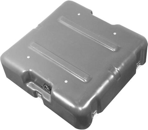
4 Motor won t start with gauge pressure at 0 psi The thermal protection of the compressor may have been activated. If system fans are still functioning, allow the unit to cool briefly and restart. If system fans are not running, a high amperage condition existed resulting in the system circuit breaker being tripped. This condition will result from a leaking check valve or malfunctioning unloader valve. Motor experiences labored start with gauge pressure below 0 psi This condition results from the motor attempting to restart with pressure in the cylinder. This is an indication of a leaking check valve or malfunctioning unloader valve. Inspect the check valve and the unloader switch. Service components as required. Motor starts at an intermediate pressure or Pressure relief valve is activated Disconnect the unit from the power source. Inspect the pressure switch for excessive wear and damaged or dirty components. Replace parts as required. Compressor cycles more frequently than is common Shut off compressor. Watch the tank pressure gauge. If the tank pressure drops rapidly, check tubing and fittings for leaks. If tubing and fittings are satisfactorily connected, the check valve should be inspected for dirt and damage. If after shut off tank pressure is maintained, the tank should be blown off. Water vapor can condense in the tank and reduce its capacity. Compressor takes longer to build tank pressure than is common Check system tubing and fittings for leaks. Inspect compressor air intake filters. Replace filter cartridge if required. No power to duplex outlet Verify system is powered. Reset duplex outlet circuit breaker. Disassembly, Repair, Replacement, Reassembly and Check Out The AA-CF has been designed for minimal required maintenance. Compressor service should be performed every two thousand hours and component service should be required only when component damage occurs or service life is exceeded. Modular construction makes component inspection and replacement simple. Maintenance can be performed with only the following tools: a / socket drive, a set of English Hex wrenches, a in. and an in. crescent wrench, flathead and # Phillips screwdrivers, and a / inch open face wrench. For Reassembly, Teflon tape or an equivalent thread sealant should be applied to all pneumatics fittings and a serviceable thread locking compound should be applied to all fasteners. To check the success of any repair, perform the procedure detailed in the Performance Verification section. The first step in any major component replacement is the removal of the compressor chassis from the case bottom. Compressor Chassis Removal Tools: / in. socket wrench and serviceable thread locking compound.. Remove case top.. Carefully place unit top cover down.. Remove the case bumper screws, sealing washers and case bumpers. Reference Figure B. Lift off case bottom. Use a rocking motion to clear ID plate rivets.. Replace by reversing steps. Secure case bumper screws using thread locking compound. Page
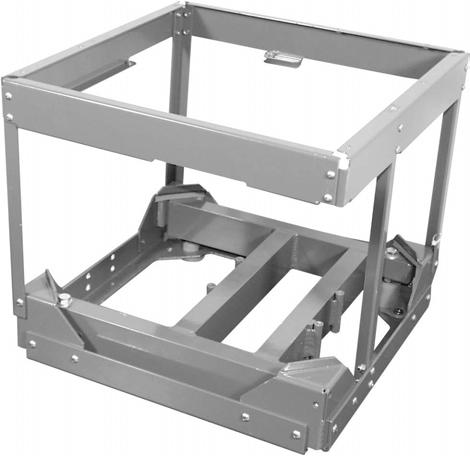
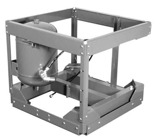
5 Figure A AA-CF Component Identification Intake Fan Assembly Exhaust Baffle Aftercooler Housing Assembly Pressure Switch Air Storage Tank Assembly Compressor Transformer Electronics Module Figure B Compressor Chassis Removal Case Bumper Screws Page


. 9. Remove the four motor mount bolts. 0.")

6 Compressor Removal Reference Figure Group C Tools: / and / hex drive or Allen wrench, flat head screwdriver, in. or smaller crescent wrench, pliers, and / open face wrench.. Remove compressor chassis from case bottom as per the Compressor Chassis Removal section.. Loosen the duct clamp at on the motor side of the intake hose and remove the hose from the motor intake.. Loosen the nut on the motor tee fitting and remove the / tubing.. Disconnect the ground wire from under the capacitor cover.. Loosen the exhaust duct and twist it free from of the compressor.. Disconnect the five insulated terminals from the back of the compressor.. Disconnect the two inline connectors.. Place the compressor chassis on its right side (motor intake down). 9. Remove the four motor mount bolts. 0. Lift the compressor chassis off of the free compressor.. Repair and reassemble by reversing steps. Replace motor connections in their original locations. See figure C or Figure I System Wiring Diagram. Note: There are two possible terminal locations at and. Either location is acceptable. Motor Tee Fitting Motor Intake Duct Clamp Location Figure Group C Compressor Removal Exhaust Duct Ground Wire Location Under Capacitor Cover Motor Mounting Bolts () Inline Connectors and Insulated Terminals Brown Violet Blue Black Orange White Page
7 Figure D Service Kit Installation 0 9 ITEM PART NUMBER Cylinder Head *Head Gasket *Outlet Valve Included With Motor Service Kit Service Kit Plate Valve 00 *Inlet Valve *Cylinder Gasket Service Kit Service Kit Cylinder 00 9 *Piston Ring *Piston Seal Service Kit Service Kit 0 Piston Rod Assembly 00 *Rider Ring Motor Mount Bolt, Nut, Washer Service Kit Commercial Motor 00 Motor Tee Fitting 0 Motor Intake Assembly 0-0 Crossover Tube 0-0 Motor Elbow Fitting 0 *Felt Service Kit 9 Service Kit 0 * Denotes parts included in the Service Kit. Page
8 Compressor Motor Service Kit Installation Reference Figure D (Adapted from Gast Operation & Maintenance Technical Manual). The compressor motor service kit contains the following: Head Gasket, Valves, Cylinder gasket, Piston Rings, Piston Seals, Rider Ring, and Felts. Dis-Assembly Tools: /, /, and / hex drive or Allen wrench, flat head screwdriver, in. or smaller crescent wrench, pliers, and / open face wrench.. Disconnect the compressor from the electrical power.! CAUTION! You must disconnect the pump from electrical power before servicing it. Failure to do so can result in severe personal injury or death.. Drain the air storage tank and turn the pressure switch to the OFF position.! CAUTION! You must vent all air lines to the compressor to remove pressure before servicing. Failure to do so can result in severe personal injury.. Remove the unit from the case bottom and the compressor from the compressor chassis as described in the Compressor Chassis removal and Compressor Removal subsections above.. Remove the motor intake and the crossover tube from the compressor.. Remove the cylinder heads, and valve components. DO NOT re-arrange or reorient the valve components.. Remove the cylinder and rings. Make sure all compressor parts are clean before reassembling. DO NOT use any chlorinated solvents to clean valves, or any liquids to flush units. The stainless steel valves may be cleaned with water. All parts, except the valves, can be cleaned with any industrial, non-flammable, non-toxic, non-petroleum based cleaning solvent. Assembly. Install piston seals, piston rings, and rider ring on each piston.. Locate ring joints approximately opposite each other.. Finger tighten the cylinders to the bracket with the cylinder screws and washers.. With the piston in its top dead center position, adjust each cylinder flush with top of piston and torque cylinder screws to 0-0 inch lbs. Re-torque second time.. Stack the valve components in order as originally assembled.. Install the cylinder head and head screws. NOTE: The exhaust ports in the cylinder heads have been marked by omitting the ends of two of the fins.. Torque all head screws 0-0 inch lbs.. Turn the motor shaft by hand at this point to ensure that the rod assembly is not hitting the head. NOTE: If rod assembly does hit head, loosen cylinders and re-adjust. 9. Replace the motor intake and crossover tube. 0. Re-torque head screws again after running for 0 minutes. Replacing Aftercooler Housing Parts Reference Figure E Aftercooler Fan Replacement Tools: / hex drive or Allen wrench, # Phillips screwdriver, in. or smaller crescent wrench, and thread locking compound.. With compressor chassis extracted remove the five aftercooler housing bolts from the top cover.. Lift aftercooler housing and disconnect the fan plug. Page
9 Figure E - Aftercooler Removal Aftercooler Housing Screws () Fan Plug Push-In Elbow Fitting Straight Push-In Fitting Aftercooler Bolts () Release Rings. Remove media guard and media from the fan guard assembly.. Remove the four aftercooler fan bolts.. Replace aftercooler fan and reassemble by reversing steps. Secure aftercooler housing bolts with thread locking compound. Aftercooler Assembly Replacement Reference Figure E Tools: / and / hex drive or Allen wrench, flathead screwdriver, in. or smaller crescent wrench, serviceable thread locking compound and Teflon tape.. Remove compressor chassis from case bottom as per the Compressor Chassis Removal section.. Loosen the nut of the motor tee fitting which secures the motor/aftercooler tube. Remove the tubing from the motor tee fitting leaving the nut and ferrule on the tube. Reference Figure Group C. Depress the release ring on the aftercooler push-in elbow then pull free the motor/aftercooler tube previously loosened in step.. Remove the tank/aftercooler tube from the push-in elbow fitting on the tank by depressing the release ring and pulling on the tube. Note the tube routing.. Rotate the compressor chassis onto its left side (motor exhaust side). Depress the release ring on the push-in straight fitting at aftercooler and pull tube straight out.. Remove the five aftercooler housing screws, disconnect fan plug and remove aftercooler housing.. Slide the aftercooler toward the compressor chassis front (power inlet) and remove.. Clamp aftercooler block in vise and remove push-in fittings, straight fitting first, then elbow. Remove aftercooler manifold block screw and aftercooler cover plate. Minimize handling of the aftercooler to avoid cracking it. 9. Replace aftercooler assembly and reassemble by reversing steps, being careful to reroute tubing as noted during removal. Seal threaded ends of aftercooler push-in fittings with Teflon tape or sealing compound and secure aftercooler housing bolts and aftercooler cover plate bolt with a serviceable thread locking compound. Page 9
10 Replacing Air Storage Tank Components Pressure Switch Replacement Reference Figure F Tools: / hex drive or Allen wrench, # Phillips screw driver, in. or smaller crescent wrench, thread sealing compound or Teflon tape.. Unplug the AA-CF compressor and drain the air storage tank.. Remove compressor chassis from case bottom as per the Compressor Chassis Removal section.. Remove four exhaust baffle screws to allow access to the pressure switch screws.. Loosen pressure switch cover screw and remove pressure switch cover.. Loosen the unloader valve nut and remove unloader tube.. Loosen screws on the pressure switch to release the motor power leads, the control wire leads and the switch ground. When replacing leads, be sure the wire pair leading through the motor exhaust chassis to the motor connects to the MOTOR location on the pressure switch and that the wire pair from the control wire set, contained in polyester braid, connects to the LINE location of the pressure switch. Similar wire colors should attach on the same side of the pressure switch.. Remove pressure relief valve, female quick connect fitting, and pressure gauge.. Using the hex of the coupler fitting, turn pressure switch off of the air storage tank. Guide wires slowly through the / grommet during the initial turn. 9. Remove the coupler fitting from the pressure switch. 0. Replace pressure switch and reassemble by reversing steps. Use Teflon tape to seal pipe threaded fittings. Note: In addition to exposing wire connections, removing the pressure switch cover exposes a pair of adjustment screws used to control the AA- CF compressor s cut off pressure and pressure range. By turning the metal screw clockwise the air storage tank cut off pressure is increased. Turning the plastic screw clockwise increases the separation between the cut off and cut in pressure. Air storage tank pressure should never be adjusted to exceed 0 psi. Check Valve Replacement Reference Figure G Tools: in. or smaller crescent wrench, Teflon tape or thread sealing compound.. Remove compressor chassis from case bottom as per the Compressor Chassis Removal section.. Loosen nuts on / poly fittings and disconnect unloader tube and tank side tank drain tube.. Push in the release ring of the push-in elbow fitting on the tank then pull tank/aftercooler tube loose.. Remove push-in elbow fitting and / tube fitting from the check valve.. Remove check valve from the air storage tank.. Replace check valve and reassemble by reversing steps. Use Teflon tape to seal pipe threaded fittings. Removing the Air Storage Tank Reference Figure G. Remove compressor chassis from case bottom as per the Compressor Chassis Removal section.. Complete Pressure Switch Replacement procedure omitting steps, 9 and 0.. Complete Check Valve Replacement procedure omitting steps and.. Remove three tank assembly screws and the / tube fitting on the tank bottom.. Rotate the air storage tank slowly clockwise and remove through the exhaust duct side of the compressor chassis leading with the tank bottom. Page 0
11 Figure F Pressure Switch Leads Peak Pressure Adjustment Compressor Cut-In/Cut-Off Pressure Differential Adjustment Unloader Valve Nut Motor Wire Connections Control Wire Connections Figure G Tank Removal Star Washer Tank Assembly Screws Check Valve / Tube Fittings Push-In Elbow Fitting Replacing Pneumatic Tubing. Loosen tube at both ends by depressing the push-in fitting release ring then the tube free or by removing the fitting nut.. Note the ferrule type on both ends of the tube then discard tube section and attached ferrules.. Select the correct tubing size and cut to the appropriate length: Motor / Aftercooler tube.0 in. Tank / Aftercooler tube. in. Unloader tube 0.0 in. Case side tank drain tube.0 in. Tank side tank drain tube.0 in. Case drain tube. in.. Slide the fitting nut and the appropriate new ferrule onto the tube and re-attach. When replacing tubing routed to the aftercooler, make aftercooler connections first. Page
12 Removing the Electronics Module Reference Figure I Tools: / hex drive or Allen wrench and serviceable thread locking compound.. Remove compressor chassis from case bottom.. Uncouple control wire set connector and motor wire set connector.. Remove the two electronics mounting screws.. Reattach by reversing steps. Install fasteners using a serviceable thread locking compound. Figure H Intake Fan Removal Intake Fan Screws Wire Nuts (one shown- second opposite 0 deg.) Figure I Electronics Module Motor Wire Set Connector Electrical Cover Transformer Bracket Screws & Star Washers Transformer Wire Set Connectors Control Wire Set Connector Elec. Mounting Screws Removing the Intake Fan Reference Figure H Tools: / hex drive or Allen wrench, flat head screwdriver, side cutters and serviceable thread locking compound.. Remove compressor chassis as per the Compressor Chassis Removal section.. Remove the 9 perimeter screws of the top cover.. Remove pneumatic tubing at tank elbow push-in fitting, motor tee fitting and tank drain poly fitting.. Lift off the top cover.. Remove the electrical cover on the fan motor to expose the electrical connections. Remove the two wire nuts and pull the two wire pairs through the / grommet.. Remove the two intake fan screws located on the underside of the top cover.. Remove the fan motor being careful not to bend the impeller. 9. Replace intake fan and reattach by reversing steps. Install fasteners using a serviceable thread locking compound. Strip wires / in. and reconnect using wire nuts. Connect one orange and one purple wire to each black fan lead. Individual wire orientation is not critical. Transformer Replacement Reference Figure I Tools: / hex drive or Allen wrench and thread locking compound.. Remove compressor chassis from case bottom.. Uncouple the connector between the transformer and the electronics box.. Remove the four transformer bracket screws.. Replace and reassemble by reversing steps. Apply thread locking compound to screws when installing. Be sure star washers are replaced under the bolt heads contacting the brackets and between the brackets and the chassis base. Note: To check the success of any repair perform the procedure detailed in the Verification section. Page
13 AA-CF SYSTEM WIRING SCHEMATIC Figure J AA-CF SYSTEM PNEUMATIC SCHEMATIC Figure K Page
14 PARTS LIST Reference Figure ITEM PART NUMBER QUANTITY Case, Mil. Spec., Bottom 0 Identification Plate, Case 09 Weather stripping 0 in. Case Bumper 009 SCREW, Hex head,stnl, Commercial /-0 x / Reference Figures & ITEM PART NUMBER QUANTITY 9 0 Case, Mil. Spec., Top 0 Case Leg 0-0 Case Leg Pivot 00-0 Case Leg Bumper 0 NUT, Nylok, Stnl, 0- Commercial 0V Power cord 000 0V Power cord 009 Cord Pouch 09-0 BOLT, Button head socket, Commercial Stnl,0- x / Washer, Sealing, Stnl, #0 0 Page


15 Figure Case Base Figure Case Top - Inside Figure Case Top - Outside 9 0 Page
16 Reference Figure ITEM PART NUMBER QUANTITY 9 0 Chassis Base 00 Vibration Isolator 0 SCREW, Flathead Phillips, Commercial Stnl, /-0 x / Chassis Corner Bracket 0 Motor Mount 0-0 NUT, Serrated flange, Stnl, /- Commercial WASHER, Mil. Spec. 9- Commercial BOLT, Hex head, Stnl, /- x Commercial Chassis Corner Angle 0-0 Chassis Side Angle 0-0 Chassis Cover Channel, Front 0-0 Chassis Cover Channel, Left 0-0 Chassis Cover Channel, Back 09-0 Chassis Cover Channel, Right 00-0 SCREW, Button head socket, Commercial Stnl, 0- x / SCREW, Button head socket, Commercial - x / WASHER, int. star, #0, stnl. Commercial WASHER, int. star, #, stnl. Commercial Reference Figure ITEM PART NUMBER QUANTITY Air Storage Tank 0-0 Check Valve 0 FITTING, Brass, Push-In Elbow, 09 / Tube x / MPT, Viton type FITTING, Brass, 0 / Poly x / MPT TUBING, Air Brake, / 00. in. SCREW, Button head socket, Commercial Stnl, 0- x / WASHER, int. star, #0, stnl. Commercial Page


17 Figure Compressor Chassis 9 0 Figure Air Storage Tank Page


18 Reference Figure ITEM PART NUMBER QUANTITY Transformer Assembly 0 Transformer Bracket 0-0 BOLT, Pan head Phillips, Commercial Stnl, 0- x NUT, Nylok, Stnl, 0- Commercial SCREW, Button head socket, Commercial Stnl, 0- x / WASHER, nylon, 0.0 thk 009 WASHER, int. star, #0, stnl. Commercial Reference Figure ITEM PART NUMBER QUANTITY 9 0 Compressor 00 Motor Intake 0-0 Crossover Tube 0-0 FITTING, A/B branch tee, 0 / tube x / MPT FITTING, A/B Male Elbow, 0 / tube x / MPT FITTING, Plug, 009 / MPT x / Hex countersink FITTING, deg., 000 / Flare x / MPT HOSE CLAMP, Marine grade, 0 / - /, Miniature width TUBING, / I.D. x 0.0 wall AA-A in. BOLT, Socket head, Stnl, Commercial /- x / WASHER, Mil. Spec. 9- Commercial NUT, Nyloc, Stnl, /- Commercial WASHER, int star, #, stnl 00 Page


19 Figure Transformer Figure Compressor 9 0 Page 9
20 Reference Figure ITEM PART NUMBER QUANTITY 9 0 Intake Fan 09 Intake Fan Gasket 09 SCREW, Button head socket, Commercial Stnl, 0- x / Intake Hose 09 in. HOSE CLAMP, Marine Grade, 000 / - / Intake Fan Filter Assembly 0 BOLT, Flat head Phillips, Commercial Stnl, - x / NUT, Nyloc, Stnl, - Commercial / Grommet 0 WIRE NUT, Blue Commercial WASHER, #0 Ext Star, Stnl 0 Reference Figure 9 ITEM PART NUMBER QUANTITY 9 0 Aftercooler Housing 09-0 SCREW, Button head socket, Commercial Stnl, 0- x / Aftercooler Fan 0 Aftercooler Fan Filter Assembly 0 BOLT, Flat head Phillips, Stnl, Commercial - x / NUT, Nyloc, Stnl, - Commercial Aftercooler Assembly 0 Aftercooler Cover Plate 09-0 SCREW, Socket head, Stnl, Commercial /-0 x / FITTING, Brass, Push-In Elbow, 09 / Tube x / MPT, Viton type FITTING, Brass, Push-In Straight, 0 / Tube x / MPT, Viton type TUBING, Air brake, / in. 0. in WASHER, int. star, #0, stnl. Commercial Page 0


21 Figure Intake Fan 9 0 Figure 9 Aftercooler 0 9 Page
22 Reference Figure 0 ITEM PART NUMBER QUANTITY Motor Exhaust Chassis 0 BOLT, Socket head, Commercial Stnl, /-0 x / NUT, Nyloc, Stnl, /-0 Commercial Motor Wire Set 0 Motor Exhaust Strain Relief 00 Strain Relief Nut 00 Wire Clamp, Steel, Plated 009 NUT, Nyloc, Stnl, - Commercial Reference Figure ITEM PART NUMBER QUANTITY Electronics Module 0 SCREWS, Button head socket, Commercial Stnl, 0- x / WASHER, # Star Stnl. 09 NUT, Nylok, Stnl. - Commercial WASHER, int. star, #0, stnl. Commercial Reference Figure ITEM PART NUMBER QUANTITY Pressure Switch, Port, Unloader 00 / Chrome Snapcap Hole Plug 00 / Grommet Pressure Gauge, / MPT 0 FITTING, Quick disconnect, AA- / Female x / MPT, w/ shut off FITTING, 009 / x / MPT Coupler, Stnl Safety Relief Valve 09 WASHER, #, Ext Star, Stnl 00 (Refer to Figure F, Page ) Page
23 Figure 0 Motor Exhaust Duct Figure Electronics Module Figure Pressure Switch Page

24 Reference Figures A & B ITEM PART NUMBER QUANTITY 9 0 Top Cover 0-0 Case Drain Fitting 0 Tubing Support Sleeve 009 TUBING, Air Brake, / in. 00 in. FITTING, Needle Valve, 0 / MPT x / Poly Angle FITTING, Bulkhead mount, 00 / FPT x 0- FITTING, 0- x / Poly 0 NUT, Wing, Brass, /-0 Commercial STUD, Brass, /-0 x / Commercial NUT, Jam, Brass, /-0 Commercial Duplex Outlet 00 Outlet Cover 009 SCREW, Pan head Phillips, Commercial Stnl, - x / A Circuit Breaker 00 A Circuit Breaker 00 Power Connection Chassis 09-0 SCREW, Flat head Phillips, Commercial Stnl, - x / SCREW, Button head socket, Commercial Stnl, 0- x / 9 Leg Socket SCREW, Flat head Phillips, Commercial Stnl, 0- x / 9 0 Intake Hose Trim 0 9. in. / Grommet 0 / Grommet 0 Inlet Wire Set 00 Control Wire Set 0 Wire Clamp, Steel, Plated 009 Wire Clamp, Nylon 00 Wire Clamp, Self Adhering 0 NUT, Nyloc, Stnl, - Commercial Handle 00 Exhaust Baffle 0-0 SCREW, Button head socket, Commercial 0 Stnl, 0- x / WASHER, int. star, #0, stnl. Commercial Page Weather Stripping 09 in.

25 Figure A Top Cover 9 0 Figure B Top Cover Page
26 Expendables ITEM PART NUMBER Felt, Filter Media 0 Compressor Rebuild Kit 0 Aftercooler Fan Filter Media 00 Intake Fan Filter Media 0 Page
27 Notes Page

28 For Further Service And/Or Technical Assistance Contact: Printed In The USA P.O. Box Woodinville, WA * -- * Fax: info@aseptico.com * Internet: /9 P/N 0
Hydraulics. Part B, Section 1. This section covers the following unit configurations. 3700V 3800V 3900V
 Part B, Section 1 Model Voltage Pump Manifold Control This section covers the following unit configurations. 3500V 3700V 3800V 3900V All Piston (F) 4-Port (A) 6-Port (B or C) -Port (S or T) Vista Standard
ELECTRICAL SYSTEM UPGRADE
 NEW CONTROLLER & ELECTRICAL SYSTEM UPGRADE FOR DAIRY TECH, INCORPORATED 10, 30 & 60G PASTEURIZERS Parts to Include 2 Wire ties (Nuts) 2 sticky wire mount pads Large Rubber Grommet (for bottom of electric
Installation Manual v1.0: Aurora Plus Turbo Kit ( ) 5.9L Dodge. Please read all instructions before installation.
 5.9L Dodge. Please read all instructions before installation.") Installation Manual v1.0: Aurora Plus - 4000 Turbo Kit (2003-2007) 5.9L Dodge Please read all instructions before installation. Figure 1: Aurora Plus - 4000 Kit Contents 1 Figure 2: Aurora Plus Hardware
Installation Manual v1.0: Aurora Plus - 4000 Turbo Kit (2003-2007) 5.9L Dodge Please read all instructions before installation. Figure 1: Aurora Plus - 4000 Kit Contents 1 Figure 2: Aurora Plus Hardware
PRODUCT SAFETY NOTICE DEALER/INSTALLER NOTICE
 PRODUCT SAFETY NOTICE Congratulations. This vehicle has been equipped with a Firestone air suspension system. This suspension will enhance the vehicle s handling when loaded, however, the vehicle s performance
HEAVY DUTY ONBOARD AIR SYSTEM PART NO
 IMPORTANT: It is essential that you and any other operator of this product read and understand the contents of this manual before installing and using this product. SAVE THIS MANUAL FOR FUTURE REFERENCE
MODEL NUMBER: MEDIUM DUTY ONBOARD AIR SYSTEM
 MODEL NUMBER: 10003 MEDIUM DUTY ONBOARD AIR SYSTEM IMPORTANT: It is essential that you and any other operator of this product read and understand the contents of this manual before installing and using
AIR/HYDRAULIC INJECTION GUN MODEL INSTRUCTIONS
 I. OPERATION & DESCRIPTION The Air / Hydraulic Injection Gun is a high-pressure tool that should be used with caution and according to these instructions. IMPORTANT: The Gun is 0,000 psi rated. Do not
Installation For Service Only
 For Service Only IMPORTANT! Aerada 1100 Series Low Arc Faucet S53-302 Battery Infrared Metering Faucet (Center Shank with 4" Trimplate) THIS SIDE UP! Packing List Read this entire installation manual to
6 Litre Oil-Less Air Compressor
 Operator s Manual 6 Litre Oil-Less Air Compressor WARNING! Before using this appliance, read the Operator s manual and follow all its safety rules and instructions. SPECIFICATION HWKAC1 1.1 kw / 1.5 HP
PRODUCT SAFETY NOTICE
 PRODUCT SAFETY NOTICE Congratulations. This vehicle has been equipped with a Firestone air suspension system. This suspension will enhance the vehicle s handling when loaded, however, the vehicle s performance
LEAK TEST PROCEDURE APPLICABLE TO DC3 INTELLI-GRIP LIFTERS MODELS MRT4-DC3, MRTA8-DC3, MRTALP8-DC3 AND PC/P1-DC3 SERIES
 LEAK TEST PROCEDURE APPLICABLE TO DC3 INTELLI-GRIP LIFTERS MODELS MRT4-DC3, MRTA8-DC3, MRTALP8-DC3 AND PC/P1-DC3 SERIES TESTING AND MAINTENANCE MUST BE DONE BY A QUALIFIED PERSON KEEP FOR FUTURE REFERENCE
348002K/348012K Manifold Block Style Service Manual 12/2000
 348002K/348012K Manifold Block Style Service Manual 12/2000 Service Manual 348002K/348012K Manifold Block Style Recovery/Recycling/Recharging Unit For R-12 or R-134a Only TABLE OF CONTENTS: Theory of Operation
Hydraulics. Part B, Section 1. This section covers the following unit configurations. 3400V 3500V 3700V
 Part B, Section 1 This section covers the following unit configurations. Model Voltage Pump Manifold Control 3100V 3400V 3500V 3700V All Piston (E) 4-Port (A) 6-Port (B or C) 2-Port (S or T) Vista Standard
Frame. Axle. Kit No Please read these instructions completely before proceeding with installation. Figure 1. Kit Parts List FORWARD B J
 Kit No. 70 Please read these instructions completely before proceeding with installation by www.airliftcompany.com MN-7 (008) ECN 08 Item P/N Description Qty. A B C D E F H I 807 0770 0006 88 70 87 8 8
INSTALL MANUAL. FOR ON LINE ORDERING- E Commerce Visit Our Website
 INSTALL MANUAL FOR ON LINE ORDERING- E Commerce Visit Our Website WWW.PRESSUREGUARD.COM Contact Information Technical Support: Chris@pressureguard.com Sales Support: Sales@pressureguard.com By Phone: 615-227-6024
Please read these instructions completely before proceeding with installation. Read all maintenance guidelines on page 7 before operating the vehicle.
 MN-643 (02511) ECR 5461 Kit No. 39205 Please read these instructions completely before proceeding with installation Item P/N Description Quantity A 26391 Driver-Side Beam Assembly 1 B 26414 Passenger-Side
TECHNICAL INSTRUCTIONS
 TECHNICAL INSTRUCTIONS 24 Month Maintenance Kit Instructions For Benchmark 2500-3000 Boilers Maintenance Kit # 58025-10 Flame Detector P/N 66034 Ignitor- Injector P/N 58023 Exhaust Manifold Seal P/N 84040
PN K K050012: Rebuild Kit for Delco Non-Delay Height Control Valve
 APPLICATION: 1959 1989 Cadillac, Oldsmobile, Buick, GMC Truck, Ford, Fruehauf Trailer INTRODUCTION This kit provides the necessary parts and instructions to rebuild Delco/King of the Road non-delay valves.
Instruction Sheet. 1/2 HP Portable Electric Pumps SAFETY FIRST. L2062 Rev. F 02/ IMPORTANT RECEIVING INSTRUCTIONS 2.
 Instruction Sheet 1/2 HP Portable Electric Pumps L2062 Rev. F 02/12 Index: English:...................................... 1-7 Français:.................................... 8-14 Deutsch:...................................
DISPLACEMENT PUMP INSTRUCTIONS-PARTS LIST Rev. K. Model , Series A Model , Series B Model , Series A
 INSTRUCTIONS-PARTS LIST INSTRUCTIONS This manual contains important warnings and information. READ AND KEEP FOR REFERENCE. DISPLACEMENT PUMP 308190 Rev. K 3000 psi (210 bar) MAXIMUM WORKING PRESSURE Model
69-74 VW Beetle IRS Rear Kit Part No
 www.airliftcompany.com 69-74 VW Beetle IRS Rear Kit Part No. 75615 MN-476 (01102) ECN 3455 Please read these instructions completely before proceeding with installation A C B E D AA F F ITEM QTY. PART
IBT Series Square Drive Torque Wrenches
 IBT Series Square Drive Torque Wrenches Operation and Maintenance Manual Model.75, 1, 3, 5, 8, 10, 20, 25, 35, 50 http://www.torsionx.com Use the IBT Series Square Drive Torque Wrenches Model.75, 1, 3,
HEAVY DUTY ONBOARD AIR SYSTEM
 HEAVY DUTY ONBOARD AIR SYSTEM PART NO. 10005 IMPORTANT: It is essential that you and any other operator of this product read and understand the contents of this manual before installing and using this
INSTALLATION INSTRUCTIONS
 28 INSTALLATION INSTRUCTIONS SECTION - AIR SPRING SECTION 2 - AIR ACCESSORY 2-5 ! IMPORTANT PLEASE DON T HURT YOURSELF, YOUR KIT OR YOUR VEHICLE. TAKE A MINUTE TO READ THIS IMPORTANT INFORMATION. This
Paint/Solvent/Dump Valve and Flow-Through Valve
 Instruction Sheet P/N 08573D Paint/Solvent/Dump Valve and Flow-Through Valve. Description See Figure. The paint/solvent/dump valve is a normally-closed valve that opens to trigger and/or dump coating material.
DISCONTINUED. Installation. Aerada 900 Series Futura Faucet. With Accu-Zone (AZ) Infrared Control
 Infrared Control") Aerada 900 Series Futura Faucet With Accu-Zone (AZ) Infrared Control BRADLEY SC A S53-141 4" Centerset S53-148 4" Centerset, no Solenoid Valve S53-186 4" Centerset with 8" Trim Plate S53-285 Centershank
Aerada 900 Series Futura Faucet With Accu-Zone (AZ) Infrared Control BRADLEY SC A S53-141 4" Centerset S53-148 4" Centerset, no Solenoid Valve S53-186 4" Centerset with 8" Trim Plate S53-285 Centershank
Surface CIMV, Low Flow, HTV, Manual
 Industries 5000 psi Operations and Maintenance Manual DOC-03715 Rev A Pioneering an Industry TABLE OF CONTENTS About SkoFlo... 2 General Information... 2 Hydraulic Ratings... 3 Storage... 3 Installation...
ALU-29CF Portable Light NSN:
 ALU-29CF Portable Light NSN: 6520-01-446-4170 COMMAND l AIR OPERATION / MAINTENANCE MANUAL & PARTS LIST TABLE OF CONTENTS Introduction................................................................3 Purpose.............................................................3
TECHNICAL INSTRUCTIONS
 TECHNICAL INSTRUCTIONS 24-Month Maintenance Kit Instructions for RECON 500 / 1000 Water Heaters Flame Detector Kit P/N 24356-2 Ignitor- Injector Kit P/N 58023 Exhaust Manifold Seal P/N GP-122537 Manifold
Purging Air From Divider Block Lubrication Systems
 FROST ENGINEERING SERVICE Purging Air From Lubrication Systems A D I V I S I O N O F G E C S E Y S A L E S & S E R V I C E DESCRIPTION Divider block lubrication systems operate correctly only when all
INSTALLATION INSTRUCTIONS FOR THE TRUCK MOUNTED VIPER ADDITIVE INJECTION SYSTEM GTP-8776C
 INSTALLATION INSTRUCTIONS FOR THE TRUCK MOUNTED VIPER ADDITIVE INJECTION SYSTEM GTP-8776C This additive injection system was designed to be used with five gallon jug of additive. The system is supplied
105 Commerce Way Westminster, SC Tel: (864) Fax: (864)
 Fax: (864)") ITT Conoflow 105 Commerce Way Westminster, SC 29693 Tel: (864) 647-9521 Fax: (864) 647-9574 WARNING Conoflow s products are designed and manufactured using materials and workmanship required to meet all
ITT Conoflow 105 Commerce Way Westminster, SC 29693 Tel: (864) 647-9521 Fax: (864) 647-9574 WARNING Conoflow s products are designed and manufactured using materials and workmanship required to meet all
Installation Instructions
 Installation Instructions for 15912 to 15916 Electric Fuel Pumps & Fuel Pressure Regulators Installation Instructions WARNING! These instructions must be read and fully understood before beginning the
Troubleshooting Guide: 355 Lights (12V)
") Troubleshooting Guide: 355 Lights (12V) Contents Description Refer To: Troubleshooting - Troubleshooting Chart Adjustments / Repair Procedures Bulb Replacing the Bulb Fuse(s) Replacing the Fuse (Ceiling)
Troubleshooting Guide: 355 Lights (12V) Contents Description Refer To: Troubleshooting - Troubleshooting Chart Adjustments / Repair Procedures Bulb Replacing the Bulb Fuse(s) Replacing the Fuse (Ceiling)
WARNING Carefully Read These Instructions Before Use
 DO NOT RETURN THIS SPRAYER TO STORE Call: 1-800-950-4458 Backpack Sprayer Use and Care Manual Manufactured for Northern Tool + Equipment Co., Inc. WARNING Carefully Read These Instructions Before Use Model
HALLMARK INDUSTRIES INC
 Performance Part No. HP. CONVERTIBLE JET PUMP USER S MANUAL GPH of Water @ Total Discharge Pressure of 40 psi Max. Pressure Max suction (shallow well) Max Suction (deep well) Max GPM (@0 head) Max Discharge
SPE-DEX 3100 Solid Phase Extraction System
 SPE-DEX 3100 Solid Phase Extraction System Service Manual 16 Northwestern Drive, Salem, NH 03079 Telephone: (603) 893-3663 Toll-Free: (800) 997-2997 USA Only Website: www.horizontechinc.com Copyright 2016
LAWN SPRINKLER, IRRIGATION PUMP
 LAWN SPRINKLER, IRRIGATION PUMP MODEL #, SP0P, SP5P, SP20P, EL0P, EL5P, EL20P SAFETY INFORMATION Please read and understand this entire manual before attempting to assemble, operate or install the product.
 Operation and Maintenance Manual Model.75,, 3, 5, 8, 0, 0, 5, 35, 50 http://www.torsionx.com Use the MaxDrv Series Square Drive Torque Wrench Model.75,, 3, 5, 8, 0, 0, 5, 35, 50 to install and remove threaded
Pressure Relief Valve Maintenance Manual
 Technical Manual 1098T Pressure Relief Valve Maintenance Manual Farris Engineering Division of Curtiss-Wright Flow Control Corporation TABLE OF CONTENTS - Manual Revision 0 Introduction & Safety Tips...
ADVANTAGE Annual Preventive Maintenance Instructions
 ADVANTAGE Annual Preventive These instructions should be followed to perform preventive maintenance on the Advantage reprocessor. Before commencing work on the reprocessor, ensure that you have the appropriate
Not required for most applications. Not required for most applications. High pressure ( provided) High pressure ( provided)
 High pressure ( provided)") ELECTRIC FUEL PUMPS P/N 12-801-1, 712-801-1, 12-802-1, 12-802-2, 712-802-1, 12-812, 12-815-1, & 712-815-1 FUEL PRESSURE REGULATORS P/N 12-500, 12-501, 12-803, 12-803BP, 12-804, & 15812NOS Installation
ELECTRIC FUEL PUMPS P/N 12-801-1, 712-801-1, 12-802-1, 12-802-2, 712-802-1, 12-812, 12-815-1, & 712-815-1 FUEL PRESSURE REGULATORS P/N 12-500, 12-501, 12-803, 12-803BP, 12-804, & 15812NOS Installation
KIT No , and 80590
 KIT No. 80531, 80545 and 80590 by MN-354 (05603) ECR 5593 Please read these instructions completely before proceeding with installation Air Spring Kit Parts List Item Description Quantity A Air Spring
Do not have any open flame or heat sources close to the installation
 March 6, 2017 IS# 791 Page 1 of 16 Thank you for purchasing a Transfer Flow, Inc. 50-gallon replacement fuel system for your 2011-16 Ford diesel short bed pickup. This system will fit any 2x4 or 4x4 crew
A-4000 Series Oil Removal and Pressure Reducing Stations & Air Compressor Accessories
 Pneumatic Air Supply Manual 718 Filter Stations Section Product Bulletin Issue Date 0907 A-4000 Series Oil Removal and Pressure Reducing Stations & Air Compressor Accessories Oil Removal and Pressure Reducing
MEDIUM DUTY ONBOARD AIR SYSTEM
 MEDIUM DUTY ONBOARD AIR SYSTEM PART NO. 10003 IMPORTANT: It is essential that you and any other operator of this product read and understand the contents of this manual before installing and using this
VALVE AND PLUMBING KIT INSTRUCTIONS SMC 84Q & 2408 LOADERS NEW HOLLAND TRACTORS MODEL 2WD 4WD LESS CAB WITH CAB 1720 X X X 1920 X X X
 ASSEMBLY MANUAL Keep With Operator s Manual VALVE AND PLUMBING KIT INSTRUCTIONS SMC 84Q & 2408 LOADERS NEW HOLLAND TRACTORS MODEL 2WD 4WD LESS CAB WITH CAB 1720 X X X 1920 X X X TRACTOR AND VALVE KIT GENERAL
Installation Instructions COMPETITION/PLUS SHIFTER Ford Mustang MT82 6-Speed Manual Transmission Catalog#
 Installation Instructions COMPETITION/PLUS SHIFTER 2015-2017 Ford Mustang MT82 6-Speed Manual Transmission Catalog# 3916037 Rev. 00 WORK SAFELY! For maximum safety, perform this installation on a clean,
Sachs shock manual. ( ) 2 & 4 Stroke RR Enduro. ( ) RS Dual Sport
 2 & 4 Stroke RR Enduro. ( ) RS Dual Sport") Sachs shock manual (2013 2015) 2 & 4 Stroke RR Enduro (2014-2015) RS Dual Sport 1 Introduction The procedures in this manual must take place in a clean environment using professional tools and some specific,
Sachs shock manual (2013 2015) 2 & 4 Stroke RR Enduro (2014-2015) RS Dual Sport 1 Introduction The procedures in this manual must take place in a clean environment using professional tools and some specific,
INSTALLATION, OPERATION AND MAINTENANCE MANUAL (IOM)
") INSTALLATION, OPERATION AND MAINTENANCE MANUAL (IOM) IOM-1088 03-16 Model 1088 Vacu-Gard Blanketing Valve ISO Registered Company SECTION I I. DESCRIPTION AND SCOPE The Model 1088 Vacu-Gard is a tank blanketing
INSTALLATION, OPERATION AND MAINTENANCE MANUAL (IOM) IOM-1088 03-16 Model 1088 Vacu-Gard Blanketing Valve ISO Registered Company SECTION I I. DESCRIPTION AND SCOPE The Model 1088 Vacu-Gard is a tank blanketing
6L Oil-less Air Compressor 53103
 6L Oil-less Air Compressor 53103 Operating Instructions Please read and save these instructions before attempting to assemble, install, operate or maintain the product. Protect yourself and others by observing
Installation Instructions
 Instructions Aerada 900 Series Futura Faucet With Battery (BIR) Infrared Control S53-284 4" Centerset/Centershank S53-289 Centerset/Centershank w/plate Table of Contents Pre- Information............2 900
Installation Manual v1.0: MST Turbo Kit ( ) 5.9L Dodge. Please read all instructions before installation.
 5.9L Dodge. Please read all instructions before installation.") Installation Manual v1.0: MST Turbo Kit (2003-2007) 5.9L Dodge Please read all instructions before installation. Figure 1: MST Kit Contents Figure 2: MST Hardware Kit Please make sure all of the components
Installation Manual v1.0: MST Turbo Kit (2003-2007) 5.9L Dodge Please read all instructions before installation. Figure 1: MST Kit Contents Figure 2: MST Hardware Kit Please make sure all of the components
Troubleshooting Guide: 355 Lights (24V)
") Troubleshooting Guide: 355 Lights (24V) Contents Description Refer To: Troubleshooting - Troubleshooting Chart Adjustments / Repair Procedures Bulb Replacing the Bulb Fuse(s) Replacing the Fuse (Ceiling)
Troubleshooting Guide: 355 Lights (24V) Contents Description Refer To: Troubleshooting - Troubleshooting Chart Adjustments / Repair Procedures Bulb Replacing the Bulb Fuse(s) Replacing the Fuse (Ceiling)
Section 10 Chapter 17
 Section 10 Chapter 17 24 Valve, 8.3 Liter Engine Air Intake System Note: All coding used in the 8.3 Liter and 9 Liter engine manuals are Cummins engine codes. These engine codes have no meaning to New
INSTALLATION INSTRUCTIONS
 2807 INSTALLATION INSTRUCTIONS SECTION - AIR SPRING SECTION 2 - AIR ACCESSORY -6 ! IMPORTANT PLEASE DON T HURT YOURSELF, YOUR KIT OR YOUR VEHICLE. TAKE A MINUTE TO READ THIS IMPORTANT INFORMATION. This
SD Bendix E-10PR Retarder Control Brake Valve DESCRIPTION. OPERATION - Refer to Figure 2
 SD-03-832 Bendix E-10PR Retarder Control Brake Valve MOUNTING PLATE SUPPLY 4 PORTS ELECTRICAL AUXILIARY DESCRIPTION TREADLE RETARDER CONTROL SECTION EXHAUST DELIVERY 4 PORTS FIGURE 1 - E-10PR RETARDER
OIL COOLER KIT CHEVY CAMARO 2.0T PARTS LIST AND INSTALLATION GUIDE INSTALL DIFFICULTY DISCLAIMER CAUTION TOOLS NEEDED NOTE INSTALL PROCEDURE
 PARTS LIST AND PARTS INCLUDED 3PC APPLICATION-SPECIFIC MOUNTING BRACKETS 1PC HORN RELOCATION MOUNTING BRACKET 1PC 25-ROW OIL COOLER (SLEEK SILVER OR STEALTH BLACK) 1PC 4'4" STAINLESS STEEL BRAIDED HOSE
 Operation and Maintenance Manual http://www.torsionx.eu Use the MaxDrv Series Square Drive Torque Wrench Model.75, 1, 3, 5, 8, 10, 20, 25, 35, 50 to install and remove threaded fasteners requiring precise
Tech. Services: (800) Fax: (800) Order Entry: (800) Fax: (800)
 Fax: (800) Order Entry: (800) Fax: (800)") SPX Corporation 5885 11th Street Rockford, IL 61109-3699 USA Internet Address: http://www.hytec.com Tech. Services: (800) 477-8326 Fax: (800) 765-8326 Order Entry: (800) 541-1418 Fax: (800) 288-7031 Parts
SPX Corporation 5885 11th Street Rockford, IL 61109-3699 USA Internet Address: http://www.hytec.com Tech. Services: (800) 477-8326 Fax: (800) 765-8326 Order Entry: (800) 541-1418 Fax: (800) 288-7031 Parts
UNIVERSAL PUMP HANGER INSTALLATION INSTRUCTIONS
 UNIVERSAL PUMP HANGER INSTALLATION INSTRUCTIONS WARNING! THESE INSTRUCTIONS MUST BE READ AND FULLY UNDERSTOOD BEFORE BEGINNING INSTALLATION. FAILURE TO FOLLOW THESE INSTRUCTIONS MAY RESULT IN POOR PERFORMANCE,
INSTALLATION AND MAINTENANCE OF TOP LOADING ARM
 INSTALLATION AND MAINTENANCE OF TOP LOADING ARM D TABLE OF CONTENTS 1. INTRODUCTION 04 2. SPECIFICATION OF THE REDLANDS LOADING ARM 04 3. INSTALLING THE LOADING ARM 3.1. Installation Procedures 05 4.
HexPro Series Low Profile Wrenches
 HexPro Series Low Profile Wrenches Operation and Maintenance Manual Model 2HP 4HP 8HP 14HP 30HP www.torquetoolsinc.com Use the HEXPRO Series Low Profile Wrenches Model 2HP 4HP 8HP 14HP 30HP to install
Fisher 657 Diaphragm Actuator Sizes and 87
 Instruction Manual 657 Actuator (30-70 and 87) Fisher 657 Diaphragm Actuator Sizes 30 70 and 87 Contents Introduction... 1 Scope of Manual... 1 Description... 2 Specifications... 2 Installation... 3 Mounting
LABORATORY ZERO AIR GENERATOR MODEL N-GC1500 USER S MANUAL
 LABORATORY ZERO AIR GENERATOR MODEL N-GC1500 USER S MANUAL Content 1. Introduction...2 2. Important safety instruction...3 3. System component...4 4. Engineering design overview...5 5. Installation...6
OPERATING SERVICE MAINTENANCE MANUAL
 OPERATING SERVICE MAINTENANCE MANUAL ALL-STAR ROCKING PISTON COMPRESSOR AND VACUUM PUMP Registered by one or more of these standards agency ISO RoHS 9001 Compliant CE Read through carefully and understand
P-600. Technical Manual. Troubleshooting Repairs Replacements
 P-600 Technical Manual Troubleshooting Repairs Replacements Table of Contents P-600 Lift Symptoms and Problems Finding the Problem Before Getting Inside 3 Pneumatic Systems 4 Electrical Systems 5 Mechanical
RUFNEX Series Low Profile Wrenches Operation and Maintenance Manual
 RUFNEX Series Low Profile Wrenches Operation and Maintenance Manual http://www.torsionx.com Use the RUFNEX Series Ultra-Low Profile Wrenches to install and remove large bolts that have minimal wrench clearance.
Meritor WABCO Antilock Braking System (ABS) 42.06
 42.06") Meritor WABCO Antilock Braking System (ABS) 4.06 Control Valve Replacement Replacement NOTE: Wire repairs may require the use of special tools for certain connectors and terminals. See Group 54 for information
Meritor WABCO Antilock Braking System (ABS) 4.06 Control Valve Replacement Replacement NOTE: Wire repairs may require the use of special tools for certain connectors and terminals. See Group 54 for information
Installation Instructions
 Instructions Aerada 90-75 Series Metering Faucet S53-053 90-75 Series Metering Faucet with 4" Centerset S53-082 90-75 Series Metering Faucet with 4" Centerset & 8" Trim Plate S53-058 90-75 Series Metering
WALKIE HIGH LIFT HYDRAULIC SYSTEM
 WALKIE HIGH LIFT HYDRAULIC SYSTEM W30-40ZA [B453]; W20-30ZR [B455]; W25-30-40ZC [B454] PART NO. 1524251 2000 SRM 1025 SAFETY PRECAUTIONS MAINTENANCE AND REPAIR When lifting parts or assemblies, make sure
BMK-12. Dual-Gard By-Pass Filter Mounting Kit Installation and Servicing Instructions
 BMK-12 Dual-Gard By-Pass Filter Mounting Kit Installation and Servicing Instructions IMPORTANT NOTICE Read all instructions completely before attempting to install this unit. Improper installation could
6200 Series. Specifications. Fluid End Power End Models 6211, 6212, 6221, & 6222 Models 6241 & 6242 Part Material Part Material Part Material
 5.2018.12.i 6200 Series Specifications The Flomore 6200 Series Pump line consists of a series of basic pump options all developed from a modular power unit. All units are pneumatically driven positive
LEAK TEST PROCEDURE MRT4-DC LIFTERS SINGLE VACUUM SYSTEMS TESTING AND MAINTENANCE MUST BE DONE BY A QUALIFIED PERSON KEEP FOR FUTURE REFERENCE
 LEAK TEST PROCEDURE MRT4-DC LIFTERS SINGLE VACUUM SYSTEMS TESTING AND MAINTENANCE MUST BE DONE BY A QUALIFIED PERSON KEEP FOR FUTURE REFERENCE TST-011 Rev. 2013-049 Page 1 of 12 THIS PAGE INTENTIONALLY
SERIES OPERATION AND MAINTENANCE MANUAL
 SERIES OPERATION AND MAINTENANCE MANUAL This manual CONTAINS IMPORTANT WARNINGS, S and OTHER INSTRUCTIONS. Read and understand the instruction manual Carefully, before use and retain it for reference.
INSTRUCTION AND MAINTENANCE MANUAL GFH45 PRESSURE REGULATOR
 Enidine / Conoflow 105 Commerce Way Westminster, SC 29693 Tel: (864) 647-9521 Fax: (864) 647-7993 WARNING Conoflow s products are designed and manufactured using materials and workmanship required to meet
TECHNICAL INSTRUCTIONS
 TECHNICAL INSTRUCTIONS 24-Month Maintenance Kit Instructions for ReCon 500 / 1000 Water Heaters Flame Detector Kit P/N 24356-2 (1 each) Ignitor- Injector Kit P/N 58023 (1 each) Exhaust Manifold Seal P/N
Steamin Demon Classic High-Flow Carpet Cleaning System
 Steamin Demon Classic High-Flow Carpet Cleaning System Repair Manual & Parts List For technical assistance or to order parts, call toll-free 1-888-413-6748 Fax: 740-587-1394, Email: info@steamindemon.com
KAM IAS ISOKINETIC AUTOMATIC SAMPLER. User Manual IASMANUAL-0513 KAM CONTROLS, INC Ann Arbor Drive Houston, Texas USA
 An ISO 900 certified company TEL + 73 784-0000 FAX + 73 784-000 Email Sales@Kam.com KAM IAS ISOKINETIC AUTOMATIC SAMPLER PER API 8.2, ASTM D477 AND ISO 37 User Manual IASMANUAL-053 3939 Ann Arbor Drive
HVF110, 210, 310, 410HD
 342 N. Co. Rd. 400 East Valparaiso, IN 46383 219-464-8818 Fax 219-462-7985 www.heatwagon.com Installation and Maintenance Manual Please retain this manual for future reference. HVF110, 210, 310, 410HD
GPS AutoSteer System Installation Manual
 GPS AutoSteer System Installation Manual Supported Vehicles MacDon M150 M200 PN: 602-0232-01-A LEGAL DISCLAIMER Note: Read and follow ALL instructions in this manual carefully before installing or operating
Low Profile Wrenches Operation and Maintenance Manual
 Low Profile Wrenches Operation and Maintenance Manual http://www.torquetoolsinc.com Use the HEXPRO Series Low Profile Wrenches Model 2HP 4HP 8HP 14HP 30HP to install and remove large bolts that have minimal
PART NUMBER: MINI Cooper S L4-1.6L SEE * NOTE
 Equipped with AEM Dryflow Filter No Oil Required! INSTALLATION INSTRUCTIONS PART NUMBER: 21-699 2007-2010 MINI Cooper S L4-1.6L SEE * NOTE * NOTE: Legal in California only for racing vehicles which may
EURO BEAD BREAKER MODEL # Instruction Manual Parts Breakdown
 EURO BEAD BREAKER MODEL #10107 Instruction Manual Parts Breakdown Operation WARNING The optional air/hydraulic pump is capable of generating fluid pressure up to 10,000 PSI. Keep both hands on the handles
GPS AutoSteer System Installation Manual
 GPS AutoSteer System Installation Manual Supported Vehicles Case IH Combines 7010 7120 8010 8120 AFX 8010 9120 PN: 602-0283-01-A LEGAL DISCLAIMER Note: Read and follow ALL instructions in this manual carefully
ELECTRIC FUEL PUMPS P/N , , & FUEL PRESSURE REGULATOR P/N
 ELECTRIC FUEL PUMPS P/N 80000100, 80000101, & 80000102 FUEL PRESSURE REGULATOR P/N 80000103 Installation Instructions 199R10583 These instructions must be read and fully understood before beginning the
82-01 Chevy S-10/ GMC Sonoma Front Kit Part No B
 www.airliftcompany.com 82-01 Chevy S-10/ GMC Sonoma Front Kit Part No. 75512B MN-481 (02105) ECN 3549 Please read these instructions completely before proceeding with installation Left Side Upper Shock
The full WeatherTRAK Flow3 Installation and Maintenance Manual is available online at
 Installation Manual INTRODUCTION The full WeatherTRAK Flow Installation and Maintenance Manual is available online at www.weathertrak.com General Description A WeatherTRAK Flow combines a hydraulic master
ELECTRIC SPRAYER CONTROL SYSTEM OWNERS MANUAL
 -- AB00 Rev. 0 ELECTRIC SPRAYER CONTROL SYSTEM OWNERS MANUAL REPLACEMENT PARTS READ complete manual CAREFULLY BEFORE attempting operation. DEMCO Dethmers Mfg. Co. P.O. Box 0 0th Street Boyden, IA PH: ()
SECTION 4 - FUEL/LUBRICATION/COOLING
 For Arctic Cat Discount Parts Call 606-678-9623 or 606-561-4983 SECTION 4 - FUEL/LUBRICATION/COOLING 4 TABLE OF CONTENTS Carburetor Specifications... 4-2 Carburetor Schematic... 4-2 Carburetor... 4-3 Cleaning
LEAK TEST PROCEDURE DC CHANNEL LIFTERS SINGLE VACUUM SYSTEMS TESTING AND MAINTENANCE MUST BE DONE BY A QUALIFIED PERSON KEEP FOR FUTURE REFERENCE
 LEAK TEST PROCEDURE DC CHANNEL LIFTERS SINGLE VACUUM SYSTEMS TESTING AND MAINTENANCE MUST BE DONE BY A QUALIFIED PERSON KEEP FOR FUTURE REFERENCE TST-008 Rev. 2013-048 Page 1 of 10 THIS PAGE INTENTIONALLY
PILLOWS DECK-MOUNT BATH FAUCET WITH FLUME SPOUT
 PILLOWS DECK-MOUNT BATH FAUCET WITH FLUME SPOUT BEFORE YOU BEGIN NOTES Observe all local plumbing and building codes. Advance planning before installation is crucial. Carefully read the entire instructions
TABLE OF CONTENTS. Ram Assembly
 TABLE OF CONTENTS DUC Cover------------------------------------------------------------------------------------ 00 Table of Contents----------------------------------------------------------------------------
IE B9 A4/A5 Cold Air Intake Install Guide
 IE B9 A4/A5 Cold Air Intake Install Guide Thank you for purchasing another high quality Integrated Engineering product! This instruction guide is used for installation of IE s Cold Air Intake Kit for Audi
Transmission Overhaul Procedures-Bench Service
 How to Assemble the Lower Reverse Idler Gear Assembly Special Instructions In 1996 Eaton changed the reverse idler system design. In the nut design, the reverse idler bearing was lubricated through a hole
SPECIFICATIONS: Tank Size: 80 gallons PUMP RPMs: 1050 CFM: 40PSI; 90 PSI Max Pressure: 150 PSI Thermal overload protection
 5HP 80 GALLON TWO STAGE COMPRESSOR Models: 51866, 51870 CALIFORNIA PROPOSITION 65 WARNING: You can create dust when you cut, sand, drill or grind materials such as wood, paint, metal, concrete, cement,
Equipped with AEM Dryflow Filter No Oil Required! INSTALLATION INSTRUCTIONS PART NUMBER: C
 Equipped with AEM Dryflow Filter No Oil Required! INSTALLATION INSTRUCTIONS PART NUMBER: 21-721C 2011-2013 MINI Cooper S L4-1.6L SEE NOTE* 2011-2013 MINI Clubman S L4-1.6L SEE NOTE* 2011-2013 MINI Cooper
Kit No Please read these instructions completely before proceeding with installation. Parts List G J I K L H CC FF DD MN-505 (01201) NPR 3733
 NPR 3733") Kit No. 57154 MN-505 (01201) NPR 3733 Please read these instructions completely before proceeding with installation Parts List by www.airliftcompany.com Item P/N Description Quantity A 58407 Air Spring
Kit No. 57154 MN-505 (01201) NPR 3733 Please read these instructions completely before proceeding with installation Parts List by www.airliftcompany.com Item P/N Description Quantity A 58407 Air Spring
VALVE AND PLUMBING KIT NEW HOLLAND 7310 LOADER NEW HOLLAND TRACTORS
 ASSEMBLY MANUAL Keep With Operator s Manual VALVE AND PLUMBING KIT NEW HOLLAND 73 LOADER NEW HOLLAND TRACTORS MODEL 2WD FWA LESS CAB WITH CAB TT55 X X X TT75 X X X Valve and plumbing kit can be installed
Solstice Electric Fryers SE Series Service Manual
 Solstice Electric Fryers SE Series Service Manual L22-330 R1 (10/12) Notice In the event of problems or questions about your order, contact the Pitco Frialator factory at (603) 225-6684. In the event of