NLDC-25 Dual Battery Isolator and Charger
|
|
|
- Regina Suzanna Clarke
- 5 years ago
- Views:
Transcription

1
2 Index Introduction Safety Information External features Preparing for Installation Fitting the NLDC-25 Universal Mounting Fixture Typical Installation diagram Installation steps Selecting battery type Ignition over-ride Temperature compensation Remote monitor Remote monitor operation Remote monitor warning messages Application examples Specifications
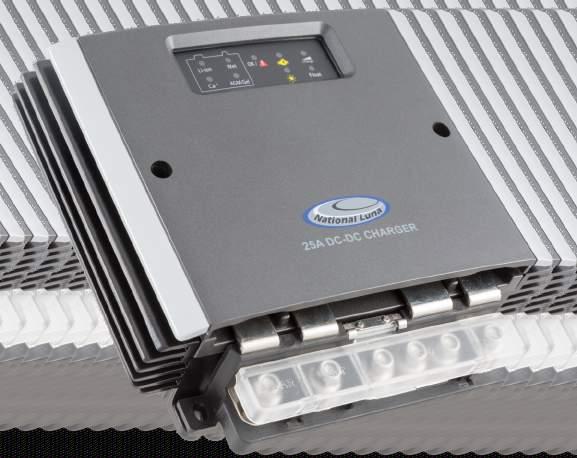
3 NLDC-25 Dual Battery Isolator and Charger The NLDC-25 from National Luna is a DC to DC battery charger and isolator for a dual-battery system. It will charge an auxiliary or service battery from a vehicle alternator or Solar panel up to 25A output current. Traditional 12V and 24V vehicle alternators as well as variable voltage alternators are supported. The integrated MPPT solar regulator provides a maximum output power of 375W but can support solar panels higher than this. Solar panel voltages up to 42V can be connected. The NLDC-25 features a 6-stage charge algorithm that is suitable for any Lead-Acid battery type as well as automotive Lithium-Ion batteries. 3 safety stages analyse the battery and can detect batteries that are damaged and unable to accept charge. Temperature compensation is used to optimise the output voltage, ensuring safe and full battery charging under various conditions. The NLDC-25 supports the connection of a remote monitor that displays information about the system and battery levels to the user on a high-contrast LCD screen. The NLDC-25 has a IP67 rating for harsh environments and is protected against reverse-polarity, over-voltage, over-temperature and over-current conditions. SAFETY INFORMATION : Before installation, read the instructions carefully. Before installation, disconnect any existing batteries. The NLDC-25 is used for charging 12V lead-acid and automotive Lithium batteries only. Do not use for any purpose other than battery charging. Do not attempt to power any devices or instruments directly using the output of NLDC-25. Do not attempt to charge a non-rechargeable or battery other than 12V. Never attempt to charge a damaged battery or leaking battery. Avoid open flames in the vicinity of the battery. Battery acid is highly corrosive. If your skin or eyes come into contact with acid, immediately rinse the affected area with water and seek medical advice. Do not alter or disassemble the NLDC-25 under any circumstances. Unauthorized disassembly, repairs or modifications will void any warranty. Attempts to use the NLDC-25 for purposes other than indicated in this manual will void the warranty. Ensure all connections are secure and cables are installed in a safe manner. Use the correct cabling size and fuses in accordance with the installation instructions. 1
4 NLDC-25 Features 4 NLDC-25 External features NL-DC25 Metal Base 2 - Remote monitor connecting port 3 - Status display 4 - Removable top cover 5 - Temperature compensation input 6 - Ignition over-ride input 7 - Removable terminal block 8 - Terminal block - Auxiliary battery output 9 - Terminal block - Common ground connections 10 - Terminal block - Alternator input 11 - Terminal block - SOLAR panel input 12 - Mounting feet Status Display 1 - Battery type selection button 1 Li-ion Ca+ Wet OK / AGM/Gel Battery Charge Float 2 - Battery type indicator 3 - OK / Fault indicator : Green = OK, Red = Fault 4 - Input source indicator (ALT or SOLAR) 5 - Charge stage indicator DC-DC Battery Charger 2
5 Preparing for Installation The NLDC-25 should be located close to the auxiliary battery for best voltage regulation. The NLDC-25 can operate in harsh environments but it is best installed in a location that is cooler with adequate ventilation. Avoid areas exposed to harsh or corrosive chemicals, excessive dust, extreme heat or mechanical movement. The NLDC-25 can be installed vertically or horizontally. Do not block or obstruct the cooling fins on the NLDC-25. Allow clearance around the NLDC-25 for cables and ventilation. It is normal for the NLDC-25 to get hot during operation, keep any objects that are heat-sensitive away from the NLDC-25. If the temperature compensation probe is used, it must be able to reach the auxiliary battery. 2 It is recommended to use 16mm cables for connections to the main and auxiliary batteries. Smaller gauge cables can be used for short distances. In-line fuses must be fitted in the positive cables close to the respective main and auxiliary batteries. Use the common ground connections on the terminal block for all negative cable connections. Use appropriate cable lugs for the cable size used. Removing the top cover In order to select the battery type and to install the temperature compensation & ignition over-ride wires, the top cover will need to be removed. Loosen the two screws as indicated in order to release the cover. 3
6 Fitting the NLDC-25 The NLDC-25 has 4 mounting feet, use these to attach the NLDC-25 to a secure, flat surface. Use appropriate screws or bolts to attach the NLDC-25 securely, M4 machine bolts are recommended. DO NOT drill into or modify the NLDC-25 housing. Allow enough clearance for power cables to connect to the terminal block. 50mm or more is recommended. It is recommended to secure cables together and prevent excessive movement in the final application. If the remote monitor is fitted, allow clearance for the plug and cable. Cable Clearance Universal mounting fixture The NLDC-25 is supplied with a universal mounting fixture and fasteners that can be used to aid installation in a variety of applications. This fixture allows the NLDC-25 to be attached in several ways depending on the application requirements. Use the supplied screws and washers to secure the NLDC-25 to the plate in the chosen orientation. Secure the fixture in the final application with appropriate fasteners. Flat washer Spring washer M4x20 screws 4
7 Step plates M4x20 screws Spring washer Flat washer The supplied step-plates can be used to raise the NLDC-25 above obstructions such as pipes or cables if necessary. Use the supplied screws and washers to assemble the fixture as shown in the diagram. Use appropriate fasteners to secure the assembled plate to the application. The NLDC-25 can be rotated on the plate by 90 to suite the application. Vertical or horizontal installation is supported. 5
8 Typical Installation SOLAR PANELS + FUSE FUSE MAIN AUX - 6
9 Installation Steps Disconnect the main battery before starting installation. Install the NLDC-25 using the mounting feet. (Described on page 4). Install positive and negative cables from the Auxiliary battery to the NLDC-25. Connect to the AUX and GND terminals respectively. Install one in-line fuse on the positive cable near to the Auxiliary battery. Do not connect the battery yet. Install positive and negative cables from the NLDC-25 to the Main battery. Connect to the ALT and GND terminals respectively. Install one in-line fuse on the positive cable near to the Main battery. If a solar panel is used, connect the positive and negative cables from the solar panel to the SOLAR and GND terminals respectively. Connect the temperature compensation probe and IGN over-ride cable if used. (See page 8). Install the remote monitor (if used) and run its cable to the remote monitor port on the NLDC-25. (See page 9). Double check all cables and connections for correct installation. Re-connect the Main battery. The NLDC-25 should now be powered and will show status on the status display. Select the Auxiliary battery type. See Selecting Battery Type below. Connect the Auxiliary battery. If the remote monitor is installed, the voltages of the Main and Auxiliary batteries will now be displayed. The system is now ready. Selecting Battery Type The NLDC-25 will optimise charge voltage based on the selected battery type. For safety reasons, the battery type cannot be changed if the AUX battery is already connected. Remove the NLDC-25 top cover to access the battery select button. The battery type can be selected by pressing the Battery button on the NLDC-25 control panel. The chosen battery type is displayed. Li-ion Wet Ca+ AGM / Gel Used for automotive Lithium-ion or LiFe batteries. Used for regular automotive starting and flooded high-cycle batteries. Used for flooded deep-cycle, calcium and maintenance - free batteries. Used for all types of AGM and Gel batteries. 7
10 IGN over-ride The ignition (IGN) over-ride input can be used in vehicles that have variable alternator output. This is common with Smart alternators. Connect the IGN terminal using a small gauge wire to a 12V ignition lead or source in the vehicle. This source must be switched to a positive voltage when the vehicle is started and switched off when the vehicle is turned off. If the IGN feature is used, the Turn-ON and Turn-OFF voltages of the NLDC-25 are adjusted (See specifications on page 15). Temperature sensor The NLDC-25 is supplied with a temperature compensation probe. For best performance, connect the probe end to one of the AUX battery terminals or to the battery casing. Connect the smaller ring on the sensor cable to the sensor terminal on the NLDC-25. Connect the larger ring to one of the GND terminals. With the probe fitted, the NLDC-25 will optimise final charge voltage based on the measured temperature. This prevents over-charge at higher temperatures and increases charge performance at lower temperatures. For safety, charge is stopped if the battery temperature increases above 50 C. CAUTION - DO NOT connect the IGN over-ride permanently to a non-switched positive source. Doing so may result in excessive drain on the Main battery. Fitting the temperature probe in a location other than on the AUX battery can increase the risk of battery over or under-charging. Ignition Temperature sensor MAIN AUX 8
11 Remote monitor - (Optional accessory) The Remote Monitor for the NLDC-25 provides status information about the system and batteries on a high-contrast LCD screen. Information such as Main and Auxiliary battery voltages, charge mode, charge current, battery type, battery temperature and error conditions are displayed on a choice of 3 user-selectable display modes. In addition to the selectable screen modes, the user is able to increase or decrease the screen brightness and choose to turn the display on or off. The screen will turn off automatically when the system is idle. It will turn on automatically when the next charge cycle starts. Power Connecting the Remote monitor The Remote Monitor is supplied with a mounting bracket that allows the viewing angle to be adjusted. Screen mode Brightness UP Brightness DOWN Attach the bracket to a flat surface using appropriate screws or adhesive. Slide the Remote Monitor onto the mounting bracket until it clicks securely. Connect the square end of the supplied data cable to the NLDC-25 remote port, it can fit in one direction only (fig 1). Press the plug until it clicks securely and forms a waterproof seal. Connect the flat end of the data cable to the Remote Monitor. (fig 2). This connector can fit both ways. Fig 1 Fig 2 9
12 Remote display operation The remote monitor can be turned ON or OFF by pressing the POWER button. The display will turn off automatically after a short delay if there is no active charge cycle. The display brightness can be increased or decreased by pressing the UP or DOWN buttons. The remote monitor has 3 display modes that represent the status of the charging system in different ways. Press the MODE button to cycle through the different display options. Display mode 1 - This mode focuses on the auxiliary battery with the majority of the screen used to show the auxiliary battery voltage and temperature (if probe is installed). The input source (ALT or SOLAR) as well as charge current is displayed during a charge cycle. If SOLAR is the active charge source, the solar panel voltage is displayed. If there are no active charge cycles, STBY is displayed. Display mode 2 - In this mode, the status of the main and auxiliary batteries are represented as graphical bar-graphs. The actual voltages are shown for the respective batteries. During a charge cycle, the input source (ALT or SOLAR) is displayed with the actual charge current. If there is no active charge cycle, STANDBY is displayed. The AUX graph is animated during charge and represents the battery state of charge. Display mode 3 - This mode shows voltages of the respective main and auxiliary batteries as well as charger mode, charge current, battery type and battery temperature (if probe is installed). If there are no active charge cycles, STBY is displayed. 10
13 Warning Messages The remote monitor will respond and indicate various error conditions that may occur under normal operation. These warnings should be investigated to prevent damage to the batteries or the NLDC-25 system. The following symbols or messages may appear on any of the 3 display modes : LOW or NO - This symbol is displayed when either the Main or Auxiliary battery voltage is lower than 11.4V or there is no connection to one of the batteries. Check fuses and connections to both batteries. If this symbol and voltage display are flashing, the battery is not holding charge and should be tested. OVP - OVER VOLTAGE PROTECTION - The voltage applied to the SOLAR, ALT or AUX terminals is too high. Ensure the application voltages are within specification. OTP - OVER TEMPERATURE PROTECTION - The detected auxiliary battery temperature is above 50 C. Charging is stopped to prevent damage to the battery. It is possible that the battery is damaged or is located in an area that is too hot. This error will also be displayed if the NLDC-25 temperature is above 115 C. Charge will stop until the system temperature drops to a safe level. OCP - OVER CURRENT PROTECTION - The detected charge current is higher than specification. Inspect the installation for cable faults or short-circuits. REV - BAD - REVERSE POLARITY - The connections to the auxiliary battery have been reversed. Check the battery connections. BAD - The NLDC-25 has detected that the AUX battery is not able to be charged safely. Test the battery and replace if necessary. 11
14 Application examples Installation in a Trailer or Caravan The NLDC-25 can be installed in a Trailer or Caravan that is equipped with batteries. In this application, the NLDC-25 supports a stand-alone application with solar input as well as a removable connection to the towing vehicle s main battery. More than one solar panel can be connected. (See specifications on page 15). FUSE Connector to MAIN battery AUX Multiple Auxiliary batteries The NLDC-25 will support multiple auxiliary batteries connected in parallel to form a large 12V bank. This is a common configuration in trailers or caravans with large service battery banks. Care should be taken to ensure that the parallel batteries are matched in type, capacity and age. 12 FUSE MAIN FUSE AUX AUX
15 Application examples FUSE AC Battery Charger - + FUSE Connecting an external battery charger. In cases where the auxiliary battery has had insufficient charging time, a mains-powered battery charger can be connected to the auxiliary battery. It is not necessary to disconnect the NLDC-25, provided that there is no active charge cycle and the NLDC-25 is in standby mode. Do not connect an external battery charger if power is being delivered from a solar panel or the vehicle alternator is running. MAIN AUX 24V vehicles. The NLDC-25 directly supports vehicles with 24V alternators. Usually these vehicles have two 12V main batteries connected in series. The output of the NLDC-25 will charge a 12V battery or battery bank. This is useful when 12V accessories are used in a vehicle with a 24V electrical system. FUSE FUSE MAIN 24V MAIN AUX 12V 13
16 Application examples Auxiliary Battery Box Connector to MAIN battery Connecting an external battery pack The NLDC-25 can be directly connected to the input of a National Luna Auxiliary Battery Box or other 12V battery pack. Any loads connected to the battery will be powered by the NLDC-25 when a charge cycle is active. If the Auxiliary Battery Box is disconnected, the NLDC-25 will automatically revert to a safe mode. An error will appear on the remote monitor, if installed (see page 11). 14
17 Technical Specifications Voltage Range Alternator Solar 11V - 32V 9V - 42V Solar Regulator Type Output Current Output Power MPPT 25A 375W 12V Alternator Input Turn ON Turn OFF Over-Voltage 13.2V 12.6V 14.8V - 16V 24V Alternator Input Turn ON Turn OFF Over-Voltage 26.4V 23.2V 29.6V - 31V Igni on Over-ride Turn ON Turn OFF Over-Voltage 12.0V 11.0V > 31V Output Voltage Current Power Opera ng Temperature Standby Current Ingress Protec on Standards Dimensions Remote Display 3V -14.8V 25A 375W -20 C to 85 C < 10mA IP67 EN55011, AS/NZS CISPR11 158mm x 115mm x 53mm Op onal Ba ery Types Bulk Voltage Float Voltage AGM / Gel 14.4V 13.6V Standard Wet 14.6V 13.6V Calcium 14.8V 13.6V Lithium Ion 14.4V 13.6V Ba ery Temperature Compensa on High temperature Low Temperature Ba ery over-temperature protec on -17mV per C above 30 C +17mV per C below 21 C 50 C Device Protec on Reverse Polarity Over Voltage Over Current Over Temperature Bad Ba ery Detect Charge Algorithm Diagnosis Recovery Bulk Absorption Analysis Float Voltage Step Current 15
18 Technical Specifications - continued 110mm 65mm 65mm 37mm 126mm 149mm 196mm - 206mm 216mm - 226mm 180mm 158mm 53mm 155mm 38mm 39mm 38mm 16
19
20
SBC / 2140 / Stage Battery Charger User Manual
 SBC - 2130 / 2140 / 2150 3 Stage Battery Charger User Manual Keep this manual in a safe place for quick reference at all times. This manual contains important safety and operation instructions for correct
FUM-24xxCBP Series 3 Stage Battery Charger User Manual
 FUM-24xxCBP Series 3 Stage Battery Charger User Manual Keep this manual in a safe place for quick reference at all times. This manual contains important safety and operation instructions for correct use
8 Step Fully Automatic Intelligent BATTERY CHARGER 12V 5A USER S MANUAL. Charges & Maintains. Flooded (WET), MF, VRLA, AGM, GEL & Calcium batteries
, MF, VRLA, AGM, GEL & Calcium batteries") 8 Step Fully Automatic Intelligent BATTERY CHARGER 12V 5A Charges & Maintains Flooded (WET), MF, VRLA, AGM, GEL & Calcium batteries USER S MANUAL 5 User s Manual And Guide To Professional Battery Charging
8 Step Fully Automatic Intelligent BATTERY CHARGER 12V 5A Charges & Maintains Flooded (WET), MF, VRLA, AGM, GEL & Calcium batteries USER S MANUAL 5 User s Manual And Guide To Professional Battery Charging
Installation and Operating Instructions. Solar System Controller ISC3020
 Installation and Operating Instructions Solar System Controller ISC3020 ABOUT THIS MANUAL These operating instructions come with the product and should be kept with it as a reference to all user s of
Installation and Operating Instructions. MPPT Solar System Controller ISC3040
 Installation and Operating Instructions MPPT Solar System Controller ISC3040 ABOUT THIS MANUAL These operating instructions come with the product and should be kept with it as a reference to all user s
BC-1230P/ 1240P/ 1260P Multi-Stage Battery Chargers User Manual
 BC-1230P/ 1240P/ 1260P Multi-Stage Battery Chargers User Manual Keep this manual in a safe place for quick reference at all times. This manual contains important safety and operation instructions for correct
MANUAL D250SA SMARTPASS 120. Input Solar panel Earth Connection
 MANUAL CONGRATULATIONS on the purchase of your new CTEK charger providing professional battery care. This charger is included in a series of professional chargers from CTEK SWEDEN AB and represents the
Installation and Operating Instructions. Solar System Controller ISC3030
 Installation and Operating Instructions Solar System Controller ISC3030 ABOUT THIS MANUAL These operating instructions come with the product and should be kept with it as a reference to all user s of the
The Traveler Series: Wanderer
 The Traveler Series: Wanderer RENOGY 30A PWM Charge Controller Manual 2775 E. Philadelphia St., Ontario, CA 91761 1-800-330-8678 1 Version: 2.3 Important Safety Instructions Please save these instructions.
BC12M248 7 Stage Automatic Smart Battery Charger, Desulfator & Maintainer 12V, 2 / 4 / 8A FOR AGM, GEL AND WET BATTERIES USER MANUAL
 BC12M248 7 Stage Automatic Smart Battery Charger, Desulfator & Maintainer 12V, 2 / 4 / 8A FOR AGM, GEL AND WET BATTERIES USER MANUAL THIS MANUAL CONTAINS IMPORTANT SAFETY AND OPERATING INSTRUCTIONS 1 IMPORTANT
7 Stage Automatic Smart Battery Charger (FOR CHARGING 12V / 24V AGM, GEL,SLA AND WET BATTERIES) USER MANUAL
 USER MANUAL") 7 Stage Automatic Smart Battery Charger Desulphuration& Maintainer (FOR CHARGING 12V / 24V AGM, GEL,SLA AND WET BATTERIES) USER MANUAL THIS MANUAL CONTAINS IMPORTANT SAFETY AND OPERATING INSTRUCTIONS 1
7 Stage Automatic Smart Battery Charger Desulphuration& Maintainer (FOR CHARGING 12V / 24V AGM, GEL,SLA AND WET BATTERIES) USER MANUAL THIS MANUAL CONTAINS IMPORTANT SAFETY AND OPERATING INSTRUCTIONS 1
Duo Battery Charge Controller
 Duo Battery Charge Controller RENOGY 10A 20A Pulse Width Modulation Solar Charge Controller Manual 1 2775 E. Philadelphia St., Ontario CA 91761 1-800-330-8678 Version: 1.2 Important Safety Instructions
The Traveler Series: Wanderer
 The Traveler Series: Wanderer RENOGY 30A Charge Controller Manual 2775 E. Philadelphia St., Ontario, CA 91761 1-800-330-8678 Version: 2.0 Important Safety Instructions Please save these instructions. This
The Traveler Series: Adventurer
 The Traveler Series: Adventurer RENOGY 30A Flush Mount Charge Controller Manual 2775 E. Philadelphia St., Ontario, CA 91761 1-800-330-8678 Version: 2.2 Important Safety Instructions Please save these instructions.
SBC V In-Car Charger Dual Input (Solar MPPT & DC)
") SBC-5926 12V In-Car Charger Dual Input (Solar MPPT & DC) Operation manual Keep this manual in a safe place for quick reference at all times. This manual contains important safety and operation instructions
SBC-5926 12V In-Car Charger Dual Input (Solar MPPT & DC) Operation manual Keep this manual in a safe place for quick reference at all times. This manual contains important safety and operation instructions
Solar System Controller
 POWER FAULT 50 Amp MPPT Installation and Operating Instructions Solar System Controller ISC5040 ABOUT THIS MANUAL These operating instructions come with the product and should be kept with it as a reference
MANUAL D250S DUAL. Solar panel + Vehicle ground/solar panel
 MANUAL CONGRATULATIONS on the purchase of your new CTEK professional battery management unit. This unit is part of a range of professional battery chargers from CTEK SWEDEN AB. It represents the latest
CONGRATULATIONS ON THE PURCHASE OF YOUR THUNDER DC TO DC BATTERY CHARGER.
 CONGRATULATIONS ON THE PURCHASE OF YOUR THUNDER DC TO DC BATTERY CHARGER. For your personal safety, read, understand and follow the information provided in this instruction manual and on the battery charger.
User Manual. Solar Charge Controller 3KW
 User Manual Solar Charge Controller 3KW 1 CONTENTS 1 ABOUT THIS MANUAL... 3 1.1 Purpose... 3 1.2 Scope... 3 1.3 SAFETY INSTRUCTIONS... 3 2 INTRODUCTION... 4 2.1 Features... 4 2.2 Product Overview... 5
The Traveler Series TM : Adventurer
 The Traveler Series TM : Adventurer 30A PWM Flush Mount Charge Controller w/ LCD Display 2775 E. Philadelphia St., Ontario, CA 91761 1-800-330-8678 Version: 3.4 Important Safety Instructions Please save
Automatic Battery Charger Switching mode with Micro-controlled Input: Vac / Output: 12Volt DC
 Automatic Battery Charger Switching mode with Micro-controlled Input:100-140Vac / Output: 12Volt DC User s Manual and Important Safety Information Model: #20085 (SW121080-06) FEATURES Congratulations on
BBC-3140 USER MANUAL DC-DC CHARGER / BATTERY EQUALIZER / VOLTAGE REDUCER
 BBC-3140 USER MANUAL DC-DC CHARGER / BATTERY EQUALIZER / VOLTAGE REDUCER Important The BBC -3140 must be used according to the local safety standards with the particular application. All wiring and connections
Installation and operating instructions. Solar charge controller MPPT 10 A / 20 A Z Z
 Installation and operating instructions Solar charge controller MPPT 10 A / 20 A EN 1 Contents 1. About these instructions... 3 1.1 Applicability... 3 1.2 Users... 3 1.3 Description of symbols... 3 2.
SOLAR CHARGE CONTROLLER
 SOLAR CHARGE CONTROLLER SCE 1010 / SCE 1515 / SCE 2020 / SCE 3030 Instruction Manual Please read user manual carefully before use. 1.About this manual These operating instructions are part of the product.
Operating Manual MP-3739
 Operating Manual MP-3739 1 About this manual These operating instructions come with the product and should be kept for the life of the product for proper installation and usage. Read these operating instructions
8-STAGE AUTOMATIC BATTERY CHARGER MCU CONTROLLED - HIGH FREQUENCY SWITCHMODE MODELS: KACHG1207, KACHG1212, KACHG1220, KACHG2410. Instruction Manual
 8-STAGE AUTOMATIC BATTERY CHARGER MCU CONTROLLED - HIGH FREQUENCY SWITCHMODE MODELS: KACHG1207, KACHG1212, KACHG1220, KACHG2410 Instruction Manual Please read user manual carefully before use. WARNING
CX-SERIES ADVANCED BATTERY CHARGER
 CX-SERIES ADVANCED BATTERY CHARGER Table of Content 1. IMPORTANT SAFETY INFORMATION... 2 1-1 General Safety Precautions... 2 1-2 Battery Precautions... 2 2. FEATURES... 3 2-1 Battery Charging Curve...
Eclipse Solar Suitcase
 Eclipse Solar Suitcase Renogy 100W 200W 2775 E. Philadelphia St., Ontario, CA 91761 1-800-330-8678 Version 1.0 Important Safety Instructions Please save these instructions. This manual contains important
SMT. Installation and Operation Manual. Model:SMT WITH MPPT TECHNOLOGY
 SMT WITH MPPT TECHNOLOGY Installation and Operation Manual Model:SMT SMT Dimensions Specification Summary System Voltage 12 V/24V Rated Battery Current 12V, 5A 8A 10A 15A 20A 25A 24V, 5A 8A 10A 15A Rated
PO Box 2484 Rowville Vic 3178
 www.solar4rvs.com.au info@solar4rvs.com.au 0488 918 910 PO Box 2484 Rowville Vic 3178 1. Primary Functions and Features The Controller provides three primary functions: 1. The Maximum Power Point Tracking
Harness the Power of the Sun
 Harness the Power of the Sun Solar Controller / Battery Charger User s Manual Nominal Voltage: 12Volts Rated Solar Current: 30Amps / 40Amps Nominal Voltage: 12Volts / 24Volts Auto Rated Solar Current:
CONGRATULATIONS ON YOUR PURCHASE OF YOUR THUNDER BATTERY CHARGER! For your personal safety read, understand and follow the information provided in
 CONGRATULATIONS ON YOUR PURCHASE OF YOUR THUNDER BATTERY CHARGER! For your personal safety read, understand and follow the information provided in this instruction manual & on the battery charger. This
GV-4 Manual 4A / 50W IMPORTANT SAFETY INSTRUCTIONS SAVE THESE INSTRUCTIONS. Solar Charge Controller with Maximum Power Point Tracking.
 GV-4 Manual Solar Charge Controller with Maximum Power Point Tracking For models: GV-4-Pb-12V: 12V Lead-Acid/AGM/Gel/Sealed/Flooded http://genasun.com Genasun Inc. 1035 Cambridge st. Suite 16B Cambridge,
Rover Series. Rover 20A 40A Maximum Power Point Tracking Solar Charge Controller
 Rover Series Rover 20A 40A Maximum Power Point Tracking Solar Charge Controller 0 2775 E. Philadelphia St., Ontario, CA 91761 1-800-330-8678 Version 1.5 Important Safety Instructions Please save these
User Manual Solar Charge Controller 3KW
 User Manual Solar Charge Controller 3KW Version: 1.3 CONTENTS 1 ABOUT THIS MANUAL... 1 1.1 Purpose... 1 1.2 Scope... 1 1.3 SAFETY INSTRUCTIONS... 1 2 INTRODUCTION... 2 2.1 Features... 2 2.2 Product Overview...
Smart Charger SBC User s Manual
 Smart Charger SBC - 8268 User s Manual Introduction The SBC-8268 is a 4 Stage switch mode charger with MCU controlled constant current pulse Bulk, PWM (Pulse Width Modulation) Absorption and PWM Float
BATTERY CHARGER Plus Battery maintainer & Rejuvenator
 BATTERY CHARGER Plus Battery maintainer & Rejuvenator For lead-acid batteries \\ Model No: 60132 1 WARNING The charger is designed to charge and maintain 12 Volt batteries only. (VRLA), AGM, Calcium, Gel
4. TECHNICAL SPECIFICATIONS
 1. SAFETY/WARNING 2. FIRST AID Before using the SCA solar maintenance battery chargers ensure the instructions have been read and understood. The SCA solar maintenance battery chargers are not intended
Go Power! Manual. GP-Smart Charger
 Go Power! Manual GP-Smart Charger Go Power! Electric Inc. PO Box 6033 Victoria, BC V8P 5L4 Toll Free Tel: 866-247-6527 Toll Free Fax: 866-607-6527 Email: info@gpelectric.com Table of Contents 1. IMPORTANT
Installation and operating instructions. Solar charge controller 10 A / 15 A / 0 A / 30 A PHOTOVOLTAIK - PHOTOVOLTAICS - PHOTOVOLTAIQUE - FOTOVOLTAICA
 PHOTOVOLTAIK - PHOTOVOLTAICS - PHOTOVOLTAIQUE - FOTOVOLTAICA Installation and operating instructions Solar charge controller 10 A / 15 A / 0 A / 30 A EN 74.86 08.4 1. About this manual These operating
SCC-MPPT Solar Charge Controller
 Table 4: Alarm point for low battery voltage table Model Alarm point SCC-MPPT-300 10.5 V SCC-MPPT-600 21.0 V Table 5: Charging hour table for reference Battery Capacity To 90% capacity @ 25A charging current
MANUAL (EN 7.12) (IEC 7.12 Ed.5)
 (IEC 7.12 Ed.5)") MANUAL CONGRATULATIONS on the purchase of your new professional switch mode battery charger. This charger is included in a series of professional chargers from CTEK SWEDEN AB and represents the latest
MANUAL CONGRATULATIONS on the purchase of your new professional switch mode battery charger. This charger is included in a series of professional chargers from CTEK SWEDEN AB and represents the latest
AUTO CHARGE 12 HO MODEL #: MODEL #: MODEL #: AUTOMATIC SINGLE OUTPUT BATTERY CHARGER INSTRUCTION MANUAL
 INSTRUCTION MANUAL AUTO CHARGE 12 HO AUTOMATIC SINGLE OUTPUT BATTERY CHARGER MODEL #: 091-170-6 MODEL #: 091-170-12 MODEL #: 091-170-24 File: IM_091-170-xx_revd.indd Rev: D Revised By: MFG Date: 10-23-2013
GXSeries. User Guide DANGER
 GXSeries User Guide DANGER PRIOR TO USE, READ AND UNDERSTAND PRODUCT SAFETY INFORMATION. Failure to follow the instructions may result in ELECTRICAL SHOCK, EXPLOSION, or FIRE, which may result in SERIOUS
Automatic Battery Charger Switching mode with Micro-controlled Input: Vac / Output: 12Volt DC
 Automatic Battery Charger Switching mode with Micro-controlled Input:220-260Vac / Output: 12Volt DC User s Manual and Important Safety Information Model: OC-SW121080 / OC-SW121160 / OC-SW121210 FEATURES
Automatic Battery Charger Switching mode with Micro-controlled Input: Vac / Output: 12Volt DC
 Automatic Battery Charger Switching mode with Micro-controlled Input:220-260Vac / Output: 12Volt DC User s Manual and Important Safety Information Model: OC-SW121080 / OC-SW121160 / OC-SW121210 FEATURES
Turbo M Series onboard charger
 Turbo M Series onboard charger Operation Manual Model # Output Bank Max. Output Turbo M106 1 6 Amps Turbo M108 1 8 Amps Turbo M208 2 8 Amps Turbo M212 2 12 Amps Turbo M220 2 20 Amps Turbo M230 2 30 Amps
DC/SOLAR BATTERY CHARGER
 INTELLI-CHARGE DC/SOLAR BATTERY CHARGER 45 Amp, 3 Stage Switchmode P/No. IDC45 WARNINGS Explosive gases may escape from the battery during charging. Prevent flames and sparks and provide adequate ventilation.
Manual. EN Appendix. Blue Smart IP65 Charger 120V 12/7 12/10 12/15 24/8
 Manual EN Appendix Blue Smart IP65 Charger 120V 12/7 12/10 12/15 24/8 IMPORTANT SAFETY INSTRUCTIONS 1. SAVE THESE INSTRUCTIONS This manual contains important safety and operating instructions for Blue
LPC 20 MODEL #: LOW PROFILE CHARGER AUTOMATIC SINGLE OUTPUT BATTERY CHARGER INSTRUCTION MANUAL
 INSTRUCTION MANUAL LPC 20 LOW PROFILE CHARGER AUTOMATIC SINGLE OUTPUT BATTERY CHARGER Unit supplied with one of these displays MODEL #: 091-207-12 INPUT: 120 Volt, 50/60 Hz, 7 Amps OUTPUT: 20 Amps File:
CX Series User s Manual
 CX Series User s Manual Advanced Converter / Charger Legal Provisions Copyrights 2016 COTEK Electronic IND. CO. All Rights Reserved. Any part of this document may not be reproduced in any form for any
Installation and Operating Instructions (for chargers shown below)
") Installation and Operating Instructions (for chargers shown below) For additional information please call our Technical Support Group 800.742.2740 PRO CHARGING SYSTEMS, LLC 1551 Heil Quaker Boulevard,
Installation and Operating Instructions (for chargers shown below) For additional information please call our Technical Support Group 800.742.2740 PRO CHARGING SYSTEMS, LLC 1551 Heil Quaker Boulevard,
BatteryMINDer 1500* & BatteryMINDer Plus 1510*
 BatteryMINDer 1500* & BatteryMINDer Plus 1510* both with SmarTECHnology 12 Volt 1500 ma Charger - Maintainer - Desulfator INCLUDES: Auto-Temp Compensation Sensor, installed (1500 & 1510) Optional Permanent
SOLAR CHARGE CONTROLLER N 2010 IN 2011/ N 2012/ N 2014
 SOLAR CHARGE CONTROLLER N 2010 IN 2011/ N 2012/ N 2014 Instruction Manual Please read user manual carefully before use. CE 1.About this manual These operating instructions are part of the product. ~ Read
CRS1, CRS2 and CRS3. For additional information please call our. PRO CHARGING SYSTEMS, LLC 1551 Heil Quaker Boulevard, LaVergne, TN
 CRS1, CRS2 and CRS3 For additional information please call our Technical Support Group 800.742.2740 PRO CHARGING SYSTEMS, LLC 1551 Heil Quaker Boulevard, LaVergne, TN 37086-3539 110310 Installation and
12 Volt 1500 ma Convertible Charger - Maintainer - Desulfator*
 1215C 12 Volt 1500 ma Convertible Charger - Maintainer - Desulfator* INCLUDES: Auto-Temp Compensation Sensor, installed Optional Permanent Mounting Brackets and screws Battery Clips (Fully-Insulated 6
3.1 General Information
 1.0 Important Safety Information 2.0 General Information 2.1 Overview 2.3 Features 4 5 5 5 3.0 Installation 3.1 General Information 3.2 Wiring 4.0 Operation 4.1 MPPT Technology 13 4.2 Battery Charging
CBC-9130 / V 30A / 24V 15A Pro. Charger. Operation manual
 CBC-9130 / 9215 12V 30A / 24V 15A Pro. Charger Operation manual Keep this manual in a safe place for quick reference at all times. This manual contains important safety and operation instructions for correct
EASY CHARGE Waterproof portable Battery Charger
 EASY CHARGE Waterproof portable Battery Charger 1.1 AND 4.3 AMP MODELS EN NL, DE, FR, ES, IT USER S MANUAL WWW.MASTERVOLT.COM/EASYCHARGE-PORTABLE 10000009117/04 2 EN / EasyCharge 1.1 and 4.3 Amp - User
12 VOLT 30 AMP DIGITAL SOLAR CHARGE CONTROLLER
 12 VOLT 30 AMP DIGITAL SOLAR CHARGE CONTROLLER User s Manual Congratulations on your Coleman solar product purchase. This product is designed to the highest technical specifications and standards. It will
SP6. Automatic Battery Charger. Model
 Model SP6 Automatic Battery Charger OWNERS MANUAL PLEASE SAVE THIS OWNERS MANUAL AND READ BEFORE EACH USE. This manual will explain how to use the charger safely and effectively. Please read and follow
Solar Controller / Battery Charger User s Manual
 Solar Controller / Battery Charger User s Manual 1 Congratulations! You have made an excellent choice by purchasing this high quality KORR PWM solar controller which has been manufactured to the highest
MANUAL. Note: If the charger indicates START POWER VOLTAGE CHECK PROGRAM lamp and BAD lamp press MODE-button for 2 sec to exit VOLTAGE CHECK PROGRAM.
 MODE VOLTAGE CHECK PROGRAM BATTERY START POWER ALTERNATOR MXS 5.0 CHECK BY MANUAL CONGRATULATIONS on the purchase of your new professional switched mode battery charger and battery check instrument. This
GV-Boost Waterproof Manual
 GV-Boost Waterproof Manual Waterproof Voltage Boosting Solar Charge Controllers with Maximum Power Point Tracking For models: GVB-8-Pb-36V-WP: GVB-8-Pb-48V-WP: 36V Lead-Acid/AGM/Gel/Sealed/Flooded 48V
Clamps. Eyelets M8. Temperature sensor female connector. Battery cable female connector - 2
 MANUAL CONGRATULATIONS to the purchase of your new professional switch mode battery charger. This charger is included in a series of professional chargers from CTEK SWEDEN AB and represents the latest
BS20 BATTERY CHARGER For lead-acid batteries
 BS20 BATTERY CHARGER For lead-acid batteries User Manual and Guide to professional battery charging for Starter and Deep Cycle batteries. THIS MANUAL CONTAINS IMPORTANT SAFETY AND OPERATING INSTRUCTIONS
Solar Charge Controller
 Table 3: Charging voltage for 4 types of battery Battery Type Battery Type Code SC-600W MPPT Bulk Voltage Floating Voltage Vented 01 28.6 V 26.4 V Sealed 02 28.6 V 26.8 V Gel 03 28.6 V 27.4 V NiCd 04 28.6
AUTO CHARGE 4000 MODEL #: LOW PROFILE CHARGER AUTOMATIC DUAL OUTPUT BATTERY CHARGER INSTRUCTION MANUAL
 INSTRUCTION MANUAL AUTO CHARGE 4000 LOW PROFILE CHARGER AUTOMATIC DUAL OUTPUT BATTERY CHARGER Unit supplied with this display MODEL #: 091-89-12 INPUT: 120 Volt, 50/60 Hz, 5 Amps OUTPUT: 45 Amps File:
TJM Products Pty Ltd Robinson Rd 150 AU-4034 Geebung/Brisbane QLD. TJM In-Car Charger with DC/DC-Converter Manual. TJM-DBM_en_v2.2.1.
 TJM Products Pty Ltd Robinson Rd 150 AU-4034 Geebung/Brisbane QLD TJM In-Car Charger with DC/DC-Converter Manual TJM-DBM_en_v2.2.1.doc 1 Table of Content Product Description... 3 Warning... 3 Applications...
SCC-MPPT Solar Charge Controller
 Table 3: Charging voltage for 4 types of battery Battery Battery 12V battery system 24V battery system Type Type Code Bulk Floating Bulk Floating Vented 01 14.3 V 13.2 V 28.6 V 26.4 V Sealed 02 14.3 V
Part Number: DCDC10S / DCDC20S DC to DC Dual Battery Charger Manual
 Part Number: DCDC10S / DCDC20S DC to DC Dual Battery Charger Manual For your personal safety read, understand and follow the information provided in this instruction manual. Important Safety Instructions
GV-10 Manual 10.5A / 140W IMPORTANT SAFETY INSTRUCTIONS SAVE THESE INSTRUCTIONS. Solar Charge Controllers with Maximum Power Point Tracking
 GV-10 Manual Solar Charge Controllers with Maximum Power Point Tracking For models: GV-10-Pb-12V: GV-10-Pb-CV: 12V Lead-Acid/AGM/Gel/Sealed/Flooded 12V Custom Multi-Stage Lead-Acid/AGM/Gel/ Sealed/Flooded
SCC-MPPT Solar Charge Controller
 Solar Charge Controller Quick Guide 200W 300W 400W 600W 850W V. 2.2 1. Introduction solar charge controller uses PWM-based DSP controller to keep the batteries regulated and prevent batteries from overcharging
GV-Boost Manual. 8A Input / W IMPORTANT SAFETY INSTRUCTIONS SAVE THESE INSTRUCTIONS. Solar Charge Controllers with Maximum Power Point Tracking
 GV-Boost Manual Solar Charge Controllers with Maximum Power Point Tracking For models: GVB-8-Pb-12V: GVB-8-Pb-24V: GVB-8-Pb-36V: GVB-8-Pb-48V: GVB-8-Li-**.*V: 12V Lead-Acid/AGM/Gel/Sealed/Flooded 24V Lead-Acid/AGM/Gel/Sealed/Flooded
User Manual. Energy charged in battery. 30% than conventional solar charger. Solar charge controller
 User Manual Energy charged in battery MPPT Solar charge controller 30% than conventional solar charger SUN-MPPT-3015A SUN-MPPT-5015A 1 2 List: Dimensions in Millimeters [Inches]... 4 1.0 Important Safety
SCCP PWM Charge Controller/Load Manager Owner s Manual
 SCCP05-050 PWM Charge Controller/Load Manager Owner s Manual NOTE: Follow instructions in order. Charge batteries at least once a week. Use reducers to connect larger wires disconnect to terminals. battery
User s Manual. Automatic Switch-Mode Battery Charger
 User s Manual Automatic Switch-Mode Battery Charger IMPORTANT Read, understand, and follow these safety rules and operating instructions before using this battery charger. Only authorized and trained service
Part Number: DBDC10 / DBDC20 DC to DC Dual Battery Charger Manual
 Part Number: DBDC10 / DBDC20 DC to DC Dual Battery Charger Manual For your personal safety read, understand and follow the information provided in this instruction manual. Important Safety Instructions
MB A 12V/24V DC PROGRAMMABLE DUAL BATTERY ISOLATOR
 MB-3688 120A 12V/24V DC PROGRAMMABLE DUAL BATTERY ISOLATOR User Manual Warning and Precautions MB-3688 is built with corrosion resistant material and the main electronic assembly is well sealed inside
VC-4820 Programmable DC-DC Converter with Battery Charger function USER'S MANUAL
 1. INTRODUCTION VC-4820 Programmable DC-DC Converter with Battery Charger function USER'S MANUAL This MCU controlled Step Down DC-DC Converter has a digitally adjustable output in 0.2V increments. This
PUMP PLUS 2000 PLC MODEL #: PP AUTOMATIC DUAL OUTPUT BATTERY CHARGER INSTRUCTION MANUAL
 INSTRUCTION MANUAL PUMP PLUS 2000 PLC AUTOMATIC DUAL OUTPUT BATTERY CHARGER Supplied with Dual Bar Graph Display MODEL #: 091-237-12-PP INPUT: 120 Volt, 60 Hz, 3.5 Amps OUTPUT BATTERY 1 and 2: 15 or 18
BATTERY SAVER LOW RIPPLE HO
 INSTRUCTION MANUAL BATTERY SAVER LOW RIPPLE HO LOW RIPPLE POWER SUPPLY / AUTOMATIC LOAD SWITCH FOR 12VDC VEHICLE SYSTEMS MODEL #: 091-195-12 INPUT: 120 Volt, 50/60 Hz, 4.5 Amps RMS OUTPUT: 13.2 Volts DC,
Mightylite Solar LED PIR Floodlight with Solar Panel
 INSTALLATION INSTRUCTIONS Mightylite Solar LED PIR Floodlight with Solar Panel Thank you for purchasing this SIMX LED PIR Floodlight with Solar Panel. This light is suitable for outdoor use. Please read
Your new LM controller is a state-of-the art device which was developed in accordance with the latest
 CAP LM-series Solar charge controller User Manual Thank you very much for buying this CAP product. Please read the instructions carefully and thoroughly before using the products. Your new LM controller
BlueSolar charge controller MPPT 100/30
 Manual EN Handleiding NL Manuel FR Anleitung DE Manual ES Användarhandbok SE Appendix BlueSolar charge controller MPPT 100/30 1. General Description 1.1 Charge current up to 30 A and PV voltage up to 100
Caution Wear protective glasses and turn your face away when connecting or disconnecting from the battery.
 SmartCharge User Manual Item Code: 979997 4A SmartCharge Up to.0l Engines Item Code: 97996 5A SmartCharge Up to.5l Engines Caution Wear protective glasses and turn your face away when connecting or disconnecting
GSL Electronics Modified Sine Wave Power Inverters
 GSL Electronics Modified Sine Wave Power Inverters Congratulations on choosing one of our Modified Sine Wave Inverters for your application. There are 6 models in the range, which will meet most of your
AUTO CHARGE 4000 MODEL #: AUTOMATIC DUAL OUTPUT BATTERY CHARGER INSTRUCTION MANUAL. Ph: Fax:
 INSTRUCTION MANUAL AUTO CHARGE 4000 AUTOMATIC DUAL OUTPUT BATTERY CHARGER MODEL #: 091-89-12 INPUT: 120 Volt, 50/60 Hz, 8 Amps OUTPUT BATTERY CHARGER: 40 Amps OUTPUT BATTERY SAVER: 5 Amps File: IM_091-89-12_reve.indd
C3 Operating Instructions
 Version 3.1 Stand 09.2014 Robert Bosch (Australia) Pty. Ltd. 1555 Centre Road Clayton, Victoria 3168 C3 Operating Instructions For further information please contact Bosch at: Australia 1300 30 70 40 www.boschautoparts.com.au
LS0512 Solar Charge Controller
 LandStar LS0512 Solar Charge Controller Nominal system voltage Maximum PV input voltage Nominal charge / discharge current 12VDC 35V 5A Contents 1 Important Safety Information... 1 2 General Information...
USER GUIDE 12 V Lead acid batteries Ah
 USER GUIDE 12 V Lead acid batteries 1-150 Ah GB 1 Thank you for choosing this charger from Exide Technologies Your new battery charger will enable you to keep your battery fully charged and will optimize
Smart Charger SBC12V5A User s Manual
 Smart Charger SBC12V5A User s Manual Introduction The SBC12V5A is a 4 Stage switch mode charger with MCU controlled constant current pulse Bulk, PWM (Pulse Width Modulation) Absorption and PWM Float /
DIAGNOSTIC POWER SUPPLY WSC 720. user guide. 12 V/24 V lead acid batteries ah
 DIAGNOSTIC POWER SUPPLY WSC 720 user guide 12 V/24 V lead acid batteries 40-500 ah gb 1 Thank you for choosing this charger from Exide Technologies Your WSC720 is a quality product from Exide Technologies.
110W CARAVAN SOLAR PANEL KIT PLU
 110W CARAVAN SOLAR PANEL KIT PLU 538796 1. SAFETY/WARNING Before using the Ridge Ryder Solar Caravan Panels ensure the instructions have been read and understood. The Solar Caravan Panels are not intended
AUTO CHARGE D2 MODEL #: AUTOMATIC TRIPLE OUTPUT BATTERY CHARGER INSTRUCTION MANUAL
 INSTRUCTION MANUAL AUTO CHARGE D2 AUTOMATIC TRIPLE OUTPUT BATTERY CHARGER Designed Specifically for Vehicles with DDEC ENGINES MODEL #: 091-74-12 INPUT: 120 Volt, 60 Hz, 8 Amps OUTPUT VEHICLE BATTERY 1
OPERATION & MAINTENANCE INSTRUCTIONS
 AUTOMATIC BATTERY CHARGER / MAINTAINER MODEL NO: CBO9-6/12 PART NO: 6267020 OPERATION & MAINTENANCE INSTRUCTIONS LS0615 INTRODUCTION Thank you for purchasing this CLARKE product. Before attempting to use
GVB-8 (Boost) Manual
 Manual") GVB-8 (Boost) Manual Solar Charge Controllers with Maximum Power Point Tracking For models: GVB-8-Pb-12V: 12V Lead-Acid/AGM/Gel/Sealed/Flooded GVB-8-Pb-24V: GVB-8-Pb-36V: GVB-8-Pb-48V: GVB-8-Pb-CV: 24V
GVB-8 (Boost) Manual Solar Charge Controllers with Maximum Power Point Tracking For models: GVB-8-Pb-12V: 12V Lead-Acid/AGM/Gel/Sealed/Flooded GVB-8-Pb-24V: GVB-8-Pb-36V: GVB-8-Pb-48V: GVB-8-Pb-CV: 24V
ACCUSENSE CHARGE SERIES ON/OFF BOARD FULLY AUTOMATIC BATTERY CHARGER
 ACCUSENSE CHARGE SERIES ON/OFF BOARD FULLY AUTOMATIC BATTERY CHARGER SPECIFICATIONS: *Photo for reference only* Part number 8890439 Mode Select: Selects Battery Type Refer to Section 6. IMPORTANT: READ
MA20DC MA20DCS 20 AMP, DC TO DC BATTERY CHARGER 20 AMP, DC TO DC BATTERY CHARGER WITH SOLAR INPUT
 MA20DC 20 AMP, DC TO DC BATTERY CHARGER MA20DCS 20 AMP, DC TO DC BATTERY CHARGER WITH SOLAR INPUT FEATURES Matson MA20DC and MA20DCS Designed to boost the low voltage found at the end of long cable lengths
Maximum Power Point Tracking (MPPT) KA1224MPPT20A KA1224MPPT40A. Solar Charge Controller. User Manual 20A
 KA1224MPPT20A KA1224MPPT40A. Solar Charge Controller. User Manual 20A") Maximum Power Point Tracking (MPPT) KA1224MPPT20A - KA1224MPPT40A Solar Charge Controller User Manual Model Battery voltage Max. solar panel voltage Charging current KA1224MPPT20A KA1224MPPT40A 12V/24V
Maximum Power Point Tracking (MPPT) KA1224MPPT20A - KA1224MPPT40A Solar Charge Controller User Manual Model Battery voltage Max. solar panel voltage Charging current KA1224MPPT20A KA1224MPPT40A 12V/24V