UsE InstRUctIon 115V RS120e - RS140e
|
|
|
- Nancy Matthews
- 5 years ago
- Views:
Transcription


1 PREMIUMline UsE InstRUctIon 5V RS0e - RS0e


2 contents Page technical data /5 security instructions 6 Assembling, Application, Maintenance 7/8 Putting into operation 8 Drilling unit Rs0e 8 Drawing of drilling unit Rs0 9 Drawing of drilling mechanism Rs0 0 Drawing of electrical system Rs0 0 spare parts list Rs0 / Drawing of drilling unit Rs5e Drawing of drilling mechanism Rs5e Drawing of electrical system Rs5e spare parts list Rs5e 5/6 Drawing of drilling unit Rs6e 7 Drawing of drilling mechanism Rs6e 8 Drawing of electrical system Rs6e 8 spare parts list Rs6e 9/0 Drawing of drilling unit Rs0e Drawing of drilling mechanism Rs0e Drawing of electrical system Rs0e spare parts list Rs0e / Drawing of drilling unit Rs0e 5 Drawing of drilling mechanism Rs0e 6 Drawing of electrical system Rs0e 6 spare parts list Rs0e 7/8 connection diagramm Rs0, Rs5e, Rs0e, Rs0e 9 Guarantee 0 Declaration of conformity 0 PREcIsIon tools


.")


3 the RUKo magnetic-stand drilling machines Rs5e - Rs0e standard fine adjustment stabilised (Rs5e + Rs0e) Displaceability: ± 5 mm Pivoting range: ± 5 the RUKo fine adjustment enables repositioning with fixed magnets. Integrated coolant bottle with intelligent coolant supply (filling quantity 750 ml). Fast and simple side change of the star grip. Better handling due to ergonomic carrying handle. Magnet with n clamping force and larger contact surface in models Rs5e + Rs0e. the new RUKo plastic case with trolley enables a safe and easy transport of Rs5e + Rs0e machines. the trolley can be easily latched to the case and removed again. PREcIsIon tools
4 Technical data 0 5 Technical data RS0 RS5e RS6e Article no RS RS RS Mag. clamping force: N N.000 N Power consumption:.00 Watt.00 Watt.00 Watt Gears: gear gear gear Rotation speeds r.p.m.: 50 / 50 r.p.m / r.p.m / r.p.m. Electrical rotation controller: Torque controller: L R kg mm +/- 5,0 mm +/- 5,0 mm Right-left-handed rotation: Height: 600,0-675,0 mm 600,0-675,0 mm 580,0-655,0 mm Width: 0 x 08,0 mm 0 x 08,0 mm 0 x 08,0 mm Weight:,0 kg,0 kg 9,0 kg Lift: 00,0 mm 00,0 mm 00,0 mm Adapter: Morse taper MT Morse taper MT Morse taper MT Core drills: Ø,0-60,0 mm Ø,0-60,0 mm Ø,0-60,0 mm Drill chuck:,0-6,0 mm,0-6,0 mm,0-6,0 mm Twist drills DIN 8: max. Ø 6,0 mm max. Ø 6,0 mm max. Ø 6,0 mm Twist drills DIN 897: max. Ø 6,0 mm max. Ø 6,0 mm max. Ø 6,0 mm Twist drills DIN 5: max. Ø,0 mm max. Ø,0 mm max. Ø,0 mm Cutting depth core drills: up to 0,0 mm up to 0,0 mm up to 0,0 mm Input voltage: 5 V 5 V 5 V Conformity with: VDE, CEE VDE, CEE VDE, CEE Moveable field: +/- 5,0 mm +/- 5,0 mm Turn field: +/- 5 +/- 5 RS0 RS5e RS6e Plastic tool case + trolley Plastic tool case + trolley Plastic tool case Drill drift Drill drift Drill drift Safety belt Safety belt Safety belt Drill chuck, Art. no. 08 7,0-6,0 mm Drill chuck, Art. no. 08 7,0-6,0 mm Drill chuck, Art. no. 08 7,0-6,0 mm Coolant bottle + sprayer Coolant bottle + sprayer Coolant bottle + sprayer Protective work gloves Protective work gloves Protective work gloves Safety goggles Safety goggles Safety goggles Ear protectors Ear protectors Ear protectors EasyLock, Art. no EasyLock, Art. no EasyLock, Art. no Thread cutting: Accessoires Subject to alterations and errors!


5 technical data Technical data RS0e RS0e Article no RS RS Mag. clamping force: n n Power consumption:.80 Watt.80 Watt Rs0 0 5 Gears: gear gear Rotation speeds r.p.m.: 0-0 / U/min Electrical rotation controller: 0-0 / / / U/min torque controller: Rs5e L R Right-left-handed rotation: Height: 600,0-680,0 mm 600,0-680,0 mm Width: 0 x 08,0 mm 0 x 08,0 mm kg Weight: 6,0 kg 6,0 kg Lift: 00,0 mm 00,0 mm Adapter: Morse taper Mt Morse taper Mt core drills: Ø,0-00,0 mm Ø,0-00,0 mm Drill chuck:,0-6,0 mm,0-6,0 mm Rs6e twist drills DIn 8: max. Ø 6,0 mm max. Ø 6,0 mm twist drills DIn 897: max. Ø 6,0 mm max. Ø 6,0 mm twist drills DIn 5: max. Ø,5 mm max. Ø,5 mm mm cutting depth core drills: up to 0,0 mm up to 0,0 mm +/- 5,0 mm Input voltage: 5 V 5 V conformity with: VDE, cee VDE, cee Moveable field: +/- 5,0 mm +/- 5,0 mm Rs0e +/- 5,0 mm turn field: +/- 5 +/- 5 thread cutting: Accessoires RS0e RS0e Plastic tool case + trolley Drill drift safety belt Drill chuck, Art. no. 08 7,0-6,0 mm coolant bottle + sprayer Protective work gloves safety goggles Ear protectors Plastic tool case + trolley Drill drift safety belt Drill chuck, Art. no. 08 7,0-6,0 mm coolant bottle + sprayer Protective work gloves safety goggles Ear protectors Rs0e EasyLock, Art. no EasyLock, Art. no subject to alterations and errors! PREcIsIon tools 5
6 Attention: Please read this manual carefully before using the drilling unit The drilling units may only be used according to their determination. The use of the drilling unit as a lifting magnet is dangerous and absolutely inadmissible. The use for another purpose than what is determined endagers people and the machine. Please note also the following safety instructions for electric tools. Attention: Before the use of electric tools please note the following basic safety instructions to avoid electric shock, injuries and fire. Read and follow these instructions before using the electric tool.. Keep your working area tidy. A working area that is not cleared up causes danger of accidents.. Consider external influences. Do not expose electric tools to rain. Do not use electric tools in damp or wet surroundings. Good lighting is important. Do not use electric tools near inflammable fluids or gases.. Protect yourself from electric shock. Avoid body contact to earthed parts like pipes, radiators, ovens, fridges.. Keep away from children. Do not let other people touch the tool or the cable - keep them from your working area. 5. Keep your electric tools in a safe place. Unused tools should be kept in a dry, closed space out of the reach of children. 6. Do not overload your electric tools. You will work better and safer within the indicated power range. 7. Use the right tool. Do not use tools week in power for heavy strains. Do not use tools for purposes other than determined, e.g. do not use a circular saw for felling a tree or cutting branches. 8. Use suitable working clothes. Do not wear loose clothing or jewelry. They could be caught by moving parts of the tool. If you are working outdoors it is recommendable to wear rubber gloves and non-slipping shoes. If you have long hair wear a hair-net. 9. Use protective goggles. Also use a breathing mask when carrying out work that produces dust. 0. Do not use the cable for other purposes. Do not use the cable for carrying the tool and do not use it to pull the plug out of the socket. Protect the cable from heat, oil and cutting edges.. Secure your workpiece. Use a fastening device or a vise to fix the workpiece. the workpiece is better fixed than by hand and it makes it possible to use the tool with both hands.. Do not lean too far over the machine. take care to keep a normal position. You should have a secure standing position and you should keep your balance.. Maintain your tools carefully. Keep your tools sharp and clean - working with them will be better and safer. Follow the maintenance instructions and indications concerning the replacement of tools. Check the cable regularly and in case of damage let it replace by an expert. Also check extension cables regularly and replace them if they are damaged.keep handles dry and free from oil and grease.. Pull the plug out of the socket. If you do not use the machine, before maintenance, while changing tools like saw blades, drills or any kind of machine tools. 5. Remove tool keys. Before turning the machine on, make sure that all keys and adjustment tools are removed. 6. Avoid turning on the machine inadvertently. Do not carry tools that are plugged in with your finger on the switch. Make sure the switch is on off position while plugging in the tool. 7. Extension cables outdoors. only use extension cables that are authorized to be used outdoors and that are accordingly marked. 8. Always take care. control your work. Be sensible and do not use the tools when you have difficulties in concentrating. 9. Check if your appliance shows damages. Before further use of the tool please check if safety appliances or damaged parts are working correctly. check if the moving parts function correctly, if they move without problems, if no parts are broken, if all other parts are fixed correctly and if all other conditions that influence the working of the machine are fulfilled. If the use instruction does not say otherwise the damaged safety appliances and parts should be either repaired or replaced correctly. Damaged switches have to be replaced. Do not use tools where the switches cannot be set to on or off. 0. Attention! For your own safety only use accessories and attachments that are indicated in the use instruction or are offered in the according catalogue. the use of tools or accessories other than recommended by the use instruction may be dangerous.. Repairs should be carried out only by experts Electric tools are subject to the according safety regulations. Repairs may only be carried out by an expert, otherwise the user runs the risk of accidents. Please keep these instructions carefully. 6
7 Assembling The magnetic drilling units are supplied with a high powered electromagnet as well as a reclosure preventing device for the drilling mechanism. The magnetic drilling units correspond to protection class I with conductor according to IEC 75. The drilling mechanisms that have been developed according to DIN VDE 070 and IEC 75- are radio screened according to EN 550 and EN 6000 and are designed for continous operation: It is possible that the sound level exceeds 85 db (A): In this case special sound protection is necessary for the user. Indications concerning the sound level of the drilling units are based on DIN 5 69 part, DIN 5 65 part and DIN EN 7 57 (ISO 757). The precise adjustment allows an exact adjustment of the drilling tool within the movable field. The adjustable dovetail guidance with wear resisting brass guide beads allows a precise guidance of the drilling mechanism. This ensures light and regular feed.the drill feed is made manually with the handle. Application of the drilling unit RS5e, RS0, RS5e, RS0e The magnetic drilling units are designed for drilling and thread cutting (with reversing adapter) on workpieces with magnetic properties for horizontal, vertical or overhead work. These drilling units with their rectangular footing are especially adapted for drilling in structural steel. The drilling unit should be placed on an even spot on the workpiece. This spot may be unworked. Loose rust and cinder as well as varnish and flat coats have to be removed. If material thinner than / (.0 mm) is drilled, a steel plate should be put under the workpiece to reinforce the magnetic power. Never put the running magnetic drilling unit on insulating material (e.g. wood, concrete, etc.). The insufficient heat dissipation may cause overheating and destruction of the electromagnet. Be aware that the magnetic clamping force is not retained after an interruption of the electricity supply (power failure, pulling of the plug). The magnetic drilling units may not be used while arc welding is carried out on the workpiece. The welding current could damage the magnetic drilling unit. The magnetic drilling units have a locking device that prevents the machine from starting automatically. This locking device ensures that after pressing the red switch only the electromagnet is supplied with electricity. The drilling mechanism is only supplied with electricity after pressing the green switch. It is only now that the drilling mechanism can work. If the electricity supply is interrupted (caused for example by a damaged supply line or by pressing the red switch) the drilling mechanism remains without electricity even after the interruption is over or the red switch has been pressed again. To supply the drilling mechanism with eletricity again you have to press the green switch once more. The drilling mechanism starts working. Maintenance Damaged parts have to be replaced by original spare parts. All gliding surfaces have to be oiled quarterly after cleaning. Lateral play can be balanced by adjusting the set screws. For optimal cooling the ventilating valves of the drilling mechanism have to be kept free from dirt and dust. Please note that electric devices may only be repaired, maintained and checked by electric experts, as improper repairs can endanger the user! For ordering spare parts it is necessary to indicate our order number or to send us a sample and indicating the serial number, machine type and voltage. 7
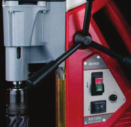
8 Before putting into operation Plug the cable into a suitable supply. Check the correct voltage! If you are using an extension cable please check if it is suitable for the machine`s rated input power! Attention: For vertical and overhead drilling work it is absolutely necessary to wear the enclosed safety belt. Putting into operation Position the drill bit over the drilling point. Switch the magnetic drilling unit on by pressing the red switch. The magnetic field that is created keeps the drilling unit clamped to the workpiece. Before drilling check if the magnetic drilling unit clamps safely to the workpiece. Magnetic drilling units with the possibilty of precise adjustment (see technical data) allow an exact positioning of the drill bit even after the electromagnet has been switched on. For this it is necessary to loosen the lever of the precise adjustment device. The drilling mechanism can now be moved and adjusted on the electromagnet. After the drill bit has been adjusted the lever is fastened and the adjusted position is fixed. With machines with more than one gear adjust the rotation speed of the engine according to the tool to be used. Attention: Change rotation speeds only when the drilling mechanism is not working! The speeds are indicated by a single or double symbols on the changeover switch. The changeover can be helped by gently turning the work spindle by hand. For drill drive units which also have electronic speed controllers, the speed and power (torque) can be continuously adjusted at the corresponding controller on the drill drive unit. Note: also read and follow the additional information provided under Drill drive type RS 0e. For drill drive units with electronic speed controllers, the speed is adjusted at the corresponding set wheel on the control panel of the drill stand. For drill drives with the forward and reverse feature (types RS 0e only) the direction is changed via the black switch on the control panel of the drill stand. Position R is for clockwise and Position L is for the anticlockwise rotation. Note: The direction of rotation must only be changed when the drill drive is switched off. The switch is for turning on the drilling mechanism (green light up ON). Please note: The drilling mechanism can only be started after the electromagnet has been switched on. Drill feed is made manually by moving the handles.to avoid overloading of the magnetic drilling unit or to avoid premature wear of the tool it is necessary to adjust the drilling pressure. After each cut chips and/or drilling cores have to be removed. Cooling/lubrication has to be made according to the tool used. Please take care to use not more cooling/lubrication paste than necessary and that it does not get into the drilling mechanism. After usage the magnetic drilling units should be stored in a vertical position so that the gear oil may spread evenly. Drillling unit RS0e Function and mode of effect of the electronic module. Essentially, the electronics have three main tasks to fulfil:. protecting the operator against accidents. securing a long service life of the drill drive and the tools. infinite speed adjustment to match the technical requirement in question An adjustable torque limitation set on the Power controller grants the operator accident protection to a very great extent and the greatest possible gentle treatment for the drill drive. In controller position -, the integrated electronics automatically switch off when the nominal torque is exceeded. In controller position, about 0. times the nominal torque becomes active, in controller position 7 about. times. The torques resulting in controller positions -7 are intended for cases of short-term overloads. In such cases of application, drill drive must be operated with increased care. If the pre-selected torque is exceeded in drilling, the drill drive is switched off by the electronics. The drill drive starts again by removing the load. If the drill drive does not start again immediately, the thermal overload protection has become effective at the same time. It prevents exceeding of the admissible coil temperature with large torques or a reduced speed. Switch the drill drive off on the combined motor switch. After sufficient cooling of the coil, work can be continued by pressing the on combined motor switch. After switching on again, we recommend operating the drill drive at top speed and idling for a short period, in order to achieve maximum cooling. The required speed can be set infinitely between minimum and maximum on the speed controller according to Diagram. Level 7 corresponds to the nominal speed of the switched transmission gear in question. The selected speed does not change under load, which has a very favourable effect on the service life of the tool. For drill drives with clockwise/anti-clockwise movement, the direction of rotation can be changed by means of a change-over switch. The change-over switch may only be operated with the drill drive at a standstill. The pre-selection of the size or the limitation of the torque is to be done taking the technical and industrial safety requirements in the implementation of the work task into account. 8
9 B B Drawing of drilling mechanism RS0
10 Drawing of drilling unit RS RS ch! Drawing of electrical system RS M- M M M MO A SL B M MO B B M M M+ M- MA B PR C C PR PR 80 MO MO A MO MO MO 79 MA 8 M MO 85 6 SL C C MA PR MA a MA a MA 86 7 MO MO MA a MA a 0
11 Drilling unit RS0 Machined body + brass plate 7 00 Spring plunger Pinion shaft 7 7 Star grip with threaded rod Bearing bowl 7 6 Safety ring Balance plate Threaded pin M5x Cylinder head screw M5 x Toothed disc 5. mm Hexagon socket screw Mx Cable gland Cool bottle 7 0 Lid for cool bottle Connection cooling Switch magnet Adapter for handle Hand lever compl Set screw with flat point M8x Guide rail 6 8 Cylinder head screw M5x Cylinder head screw Mx Cylinder head screw M8x Cylinder head screw M8x Magnet + fine adjustment compl Carriage Toothed rack 6 8 Cylinder head screw M6x Cylinder head screw M8x Drilling mechanism RS0 0 Motor cover Screw,9x Strain relief bushing 7 0 Carbon brush, cpl. 6.x0x8 L8F Cold-forming tapping screw ZMx Corrugated spring washer B 6 5 B Pocket brush holder, cpl Motor housing Pole ring, cpl Tapping screw C.9x Grooved dowel pin x Gearbox seal 6 50 Gear bearing plate Air guide ring Circlip / 6 59 Grooved ball bearing 600 RS Circlip 8/. 6 5 B Armature, cpl. - 5 V Grooved ball bearing 608 Z O-ring x Disc Shaft sealing ring 5x0x Work spindle Feather key A5x5x Grooved ball bearing 690 RS Connection cooling PT screw 50x5 7 00
12 Drilling mechanism RS0 55 Gear housing T piece Cylinder head screw Mx Spring plunger Ø Control button Grooved ball bearing 60 RS Adjusting washer 5/x Spindle wheel 5 teeth Circlip 5/ Grooved ball bearing Pressure piece M8x8 resilient Shaft with pinions Sleeve x7x Screw Mx Coupling bolts, cpl Intermediate wheel teeth Grease chamber bulkhead Feather key A5x5x Shaft for gear cluster teeth Gear cluster /0 teeth Needle sleeve HK Electrical system RS0 76 Magnet - 77 DIN M DIN M x Front cover Motor switch - 5 V Cables motor switch-magnet switch-plate 6 8 Circuitboard Back cover Cable motor switch-plate Motor cable Main cable - GB Main cable - USA 6 09
13 B 60 B Drawing of drilling mechanism RS5e
14 Drawing of drilling unit RS5e i für RS gleich! Drawing of electrical system RS5e M- M LR a LR a LR LR LR b LR b MO M MO A MO MO MO SP SP 8 M MO A MA 88 M SL MO B 9 M MO B B M C C M M+ M- MA PR blau B PR grün MP MP blau C C PR grün PR 5 PR 6 PR 78 PR PR 9 6 SL MA MA a MA a MA MP MP MP MP 9 MP MP SP SP MO MO LR LR a LR b LR a LR LR b MA a MA a
15 Drilling unit RS5e Machined body + brass plate 7 00 Spring plunger Pinion shaft 7 7 Star grip with threaded rod Bearing bowl 7 6 Safety ring Balance plate Threaded pin M5x Cylinder head screw M5 x Toothed disc 5. mm Hexagon socket screw Mx Cable gland Cool bottle 7 0 Lid for cool bottle Connection cooling Switch magnet Adapter for handle Hand lever compl Set screw with flat point M8x Guide rail 6 8 Cylinder head screw M5x Cylinder head screw Mx Cylinder head screw M8x Cylinder head screw M8x Magnet + fine adjustment compl Carriage Toothed rack 6 8 Cylinder head screw M6x Cylinder head screw M8x Drilling mechanism RS5e 0 Motor cap Screw.9x Tapping screw HC.9x 7 50 PCB - 5 V Strain relief bushing Carbon brush, cpl. 6.x0x8 L85F Cold-forming tapping screw ZMx Corrugated spring washer B 6 5 B Pocket brush holder, cpl Motor housing Pole ring, cpl Tapping screw C.9x Grooved dowel pin x 6 5 Gearbox seal 6 50 Gear bearing plate Air guide ring Circlip / Grooved ball bearing 600 RS Circlip 8/. 6 5 B Armature, cpl. - 5 V Grooved ball bearing 608 Z Press board disc Magnetic disc O-ring x Carbon support strand Disc Shaft sealing ring 5x0x
16 Drilling mechanism RS5e 55 Work spindle Feather key A5x5x Grooved ball bearing 690 RS Connection cooling PT screw 50x Gear housing T piece Cylinder head screw Mx Spring plunger Ø Control button Grooved ball bearing 60 RS Adjusting washer 5/x Spindle wheel 5 teeth Circlip 5/ Pressure piece M8x8 resilient Grooved ball bearing Screw Mx Sleeve x7x Coupling bolts, cpl Shaft with pinions Intermediate wheel teeth Grease chamber bulkhead Shaft for gear cluster teeth Feather key A5x5x Gear cluster /0 teeth Needle sleeve HK Electrical system RS5e 8 Magnet - 8 DIN M DIN M x Front panel Motor switch - 5 V L/R switch Speed controller Cable set motor switch/solenoid switch/circuit board 6 89 Circuit board Rear plate Cable set capacitor motor Motor cable Main cable - GB Main cable - USA
17 B 60 B Drawing of drilling mechanism RS6e
18 Drawing of drilling unit RS6e Drawing of electrical system RS6e 8 85 LR a LR a LR LR LR b LR b 8 M- MO M+ M MO A MO MO MO SP SP 8 M MO A 88 MA 88 M SL MO B 9 89 M MO SL MA 90 MA a MA a MA 9 B B M C C M M+ M- MA PR blau B PR grün MP MP blau C C PR grün PR 5 PR 6 PR 78 PR PR 9 6 MP MP MP MP 9 MP MP SP SP MO MO LR LR a LR b LR a LR LR b MA a MA a 8
19 Drilling unit RS6e Machined body + brass plate 7 00 Spring plunger Pinion shaft 7 7 Star grip with threaded rod Bearing bowl 7 6 Safety ring Balance plate Threaded pin M5x Cylinder head screw M5 x Toothed disc 5. mm Hexagon socket screw Mx Cable gland Cool bottle 7 0 Lid for cool bottle Connection cooling Switch magnet Adapter for handle Hand lever compl Set screw with flat point M8x Guide rail 6 8 Cylinder head screw M5x Cylinder head screw Mx Cylinder head screw M8x Cylinder head screw M8x Magnet + fine adjustment compl Carriage Toothed rack 6 8 Cylinder head screw M6x Cylinder head screw M8x Drilling mechanism RS6e 0 Motor cap Screw.9x Tapping screw HC.9x 7 50 PCB - 5 V Strain relief bushing Carbon brush, cpl. 6.x0x8 L85F Cold-forming tapping screw ZMx Corrugated spring washer B 6 5 B Pocket brush holder, cpl Motor housing Pole ring, cpl Tapping screw C.9x Grooved dowel pin x 6 5 Gearbox seal 6 50 Gear bearing plate Air guide ring Circlip / Grooved ball bearing 600 RS Circlip 8/. 6 5 B Armature, cpl. - 5 V Grooved ball bearing 608 Z Press board disc Magnetic disc O-ring x Carbon support strand Disc Shaft sealing ring 5x0x
20 Drilling mechanism RS6e 55 Work spindle Feather key A5x5x Grooved ball bearing 690 RS Connection cooling PT screw 50x Gear housing T piece Cylinder head screw Mx Spring plunger Ø Control button Grooved ball bearing 60 RS Adjusting washer 5/x Spindle wheel 5 teeth Circlip 5/ Pressure piece M8x8 resilient Grooved ball bearing Screw Mx Sleeve x7x Coupling bolts, cpl Shaft with pinions Intermediate wheel teeth Grease chamber bulkhead Shaft for gear cluster teeth Feather key A5x5x Gear cluster /0 teeth Needle sleeve HK Electrical system RS6e 8 Magnet DIN M DIN M x Front panel Motor switch - 5 V L/R switch Speed controller Cable set motor switch/solenoid switch/circuit board 6 89 Circuit board Rear plate Cable set capacitor motor Motor cable Main cable - GB Main cable - USA
21 0 9 8 B B B Drawing of drilling mechanism RS0e
22 Drawing of drilling unit RS0e r RS ich! Drawing of electrical system RS0e M- M MO M MO A MO MO MO SP SP 99 M MO A MA 0 M SL MO B M MO B B M M M+ M- MA B 6 C PR C MA C C PR MP MP MA a MA a MA 07 PR PR MP MP 8 06 SL MO MO SP SP MA a MA a
23 Drilling unit RS0e Machined body + brass plate 7 00 Spring plunger Pinion shaft 7 7 Star grip with threaded rod Bearing bowl 7 6 Safety ring Balance plate Threaded pin M5x Cylinder head screw M5 x Toothed disc 5. mm Hexagon socket screw Mx Cable gland Cool bottle 7 0 Lid for cool bottle Connection cooling Switch magnet Adapter for handle Hand lever compl Set screw with flat point M8x Guide rail 6 8 Cylinder head screw M5x Cylinder head screw Mx Cylinder head screw M8x Cylinder head screw M8x Magnet + fine adjustment compl Carriage Toothed rack 6 8 Cylinder head screw M6x Cylinder head screw M8x Drilling mechanism RS0e 0 Motor housing 7 00 Pole ring, cpl B Pocket brush holder, cpl Corrugated spring washer B 6 5 Cold-forming tapping screw ZMx 6 50 Carbon brush, cpl Nut M Flexicon clip Screw Mx PCB - 5 V Tapping screw HC. x Screw.9x Cap Grease chamber bulkhead 7 0 O-ring 06x 7 0 Gear bearing plate Grooved dowel pin 5x Air guide ring, cpl Circlip / Grooved ball bearing 600 RS Circlip 8/. 6 5 B Armature, cpl. - 5 V Grooved ball bearing 6000 Z Ring magnet Disc made of press board Bearing cap Carbon support strand 7 505
24 Drilling mechanism RS0e 55 Sealing washer Shaft sealing ring x55x Work spindle Circlip 55/ Feather key B6x6x Grooved ball bearing 6006 RS Connection cooling PT screw 50x Gear housing T piece Cylinder head screw Mx O-ring 6x Seeger snap ring SB Spring plunger Ø Control button Grooved ball bearing 6005 RS Adjusting washer 5/5x Spindle wheel Circlip / Grooved ball bearing B Coupling, cpl Intermediate shaft Disc spring 8/.x Coupling half Feather key, hardened A5x5x Coupling wheel Thrust washer Adjusting washer x Thrust washer Lock washer Needle sleeve HK Needle bearing RNA Washer for needle bearing Intermediate shaft Feather key, hardened A5x5x Intermediate wheel Gear cluster Coupling bolts Hexagon socket screw Mx Sleeve Intermediate shaft Feather key A5x5x Electrical system RS0e 96 Magnet - 97 DIN M DIN M x Front cover Magnet switch - 5 V Speed controller Cables motor switch-magnet switch-plate 6 0 Circuitboard Back cover Cables capacitor motor Motor cable Main cable - GB Main cable - USA 6 09
25 B B B Drawing of drilling mechanism RS0e
26 Drawing of drilling unit RS0e r RS ich! Drawing of electrical system RS0e M- M LR a LR a SP LR LR SP PO PO MO MO LR a LR b LR b 5 MO M MO A MO MO MO SP SP PO PO LR M 00 MO A MA 05 M SL MO 09 B B B M C C M M+ M M- MO MA PR blau B PR MP MP grün MP 5 MP 6 blau C C PR 5 PR 6 PR 7 PR 8 PR 9 PR 0 MA 6 MA a MA a SL MA a MA a MA grün 0 MP MP MP MP 5 MP MP 6 MP MP 8 LR b LR LR b LR a 6
27 Drilling unit RS0e Machined body + brass plate 7 00 Spring plunger Pinion shaft 7 7 Star grip with threaded rod Bearing bowl 7 6 Safety ring Balance plate Threaded pin M5x Cylinder head screw M5 x Toothed disc 5. mm Hexagon socket screw Mx Cable gland Cool bottle 7 0 Lid for cool bottle Connection cooling Switch magnet Adapter for handle Hand lever compl Set screw with flat point M8x Guide rail 6 8 Cylinder head screw M5x Cylinder head screw Mx Cylinder head screw M8x Cylinder head screw M8x Magnet + fine adjustment compl Carriage Toothed rack 6 8 Cylinder head screw M6x Cylinder head screw M8x Drilling mechanism RS0e 0 Motor housing 7 00 Pole ring, cpl B Pocket brush holder, cpl Corrugated spring washer B 6 5 Cold-forming tapping screw ZMx 6 50 Carbon brush, cpl Nut M Flexicon clip Screw Mx PCB - 5 V Tapping screw HC. x Screw.9x Cap Grease chamber bulkhead 7 0 O-ring 06x 7 0 Gear bearing plate Grooved dowel pin 5x Air guide ring, cpl Circlip / Grooved ball bearing 600 RS Circlip 8/. 6 5 B Armature, cpl. - 5 V Grooved ball bearing 6000 Z Ring magnet Disc made of press board Bearing cap Carbon support strand
28 Drilling mechanism RS0e 56 Shaft sealing ring x55x Work spindle Circlip 55/ Feather key B6x6x Grooved ball bearing 6006 RS Connection cooling PT screw 50x Gear housing T piece Cylinder head screw Mx O-ring 6x Seeger snap ring SB Spring plunger Ø Control button Grooved ball bearing 6005 RS Adjusting washer 5/5x Spindle wheel Circlip / Grooved ball bearing B Coupling, cpl Intermediate shaft Disc spring 8/.x Coupling half Feather key, hardened A5x5x Coupling wheel Thrust washer Adjusting washer x Thrust washer Lock washer Needle sleeve HK Needle bearing RNA Washer for needle bearing Intermediate shaft Coupling bolts Feather key A6x6x Gear cluster Gear cluster Coupling bolts Hexagon socket screw Mx Sleeve Intermediate shaft Feather key A5x5x Electrical system RS0e 97 Magnet - 98 DIN M DIN M x Front panel Motor switch - 5 V L/R switch Speed controller Torque controller - 5 V Cable set motor switch/solenoid switch/circuit board 6 06 Circuit board Rear plate Cable set capacitor motor Motor cable Main cable - GB Main cable - USA
29 Connection diagramm RS0, RS5e, RS0e Netz / Net PE L L a b MA M M MO B ~ ~ + - U < i A B M+ M- M ~ PE Drilling Bohrantrieb mechanism Haftmagnet Clamping force 9
30 Guarantee: The Manufacturer default warranty period is months after date of delivery. Proof is the invoice. Condition is that the machine has been used, maintained and cleaned correctly and that no repairs by others have been made. The guarantee is limited to repairs free of charge or replacements of the damaged parts that are caused by material defects or production faults. Parts that have been damaged by normal wear or repairs made by oneself or others are not subject to this guarantee. This guarantee is only valid if the correct tools, original accessories and spare parts have been used. All other claims are excluded, i.e. RUKO is not liable for direct or indirect defects, damages caused by defects, losses or costs that may arise from the use or the impossibility to use the machine for a certain purpose. Tacit assurances concerning the use or aptability for a certain purpose are not possible. If a defect is noted the machine has to be sent to RUKO GmbH as quickly as possible for repair. All earlier verbal or written guarantee declarations are replaced by the above mentioned guarantee. Declaration of conformity: We declare in sole responsibility that the product sold by us is in accordance with the following technical norms or normative documents: EN : 00 EN : 997 EN : 998 EN / according to the regulations stipulated in the directives 89 / 6 / EWG (rather EMVG) 7 / / EWG (Low Voltage Directive), 98 / 7 / EG (Machine Directive) The description of operation is described in the operation instructions. Josef Ruppert Management RUKO GmbH Precision tools, Robert-Bosch-Straße 7-, D-7088 Holzgerlingen, Germany 0
31

70 / 6800-0 Internet:")


32 RUKO GmbH Precision tools Robert-Bosch-Straße Holzgerlingen Germany Tel.: +9(0)70 / Internet: info@ruko.de Export sales Tel.: +9(0)70 / / 8 / 85 / 790 Fax. +9(0)70 / / 66 All rights reserved. This catalogue is protected by copyright law and remains solely our property. We reserve the right to make changes to technical data. Images are non-binding. Liability for printing errors is excluded. This catalogue invalidates any previous editions. No. 80 / 6. Edition October 06 english
BASICline. USe InStrUCtIon 115V RS5e - RS40e
 BASICline USe InStrUCtIon 5V RS5e - RS0e Contents Page technical data Security instructions Assembling, Application, Maintenance 5 Putting into operation 6 Drawing of drilling unit drilling mechanism rs5e
Spare part price list MAB 825 Motor
 MAB 825 Motor BDS Maschinen GmbH -Errors and omissions excepeted!- 02.09.2016 MAB 825 Motor Pos. No. Article no. Description pc. 1.1.1 5013911 Armature 110V 1 1.1.2 5050061 Armature 230 V 1 1.2.1 5012551
Spare part list 2015 MAB 845 Motor Drawing
 MAB 845 Motor Drawing MAB 845 Motor Article no. Description pc 1.1.1 5013911 Armature 110V 1 1.1.2 5050061 Armature 230V 1 1.2.1 5012551 Field coil 110V 1 1.2.2 5011611 Field coil 230V 1 1.3.1 5050051
Spare part list 2014 MAB 1300 Motor Drawing
 MAB 1300 Motor Drawing MAB 1300 Motor Article no. Description pc 1.1.1 5013931 Armature 110V 1 1.1.2 5013921 Armature 230V 1 1.2 5011301 Ball bearing 6000 2Z 1 1.3 5013941 Seal ring 10x14x1 1 1.4 5013951
Spare part list 2015 MAB 825 Motor Drawing
 MAB 825 Motor Drawing MAB 825 Motor Pos. No. Article no. Description pc 1.1.1 5013911 Armature 110V 1 1.1.2 5050061 Armature 230 V 1 1.2.1 5012551 Field coil 110 V 1 1.2.2 5011611 Field coil 230V 1 1.3.1
USER MANUAL TO REDUCE THE RISK OF INJURY USER MUST READ AND UNDERSTAND INSTRUCTION MANUAL ECO.50-T. Magnetic Drilling Machine
 USER MANUAL TO REDUCE THE RISK OF INJURY USER MUST READ AND UNDERSTAND INSTRUCTION MANUAL ECO.50-T Magnetic Drilling Machine SERIAL NO. DATE OF PURCHASE 1 - Table of Contents 1 Table of Contents page 1
USER MANUAL TO REDUCE THE RISK OF INJURY USER MUST READ AND UNDERSTAND INSTRUCTION MANUAL ECO.100/4. Magnetic Drilling Machine
 USER MANUAL TO REDUCE THE RISK OF INJURY USER MUST READ AND UNDERSTAND INSTRUCTION MANUAL ECO.100/4 Magnetic Drilling Machine SERIAL NO. DATE OF PURCHASE 1 - Table of Contents 1 Table of Contents page
MAGNETIC-STAND DRILLING MACHINES. profiline
 MAGNETIC-STAND DRILLING MACHINES profiline Comparison of technical data RS4 - RS40e - The New RS GENERATION! RS20 / RSM20 Technical data RS4 RS5e RS10 RS20 RSM20 Mag. clamping force: 10.000 N 10.000 N
Disc Grinder Model G 18MR G 23MR G 23MRU
 Disc Grinder Model G 18MR G 23MR G 23MRU Handling instructions G23MR NOTE: Before using this Electric Power Tool, carefully read through these HANDLING INSTRUCTIONS to ensure efficient, safe operation.
INSTRUCTION MANUAL ANGLE GRINDER PT W
 INSTRUCTION MANUAL ANGLE GRINDER PT50360 4½ INCHES 120V 60Hz 600W 5A 12,000 rpm C US Note : Before operating this tool, read this manual and follow all safety rules and operating instructions. This electric
MAB 525 MOTOR BREAKDOWN
 PARTS BREAKDOWN Model #: MAB 525 Bulletin #: 08-2011 MAB 525 MOTOR BREAKDOWN Page 1 of 5 PARTS BREAKDOWN Model #: MAB 525 Bulletin #: 08-2011 MAB 525 MOTOR PARTS LIST 1 5010581 Screw 4,8 x 45 2 5010911
MAB 485 MAB 485 MOTOR BREAKDOWN
 MAB 485 MAB 485 MOTOR BREAKDOWN 22 23 24 45 46 48 49 47 32 20 21 26 25 27 10 11 17 19 18 34 31 29 30 28 16 31 31 15 2 33 3 4 13 1 40 39 50 14 5 38 37 44 35 41 6 7 8 36 51 9 43 42 05/2006 For a complete
MAB 1300 MOTOR BREAKDOWN
 WIRING DIAGRAM Date: 9/14/2015 MAB 1300 MOTOR BREAKDOWN Page 1 of 6 WIRING DIAGRAM Date: 9/14/2015 MAB 1300 MOTOR PARTS LIST 1 5013921 Armature 220-240V 1A 5013931 Armature 110 V 2 5011301 Ball bearing
DR. BENDER GmbH Innovative Elektrowerkzeuge. Manual for 115 V
 DR. BENDER GmbH Innovative Elektrowerkzeuge Manual for drilling motor BBM 33 L extra 115 V Valid from 07.2004 Art.-Nr. 200515 Subject to alterations All rights reserved DR. BENDER GmbH D-75382 Althengstett
OWNER S OPERATING MANUAL
 OWNER S OPERATING MANUAL ARC 140 AMP WELDER TABLE OF CONTENTS Page Safety instructions 3-4 Inverter Arc Welder 5 Welder Information 5 Arc 140 AMP welder set up 6 Assembly instructions 6 Operation 7 Welding
GRIMAX 50,75,100,150 S - BRAKE
 B E L T - G R I N D E R S GRIMAX 50,75,100,150 S - BRAKE Table of contents 1. Transport and handling 5 1.1 Transport 5 1.2 Handling 5 1.3 Placing 5 2. Directions 6 2.1 Operation 6 2.2 Safety rules for
Cordless High Speed Drill
 ENGLISH Cordless High Speed Drill MODEL 6503D 00039 I N S T R U C T I O N M A N U A L WARNING: For your personal safety, READ and UNDERSTAND before using. SAVE THESE INSTRUCTIONS FOR FUTURE REFERENCE.
1200W CaR PoliSheR en RS4900
 1200W Car Polisher RS4900 RS4900 8 1 2 7 3 4 5 6 A B flat nozzle C D E F 1200W Car Polisher RS4900 G H flat nozzle I J K L 4 1200W Car Polisher COMPONT LIST 1 2 3 4 5 6 7 Variable speed control Switch
Cutlass Fasteners, Inc. 83 Vermont Ave., Unit 6, Warwick, RI Tel: (401) Fax: (401) cutlass-studwelding.com
 Fax: (401) cutlass-studwelding.com") MODEL : BANTAM C8 PART NO. : 602-325P SERIAL NO. : PLEASE READ THIS OPERATION AND MAINTENANCE MANUAL CAREFULLY BEFORE USING YOUR NEW CUTLASS STUD WELDER. COPYRIGHT CFI 2009 email: sales@ PAGE - 1 - WARRANTY
MODEL : BANTAM C8 PART NO. : 602-325P SERIAL NO. : PLEASE READ THIS OPERATION AND MAINTENANCE MANUAL CAREFULLY BEFORE USING YOUR NEW CUTLASS STUD WELDER. COPYRIGHT CFI 2009 email: sales@ PAGE - 1 - WARRANTY
PRODUCT MANUAL TILE CUTTING MACHINE. . Operation. Parts List and Diagram SPECIFICATIONS CAUTION:
 FLORCRAFTT TM PRODUCT MANUAL SKU NUMBER 709-4242 SERIAL NUMBER: CAUTION: FOR YOUR OWN SAFETY READ INSTRUCTION MANUAL COMPLETELY AND CAREFULLY BEFORE OPERATING THIS 7 TILECUTTING MACHINE SPECIFICATIONS
Cutlass Fasteners, Inc. 83 Vermont Ave., Unit 6, Warwick, RI Tel: (401) Fax: (401) cutlass-studwelding.com
 Fax: (401) cutlass-studwelding.com") MODEL : BANTAM C8 BANTAM C10 PART NO. : 602-325A 602-343A SERIAL NO. : PLEASE READ THIS OPERATION AND MAINTENANCE MANUAL CAREFULLY BEFORE USING YOUR NEW CUTLASS STUD WELDER. COPYRIGHT CFI 2009 email: sales@
MODEL : BANTAM C8 BANTAM C10 PART NO. : 602-325A 602-343A SERIAL NO. : PLEASE READ THIS OPERATION AND MAINTENANCE MANUAL CAREFULLY BEFORE USING YOUR NEW CUTLASS STUD WELDER. COPYRIGHT CFI 2009 email: sales@
Subject to change. USERS MANUAL Art.nr. CDM6026 PCD-2400I. NiCd
 UK Subject to change UK USERS MANUAL Art.nr. CDM02 PCD-2400I NiCd 040-2 4 1 2 4 R L EXPLODED VIEW 3 Fig. A Fig. D B 1 2 Fig. B Fig. E 3 10 11 SPARE PARTS LIST PCD-2400I A Fig. C 3 Fig. F REF NR DESCRIPTION
Disc Grinder PDA-100H. Handling Instructions. Read through carefully and understand these instructions before use.
 Disc Grinder PDA100H Handling Instructions Read through carefully and understand these instructions before use. 1 2 4 6 8 1 2 3 4 5 6 7 9 0 8 L K I G 1 3 5 7 15 ~30 A B 1 A D 5 9 8 B C 0 1 2 J 4 5 8 0
3-Pt. Quick Hitch. Owner s Manual
 3-Pt. Quick Hitch Owner s Manual WARNING: Read carefully and understand all ASSEMBLY AND OPERATION INSTRUCTIONS before operating. Failure to follow the safety rules and other basic safety precautions may
INSTRUCTION MANUAL. Cordless Angle Drill XAD01
 INSTRUCTION MANUAL Cordless Angle Drill XAD0 0474 ENGLISH (Original instructions) SPECIFICATIONS Model XAD0 Capacities Steel 0 mm (3/8") Wood 25 mm (") No load speed (RPM) 0 -,800 /min Overall length 34
Hydraulic Impact Wrench Type
 M a s c h i n e n f a b r i k G m b H Hydraulic Impact Wrench Type 6 1520 0010 Illustration can differ from the original Operation and Maintenance Manual 615200010_en_Version_03 Page 1 of 19 TECHNICAL
Electric Chainsaw Sharpener With Bar Mount
 Electric Chainsaw Sharpener With Bar Mount Owner s Manual WARNING: Read carefully and understand all ASSEMBLY AND OPERATION INSTRUCTIONS before operating. Failure to follow the safety rules and other basic
DR. BENDER GmbH Innovative Elektrowerkzeuge. Manual for drilling motor EBL V
 DR. BENDER GmbH Innovative Elektrowerkzeuge Manual for drilling motor EBL 33 230 V Valid from 09.2004 Art.-Nr. 200662 Subject to alterations All rights reserved DR. BENDER GmbH D-75382 Althengstett Tel
frame, spindle case dated: 01/17
 frame, spindle case dated: 01/17 1 Powered by TCPDF (www.tcpdf.org) frame, spindle case dated: 01/17 Item no. Description Article no. Quantity 1 Caution sticker RO 87080 1 2 Caution plate RO 87081 1 3
Instruction Manual 4.0V Li-Ion Screwdriver. Part #: ECLIPSE ENTERPRISES, INC Chula Road, Amelia Court House, VA 23002, U.S.
 Instruction Manual 4.0V Li-Ion Screwdriver Part #: 902-588 ECLIPSE ENTERPRISES, INC. 13302 Chula Road, Amelia Court House, VA 23002, U.S.A 2 3 Intended use Your ECLIPSE ENTERPRISES, INC. 902-588 screwdriver
MODEL EGA200 OWNERS MANUAL
 3/8 RATCHET WRENCH MODEL EGA200 OWNERS MANUAL www.eaglecompressor.com 1-800-551-2406 READ THE ENTIRE MANUAL BEFORE PUTTING THIS TOOL IN SERVICE Limited Air Tool Warranty Wood Industries, Inc. warrants
Angle Grinder Holder
 Angle Grinder Holder Owner s Manual WARNING: Read carefully and understand all ASSEMBLY AND OPERATION INSTRUCTIONS before operating. Failure to follow the safety rules and other basic safety precautions
14.4 CORDLESS DRILL ASSEMBLY AND OPERATING INSTRUCTIONS
 14.4 CORDLESS DRILL 40209 ASSEMBLY AND OPERATING INSTRUCTIONS 3491 Mission Oaks Blvd., Camarillo, CA 93011 Visit our Web site at http://www.harborfreight.com Copyright 2002 by Harbor Freight Tools. All
24 Volt - 3/8" Cordless Impact Wrench
 24 Volt - 3/8" Cordless Impact Wrench INSTRUCTION MANUAL Item # 3994040 IMPORTANT SAFETY INSTRUCTIONS WARNING: When using electrical equipment such as this, basic safety precautions should always be followed
INSTRUCTION MANUAL FOR THE THERMOCOUPLE ATTACHMENT UNIT (TAU)
") INSTRUCTION MANUAL FOR THE THERMOCOUPLE ATTACHMENT UNIT (TAU) Model Number: 41756 (100 125Vac) 41757 (220 240Vac) Manufactured in the United Kingdom CONTENTS Chapter Page Specification 3 What the TAU does
INSTRUCTION MANUAL FOR THE THERMOCOUPLE ATTACHMENT UNIT (TAU) Model Number: 41756 (100 125Vac) 41757 (220 240Vac) Manufactured in the United Kingdom CONTENTS Chapter Page Specification 3 What the TAU does
Manual Tire Changing Station
 Manual Tire Changing Station Owner s Manual WARNING: Read carefully and understand all ASSEMBLY AND OPERATION INSTRUCTIONS before operating. Failure to follow the safety rules and other basic safety precautions
Heavy-Duty SDS Max Rotary Hammer Drill. Owner s Manual
 Heavy-Duty SDS Max Rotary Hammer Drill Owner s Manual WARNING: Read carefully and understand all ASSEMBLY AND OPERATION INSTRUCTIONS before operating. Failure to follow the safety rules and other basic
ORIGINAL INSTRUCTIONS
 OPERATION & MAINTENANCE INSTRUCTIONS CBB200 Shown here BUFFER/POLISHER MODEL NO: CBB150, CBB200 PART NO: 6500485, 6500490 ORIGINAL INSTRUCTIONS LS0818 - ISS 1 INTRODUCTION Thank you for purchasing this
DX 6 L DOLPHIN. DR. BENDER GmbH Innovative Elektrowerkzeuge. Manual for drilling motor 400 V 3~
 DR. BENDER GmbH Innovative Elektrowerkzeuge Manual for drilling motor DX 6 L DOLPHIN 400 V 3~ Valid from 09.2004 Art.-Nr. 200679 Subject to alterations All rights reserved DR. BENDER GmbH D-75382 Althengstett
Manual Chain Hoist. Owner s Manual
 Manual Chain Hoist Owner s Manual WARNING: Read carefully and understand all ASSEMBLY AND OPERATION INSTRUCTIONS before operating. Failure to follow the safety rules and other basic safety precautions
ABACO MACHINES OPERATION MANUAL STONE/STEEL/GLASS/WOODS LIFTER (ASSGWL20) ABACO MACHINES (USA)
 ABACO MACHINES (USA)") ABACO MACHINES OPERATION MANUAL STONE/STEEL/GLASS/WOODS LIFTER (ASSGWL20) ABACO MACHINES (USA) 14508 S. Garfield Ave., Paramount, CA 90723, USA Tel : 310-532-0366 Fax : 310-532-99 Email : sales@abacomachines.com
ABACO MACHINES OPERATION MANUAL STONE/STEEL/GLASS/WOODS LIFTER (ASSGWL20) ABACO MACHINES (USA) 14508 S. Garfield Ave., Paramount, CA 90723, USA Tel : 310-532-0366 Fax : 310-532-99 Email : sales@abacomachines.com
6 x 10 Belt Disc Sander
 6 x 10 Belt Disc Sander FOR HELP OR ADVISE ON THIS PRODUCT PLEASE CALL OUR CUSTOMER SERVICE HELP LINE : 01509 500400 THE MANUFACTURER RESERVES THE RIGHT TO ALTER THE DESIGN OR SPECIFICATION TO THIS PRODUCT
Repair Manual and Spare Parts List
 Hydraulic Drive Unit Type Techn. Doc. No. 362 and Accessories for Pipe Cutting Machine Darstellung kann vom Original abweichen Repair Manual and 580067000_Inst_en_Version_03 Repair General In general,
SIP Direct Drive Oil-Lube Air Compressors - Operating & Maintenance Instructions
 SIP Direct Drive Oil-Lube Air Compressors - Operating & Maintenance Instructions Please read and fully understand the instructions in this manual before operation. Keep this manual safe for future reference.
ECSS. Electric Chain Saw Chain Sharpener Assembly & Operating Instructions
 ECSS Electric Chain Saw Chain Sharpener Assembly & Operating Instructions READ ALL INSTRUCTIONS AND WARNINGS BEFORE USING THIS PRODUCT. SAVE THESE INSTRUCTIONS FOR FUTURE REFERENCE. This manual provides
eclipse Instruction Manual 4.0V Li-Ion Screwdriver Part #:
 eclipse Instruction Manual 4.0V Li-Ion Screwdriver Part #: 902-588 Test Equipment Depot - 800.517.8431-99 Washington Street Melrose, MA 02176 TestEquipmentDepot.com Test Equipment Depot - 800.517.8431-99
18 GAUGE FLOORING STAPLER. Models: /13
 18 GAUGE FLOORING STAPLER Models: 7560 CALIFORNIA PROPOSITION 65 WARNING: You can create dust when you cut, sand, drill or grind materials such as wood, paint, metal, concrete, cement, or other masonry.
Drive Unit e-drive1. Installation instructions 04/2014. English translation of the original German installation instructions
 Drive Unit e-drive1 Installation instructions 04/2014 English translation of the original German installation instructions Contents Foreword... 3 Availability... 3 Structural features in the text... 3
16 Inch Surface Cleaner
 16 Inch Surface Cleaner Owner s Manual WARNING: Read and understand all instructions, warnings, and cautions before using this product. Failure to follow the instructions, warnings, and cautions may result
Yellow & Green connections to ensure that none is loose.
 instructions for: power belt sander model no: SM100 Thank you for purchasing a Sealey product. Manufactured to a high standard this product will, if used according to these instructions and properly maintained,
RB V (# 25821)
") RB-206-3 230 V (# 25821) Ref. 1 Rotor compl. 65356 2 Bearing Cap 65346 3 Stator compl. 65366 4 Air Guide Ring 65376 5 Motor Housing RAL 2002 65386 6 Brush Holder 65396 7 Contact Washer 64796 8 Magnetic
RB-206-3 230 V (# 25821) Ref. 1 Rotor compl. 65356 2 Bearing Cap 65346 3 Stator compl. 65366 4 Air Guide Ring 65376 5 Motor Housing RAL 2002 65386 6 Brush Holder 65396 7 Contact Washer 64796 8 Magnetic
PT-1441 Cordless Drill Driver 14.4V User s Manual
 PT-1441 Cordless Drill Driver 14.4V User s Manual 1 st Edition, 2009 2009 Copy Right by Prokit s Industrial Co., Ltd. Please read this handbook carefully before using the tool General Safety Rules WARNING
W6VB3 W8VB2. Handling instructions
 Screw Driver Model W 6VM W 6V4 W 6VA4 W 6VB3 W 8VB2 Handling instructions W6VM W6V4 W6VA4 W6VB3 W8VB2 Note: Before using this Electric Power Tool, carefully read through these HANDLING INSTRUCTIONS to
Sawhorse with Chainsaw Holder
 Sawhorse with Chainsaw Holder Owner s Manual Chainsaw not included. WARNING: Read carefully and understand all ASSEMBLY AND OPERATION INSTRUCTIONS before operating. Failure to follow the safety rules and
HST -LS Interlocking device (Translation of Original Manual)
") Installation and Operating Manual for Components HST -LS Interlocking device (Translation of Original Manual) HST-LS Ident.-No.: 10268 HST-LS Ident.-No.: 10269 HST-LS, pictured Ident-Nr. 10269 The image
Installation and Operating Manual for Components HST -LS Interlocking device (Translation of Original Manual) HST-LS Ident.-No.: 10268 HST-LS Ident.-No.: 10269 HST-LS, pictured Ident-Nr. 10269 The image
Repair Manual and Spare Parts List
 Pneumatic Drive Unit Type Techn. Doc. No. 352 and Accessories for Pipe Cutting Machine Darstellung kann vom Original abweichen Repair Manual and 580027000_Inst_en_Version_02 Repair General In general,
MBQ100 Assembly & Parts List
 MBQ100 Assembly & Parts List 5 32 1 QUICK RELEASE ARBOR ASSEMBLY INLUDES ITEMS 33 TO 41 12 11 CONTROL PANEL ASSEMBLY INCLUDES ITEMS 47 TO 57 3 7 7 4 31 2 27 5 43 4 42 44 45 5 59 9 10 0 13 1 17 ITEM NO
DISC BRAKE CALIPER TOOL SET
 DISC BRAKE CALIPER TOOL SET 40732 ASSEMBLY AND OPERATING INSTRUCTIONS Diagrams within this manual may not be drawn proportionally. Due to continuing improvements, actual product may differ slightly from
Linear Luminaire for Fluorescent Lamps
 Linear Luminaire for Fluorescent Lamps Operating instructions Additional languages www.stahl-ex.com General Information Contents 1 General Information...2 1.1 Manufacturer...2 1.2 Information regarding
Instruction Manual CORDLESS DRILL & DRIVER 18V. Model SROM 1170
 Instruction Manual CORDLESS DRILL & DRIVER 18V Model SROM 1170 Product Features: Dear Valued Customer, Thank you for purchasing this Samson Power Tool. We are dedicated to providing quality Samson Power
Cordless Screwdriver
 ENGLISH Cordless Screwdriver MODEL 6796D MODEL 6796FD MODEL 6797D MODEL 6797FD MODEL 6798D MODEL 6798FD 00260 I N S T R U C T I O N M A N U A L WARNING: For your personal safety, READ and UNDERSTAND before
MBQ100 Assembly & Parts List
 MBQ100 Assembly & Parts List 32 1 23 QUICK RELEASE ARBOR ASSEMBLY INLUDES ITEMS 33 TO 41 19 12 11 3 24 31 4 5 25 4 42 1 44 2 45 2 2 9 10 2 13 1 29 15 1 ITEM NO PART NO DESCRIPTION QTY 1 M0005BLU ORA MT50
SINGLE SPEED MODELS SEMI-AUTO FEED MODELS 2-SPEED MODELS 4 SPEED VARIABLE MOTOR SPEED MODELS
 SINGLE SPEED MODELS SEMI-AUTO FEED MODELS 2-SPEED MODELS 4 SPEED VARIABLE MOTOR SPEED MODELS ORIGINAL OPERATING INSTRUCTIONS SAVE THESE INSTRUCTIONS FOR FUTURE REFERENCE Warning: For tools equipped with
Ex m Solenoid Operator Type 0519
 nass magnet GmbH Eckenerstrasse 4-6 D-30179 Hannover Doc. No. 113-720-0002 Revision No. 2 01.06.2015 Ex m Solenoid Operator Type 0519 Operating Instructions Dear Customer! To ensure the function and for
MAB 150 MOTOR PARTS LIST
 MAB 150 MOTOR PARTS LIST 1 50 1324 1 Cap for motor housing 2 50 1325 1 Screw M5 x 20 3 50 1297 1 Motor housing 4 50 1321 1 Carbon brush holder compl. 5 50 1322 1 Carbon brush 6,4 x 12,5 x 19 6 50 1319
Pneumatic Corner Drill
 Maschinenfabrik GmbH Pneumatic Corner Drill Type 2 1602 0030 Illustration can differ from the original Operation and Maintenance Manual Compiled: 31.07.08 216020030_en.doc Page 1 of 12 TECHNICAL SPECIFICATION
Spare part list 2014 MAB 840 Motor Drawing
 MAB 840 Motor Drawing MAB 840 Motor 1.1.1 5011731 Armature 110V 1 1.1.2 5011721 Armature 230V 1 1.2.1 5012551 Field coil 110V 1 1.2.2 5011611 Field coil 230V 1 1.3 5011631 Motor housing 2 1.4 5011091 Air
4 in 1 POWER STATION Model: 7226
 Please carefully read and save these instructions before attempting to assemble, maintain, install, or operate this product. Observe all safety information to protect yourself and others. Failure to observe
Bowl feeder WV401-1 / Translation of operating and installation instructions
 Bowl feeder WV401-1 / 402-1 Translation of operating and installation instructions Copyright by Afag GmbH This operation instruction applies to: Bowl feeder WV401-1 Bowl feeder WV402-1 Type 230 V / 50
Disc Grinder Model G 18SCY G 18SEY G 18UBY G 23SCY G 23SEY G 23UBY
 Disc Grinder Model G 18SCY G 18SEY G 18UBY G 23SCY G 23SEY G 23UBY Handling instructions G23SEY NOTE: Before using this Electric Power Tool, carefully read through these HANDLING INSTRUCTIONS to ensure
MANUAL. Single charger
 MANUAL Single charger HST-PR-2830 & HST-PR-2830USA for HS-Technik batteries HST-PR-18xx HST-PR-14xx issue date: November 2016 Table of contents Page 1. Basic information...3 1.1. Purpose of this document...3
1/4 Die Grinder. Please read and fully understand the instructions in this manual before operation. Keep this manual safe for future reference
 Please dispose of packaging for the product in a responsible manner. It is suitable for recycling. Help to protect the environment, take the packaging to the local amenity tip and place into the appropriate
CORDLESS 18V CIRCULAR SAW KIT
 CORDLESS 8V CIRCULAR SAW KIT 374 ASSEMBLY and OPERATING INSTRUCTIONS www.harborfreight.com 349 Mission Oaks Blvd., Camarillo, CA 930 Copyright 997 by Harbor Freight Tools. All rights reserved. No portion
HYDRAULIC SPRING COMPRESSOR SET
 HYDRAULIC SPRING COMPRESSOR SET Model 47890 ASSEMBLY and OPERATING INSTRUCTIONS 3491 Mission Oaks Blvd., Camarillo, CA 93011 Visit our Web site at http://www.harborfreight.com Copyright 2002 by Harbor
SPARE PARTS LIST WALL SAW WSE1621
 SPARE PARTS LIST WALL SAW Index 000 EN Spare Parts List 10999154 de / 01.11.2018 How to use the spare parts list The spare parts list is not intended as instructions for assembly or dismantling work. It
4V LITHIUM-ION SCREWDRIVER OWNER S OPERATING MANUAL
 CSD-4107BG 4V LITHIUM-ION SCREWDRIVER OWNER S OPERATING MANUAL Your screwdriver has been engineered and manufactured to our high standard for dependability, ease of operation, and operator safety. When
Spare parts list Pentruder Modular Drilling System
 Spare parts list Pentruder Modular Drilling System Pentruder Modular Drilling System, Column CN-0.5; 1.2; 1.5 F/M Page CN-F/M Pentruder Modular Drilling System, Column CN-0.5; 1.2; 1.5 F/M Page CN-F/M
TABLE OF CONTENTS. Section 1 - Important Safety Instructions Section 2 - Grounding Instructions Section 3 - Operator Cautions...
 Light Tools - DC Screwdriver Operation & Maintenance Manual For Models: SKD-2000L/UL/B, SKD-2200L/UL/B, SKD-2300L/UL/B SKD-5200L/UL/B, SKD-5200P/UL/B SKD-5300L/UL/B, SKD-5300P/UL/B Dixon Automatic Tool
OWNER S OPERATING MANUAL
 OWNER S OPERATING MANUAL MIG 100 GASLESS WELDER TABLE OF CONTENTS Page Safety instructions 3-4 MIG Welders 5 Welder Information 5 Gasless welder set up 6 Operation 6-10 Troubleshooting Guide 11-12 Spare
RAUTOOL G2 BATTERY HYDRAULIC TOOL KIT PRODUCT INSTRUCTIONS. Construction Automotive Industry
 RAUTOOL G2 BATTERY HYDRAULIC TOOL KIT PRODUCT INSTRUCTIONS www.rehau.com Construction Automotive Industry TABLE OF CONTENTS Safety Information... 3 Items Supplied............................................4
SAFETY AND OPERATING MANUAL. Lithium-Ion cordless hammer drill WX372 WX372.1 WX372.9
 SAFETY AND OPERATING MANUAL 2 Original Instructions General Power Tool Safety Warnings WARNING: Read all safety warnings and all instructions. Failure to follow the warnings and instructions may result
Operator's manual. TruTool F 140 (1A1) english
 english") Operator's manual TruTool F 140 (1A1) english Table of contents 1. Safety...3 2. Description...5 2.1 Intended use...6 2.2 Technical data of the TruTool F 140...7 2.3 Lock seams...8 3. Tool assembly...10
Operator's manual TruTool F 140 (1A1) english Table of contents 1. Safety...3 2. Description...5 2.1 Intended use...6 2.2 Technical data of the TruTool F 140...7 2.3 Lock seams...8 3. Tool assembly...10
Instruction Manual. CORDLESS DRILL 18V Li-ion WITH IMPACT FUNCTION. Model SROM 1172
 Instruction Manual CORDLESS DRILL 18V Li-ion WITH IMPACT FUNCTION Model SROM 1172 Our tool range has you covered for DIY. Whatever the job, make light work of it with MAKO tools. Product Features: 1. Keyless
84in. Driveway Drag. Owner s Manual
 84in. Driveway Drag Owner s Manual WARNING: Read carefully and understand all ASSEMBLY AND OPERATION INSTRUCTIONS before operating. Failure to follow the safety rules and other basic safety precautions
Level Measuring Sensor for Diesel Fuel Tanks
 Installation and Operating Manual Level Measuring Sensor for Diesel Fuel Tanks Executions with switchable output voltage signal: 0-2.3 V and industrial standard signal 0-10 V: Tank Sensor Diesel 010-250
RMT1201. ORIGINAL INSTRUCTIONS Cordless Multi-Tool
 RMT1201 ORIGINAL INSTRUCTIONS Cordless Multi-Tool Important! It is essential that you read the instructions in this manual before operating this machine. Subject to technical modifications. Safety GENERAL
& OPERATING INSTRUCTIONS
 ELECTRIC WINCH 12 / 24 VOLT DC DW5000 (5000LBs/2272Kg) DW6000 (6500LBs/2727Kg) DW8000 (8000LBs/3663Kg) DW8500 (8500LBs/3863Kg) DW9000 (9000LBs/4091Kg) ASSEMBLY & OPERATING INSTRUCTIONS DW5000 Specification
Repair Manual 11/99 PS-34. Page 1
 Repair Manual /99 PS-4 Page Table of contents Index Technical Data page Special tools 4 Repair instructions, general 0 Chain brake 6 0 Centrifugal clutch 8 0 Oil pump 9-04 Ignition system - 0 Starting
Gun 300 Handpiece INSTRUCTION MANUAL. Ph: (02) Refer to instruction book before use.
 Refer to instruction book before use.") INSTRUCTION MANUAL Gun 300 Handpiece Refer to instruction book before use. PO BOX 260 BOTANY NSW 1455 Email: info@shearmagic.net.au Ph: (02) 9700 0800 Website: www.shearmagic.net.au Fax: (02) 9700 1171
INSTRUCTION MANUAL Gun 300 Handpiece Refer to instruction book before use. PO BOX 260 BOTANY NSW 1455 Email: info@shearmagic.net.au Ph: (02) 9700 0800 Website: www.shearmagic.net.au Fax: (02) 9700 1171
DYNAPAC CONCRETE EQUIPMENT RAMIRENT. BG70 Power Floats INSTRUCTIONS & SPARE PARTS CATALOGUE BG70 - IS ENG
 DYNAPAC CONCRETE EQUIPMENT INSTRUCTIONS & SPARE PARTS CATALOGUE BG70 Power Floats BG70 - IS - 10682 - ENG SAFETY INSTRUCTIONS - MACHINES SUBMITTED : Powered with : Electric, Pneumatic, Petrol or Diesel
DIAMANT - KERNBOHRMASCHINE TYP SR 65 DIAMOND CORE DRILL TYPE SR 65 <
 DIAMANT - KERNBOHRMASCHINE TYP SR 65 DIAMOND CORE DRILL TYPE SR 65 845 860 530 525 715 730 615 520 740 745 815 760 750 815 750 545 815 750 550 750 790 640 540 630 620 755 505 575 580 575 580 775 585 810
Mini Manual Tire Changer
 Mini Manual Tire Changer Owner s Manual WARNING: Read carefully and understand all ASSEMBLY AND OPERATION INSTRUCTIONS before operating. Failure to follow the safety rules and other basic safety precautions
75005 PUNCH PRO ELECTRO-HYDRAULIC HOLE PUNCHER operator s manual COVERS HOLE PUNCHER PART NUMBERS &
 75005 PUNCH PRO ELECTRO-HYDRAULIC HOLE PUNCHER operator s manual COVERS HOLE PUNCHER PART NUMBERS 07551 & 755201 IMPORTANT SAFETY INSTRUCTIONS WARNING: When using electric tools, basic safety precautions
Electric Chainsaw Sharpener
 Electric Chainsaw Sharpener Owner s Manual WARNING: Read carefully and understand all ASSEMBLY AND OPERATION INSTRUCTIONS before operating. Failure to follow the safety rules and other basic safety precautions
User Guide. Lubricus Lubrication System LUB-D1/LUB-D2/LUB-D3/LUB-D4 (24 VDC)
") User Guide Lubricus Lubrication System LUB-D1/LUB-D2/LUB-D3/LUB-D4 (24 VDC) version 04/2013 Content General Information 3 Warning 3 Scope of Supply 3 Overview 3 General safety details 4 Intended use 4
User Guide Lubricus Lubrication System LUB-D1/LUB-D2/LUB-D3/LUB-D4 (24 VDC) version 04/2013 Content General Information 3 Warning 3 Scope of Supply 3 Overview 3 General safety details 4 Intended use 4
Cordless Driver Drill
 INSTRUCTION MANUAL Cordless Driver Drill XFD0 0360 ENGLISH (Original instructions) SPECIFICATIONS Model XFD0 Steel 3 mm (/") Capacities Wood 38 mm (-/") Wood screw 0 mm x 89 mm (3/8" X 3-/") Machine screw
A B 0 0 C D E 6 7 G F F H 8 9 K M O O L N I J 1
 1 2 1 5 4 3 2 2 1 6 3 8 7 1 9 4 C A B 5 0 0 D E 6 G 7 F F H 8 K 9 M O O I J L N 1 GENERAL OPERATIONAL PRECAUTIONS 1. Keep work area clean. Cluttered areas and benches invite accidents. 2. Avoid dangerous
Cordless Driver Drill
 INSTRUCTION MANUAL Cordless Driver Drill FD0 008796 ENGLISH (Original instructions) SPECIFICATIONS Model FD0 Steel 0 mm (3/8") Capacities Wood 2 mm (3/6") Wood screw 5. mm x 63 mm (7/32" X 2-/2") Machine
CORDLESS TACKER MODEL NO: CCT48 OPERATION & MAINTENANCE INSTRUCTIONS PART NO: LS0414
 CORDLESS TACKER MODEL NO: CCT48 PART NO: 6485070 OPERATION & MAINTENANCE INSTRUCTIONS LS0414 INTRODUCTION Thank you for purchasing this CLARKE product. Before attempting to use this product, please read
Hydraulic Furniture Movers
 Hydraulic Furniture Movers Owner s Manual WARNING: Read carefully and understand all ASSEMBLY AND OPERATION INSTRUCTIONS before operating. Failure to follow the safety rules and other basic safety precautions