Service Manual. Christini Technologies, Inc. Version
|
|
|
- Augusta Pearson
- 5 years ago
- Views:
Transcription


1 Service Manual Christini Technologies, Inc. Version
2
3 Warnings: Do not adjust the choke while the bike is moving! Do not over tighten the front axle as it can damage the inside Axle Clamp Bearings. Do not engage the AWD system while at high speeds. Disengagement of the AWD system can occur at any speed. Page 2
4 Page 3
5 Table of Contents Table of Contents Introduction; required tools 5 AWD detailed illustration 6 Routine maintenance schedule 7 AWD clutch test 8 AWD chain removal 9 AWD engagement switch 11 Front wheel removal 16 Front wheel service 18 Fork removal and installation 25 Dropout service 27 Fork spline bearing service 36 Boot Replacement 41 Triple clamp removal 43 Bottom triple clamp disassembly 47 Bottom taper bearing removal 52 Bottom triple clamp assembly 53 Top triple clamp disassembly 57 Top taper bearing removal 58 Top triple clamp assembly 59 Main drive shaft service 60 Headset bearing service 61 Triple Clamp Installation Gearbox removal Gearbox disassembly 69 AWD clutch removal 74 AWD clutch Service 75 Troubleshooting 79 Warranty 80 Page 4
6 Required Tools The Tools You Will Need for Maintenance Socket set, metric Pliers set Ball peen/ dead blow hammers Soft tip metal punch (brass/aluminum) Screw driver set AWD clutch wrench (optional) Open ended wrenches, metric Allen key set, metric Snap ring pliers, 45 or 90 degree Bearing punch set Blind side bearing removal kit (Motion Pro ) 2 large adjustable wrenches Torque wrench 0-75 ft-lbs Split bearing puller Small pick or awe Safety wire pliers Safety wire.032 Grease gun (included with frame kit. Fill with Shell grease) Shell Albida EP1 Lithium grease (do not substitute) Spectro SPL grease of equivalent Blue Loctite #242 Red Loctite #262 Green Loctite #609 Page 5

7 AWD Detail Illustration Page 6
8 Routine Maintenance Pre-ride check list: Check secondary AWD chain tension. Lube secondary AWD chain. Check clutch setting with front wheel torque test (see next page). Check front wheel rim lock nut torque. As Needed Replace bearings if excessive noise or friction develops. Lubricate spline shafts through grease port with supplied grease gun and Shell grease. Replace worn or damaged seals and boots. AVOID: Pressure washing the dropouts, head tube area, side bar and main gearbox. Page 7


9 AWD Clutch Test Place the bike on a stand and make sure that the front wheel is not touching the ground. Shift the bike into gear. Turn the AWD switch to the on position and check to make sure the AWD is engaged. Grab the front wheel with two hands and try to spin it backwards. The front wheel should spin backwards but require a large amount of effort to do so. If the wheel will not break free, the clutch is set too high. If the wheel turns backwards very easily, the clutch is set too low. If the clutch needs to be adjusted, pull the gas tank off the bike. Loosen the set screw on the clutch locknut and turn the locknut in or out a 1/2 turn at a time until the front wheel moves backward with the correct amount of force. Make sure the set screw is positioned over a flat in the clutch hub and tighten the set screw down and reinstall the tank. (note: picture shows clutch off the bike for clarity). Page 8


10 Cover and Chain Removal Remove the 6 cover bolts with an 8mm socket or t-handle and pull cover off of the frame. To remove the chain, pull the tensioner back with a flat blade screwdriver and pull the sprocket out with fingers or non-marring pliers. Remove the chain from countershaft sprocket. Check the following: 1. Sidebar bearing and cover bearing should be smooth turn ing. 2. Check engagement spline action by engaging and disengaging switch on handle bars. 3. Sidebar seal and cover seal for wear. 4. Excessive wear on chain tension block. 5. Make sure to check that the master link is installed properly if you have one on your chain. Warning: Do not use an O-ring chain as there is not enough clearance for one and it would rub the frame. Page 9
11 Cover and Chain Removal Reinstall chain and top sprocket. Adjust chain tensioner using a 4mm Allen wrench and by sliding the tensioner up the sidebar until the front side of the chain has roughly 10-15mm ( in) of give when pressure is applied. Replace sidebar cover. Torque sidebar cover bolts to 8 ft-lb. Note: If cover does not seat on the sidebar, the top sprocket is not fully seated in the bearing Page 10

12 AWD Engagement Page 11


13 AWD Engagement Installation Grease engagement retaining washer. Insert washer into the back of the gearbox using a pick so it sits flush against the input gear retaining ring. Insert the small fitting from the engagement cable through the center hole in the back of the gearbox and feed it through until it sticks out the front of the sidebar. Page 12


14 AWD Engagement Installation Grease the engagement spring and spline. Feed the engagement cable through the spring and spline. Insert the cable fitting onto the end of the cable and seat the fitting into the engagement spline bearing. Page 13


15 Seat the cable housing into the back of the gearbox. AWD Engagement Installation Slide the other end of the cable into the engagement switch. Line up the eng agement spline with the input gear inside the gearbox and push the spline into the gear. Page 14


 and turn the barrel adjuster out until the engagement spline just starts to")
16 AWD Engagement Installation Position the switch so the lever is positioned towards the rider (on) and slide the housing into the end of the switch. Note: If there is not enough slack to seat the cable, make sure the engagement spline is pushed all the way into the gearbox and the barrel adjuster on the cable is turned in completely. Insert the secondary sprocket into the sidebar and make sure it is fully seated. Position the engagement lever towards the rider (on) and turn the barrel adjuster out until the engagement spline just starts to pull away from the stop snap ring. Push the lever to the off position. Make sure the secondary sprocket is fully seated. Spin the secondary sprocket to verify that the spline has fully disengaged from the sprocket and it spins freely. Page 15


17 Front Wheel Removal Note: Due to AWD hub design, front wheel removal and installation is aided by removing front caliper first. Remove front brake caliper (note: do not squeeze front brake lever while caliper is off. Remove axle bolt from axle. Loosen axle pinch bolts on both sides of dropout. Slide axle through wheel and remove. Remove front wheel from dropouts. Note: The hub inserts will not fall out like the spacers on a normal hub. They will also rotate independent of each other; this is ok. Page 16


18 Front Wheel Installation Lightly grease dropout o-rings and hub seals before installing the front wheel. With brak e caliper removed, install front wheel into forks by carefully aligning right drive carrier on dropouts with hub inserts. Once the right carriers are seated, slide axle through to other end of hub. Carefully align left carriers and slide axle completely through to the other side. Note, a flat blade screw may be needed to align hub insert with drive carrier. Note that the hub inserts will only rotate in one direction in the hub. Thread axle bolt back into the end of axle and tighten to 12ft-lb. Tighten axle pinch bolts to 12 ft-lb. Note: If wheel does not spin freely, axle bolt is too tight! Reinstall front brake caliper. Page 17
19 Front Wheel Service Page 18

20 Front Wheel Service Warning: Before taking hub apart, make sure that you have a full set of spare sprag bearings. Sprag bearings are likely to be damaged during the disassembly process and new ones may be required. Using a soft punch, remove the hub inserts from either side of the hub. Page 19


21 Front Wheel Service Pry the insert seals out of the inserts using a flat bladed screwdriver. Remove the hub insert o-rings with a pick. Punch the axle bearings out of the inserts using the access holes in the back of the inserts. Page 20


22 Front Wheel Service Using a bearing punch, install the axle bearings into the hub inserts. Press the axle seals into the hub inserts. Install the hub insert o-rings. Page 21


23 Front Wheel Service Warning: Sprag bearings must be installed in the correct orientation in the hub for the AWD system to work properly. If the sprag bearings are not installed correctly, the AWD system can be damaged. Press CB-6905 bearing into the Hub Inner Race Be sure that the bearing is seated completely Insert sprag bearing into hub shell. (correct direction will be determined in next steps.). Lightly grease inside of sprag bearing with Shell grease. Page 22


24 Front Wheel Service F Test fit hub insert into hub, twisting as it is inserted. Spin the hub insert and check to make sure it is free- wheeling in the correct direction. If it is not, remove the hub insert and flip the sprag bearing around. Recheck to verify that hub insert freewheels in the correct direction before moving on to next step. Page 23


25 F Front Wheel Service Remove hub insert and press insert bearings into hub. Grease hub insert seal, and slip hub insert into hub. It may be required to tap hub insert into hub with a soft faced hammer. Grease axle seal. Repeat procedure for the other side of hub. Page 24

26 Fork Removal Warning: If removing forks for rebuild service, the fork dropouts must be disassembled so that the drive system parts are not contaminated during the service. Loosen the housing cap from the linear bearing housing and unscrew it completely Slide the housing down off the sprocket driveshaft Looser top and bottom triple clamp bolts. Be sure to hold fork while loosening bolts so it does not fall out. Slide fork out of triple clamps and remove. Warning When fork is off the bike do not apply side pressure to spline shafts as it is possible to bend them if enough force is applied. Page 25

27 Fork Installation Carefully slide forks into triple clamps. If Honda 2004 or earlier forks are used, make sure they are at or above the scribe line when inserted into the upper triple clamps. Running the forks lower in the triple clamps may damage the linear spline bearings. Set desired fork height and torque triple clamp bolts to the following: 15 ft-lbs Lower 17ft-lbs Upper Slide the linear bearing housing over the drive sprocket shaft Tighten the housing cap down with 2 adjustable wrenches Page 26
28 Dropout Disassembly Page 27


29 Dropout Disassembly Remove the front wheel and front fork. Remove bellow clamp and bellow from spline driveshaft. Pry gently with small flathead screw driver to undo clasp on clamp. The clamps are not reusable! Remove set screw from driveshaft with 2.5mm Allen key. Remove driveshaft from pinion gear by lightly tapping lower driveshaft with a plastic hammer while pulling the driveshaft away from the dropout. Remove 6 cover bolts on the outside of the gearbox using a 4mm Allen wrench. Rotate the cover and pull it off of the dropout. Page 28


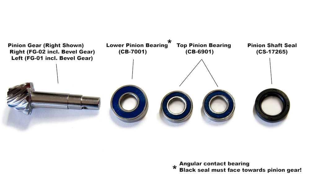
30 Dropout Disassembly Remove drive insert bearing from inside of dropout. Bearing is a slip fit so only light pressure from screw driver is required to remove. Tap down on pinion gear with plastic face hammer. After pinion is removed, slide the bottom bearing out of dropout bore. If bearing stays on pinion shaft, remove by hand or with split bearing puller. Note: lower pinion bearing is angular contact so if pressure is applied in the wrong direction it may come apart. If bearing comes apart, it must be replaced. Remove top driveshaft seal from dropout using small flat blade screwdriver. Be careful not to scratch inner bore. Remove top pinion bearings from upper bore by tapping them lightly tapping from inside the dropout with non-marring punch. Pry axle o-ring from dropout using small pick. Page 29


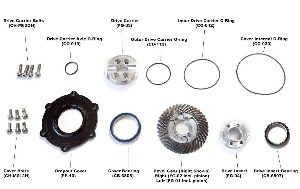
31 Dropout Disassembly Remove 4 drive carrier bolts with 4mm Allen wrench. The inner hardened bevel gear can be clamped with soft jaws in a vise or the drive carrier can be held with square bar stock to keep the assembly from moving as you unscrew the bolts. Lightly tap the outside face of drive carrier with plastic hammer to break it free from gear and drive insert. Remove axle o-ring from drive carrier with pick. Remove cover o-rings and drive carrier o-ring. Page 30


32 Dropout Disassembly Remove cover bearing with bearing removal punch. Note o-ring lip near inner race of bearing is easily damaged. Only apply pressure to inner race of bearing. Remove drive insert from gear with hammer and bearing removal tool. Before reassembly of dropouts, all parts must be cleaned and inspected individually for damage or wear. Parts can be cleaned with solution no different then OEM fork. Be sure to blow dry dropouts and parts prior to reassembly if cleaning solution is used. Pinion and bevel gear must be replaced as a set. If bearings are seized or hard to turn by hand they must be replaced or cleaned and repacked with grease. Be sure to grease all o-rings and gears during reassembly. Page 31


33 Dropout Assembly Drive cover bearing into cover with bearing installation tools and install inner and outer cover 0-rings. Note: all 0-rings should be lightly coated with grease before being reassembled. Insert drive carrier o-ring on drive carrier and insert drive carrier into cover and tap into place. Note: face of drive carrier should be flush with cover bearing and machined cover surface. Place drive insert on tooth side of bevel gear and line up all four threaded holes with clearance holes on gear. Set cover and drive carrier on top of bevel gear assembly, with smooth side of gear facing the cover. Line up 4 bolt holes and thread drive carrier bolts into drive insert. Blue Loctite should be used on bolts. Final tightening of bolts will require a square bar or soft jaws to keep gear from spinning. Torque bolts to 8ft ft-lbs. Check that bevel gear spins freely on cover. If it does not spin freely, check to make sure all o-rings and the cover bearing are properly seated. If new o-rings are used, there may be more friction until o-rings seat and break in. Insert axle o-ring into drive carrier. Page 32


34 Dropout Assembly Warning: Bevel gears are right and left hand specific and must be installed in the correct dropout or damage to the system can occur. The Left Bevel Gear Set shown below must go in the disk side dropout. Note the difference in the spiral direction on each gear set. Note: Be sure dropout is clean before proceeding Insert top pinion bearings and seal into driveshaft bore at top of dropout using bearing driver. Note, be careful not to damage seal or nick chrome fork plating with hammer. Use plastic faced hammer. Apply light grease to pinion seal Insert bottom pinion bearing onto pinion gear. WARNING: black seal must be facing down towards gear teeth. If bearing is not inserted correctly, severe damage can occur! Slide bearing and pinion gear into bore. Make sure bearing is fully seated. Page 33


35 Dropout Assembly If needed use hammer and soft punch to tap end of pinion gear to seat bearing. Insert axle o-ring into dropout. Install drive insert bearing and wedge small flat blade screwdriver in between pinion gear and inner bearing to keep pinion gear in place when the splined shaft is installed. Slide splined driveshaft onto pinion gear, making sure to line up the set screw holes. Lightly tap end of spline shaft with plastic faced hammer to slide it down onto pinion gear and line up set screw holes. Page 34


36 Dropout Assembly Insert set screw with light dab of blue Loctite. When set screw is fully seated, it will be slightly below the surface of driveshaft. If not, make sure that spline shaft is fully seated on pinion gear. Grease pinion gear and bevel gear with Shell Lithium grease. Insert cover/bevel gear assembly onto dropout. Insert 6 cover bolts and tighten in a cross star pattern using a 4mm Allen wrench. Tighten to 8ft-lbs. Check that drive carrier spins freely and wipe excess grease from outside of dropout. Reinsert bellow and bellow clamp over spline shaft and crimp bellow down using crimping tool or vise grips. WARNING: The band of clamp must be over the set screw to ensure that the set screw can not back out. Lightly grease spline shaft with Shell Lithium grease. Reinsert forks into triple clamps. Page 35

37 Fork Spline Bearing Service Page 36
.")
38 Fork Spline Bearing Service Cut Safety wire from boot and slide it off the housing. Remove forks from triple clamps (see page 25). Slide housing assembly off of linear driveshaft. Page 37


39 Fork Spline Bearing Service Unscrew grease port from linear bearing housing. Slide housing sleeve off of housing. Remove linear bearing retaining ring. Page 38


40 Fork Spline Bearing Service Slide linear bearing out of housing and inspect. If ball bearings inside of the case are corroded or worn, replace linear bearing. Warning: Do not use hammer and punch to remove bearing as it may damage the bearing. If bearing will not slide out apply pressure to the bearing lip with an 8mm nut driver to remove it. If shaft seal is damaged or worn, pry it out and replace it with a new seal. Remove felt from housing sleeve and inspect. If needed, replace felt. Note: Dirt will pack up in felt. The felt can be cleaned and reused. Page 39


41 Fork Spline Bearing Service Saturate felt with gear oil and place it back in housing sleeve. Reassembly of linear bearing housing is the reverse of disassembly. Warning: Use red Loctite on grease fitting or it may back out and cause the housing sleeve to slide down while riding. Warning: When sliding linear bearing housing back unto driveshaft, carefully align the ball bearings with the grooves in the driveshaft. Do not force the housing onto the driveshaft. Groove should be approximately 90 degrees to the grease fitting. Page 40


42 Boot Replacement Note: To remove and replace the drive shaft boots, it is not necessary to remove the forks. The service can be done by removing the fork guards and following the instructions below. Remove Fork Guard Remove Boot Clip with wire cutters Pull up boot and loosen Drive shaft set screw Insert screw drive in vent holes and tap screwdriver. Page 41


43 Boot Replacement The shaft will slide upwards Remove Old boot and replace with a new boot. Be sure to add the clip on the bottom of the shaft Reinstall the drive shaft and tighten set screw Slide boot back over the bottom shaft and set screw. Crimp the clamp around the boot and set screw and reinstall the fork guard Page 42


44 Triple Clamp Removal Note: To service the triple clamp chains, sprockets and bearings it is recommended that you leave the bottom triple clamp attached to the bike. This will make it easier to pull the cover off. For servicing the steerer tube bearings, or replacing the head tube gears, the triple clamps will need to be removed. Remove forks and front fender from triple clamps. Loosen the two preload bar pinch bolts. Remove the preload bolts with a 22mm Wrench. With a plastic faced hammer, tap the bottom triple clamp to unseat it from the frame. Page 43


45 Triple Clamp Removal Slide the bottom triple clamp out of the frame. Pull the top triple clamp assembly out of the frame. Note: It may be necessary to tap the underside of the top triple clamp with a plastic faced hammer to unseat it from the frame. Page 44

46 Triple Clamp Service Page 45
47 Triple Clamp Service Page 46


48 Bottom Triple Clamp Disassembly Note: To service the triple clamp chains, sprockets and bearings it is recommended that you leave the bottom triple clamp attached to the bike. This will make it easier to pull the cover off. For servicing the steerer tube bearings, or replacing the head tube gears, the triple clamps will need to be removed. For picture clarity, the triple clamp was removed from the bike. Remove the forks and spline bearing assembly. Remove the 4 cover bolts from the bottom of the triple clamp with a 6mm Allen wrench. Carefully pull on the shaft sprockets and ease the cover down from the bottom triple clamp. The Left shaft will pull down with the cover. The right shaft will stay in place and the cover will slide down over it. Page 47


49 Bottom Triple Clamp Disassembly Remove the right shaft sprocket and the chain inside of triple clamp cavity. Pull center bottom sprocket off of the cover and remove the chain. Pull both shaft sprockets out of cover. Be careful of seal as it slides over snap ring grooves as it can tear the seal. Page 48


50 Bottom Triple Clamp Disassembly Remove cover bearings from cover with bearing puller if they need to be replaced. Remove cover seals and inspect. Replace if needed. Page 49


51 Bottom Triple Clamp Disassembly Remove sprocket snap ring. Remove sprocket and gear by tapping the gear through the sprocket with a plastic faced hammer and pulling it out the top of the steerer tube. Remove gear from steerer tube. If bearing comes out with gear, remove bearing from gear with split bearing puller if it does not slide off easily. If top bearing remains in steerer use a punch to remove it. Page 50


52 Bottom Triple Clamp Disassembly Tap the bottom output bearing from the bottom steerer tube. Inspect gears and bearing and replace any parts if needed. Note: Head tube gears must be replaced in sets. Page 51


53 Warning: Replacing the taper bearing is a job for your dealer. Do not attempt to do this on your own. Bottom Taper Bearing Removal Remove the preload bars from the bottom triple clamp. Press the steerer tube out of the bottom triple clamp with an arbor or hydraulic press. The steering stops should be supporting the triple clamp as the steerer is pressed out. Press the taper bearing and seal off of steerer tube with an aluminum sleeve available from Christini. Press new taper bearing and seal onto steerer tube. Coat mating surface of triple clamp and steerer tube with green Loctite. Press steer tube into triple clamp. Page 52


54 Bottom Triple Clamp Assembly Press steerer bearing into the top of the steerer tube. Press steerer bearing into bottom of the steerer tube. Install bottom output gear and tap sprocket back onto bottom of gear using a plastic faced hammer. Sprocket is fully seated when the end of it is flush with the snap ring groove. Replace snap ring. Page 53


55 Bottom Triple Clamp Assembly Install cover seals. Press cover bearings back into outer bores of cover. Insert Teflon chain guides into cover if they were removed. Note the wear pattern and be sure that the guides are placed on the same side as they were removed from. Page 54


56 Bottom Triple Clamp Assembly Insert triple clamp bearing onto top of the right shaft sprocket. It will be a slip fit. Wrap chain around top center sprocket and right shaft sprocket. insert shaft sprocket and bearing into bearing bore on triple clamp. It will be a slip fit. Insert triple clamp bearing onto bottom center sprocket. Push left shaft sprocket through cover. Wrap the chain around the left shaft sprocket and bottom center sprocket. Insert bottom center sprocket with bearing into the center cover hole. If needed, grease chains with Shell grease. Slide cover and left shaft sprocket up into bottom triple clamp until the cover meets flush the lip of the bottom triple clamp. If needed use a small screwdriver or pick to push the right chain away from the Teflon block as the cover slides into place. Hint: once the cover makes contact with the bottom triple clamp, rotate the shaft sprockets as you are pushing the cover into its final position. This helps to line everything up correctly. Warning: Left and right shaft sprockets must be installed on the correct side or severe damage to the AWD system can occur. A simple rule to remember is that the lower shaft sprocket goes on the rider s left side (ie: Left=Low). Page 55

57 When cover is in place screw down the cover bolts with a 6mm Allen wrench. Note: Use blue Loctite on cover bolts. Torque bolts to 12 ft-lbs Bottom Triple Clamp Assembly Page 56

58 Top Triple Clamp Disassembly Pull top output gear and bearing out of top steerer. If bearing does not come out with gear, use blindside bearing puller to remove the bearing If bearing is seized or hard to turn by hand, it should be replaced. Inspect output gear for wear. If it needs to be replaced, all gears in the head tube must be replaced at the same time. Page 57


59 Warning: Replacing the taper bearing is a job for your dealer. Do not attempt to do this on your own. Top Taper Bearing Removal Loosen steerer set screw in triple clamp and remove the steerer tube. Press taper bearing and seal off of steerer tube with an arbor or hydraulic press. Note: A new seal will be needed as it will be damaged when the taper bearing is pressed off the steerer. Press new taper bearing and seal onto steerer tube. Insert steerer tube into top triple clamp and tighten set screw to secure steerer tube. Page 58
60 Top Triple Clamp Assembly Slide the steerer tube bearing back onto the output gear. Press gear and bearing into top steerer tube. Page 59


61 Main Drive Shaft Service Remove the head tube cover from the front of the head tube. Slide the input head tube gear and main driveshaft out the head tube access port. The driveshaft will need to slide out of the clutch hub. If the 3 input bearings do not come out with the input gear, gently tap them out with a punch. Make sure they do not get cocked as they are being tapped out. Warning: If any of the head tube gears are damaged and need to be replaced, all of the head tube gears must be replaced together as a set. Page 60
62 Headset Bearing Service * Picture above shows a head tube not welded to the frame for reference. Page 61


63 Headset Bearing Service Use a punch and remove the inner B543 bearings. If the taper bearing races are corroded or pitted, remove them with a punch. Clean the headset bearing surfaces with degreaser and apply a few drops of green Loctite. Install the inner B543 bearings using a bearing punch. Install the taper bearing races using a bearing punch. Page 62


64 Main Drive Shaft Service Slide the input bearings onto the head tube gear. Slide the driveshaft partially through the frame and install the clutch hub. Be sure the clutch retaining snap ring is on the driveshaft before sliding the clutch hub onto the driveshaft. Slide the driveshaft the rest of the way through the frame, seating the input bearings and gear in the head tube and the clutch hub with the clutch basket. Use a soft punch and lightly tap the gear to be sure it is fully seated. Move the clutch retaining snap ring into the groove closest to the clutch hub. Page 63


65 Triple Clamp Installation Grease the top and bottom taper bearings with Spectro SPL or equivalent waterproof grease. Grease output gears with Shell grease. Check to make sure input head tube gear and bearings are completely seated in the back of the head tube. Slide top triple clamp assembly into the head tube. Before seating the top triple clamp assembly, make sure the output gear and input gear are beginning to mesh correctly. Note: If the two gears are not meshing, it will not be possible to seat the top triple clamp correctly. Tap the top triple clamp with a plastic faced hammer to seat it completely. Page 64


66 Triple Clamp Installation Slide the bottom triple clamp partway into the head tube as you do the following: Align the preload bars so they begin to slide into the top triple clamp. Make sure the bottom output gear and input gear are meshing correctly. Page 65
 with the steerer driveshaft.")


67 Finally, spin the left side sprocket driveshaft to align the bottom center sprocket (located inside the cavity) with the steerer driveshaft. Once turning the sprocket driveshaft also turns the top output gear, everything is aligned correctly. Triple Clamp Installation Tap the bottom triple clamp with a plastic faced hammer to completely seat it in the frame. Screw the preload bolts down until they are flush with the top triple clamp. Page 66
. Tighten the preload bar pinch bolts.")
68 Triple Clamp Installation Turn the preload bolts evenly until there is no play in the headset (usually 1/2-3/4 of a turn). Tighten the preload bar pinch bolts. Page 67
.")


69 Gear Box Removal Remove sidebar cover, chain and sprocket from frame (see page 9). Remove cable and engagement spline from gearbox (see page 11). Slide clutch retaining snap ring up main drive shaft 6 inches or more. Slide clutch hub assembly up main driveshaft unit it clears the clutch basket. Remove 4 shoulder bolts from sidebar with 4mm Allen wrenc h. With Shoulder bolts removed, slide gearbox out of frame. Page 68
70 Gear Box Disassembly Page 69


71 Gear Box Disassembly Slide clutch basket off output gear. Remove output seals from gear box. Remove output snap ring. Page 70


72 Gear Box Disassembly Slide output gear and bearings out of gearbox. Remove input gear and bearing from gearbox by tapping them out through the access holes in the back of the gearbox. Page 71


73 Gear Box Disassembly Remove output retaining ring. Use split bearing puller to press output bearings partially off of the gear. After the bearings move away from the gear, use press to remove bearings completely. Use same steps to remove input bearing from input gear. Inspect gears and bearings and replace if needed. Carefully press new output bearings onto driven gear and replace retaining ring. Carefully press input bearing onto drive gear and replace engagement spline snap ring if it was removed. Page 72


74 Gearbox Assembly Note: Make sure engagement spline snap ring is install on input gear before it is pressed into the gearbox Press input bearing onto gear and insert gear and bearing into gearbox. An aluminum punch and hammer may be needed to gently tap input bearing and drive gear back into place. Make sure bearing is fully seated at the back of the gearbox. Insert output gear and bearings into gearbox. Make sure gears mesh correctly as you are pushing the output gear into place. Reinstall output snap ring. Grease input and output gears using Shell Lithium grease. Install output seals into gearbox making sure seals are installed markings facing out. Grease lip of seals and push clutch basket back onto output gear. Clean any excess grease off of clutch basket. Page 73


75 Clutch Removal Remove gearbox and clutch basket from frame (see page 68). Slide clutch assembly off of main driveshaft and remove. Page 74

76 Clutch Disassembly Page 75


77 Clutch Disassembly Loosen locknut set screw so it will not interfere with the hub threads. Warning: Failure to remove set screw will damage threads in clutch hub. Remove locknut from clutch hub. Remove spring washers, fiber pads and clutch plates and inspect for wear or damage. Note: If metal plates are not scored or warped, they do not need to be replaced. Simply replace fiber plates during standard rebuilt. Page 76

) Use thread file to clean galled hub threads if needed")

78 Clutch Assembly Reassemble clutch hub noting the order of the plates, fibers and spring washers. Be sure the spring washers are in the correct orientation: )) Use thread file to clean galled hub threads if needed Apply anti seize compound to hub thread and thread locknut onto the hub. Tighten until locknut is approximately flush with the hub. Page 77
79 Clutch Assembly Reinstall clutch on bike. To check clutch settings and adjust as necessary, see page 8) Adjust locknut so set screw hole lines up with the nearest flat section on the hub, and tighten set screw. Warning: Once set screw is tightened, do try to turn locknut as this will damage the hub threads Page 78
80 AWD Troubleshooting Problem Solution Front forks feel sticky Clean and lube fork seals. Check to make sure forks are not twisted in triple clamps. Lube front spline shafts with grease. If this does not help, pull down dust boot and check spline shaft for damage. Disassemble spline and check bearing for corrosion and damage. Front wheel is not pulling Make sure engagement switch is turned on and the engagement spline is functioning properly. Check clutch setting for proper torque using wheel check method. Drive system is pulling to one side Check sprag bearings in hub to make sure neither side is slipping. Make sure that drive shafts are free to spin smoothly. Occasionally mud or other debris can hinder one driveshaft from spinning at the proper rate. Clutch Basket has notches in it. This is normal. As long as the notches don t exceed 3/16, Replacement is not needed. Cannot disengage system With bike in neutral rock it back and forth and use the lever to disengage the system. Engagement cable has too much slack in it. Use barrel adjuster to take slack out of cable. Page 79
81 Warranty CHRISTINI AWD LIMITED WARRANTY This LIMITED WARRANTY is a complete and exclusive statement of CHRISTINI s obligations to the ORIGINAL OWNER of a CHRISTINI AWD Motorcycle Kit. CHRISTINI Technologies warrants: -All Modified frames to be free from defects in material and workmanship for a period of ONE (1) year from the date of purchase for the Original Owner. -All other original CHRISTINI AWD components, including the fork machined parts, front hub, gear box, and the components of the CHRISTINI All Wheel Drive (AWD) system including shafts and drive gears are warranted to be free o f defects in material and workmanship for a period of ONE (1) year from the date of Purchase for the Original Owner. OTHER ORIGINAL COMPONENTS Any components not produced by CHRISTINI, including the front suspension fork internal mechanisms, bear their original manufacturer s own warranty and CHRISTINI reserves the right to direct any warranty request relating to those Other Original Components to said manufacturer s customer service department. THESE WARRANTIES DO NOT COVER: Failures or required services which are not due to a defect in material or factory workmanship. Replacement of expendable maintenance items including, but not limited to: Bearings, including linear bearing Seals and O-Rings AWD Clutch Basket, Plates, and Friction Plates Shaft Bellows AWD Engagement cable and housing Sprockets and Drive Chains Parts or accessories affected or damaged by: Normal wear Finish, including frame, anodized machine parts, and coatings on gears, sprockets and driveshafts Improper maintenance including improper clutch settings Lack of proper maintenance Improper installation Deterioration from exposure to the elements The unauthorized alteration of any part The incorporation or use of unsuitable attachments or parts Unsuitable use in an application for which the part was not designed Neglect Misuse Abuse Vandalism Failures caused by or related to any modification not approved by Christini Technologies, Inc. Page 80
82 Warranty Failures caused by or related to any installation of any parts or kits designed for competition only use Use for the following activities: which will VOID these warranties: Racing Competition Rental LIMITED REMEDY Unless otherwise provided, the sole remedy under the above warranty or any implied warranty is limited to the replacement of defective parts with those of equal or greater value at the sole discretion of CHRISTINI. No cash refunds will be offered under this warranty and you will be responsible for labor costs associated with warranty replacements. IN NO EVENT WILL CHRISTINI AWD BE RESPONSIBLE FOR INCIDENTAL OR CONSEQUENTIAL DAMAGES, WHETHER BASED ON CONTRACT, WARRANTY, NEGLIGENCE, OR STRICT PRODUCTS LIABILITY, INCLUDING, WITH- OUT LIMITATION, PERSONAL INJURY DAMAGES, PROPERTY DAMAGE, OR ECONOMIC LOSSES. Note: In those states that do not allow the exclusion or limitation of incidental or consequential damages, the above limitation or exclusion may not apply to you. EXCLUSIONS The above warranty, or any implied warranty, does not cover normal WEAR AND TEAR, and all warranties are void if the motorcycle is used for other than normal activities, including, but not limited to, the failure to follow the directions for assembly, the instructions, warnings and advice found in the owner's manual or using the motorcycle for commercial activities or in competitive events, including off road racing, motocross racing, stunt riding, ramp jumping or similar activities and training for such activities, or events. This warranty does not cover any damage, failure, or loss caused by accident, misuse, abuse, neglect, improper assembly, improper maintenance, or use of parts or devices not consistent with the original intent for the product sold. CHRISTINI TECHNOLOGIES MAKES NO OTHER WARRANTIES, EITHER EXPRESSED OR IMPLIED. ALL IM- PLIED WARRANTIES, INCLUDING THE WARRANTIES OF MERCHANTABILITY AND FITNESS FOR A PAR- TICULAR PURPOSE, ARE LIMITED, IN DURATION TO THAT OF THE EXPRESS WARRANTIES STATED ABOVE. Some states do not allow limitations on how long an implied warranty lasts so the above limitation may not apply to you. The warranty gives you specific legal rights, and you may also have other rights, which vary from state to state. WHAT YOU SHOULD DO Always wear a helmet while riding. Please remember to always ride safely and in control and within your capabilities and limitations. Even under normal riding, motorcycles can be dangerous due to changing and variable riding condi- tions including know n and unknown hazards. WARRANTY CLAIM PROCEDURE If a part is determined to be defective, return said part to your dealership for verification of a defect. The dealer will verify whether the part is defective. If the part is determined to be defective by the dealer, the part will be replaced and the amount of the replacement part will be charged to the customers credit card until it is returned to Christini for verification. Alternatively, the dealer may opt to send the part in for verification before replacement. Upon receipt of the defective part/parts, Christini will determine if the part is eligible for warranty compensation. If the part is found to be defective, the customer will be credited the full amount of the replacement part. This Warranty applies only to the Original Owner (first retail purchaser from motorcycle dealer, distributor, or direct from Christini) Page 81
83 Warranty Bring your AWD kit or motorcycle along with your purchase receipt or other proof of the date of purchase to the dealer where you purchased the AWD Kit or write to the Warranty Service Department at: CHRISTINI AWD 421 N. 7th Street, Suite 200 Philadelphia, PA Phone: (215) Freight costs and any labor charges for part change overs, assembly, repair, or disassembly are the responsibility of the Original Owner and this Warranty offers no cash refunds. Page 82
84 Notes:
85

86
Service Manual CHRISTINI AWD KTM. Christini Technologies, Inc. Version
 Service Manual CHRISTINI AWD KTM Christini Technologies, Inc. tech@christini.com Version 2011-1.0 Warnings: Do not adjust the choke while the bike is moving! Page 2 Page 3 Table of Contents Table of Contents
Service Manual. Christini Technologies, Inc. 611 N. 2nd St Philadelphia, PA fax Version 1.6.
 Christini Technologies, Inc. 611 N. 2nd St Philadelphia, PA 19123 215.351.9895 215.351.9896 fax info@christini.com Version 1.6 Page 1 Notice: Due to the design of the gears, front and rear international
2. Remove front wheels.
 1 PARTS DIAGRAM 2 Installation Instructions: (PASSENGER SIDE) 1. Place jack under center of RUV front end and lift until front wheels clear the ground. Be careful to support the RUV properly so that it
INSTALLATION GUIDE CRF150R Manual Revision:
 REKLUSE MOTOR SPORTS The z-start Pro Clutch INSTALLATION GUIDE CRF150R 191-810 Manual Revision: 032508 2002 Rekluse Motor Sports Rekluse Motor Sports, Inc. 110 E. 43rd Street Boise, Idaho 83714 208-426-0659
Giant Hydraulic Disc Brake System
 Giant Hydraulic Disc Brake System INSTALLATION INSTRUCTI IMPORTANT NOTICE Contact the place of purchase or Authorized Giant Retailer for information on detail of installation and maintenance. Read this
Compressor Clutch Replacement Procedure
 Clutch Replacement Procedure P-1401-WE 819-0316 Installation Instructions An Altra Industrial Motion Company Warner Replacement Clutches for the following compressors: Denso 6E171 10P15 6P148 6C17 Ford
INSTALLATION MANUAL. TORQ Locker TL GM 14 Bolt Installation Instructions. Made in USA By: Page 1 of 8
 INSTALLATION MANUAL TORQ Locker TL-19035 GM 14 Bolt Installation Instructions Made in USA By: Page 1 of 8 Page 2 of 8 INSTALLATION MANUAL TORQ Locker TL-19035 GM 14 Bolt Installation Instructions By: INTRODUCTION
CALIFORNIA TRIMMER MOWER MAINTENANCE MANUAL
 CALIFORNIA TRIMMER MOWER MAINTENANCE MANUAL 2 Table of Contents Section 1: General Information Page Handle Assembly Instructions 4 Maintenance All Models 6 Oil Change Procedures All Models 9 Height Adjustment
DRIVE AXLE Nissan 240SX DESCRIPTION & OPERATION AXLE RATIO & IDENTIFICATION AXLE SHAFT & BEARING R & I DRIVE SHAFT R & I
 DRIVE AXLE 1990 Nissan 240SX 1990 DRIVE AXLES Rear Axle - R200 240SX, 300ZX DESCRIPTION & OPERATION The axle assembly is a hypoid type gear with integral carrier housing. The pinion bearing preload adjustment
TRANSMISSION 6.7 GENERAL HOME. See Figure The transmission is a five-speed constantmesh type housed in an extension of the crankcase.
 TRANSMISSION 6.7 GENERAL See Figure 6-45. The transmission is a five-speed constantmesh type housed in an extension of the crankcase. Mainshaft Neutral Mainshaft st Gear b06x6x Countershaft 4 Out 5 Countershaft
Dodge SpynTec Hub Conversion Kit
 SpynTec SpynTec Industries Installation Instructions for the Dodge SpynTec Hub Conversion Kit I n d u s t r i e s SpynTec Industries LLC. 11501 South Avenue North Lima, Ohio 4445 1.888.90.AXLE Page 1 Warning
HOME OF PRIMO BELT DRIVES QUALITY & PERFORMANCE SINCE 1973 BRUTE FORCE TM. Belt Drive INSTALLATION INSTRUCTIONS
 HOME OF PRIMO BELT DRIVES QUALITY & PERFORMANCE SINCE 1973 BRUTE FORCE TM Belt Drive INSTALLATION INSTRUCTIONS 3-1/2 WIDE / 14mm BELT FITS 1990-2006 EVO & TWIN CAM SOFTAIL PRIMO BRUTE FORCE TM BELT DRIVE
Service Manual CHRISTINI AWD 300 CHRISTINI AWD 250. Christini Technologies, Inc. Version
 Service Manual CHRISTINI AWD 300 CHRISTINI AWD 250 Christini Technologies, Inc. tech@christini.com Version 2015.1 HOW TO USE THIS MANUAL Read this Manual carefully. You will find it contains all the necessary
DYNATRAC PRODUCTS V5.3
 DYNATRAC PRODUCTS V5.3 2000-2008 Dodge Hub Kit Stage 1 4x4, Front Axle Free Spin Conversion Kit Note: This Kit is not Approved for 2007 & up 3500 Cab and Chassis Trucks Due to a Larger U-Joint (If U-Joint
Yukon Gear & Axle. D30, D44 & GM 8.5" Hardcore Locking Hub Installation Guide PLEASE READ COMPLETELY BEFORE INSTALLATION
 Yukon Gear & Axle D30, D44 & GM 8.5" Hardcore Locking Hub Installation Guide PLEASE READ COMPLETELY BEFORE INSTALLATION COPYRIGHT 2014 - Yukon Gear & Axle Application Guide: YHC70005 D30 & D44 30spl -
Transmission Overhaul Procedures-Bench Service
 How to Assemble the Lower Reverse Idler Gear Assembly Special Instructions In 1996 Eaton changed the reverse idler system design. In the nut design, the reverse idler bearing was lubricated through a hole
AT Clutch Major Service Sizes 25, 55, 115
 P-1404 819-0324 AT Clutch Major Service Sizes 25, 55, 115 Installation Instructions Contents Introduction............................ 2 Warranty....................... back cover Failure to follow these
Performance Brake Caliper Guide Bushing Set Installation Guide
 Performance Brake Caliper Guide Bushing Set Installation Guide Proper service and repair procedures are vital to the safe, reliable operation of all motor vehicles as well as the personal safety of those
Yukon Gear & Axle D60 Hardcore Locking Hub Installation Guide
 Yukon Gear & Axle Installation Guide PLEASE READ COMPLETELY BEFORE INSTALLATION Application Guide: YHC70001 D60 35spl - 79-93 Dodge internal flange design - 79-91 GM - 78-97 Ford YHC70002 D60 35spl - 99-04
WARRANTY INFORMATION AMERICAN MADE MANITOU SUSPENSION
 AMERICAN MADE MANITOU SUSPENSION CONGRATULATIONS ON CHOOSING THE LATEST IN SUSPENSION TECHNOLOGY AVAILABLE, A 2003 MANITOU DORADO FORK BUILT IN THE USA. This DORADO fork is fully assembled and is ready
4. Remove the cotter pin that secures the castle nut to the axle. Once you have done this remove the castle nut and pull off the hub/rotor assembly.
 780 Professional Drive N. Shreveport, LA 71105 Phone (318)-524-2270 Fax (318)-524-2297 Max Clearance Honda Pioneer 1000 Front Forward Arched Control Arm Kit Read before Installation This product is designed
TRANSMISSION 6.7 GENERAL HOME. See Figure The transmission is a five-speed constantmesh type housed in an extension of the crankcase.
 TRANSMISSION 6.7 GENERAL See Figure 6-46. The transmission is a five-speed constantmesh type housed in an extension of the crankcase. b06x6x Neutral st Gear Mainshaft Mainshaft 4 5 4 5 Countershaft Out
Compressor Clutch Replacement Procedure
 P-1411 819-0361 Compressor Clutch Replacement Procedure Installation Instructions World Clutch with Unidamp Armature for Ford FX-15 and FS-10 Compressors and all Denso Models with 30mm bearing fit. Keep
Installation Manual TWM Performance Short Shifter Cobalt SS/SC, SS/TC, HHR SS, Ion Redline and Saab 9-3
 Page 1 Installation Manual TWM Performance Short Shifter Cobalt SS/SC, SS/TC, HHR SS, Ion Redline and Saab 9-3 Please Note: It is preferable to park on a flat surface, as you will have to engage and disengage
INSTALLATION INSTRUCTIONS FOR THE MOTOR TRIKE CROSS COUNTRY / CROSS ROADS / HARD BALL RAKE KIT
 INSTALLATION INSTRUCTIONS FOR THE MOTOR TRIKE CROSS COUNTRY / CROSS ROADS / HARD BALL RAKE KIT Thank you for choosing the Motor Trike Cross Country / Cross Roads / Hard Ball rake kit. We ask that you read
V PN 4-155N1-K (N1 Shift Drum Kit For Ratchet Style Top Covers) PAGE 1 COVER
 PAGE 1 COVER") BAKER 4-SPEED CRUISE N1 DRIVE SHIFT TOP DRUM COVER KIT V3-05222014 PN 4-155N1-K (N1 Shift Drum Kit For Ratchet Style Top Covers) PAGE 1 COVER FEATURES Tired of stalling your jockey shift bike while trying
BAKER 4-SPEED CRUISE N1 DRIVE SHIFT TOP DRUM COVER KIT V3-05222014 PN 4-155N1-K (N1 Shift Drum Kit For Ratchet Style Top Covers) PAGE 1 COVER FEATURES Tired of stalling your jockey shift bike while trying
INSTALLATION GUIDE. Kawasaki KLR Manual Revision:
 REKLUSE MOTOR SPORTS The z-start Pro Clutch INSTALLATION GUIDE Kawasaki KLR650 191-640 Manual Revision: 030308 2007 Rekluse Motor Sports Rekluse Motor Sports, Inc. 110 E. 43rd Street Boise, Idaho 83714
PRO-CLUTCH TM PC-1100-CA Evo Big-Twin. chain drive primary PC-1200-CA Evo Big-Twin. chain drive primary PC-1298-CA
 HOME OF PRIMO BELT DRIVES PRO-CLUTCH TM PC-1100-CA / PC-1200-CA / PC-1298-CA / 1056-0020 INSTALLATION INSTRUCTIONS PC-1100-CA 1986-1989 Evo Big-Twin chain drive primary Pro-Clutch TM Stock Clutch PC-1200-CA
Maintenance Information
 80234313 Edition 1 June 2006 Air Grinder, Die Grinder, Sander and Belt Sander Series G1 (Angle) Maintenance Information Save These Instructions WARNING Always wear eye protection when operating or performing
Mustang Differential Gears - Installation Instructions
 Mustang Differential Gears - Installation Instructions The below installation instructions work for the following products: Ford Racing Gears - 3.73 Gears for 8.8" Ford Rear End Ford Racing Gears - FRPP
White Industries ENO Eccentric Rear Hub Instructions
 White Industries ENO Eccentric Rear Hub Instructions Tools required: 4mm allen/hex wrench, 19mm open end wrench, 9mm open end wrench or bench vise, ENO Eccentric Axle Tool or 10mm socket, bearing puller
Installation Manual TWM Performance Kia Forte Short Shifter
 Installation Manual TWM Performance Kia Forte 2009+ Short Shifter Begin the installation by parking on a flat surface, as you will have to engage and disengage the hand brake and shift from gears to neutral.
INSTALLATION. DRIVING LIGHTS for FLHT/FLHX/FLHR 5005
 DRIVING LIGHTS for FLHT/FLHX/FLHR 5005 PARTS INCLUDED 1 Right Driving Light Assembly 1 Left Driving Light Assembly 1 Right Driving Light Bracket 1 Left Driving Light Bracket 4 Driving Light Bracket Plugs
DISASSEMBLY AND ASSEMBLY
 205-03-1 Front Drive Axle/Differential Ford 8.8-Inch Ring Gear 205-03-1 DISASSEMBLY AND ASSEMBLY Axle Front Drive Special Tool(s) 2-Jaw Puller 205-D072 (D97L-4221-A) Special Tool(s) Carrier Bearing Replacer
INSTALLATION GUIDE. Clutch Cable Actuated Models Manual Revision:
 REKLUSE MOTOR SPORTS The z-start Pro Clutch INSTALLATION GUIDE Clutch Cable Actuated Models 191-800 Manual Revision: 061810 2002 Rekluse Motor Sports Rekluse Motor Sports, Inc. 110 E. 43rd Street Boise,
WARNING!!! READ AND UNDERSTAND ALL INSTRUCTIONS BEFORE PROCEEDING. MAKE SURE THAT YOU HAVE ALL TOOLS AND PARTS BEFORE BEGINNING THE INSTALLATION.
 INSTALLATION INSTRUCTIONS FOR 2008-09 JEEP LIBERTY & 2007-09 Dodge Nitro 2" SUSPENSION LIFT KIT PART NUMBER 582 WARNING!!! READ AND UNDERSTAND ALL INSTRUCTIONS BEFORE PROCEEDING. MAKE SURE THAT YOU HAVE
DRIVE AXLE Volvo 960 DESCRIPTION & OPERATION AXLE IDENTIFICATION DRIVE AXLES Volvo Differentials & Axle Shafts
 DRIVE AXLE 1994 Volvo 960 1994 DRIVE AXLES Volvo Differentials & Axle Shafts 960 DESCRIPTION & OPERATION All 960 station wagon models use type 1041 rear axle assembly. All 960 4-door models use type 1045
Next, set the bar level and tighten it down. Do this on both the driver and passenger sides.
 Next, set the bar level and tighten it down. Do this on both the driver and passenger sides. Using two tape measures, measure the outside width at the front and the rear of the tubes. The front dimension
Maintenance Information
 04581245 Edition 2 May 2014 Air Grinder, Die Grinder and Sander Series G2 (Angle) Maintenance Information Save These Instructions Product Safety Information WARNING Failure to observe the following warnings,
INSTALLATION INSTRUCTIONS FOR THE MOTOR TRIKE GL1500 RAKE KIT
 INSTALLATION INSTRUCTIONS FOR THE MOTOR TRIKE GL1500 RAKE KIT Thank you for choosing the Motor Trike GL1500 Rake Kit. We ask that you read the directions before you start and follow them very closely.
Maintenance Instructions
 General Note These instructions contain information common to more than one model of Bevel Gear Drive. To simplify reading, similar models have been grouped as follows: GROUP 1 Models 11, 0, 1,, (illustrated),,
$1.00 FOR THE TQIO/RCIO
 $1.00 FOR THE TQIO/RCIO m mm HDBBYSHOP Champion Jay Halsey has an impressive track record. One of Jay's advantages is a whisper smooth tranny thanks to his dad, Jim. Now you can build a Halsey transmission!
PROPELLER SHAFT & DIFFERENTIAL CARRIER SECTIONPD CONTENTS
 PROPELLER SHAFT & DIFFERENTIAL CARRIER SECTIONPD CONTENTS PREPARATION...2 PROPELLER SHAFT...5 On-Vehicle Service...6 Removal and Installation...7 Inspection...7 Disassembly...7 Assembly...8 ON-VEHICLE
1999 F-150/250 Workshop Manual
 Page 1 of 30 SECTION 205-03: Front Drive Axle/Differential Ford 8.8-Inch Ring Gear 1999 F-150/250 Workshop Manual DISASSEMBLY AND ASSEMBLY Procedure revision date: 01/08/2003 Axle Front Drive Special Tool(s)
First, check and record the camber and caster readings, they will be adjusted later.
 First, check and record the camber and caster readings, they will be adjusted later. The caliper-mounting bosses are machined perpendicular to the spindle so they are an excellent place for the level.
Maintenance Information
 80234313 Edition 2 May 2014 Air Grinder, Die Grinder, Sander and Belt Sander Series G1 (Angle) Maintenance Information Save These Instructions Product Safety Information WARNING Failure to observe the
INSTALLATION GUIDE. Clutch Cable Actuated Models Manual Revision:
 REKLUSE MOTOR SPORTS The z-start Pro Clutch INSTALLATION GUIDE Clutch Cable Actuated Models 191-800 Manual Revision: 041513 2012 Rekluse Motor Sports Rekluse Motor Sports, Inc. 12000 W Franklin Rd. Boise,
Gen 2 Clutch/Brake UniModule UM-50, UM-100, UM-180
 Gen 2 Clutch/Brake UniModule UM-50, UM-100, UM-180 P-273-4 819-0528 Installation Instructions Vented Enclosed Version Optional An Altra Industrial Motion Company Contents Mounting to a C-Face Motor........3
I N S TA L L AT I O N
 I N S TA L L AT I O N 5008 fits: H-D: '80-Up Electra glide, tour glide, road king, road glide or street glide PartS Included 1 Right Fork Mount Assembly 1 Left Fork Mount Assembly 2 H3 Driving Light Assemblies
Installation Instructions
 Preparing your vehicle to install your brake system upgrade 1. Rack the vehicle. 2. If you don t have a rack, then you must take extra safety precautions. 3. Choose a firmly packed and level ground to
Fluid-O-Tech ROTOFLOW ROTARY VANE PUMP REBUILD MANUAL
 Fluid-O-Tech PUMP TECHNOLOGY AT ITS BEST WWW.FLUID-O-TECH.COM Office: 161 Atwater St., Plantsville, CT 06479 Phone: (860) 276-9270 Fax: (860) 620-0193 ROTOFLOW ROTARY VANE PUMP REBUILD MANUAL 08/09 Ed.,
FRONT WHEEL AND BRAKE DISCS. Order Job/Part Q ty Remarks Removing the front wheel and brake discs NOTE:
 FRONT WHEEL AND BRAKE DISCS EAS00514 SIS FRONT WHEEL AND BRAKE DISCS 1 2 3 4 Order Job/Part Q ty Remarks Removing the front wheel and brake discs Remove the parts in the order listed. Place the motorcycle
WARNING!!! READ AND UNDERSTAND ALL INSTRUCTIONS BEFORE PROCEEDING. MAKE SURE THAT YOU HAVE ALL TOOLS AND PARTS BEFORE BEGINNING THE INSTALLATION.
 INSTALLATION INSTRUCTIONS FOR 2008 JEEP LIBERTY & 2007-08 Dodge Nitro 2" SUSPENSION LIFT KIT PART NUMBER 582 WARNING!!! READ AND UNDERSTAND ALL INSTRUCTIONS BEFORE PROCEEDING. MAKE SURE THAT YOU HAVE ALL
354 CHAPTER EIGHT WATER PUMP
 354 CHAPTER EIGHT 33 Shift handle F : Forward N : Neutral R : Reverse proper alignment of the water tube to the water pump opening during each installation attempt. Make sure the locating pins enter the
LIMITED SLIP DIFFERENTIAL INSTALLATION
 Installation of the limited slip gear can be done with axle out of car or with car lifted to gain access from underneath. Refer to repair manual for proper lifting instructions if car is to be lifted.
1984 Dodge W250 PICKUP
 1984 Dodge W250 PICKUP Submodel: Engine Type: V8 Liters: 5.2 Fuel Delivery: CARB Fuel: GAS Dana 44 MODELS THROUGH 1984 2. Raise and safely support the vehicle, then remove the wheel hub and bearings as
Next, chase the threads in the lower A-arm mounts with the 5/8-18 tap and blowout any remaining particles.
 Next, chase the threads in the lower A-arm mounts with the 5/8-18 tap and blowout any remaining particles. Now, apply some anti-seize to the threads of the pivot stud. Also put anti-seize inside the bore
Rear End Installation and Bearing Kit - 8.8in (86-12 V8; V6)
") Rear End Installation and Bearing Kit - 8.8in (86-12 V8; 11-13 V6) Tools Required: Jack Stands 5 Floor Jack 2 Oil Pans 1 Wheel Blocks 2 Differential Oil 3 qts Friction Modifier 3 bottles Tube of Black
Rear End Installation and Bearing Kit - 8.8in (86-12 V8; 11-13 V6) Tools Required: Jack Stands 5 Floor Jack 2 Oil Pans 1 Wheel Blocks 2 Differential Oil 3 qts Friction Modifier 3 bottles Tube of Black
Ford 9 XD Aussie-Locker Install Instructions.
 Ford 9 XD-45831 Aussie-Locker Install Instructions. Before the install check the following. 1. Must be 31 spline 4-pinion carrier. 2. Must be an open carrier not a limited slip. 3. Refer to Ford or vehicle
STāSIS Engineering R8 Brake System
 STāSIS Engineering R8 Brake System Brake Kit Installation Instruction Application Guide SE811-B30-91-00 R8 Brake System Special Tools Required Qty Description 1 10 MM Allen Head Socket 1 M10 Triple Square
2001 Dodge RAM 3500 PICKUP
 1 of 76 9/14/2012 7:02 PM 2001 Dodge RAM 3500 PICKUP Submodel: Engine Type: L6 Liters: 5.9 Fuel Delivery: FI Fuel: DIESEL Subarticles MANUAL- NV3500 - DISASSEMBLY MANUAL- NV3500 - DISASSEMBLY MANUAL -
Gen 2 Clutch/Brake UniModule UM-50, UM-100, UM-180
 Gen 2 Clutch/Brake UniModule UM-50, UM-100, UM-180 P-273-4-WE 819-0528 Service & Installation Instructions Vented Enclosed Version Optional An Altra Industrial Motion Company Contents Mounting to a C-Face
Maintenance Information
 16573370 Edition 2 February 2014 Air Grinder 99V Series Maintenance Information Save These Instructions Product Safety Information WARNING Failure to observe the following warnings, and to avoid these
Please contact BrakeAway Products tech support for additional (503) or
 or") Congratulations on the purchase of your new BrakeAway Motorcycle Cruise Control. At BrakeAway Products, we are committed to your complete satisfaction. With proper installation, use, and periodic maintenance,
Congratulations on the purchase of your new BrakeAway Motorcycle Cruise Control. At BrakeAway Products, we are committed to your complete satisfaction. With proper installation, use, and periodic maintenance,
TSS Fit Kit Installation Instructions Timbersled Snow Bike System
 TSS Fit Kit Installation Instructions Timbersled Snow Bike System Information needed before you start: Read the entire installation instructions before starting. The instruction sheet is universal for
12 L * OH**
 Parts Manual Ersatzteil--Liste 12L27.. series 0.9 hp ERGO Short Coupled Low Profile Grinders & Sanders 45--8175 TOOL CLASSIFICATION 12 = ERGO Grinder/Sander 12 L 2 7 12 27 08* OH** -- TYPICAL MODEL THROTTLE
INSTALLATION. Note: Not all parts will be used in the installation of this product. -cont.-
 5005 Fits: 06-up FLHX, 04-up Screamin Eagle Ultra Classic Electra Glide & Screamin Eagle Electra Glide Classic, '97-up FLHT, FLHTC, FLHTCU, FLHR PartS Included 1 Right Driving Light Assembly 1 Left Driving
INSTALLATION INSTRUCTIONS FOR FORD 4WD SUPER DUTY 6 SUSPENSION SYSTEM
 INSTALLATION INSTRUCTIONS FOR 1999-2004 FORD 4WD SUPER DUTY 6 SUSPENSION SYSTEM Requires the following parts for a complete installation: Front Leaf Springs P/N 60SD6 Hardware Kit P/N 6000H Vehicle specific
BAG 3 (2) 2.25 x 1 Sleeves (4) 1/4 Nylock Nuts (4) 1/4 x 2 Bolts (4) 3/8 Nylock Nuts (4) 3/8 Flat Washers (2) 3/8 U-Bolts
 2.25 x 1 Sleeves (4) 1/4 Nylock Nuts (4) 1/4 x 2 Bolts (4) 3/8 Nylock Nuts (4) 3/8 Flat Washers (2) 3/8 U-Bolts") INSTALLATION INSTRUCTIONS PART # DESCRIPTION 799 Lincoln Ave. Riverside, CA 90 Phone: 9.689.ICON Fax: 9.689.06 90 00+ RAPTOR REAR BUMPSTOP SYSTEM ** READ ALL INSTRUCTIONS THOROUGHLY FROM START TO FINISH
INSTALLATION INSTRUCTIONS PART # DESCRIPTION 799 Lincoln Ave. Riverside, CA 90 Phone: 9.689.ICON Fax: 9.689.06 90 00+ RAPTOR REAR BUMPSTOP SYSTEM ** READ ALL INSTRUCTIONS THOROUGHLY FROM START TO FINISH
Installation manual. 4.5 suspension system June 2007 Dodge Ram 2500 / Part # Part # Important customer information:
 Installation manual 4.5 suspension system 2003 - June 2007 Dodge Ram 2500 / 3500 Part # 34003 sj11407rev.03 Part # 34003 2003 - June 2007 Dodge Ram 2500 / 3500 4.5 suspension system Part # Description
TH400 STREETFIGHTER SERIES VALVE BODY MANUAL/AUTO VALVE BODY INSTALLATION INSTRUCTIONS
 1 INSTRUCTIONS TH400 STREETFIGHTER SERIES VALVE BODY 1965-87 MANUAL/AUTO VALVE BODY INSTALLATION INSTRUCTIONS TCI 222400 TCI 222400 ALLOWS AUTOMATIC SHIFT FEATURES IN THE DRIVE POSITION Thank you for choosing
Installation manual. 3 suspension system Toyota Tacoma. 4x4 and 2WD PreRunner. Part # Part # Important customer information:
 Installation manual 3 suspension system 2005 2018 Toyota Tacoma 4x4 and 2WD PreRunner Part # 52907 sj11112011rev.05 Part # 52907 2005-2018 Toyota Tacoma 4x4 and 2WD PreRunner 3 suspension system Part #
 .1..2..3..4..5..6..7..8..9..10. MANITOU SUSPENSION FORKS CONGRATULATIONS ON CHOOSING A 2003 MANITOU SIX FORK. This Manitou SIX fork is fully assembled and ready to be installed onto your bicycle. It comes
Warning Statement Read Before Riding
 Table of Contents Technical Information-----------------------------------1 Warning Statement--------------------------------------2 Read Before Riding------------------------------------- List Of Parts-----------------------------------------------4
KING KONG CLUTCH INSTALLATION INSTRUCTIONS
 KING KONG CLUTCH INSTALLATION INSTRUCTIONS over view BAKER KING KONG CLUTCH V.05_091008 FEATURES: 1 Piece steel clutch basket design 66 tooth ring gear configuration, 23% thicker than stock 20 massive
Installation manual. 3.5 suspension system Chevy / GMC 2500HD / 3500HD With contact overloads Part # 13090
 Part # 13090 2011-2016 Chevy / GMC 2500HD / 3500HD With contact overloads 3.5 suspension system Part # Description Qty. 13085-01 DS & PS Upper control arm 2 13085-02 DS & PS Front upper shock bracket 2
Installation Manual. Uniball Upper Control Arm Kit Toyota Tacoma 4x Toyota 4Runner 4x Toyota Tundra 4x4 Part # 50965
 Part # 50965 Uniball upper control arm kit Part # Description Qty. 50965-01 Driver side upper control arm 1 50965-02 Passenger side upper control arm 1 50965-03 Driver side knuckle support bracket 1 50965-04
Installation manual. 2 Suspension System. Ford F150 4WD and 2WD. Part # Part # Ford F150 4WD and 2WD
 Installation manual 2 Suspension System 2009-2018 Ford F150 4WD and 2WD Part # 22929 sj12112013rev.03 Part # 22929 2009-2018 Ford F150 4WD and 2WD 2 Suspension System Part # Description Qty. 22909-01 Front
Installation manual Toyota Tundra 4WD & 2WD - 2 front leveling kit Toyota Sequoia 4WD & 2WD - 2 front leveling kit Part # 52070
 Part # 52070 2007-2016 Toyota Tundra 4WD & 2WD 2008-2011 Toyota Sequoia 4WD & 2WD 2 front leveling kit Part # Description Qty. 52070-01 Front strut spacers 2 52070NB Hardware bag 1 52070INST Instruction
LOR Series Trig-O-Matic Lite Overload Release Clutch
 LOR Series Trig-O-Matic Lite Overload Release Clutch P-3029-BG LOR Series Installation and Operation An Altra Industrial Motion Company Contents I. Introduction A. Operating Principle... 3 B. Torque Adjustment...
Installation manual. 4 suspension system Chevy or GMC WD. Part # Part # Important customer information:
 Installation manual 4 suspension system 2014-2018 Chevy or GMC 1500 4WD Part # 14059 sj09052013rev.01 Part # 14059 2014-2018 Chevy or GMC 1500 4WD 4 suspension system Part # Description Qty. 14056-01 Upper
 Page 1 of 5 Section 05-03A: Axle, Front Drive, Dana Models 44 and 50 1996 Bronco/F-Series Workshop Manual REMOVAL AND INSTALLATION Procedure revision date: 06/19/2000 Spindle, RH and LH Shaft and Joint
Assembly Manual. 1/10th Formula 1 Car
 Assembly Manual 1/10th Formula 1 Car Center Pivot Bag 1 3374 - Center Pivot Socket 40194 - Hard Anodized Alum Pivot ball 3254-2-56 *Note - Sometimes it is helpful to slightly over-tighten the top clamp
Installation manual 4 suspension system Toyota Tacoma 4x4 and 2WD PreRunner W/Uni-ball Upper Control arms Part # 54910
 Part # 54910 2005-2018 Toyota Tacoma 4x4 and 2WD PreRunner 4 suspension system W/Uni-ball upper Arms Part # Description Qty. 52907-02 Strut pre-load spacer 2 54910-01 Upper strut spacer 2 54910-02 Driver
BRAKE SYSTEM Toyota Celica DESCRIPTION DRUM BRAKES ADJUSTMENTS BRAKE PEDAL HEIGHT ADJUSTMENTS BRAKE PEDAL FREE PLAY ADJUSTMENTS
 BRAKE SYSTEM 1988 Toyota Celica 1988-89 BRAKES Toyota Celica, Corolla, MR2, Tercel DESCRIPTION The hydraulic brake system uses a tandem master cylinder with a vacuum power assist servo. MR2 and some Celica
CHASSIS CONTENTS FRONT WHEEL 6-1 FRONT BRAKE 6-6 FRONT FORK 6-14 STEERING STEM 6-20 REAR WHEEL AND REAR BRAKE 6-25 SUSPENSION 6-31 REAR SWING ARM 6-36
 CHASSIS CONTENTS FRONT WHEEL 6-1 FRONT BRAKE 6-6 FRONT FORK 6-14 STEERING STEM 6-20 REAR WHEEL AND REAR BRAKE 6-25 SUSPENSION 6-31 REAR SWING ARM 6-36 6 6-1 CHASSIS FRONT WHEEL REMOVAL Support the machine
E31 Repair Procedure Replace Front Wheel Hub/Bearing Assembly
 E31 Repair Procedure 31-21 Replace Front Wheel Hub/Bearing Assembly Disclaimer This repair procedure is provided as is and is not authoritative with respect to any BMW repair operation. Mark F. Fling is
13. DRIVE TRAIN 13-0 DRIVE TRAIN MXU 500
 13 DRIVE TRAIN SERVICE INFORMATION------------------------------------------------ 13-2 TROUBLESHOOTING----------------------------------------------------- 13-2 FRONT DRIVE SHAFT REMOVAL/INSPECTION/ INSTALLATION
INSTALLATION MANUAL 4.5 I.F.S. SUSPENSION CURR. FORD F150 W/4.2 OR 4.6 LITER PART # 24940
 INSTALLATION MANUAL 4.5 I.F.S. SUSPENSION 1997- CURR. FORD F150 W/4.2 OR 4.6 LITER PART # 24940 SJ101402 PART NUMBER : 24940 1997 CURR. FORD F150 W/4.2 OR 4.6 LITER 4.5 SUSPENSION SYSTEM WITH FRONT SPINDLES
Table of Contents. Technical Information Warning Statement
 Table of Contents Technical Information-----------------------------------1 Warning Statement--------------------------------------2 Read Before Riding-------------------------------------3 List of Parts-----------------------------------------------4
Straight-Bore Clutch LSCC-32, 44, 54
 Straight-Bore Clutch LSCC-32, 44, 54 1 In accordance with Nexen s established policy of constant product improvement, the specifications contained in this manual are subject to change without notice. Technical
CHASSIS CONTENTS EXTERIOR PARTS 7-1 FRONT WHEEL 7-2 FRONT BRAKE 7-6 HANDLEBARS 7-13 FRONT FORK 7-15 STEERING 7-23 REAR WHEEL 7-26 REAR BRAKE 7-30
 CHASSIS CONTENTS EXTERIOR PARTS 7- FRONT WHEEL 7-2 FRONT BRAKE 7-6 HANDLEBARS 7-3 FRONT FORK 7-5 STEERING 7-23 REAR WHEEL 7-26 REAR BRAKE 7-30 REAR SHOCK ABSORBER 7-32 SWING ARM 7-33 7 7- CHASSIS EXTERIOR
INSTALLATION. DRIVING LIGHTS for FLHT/FLHX/FLHR BLACK. THANK YOU FOR CHOOSING KϋRYAKYN!
 THANK YOU FOR CHOOSING KϋRYAKYN! PROTECT YOURSELF AND OTHERS FROM POSSIBLE INJURY AND PROPERTY DAMAGE OR LOSS. PAY CLOSE ATTENTION TO ALL INSTRUCTIONS, WARNINGS, CAUTIONS, AND NOTICES REGARDING THE, USE,
Single Post Caliper Brake VC500
 Single Post Caliper Brake VC500 1 In accordance with Nexen s established policy of constant product improvement, the specifications contained in this manual are subject to change without notice. Technical
Stop! Read This Important Information.
 Stop! Read This Important Information. Stop, Do Not Proceed, Read This This door replacement kit is designed for the replacement of doors on a Supertop ONLY! This door will not work on any other style
INSTALLATION GUIDE. KTM 125, 144, Stroke KTM 250, Stroke KTM 250 SXF, XC, XC-W KTM 450, 505 SXF Manual Revision:
 REKLUSE MOTOR SPORTS The z-start Pro Clutch INSTALLATION GUIDE KTM 125, 144, 200 2-Stroke KTM 250, 300 2-Stroke KTM 250 SXF, XC, XC-W KTM 450, 505 SXF 191-836 Manual Revision: 050307 2002 Rekluse Motor
DYNATRAC V6.0. WARNING: Only perform this installation if you are experienced, fully equipped mechanic.
 DYNATRAC V6.0 1999-2004 Ford Super Duty 250/550-4x4, Front Axle, Free Spin Conversion Kit Some of the less common tools, which will be required: 6 point Spanner socket (OTC #7090-A or equivalent) OR 4
Go-ped ESR750 / ESR750EX Rear Brake Installation Instructions
 Go-ped ESR750 / ESR750EX Rear Brake Installation Instructions This kit provides all the parts you need to install a rear brake on your ESR750 or ESR750EX. It will not work on an ESR Sport, or other Go-ped
Installation Instructions COMPETITION/PLUS SHIFTER Ford Mustang MT82 6-Speed Manual Transmission Catalog#
 Installation Instructions COMPETITION/PLUS SHIFTER 2015-2017 Ford Mustang MT82 6-Speed Manual Transmission Catalog# 3916037 Rev. 00 WORK SAFELY! For maximum safety, perform this installation on a clean,
2 Piece Soft Door Installation Instructions
 2 Piece Soft Door Installation Instructions For: Wrangler/TJ (1997-on) Part Number: 51789 Note: Use of this product will eliminate the factory side mirrors and requires the removal of the entry light bulbs.