KING KONG CLUTCH INSTALLATION INSTRUCTIONS
|
|
|
- Clyde Wood
- 6 years ago
- Views:
Transcription


1 KING KONG CLUTCH INSTALLATION INSTRUCTIONS
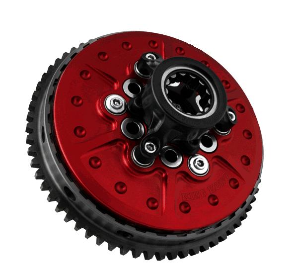
2 over view BAKER KING KONG CLUTCH V.05_ FEATURES: 1 Piece steel clutch basket design 66 tooth ring gear configuration, 23% thicker than stock 20 massive 7" diameter single sided friction plates Red hard anodized carrier and pressure plate Hard anodized inner hub for wear resistance Positive pressure plate alignment accomplished with teflon coated perma glide bushings Coil spring design with 3 different springs included APPLICATION AND REQUIRED HARDWARE: Softail/Dyna Applications (Except 2006 Dyna Motorycles) (94-06 Softails require James Gasket P/N: thicker than stock) FLH Models. (James Gasket (P/N: ) is required- thicker than stock. SKILL LEVEL: As with most things in life there is no substitute for skill and experience. It is highly recommended by BAKER Drivetrain that when performing this task or any task related to the Drivetrain components on your motorcycle, that you refer to your Factory Service Manual for your specific model of bike. SPECIAL TOOLS: 1 3/16 Socket (clutch nut removal) 1 ½ Socket (compensating sprocket nut) Torque wrench 3/16 T-Handle allen Die grinder or cut-off wheel for Big Twin (Except 06 Dyna Motorcycles) ATF (dexron/mercon) fluid PAGE 1 overview
3 baker KING KONG Clutch Installation V.5 table of contents: 1. Overview 2. Table of Contents 3-4. Included Parts Detail 5. Stock Bike Disassembly 6-9. Step by step installation 10. Terms 11. Disclaimer PAGE 2 table of CONTENTS
4 included parts Parts Provided with the BAKER KING KONG Clutch Figure 1. The following parts are included as shown in Figure 1. FIGURE 1. P/N: QTY: Description: /4-20 X 5/8 SHCS /16-20 JAM NUT- GRADE 8 3 9P ADJUSTER SCREW 4 20P107-KK 1 KEY HOLE FITTING /4-28 X 5/8 SHCS 6 20P111-KK 6 SPRING CUP, POLISHED 7 LC-095J-05M 6 SPRING, YELLOW, 240 lbs. 7 LC-105J-05M 6 SPRING, RED, 360 lbs. 7 LC-112J-05M 6 SPRING, BLUE, 480 lbs. 8 PAPZ1004P10 6 PERMA GLIDE BUSHING 9 20P105-KK 1 PRESSURE PLATE INTERNAL SPLINED FRICTION PLATE EXTERNAL SPLINED FRICTION PLATE PAGE 3 PARTS
5 INCLUDED PARTS Parts Provided with the BAKER KING KONG Clutch continued Figure 2. The following parts are included as shown in Figure 2. FIGURE 2. P/N: QTY: Description: /4-20 X 1 3/4 SHCS 12 20P101-KK 1 INNER HUB 13 20P104-KK 1 FLANGE / BACKING PLATE /4-20 X 5/8 SHCS RRRI 1 1 7/16 INTERNAL SNAP RING /2 LEFT HAND THREADED RETAINER 17 20P103-KK 1 FLANGED HUB 18 20P100-KK 1 BASKET, CLUTCH 19 20P102-KK 1 CARRIER, CLUTCH 20 10FS0KFC X 1/2 FSHCS BEARING, INA DOUBLE ROW, CARRIER PP 1 SNAP RING, EXTERNAL, FLANGED HUB SNAP RING, INTERNAL 72MM, CARRIER 24 D4A-35 * SPROCKET, 35 TOOTH 24 D4A-36 * SPROCKET, 36 TOOTH 24 D4A-37 * SPROCKET, 37 TOOTH 24 D4A-38 * SPROCKET, 38 TOOTH /16-18 X 3/4 SHCS (SPROCKET) * = CUSTOMERS PREFERENCE PAGE 4 PARTS

6 baker KING KONG Clutch Installation PREPARATION: DISSASSEMBLY: 1. For your safety, DISCONNECT BOTH BATTERY POSTS (FAILURE TO DO so COULD RESULT IN PERSONAL INJURY). 2. Remove primary drain plug located at the bottom of your primary, drain fluid and dispose of at your local recycler. 3. On some models it is necessary to remove foot pegs / floor boards in order to remove the outer primary. 4. Remove the outer primary cover. 5.Refer to your Factory Service Manual to remove your stock clutch assembly and related primary components using the proper safety precautions and tools (EXCEPT 2006 DYNA MOTORCYLCES): REQUIRES THE USE OF THE BAKER 9 TOOTH STARTER PINION (P/N SP1000) WHICH CONVERTS YOUR 102 TOOTH CLUTCH CONFIGURATION INTO A 66 TOOTH CONFIGURATION TO WORK WITH OUR CLUTCH BASKET. PINION REPLACMENT: 1. With Clutch assembly and primary components out of the way, remove the factory 10 tooth starter pinion (H-D P/N ). Replace the factory pinion with BAKER S 9 Tooth Starter Pinion (P/N SP1000) refer to the Factory Service Manual for proper torque specifications while reusing the Factory Hardware. (Fig 3) STOCK BAKER 9 TOOTH BAKER DRIVETRAIN CLUTCH ASSEMBLIES ALL COME PREASSEMBLED AND READY FOR InstallatION. FRICTION PLATES ARE PRESOAKED AT OUR FACILITY AND READY TO RUN. Figure 3. PAGE 5 assembly


7 baker KING KONG Clutch Installation INSTALLATION OF YOUR BAKER KING KONG CLUTCH: 1. Install your new clutch assembly, primary chain, and motor sprocket components following the Factory Service Manual. (figure 1.) 2. Install the factory clutch nut (H-D P/N: ) with the machined relief facing toward the clutch using Red thread lock. 3. Install compensating sprocket nut using Red Thread Lock. Figure Torque clutch and compensating nut to Factory specifications found in your Factory Service Manual. 5. Adjust primary chain following steps listed in your Factory Service Manual. 6. Install clutch adjuster Key Hole Fitting with bolts provided in kit, using blue thread lock. Torque bolts to 110 in. lbs. (figure 3.) Figure 2. Figure 3. PAGE 6 assembly
 MODIFICATION TO THE INNER PRIMARY IS NESSESSARY FOR PROPER FITMENT. 7a.")
 A total of 8 ribs will be cut. Casting webs 7b. check your outer primary fitment to make sure you have proper clearance without gasket installed. Extra grinding might be required.")
8 baker KING KONG Clutch Installation 7. Adjust the clutch following steps listed in your Factory Service Manual. FOR SOFTAIL/DYNA (EXCEPT 2006 DYNA MOTORCYCLES) MODIFICATION TO THE INNER PRIMARY IS NESSESSARY FOR PROPER FITMENT. 7a. Using a die grinder or cut off wheel remove the cast webbing from the inside of the inner primary. Remove webs entirely until smooth with the inside face. (Figures 4 and 5) A total of 8 ribs will be cut. Casting webs 7b. check your outer primary fitment to make sure you have proper clearance without gasket installed. Extra grinding might be required. Clutch should spin freely, with full clutch actuation. FAILURE TO CHECK MIGHT RESULT IN DAMAGE TO THE CLUTCH, INNER AND OUTER PRIMARY, RING GEAR AND OR PERSONAL INJURY. Before removal of casting webs. Figure Install outer primary with new gasket following the Factory Service Manual. FLH models require James Gasket P/N: Softail/Dyna models (except 06 Dyna), require James Gasket P/N: Casting webs removed 9. Add ATF (Automatic Transmission Fluid Dexron / Mercon) available at your local auto parts store referring to your Factory Service Manual for proper fluid level specifications. DUE THE KING KONG CLUTCH BEING A HIGH PERFORMANCE CLUTCH ASSEMBLY WE RECOMMEND ONLY THE USE OF ATF (AUTOMATIC TRANSMISSION FLUID). ATF HAS FRICTION MODIFIERS AND BETTER LUBRICATION CHARACTERISTICS THAN FOUND IN ORDINARY PRIMARY FLUID. THE USE OF ORDINARY PRIMARY FLUID COULD CAUSE THE CLUTCH TO SLIP AND DRAG, RESULTING IN CLUTCH FAILURE AND VOIDING YOUR WARRANTY. 10. Install derby cover (clutch inspection cover) with new gasket. Following your Factory Service Manual specifications. 11. If floor boards or pegs were removed to install your clutch reinstall them as per Factory Service Manual. After removal of 8 casting webs. Figure 5. TO ENSURE A LONG SERVICE LIFE FOR YOUR NEW BAKER KING KONG CLUTCH RE-ADJUST THE CLUTCH PER MANUAL AFTER THE INITIAL BREAK IN PERIOD. THIS CAN VERY DEPENDING ON YOUR RIDING STYLE; BETWEEN MILES. PAGE 7 assembly

9 baker KING KONG Clutch Installation Your BAKER KING KONG CLUTCH is shipped with our red medium springs installed (rated at 60 lbs each). Depending on your riding style you can alter or tailor your spring load, following the steps listed here: NOTE: WHEN YOU CHANGE SPRING PRESSURE YOUR LEVER EFFORT WILL ALSO CHANGE. InstallatION OF COIL SPRINGS: Refer to the exploded view #1 and Figure 6 as a guide. 1. Make sure the motorcycle is supported correctly on a lift or kickstand. 2. Put the motorcycle in 1st gear (this will help when removing the coil springs). 3. Remove the derby cover (clutch inspection cover). Figure Loosen the clutch adjustment. 5. Using a 3/16 T-handle allen remove 4 of the 6 springs. (leaving 2 springs, 180 degrees apart). This is to hold the clutch pressure plate and clutch pack together. 6. Reference the spring chart on page 9; if mixing the springs mix equally, every other one; install 4 of the desired springs (some pressure is required on the T-handle when installing the retaining bolts) using blue thread lock. Torque to 110 in. lbs. in a star shaped pattern. 7. Remove the 2 springs that you left in (Step 5). Replace them with the remainder of the desired springs using blue thread lock torque to 110 in. lbs. 8. Readjust the clutch following your Factory Service Manual. 9. Install derby cover (clutch inspection cover) per Factory Service Manual. PAGE 8 ASSEMBLY
10 baker KING KONG Clutch Installation KING KONG CLUTCH SPRING CHART There are 3 different springs available for your clutch. We recommend the following: Yellow (P/N LC-095J-05M) for stock applications Red (P/N LC-105J-05M) for modified motors up to 150 h.p. Blue (P/N LC-112J-05M) recommended for race applications only. Motors over 150 h.p. NOTE: A motorcycle being shifted with the throttle wide open will require more spring pressure than shifting with the throttle rolled closed. Color # Of Springs Yellow Spring Yellow/ Red Red Spring Red/ Blue Blue Spring LBS. Rating lbs 360 lbs 480 lbs Mix Rating 3 of each 300 lbs 420 lbs BAKER Drivetrain does not recommend altering the spring pressures other than specified above. Doing so could result in clutch damage, failure, void of warranty, loss of control and or personal injury. PAGE 9 ASSEMBLY
11 terms SPECIAL ORDERS A minimum $500 deposit is required with all special orders. Special orders include unique case finishes, unique side door requests (i.e.; wrinkle black door or no logo). ALL OTHER ORDERS Orders can be pre-paid using VISA, Mastercard or American Express. Prices shown are F.O.B. Haslett, MI. BAKER TM provides free UPS ground shipping on all retail orders for complete transmissions or transmission kit. UPS air shipment is available upon request. Customer is responsible for air shipment premiums. LIMITED WARRANTY BAKER TM Inc. transmission assemblies, transmission kits, primaries, belt drives and wide tire kits are guaranteed to the original purchaser to be free of manufacturing defects in materials and workmanship for a period of 5 years from the date of purchase or up to 50,000 miles. BAKER clutches are guaranteed to the original purchaser to be free of manufacturing defects in materials and workmanship for a period of 2 years from the date of purchase or up to 24,000 miles - whichever is sooner. If the product is found by BAKER TM to be defective, such products will, at the option of BAKER TM, be replaced or repaired at cost to BAKER TM. In the event warranty service is required, the original purchaser must call or write BAKER TM immediately with the problem. If it is deemed necessary for BAKER TM to make an evaluation to determine whether the transmission assembly or transmission kit is defective, the entire transmission assembly, whether originally purchased as an assembly or kit, must be properly packaged and returned prepaid to BAKER TM with a copy of the original invoice of purchase. If after an evaluation has been made by BAKER TM and a defect in materials and/or workmanship is found, BAKER TM will, at BAKER s option, repair or replace the defective part of the assembly. Warranty card must be returned within 45 days of purchase to be valid. ADDITIONAL WARRANTY PROVISIONS This limited warranty does not cover labor or other costs or expenses incidental to the repair and or replacement of BAKER TM products. This warranty does not apply if one or more of the following situations is judged by BAKER TM to be relevant: improper installation, accident, modification (including but not limited to use of unauthorized parts), racing, high performance application, mishandling, misapplication, neglect (including but not limited to improper maintenance), or improper repair. BAKER TM shall not be liable for any consequential or incidental damages arising out of or in connection with a BAKER TM transmission assembly, transmission kit, swingarm, fender, component or part. Consequential damages shall include without limitation, loss of use, income or profit, or losses sustained as the result of injury (including death) to any person or loss of or damage to property. BAKER TM transmissions, transmission kits, clutches, primaries, belt drives and Wide Tire Kits are designed exclusively for use in Harley-Davidson motorcycles. BAKER TM shall have no warranty or liability obligation if a BAKER TM part is used in any other application. If it is determined that a BAKER TM transmission assembly has been disassembled during the warranty period for any reason, this limited warranty will no longer apply. PAGE 10 TERMS
12 discl aimer The words Harley, and H-D are registered trademarks and are for reference only. Use of H-D model designations and part numbers are for reference only. BAKER Drivetrain has no association with, and makes no claim against, these words, trademarks, or companies. It is the sole responsibility of the user to determine the suitability of this product for his or her use, and the user shall assume all legal, personal injury risk and liability and all other as well as all other obligations, duties and risks associated therewith. customer support For any installation or service questions, please contact our BAKER technical department toll free: PAGE 11 DISCLAIMER
Installation Instructions
 Installation Instructions INSTALLATION INSTRUCTIONS over view V.031407 FEATURES BAKER FUNCTION FORMED PRIMARY ALL BILLET 6061-T6 AIRCRAFT GRADE ALUMINUM CONSTRUCTION One piece STARTER jackshaft (INCLUDED)
BAKER 9 PLATE AND BIG DOG CLUTCH PACK SERVICE KIT
 BAKER 9 PLATE AND BIG DOG CLUTCH PACK SERVICE KIT P/N: CPRK-9P CPRK-BDM (9 PLATE CLUTCH SERVICE PACK) (BIG DOG CLUTCH SERVICE PACK) PAGE 1 TABLE OF CONTENTS 1. Cover 2. Table of Contents 3. Exploded View
BAKER 9 PLATE AND BIG DOG CLUTCH PACK SERVICE KIT
 BAKER 9 PLATE AND BIG DOG CLUTCH PACK SERVICE KIT PAGE 1 BAKER 9 PLATE AND BIG DOG CLUTCH PACK SERVICE KIT TABLE OF CONTENTS: 1. Cover 2. Table of Contents 3. Exploded view 9plate 4. Exploded view BDM
INSTALLATION INSTRUCTIONS
 INSTALLATION INSTRUCTIONS v.102306 BAKER COMPENSATING SPROCKET for 1985-2006 h-d FLT & FXR P/N 155-56S P/N 156-56S P/N 157-56S for 1985-2006 H-D SOFTAIL & DYNA P/N 155-56L P/N 156-56L P/N 157-56L BAKER
baker+1 oil Pan installation
 Installation Instructions over view baker+1 oil Pan installation V.2-29-08 FEATURES: 2 piece Billet Aircraft Grade 6061-T6 Aluminum Reduces engine oil temperature by 10 degrees on an 80 degree day. Multiple
V PN 4-155N1-K (N1 Shift Drum Kit For Ratchet Style Top Covers) PAGE 1 COVER
 PAGE 1 COVER") BAKER 4-SPEED CRUISE N1 DRIVE SHIFT TOP DRUM COVER KIT V3-05222014 PN 4-155N1-K (N1 Shift Drum Kit For Ratchet Style Top Covers) PAGE 1 COVER FEATURES Tired of stalling your jockey shift bike while trying
BAKER 4-SPEED CRUISE N1 DRIVE SHIFT TOP DRUM COVER KIT V3-05222014 PN 4-155N1-K (N1 Shift Drum Kit For Ratchet Style Top Covers) PAGE 1 COVER FEATURES Tired of stalling your jockey shift bike while trying
BAKER ATTITUDE CHAIN ADJUSTER
 PN 177-67K INSTALLATION INSTRUCTIONS FEATURES TAG PN QTY DESCRIPTION 1 13061 2 5/16-18 X 2, Hex Bolt, Zinc 2 6100 2 5/16 ID AN Washers, SS 3 25CNTE8Y 1 1/4-20 Low Head Nylock Nut 4 178-67 1 Support Plate,
Function Formed FL Oil Spout
 Installation Instructions Function Formed FL Oil Spout over view Function Formed FL Oil Spout v.102516 FEATURES: The new line of BAKER FL Oil Spouts follows on the heels of other BAKER Function Formed
baker drivetrain speedometer recalibration unit instructions
 baker drivetrain 2007-2009 speedometer recalibration unit instructions baker drivetrain - www.bakerdrivetrain.com - 1-877-640-2004 table of contents: 2) Table of Contents 3-4) Wiring Diagrams 5) Recalibration
BAKER CRUISE DRIVE TOP COVER BAKER 1.5 OIL PAN
 BAKER BAKER CRUISE 1.5 DRIVE OIL TOP PAN COVER PN: BD-1.5B Wrinkle Black Highlighted Pan Assembly BD-1.5CVO Granite Highlighted Pan Assembly CVO Models BD-1.5P Show Polished Pan Assembly BD-1.5C Chrome
PV BAKER HYDRAULIC SIDE COVERS FOR FACTORY 6-SPEED INSTALLATION INSTRUCTIONS
 BAKER HYDRAULIC SIDE COVERS FOR FACTORY 6-SPEED INSTALLATION INSTRUCTIONS BAKER HYDRAULIC SIDE COVERS FOR FACTORY 6-SPEED TABLE OF CONTENTS 1. CD6 Hydraulic Side Cover Detail View 2. M8 Hydraulic Side
BAKER CRUISE DRIVE TOP COVER BAKER 4 SPEED TRANSMISSION
 BAKER CRUISE 4 SPEED DRIVE TRANSMISSION TOP COVER P/N: 4-7085 (4 Speed Transmission; 1970-1985 Tapered Mainshaft) 4-70E84 (4 Speed Transmission; 1970-E1984 Splined Mainshaft) 4-6569 (4 Speed Transmission;
BAKER CRUISE DRIVE TOP COVER BAKER 4 SPEED TRANSMISSION P/N:
 BAKER CRUISE 4 SPEED DRIVE TRANSMISSION TOP COVER P/N: 4-7090 (4 Speed Transmission; 1970-E1984 Splined Mainshaft) 4-70E84 (4 Speed Transmission; 1970-E1984 Tapered Mainshaft) 4-6569 (4 Speed Transmission;
OVERVIEW FEATURES APPLICATION AND REQUIRED HARDWARE
 PV0-908 OVERVIEW TM FEATURES The BAKER DD6 Transmission Builder s Kit comes with all of the necessary components to convert your stock 5-Speed into a 6-Speed, providing smoother shifting, positive neutral-finding,
Factory 5 Speed Kicker kit
 Factory 5 Speed Kicker kit 578-56MP-K Shown V4.010416 FEATURES 6061-T6 Aluminum billet bearing boor in show polish, raw finish, black finish 6061-T6 Aluminum billet side cover in show polish finish Clutch
BAKER DD7 INSTALLATION INSTRUCTIONS
 BAKER DD7 INSTALLATION INSTRUCTIONS PAGE 1 OVERVIEW OVERVIEW FEATURES The all new BAKER DD7 is more than just another gear added to the mix for the sake of one-upmanship. That 7th gear enables the motorcycle
BAKER DD7 INSTALLATION INSTRUCTIONS
 BAKER DD7 INSTALLATION INSTRUCTIONS v.13-032917 PAGE 1 OVERVIEW OVERVIEW v.13-032917 FEATURES The all new BAKER DD7 is more than just another gear added to the mix for the sake of one-upmanship. That 7th
BAKER FRANKENTRANNY BUILDER S KIT
 BAKER FRANKENTRANNY BUILDER S KIT BAKER Drivetrain s 1999 Road King w/part Numbers: FT106SL (Frankentranny Kit), 478-56CP-U84 (Kicker Cover), 3511-64 (Kick Arm/Pedal Assembly, 475-56P (Oil Spout Assembly),
PRO-CLUTCH TM PC-1100-CA Evo Big-Twin. chain drive primary PC-1200-CA Evo Big-Twin. chain drive primary PC-1298-CA
 HOME OF PRIMO BELT DRIVES PRO-CLUTCH TM PC-1100-CA / PC-1200-CA / PC-1298-CA / 1056-0020 INSTALLATION INSTRUCTIONS PC-1100-CA 1986-1989 Evo Big-Twin chain drive primary Pro-Clutch TM Stock Clutch PC-1200-CA
S&S. Cycle, Inc. Installation Instructions: Cam Support Plate for 2017-up M8 Models. Instruction
 Instruction 0-0 0-0- Version 0 by S&S Cycle, Inc. All rights reserved. Printed in the U.S.A. S&S Cycle, Inc. 0 Cty Hwy G Viola, Wisconsin Phone: 0-- Fax: 0-- Technical Service Phone: 0--TECH () Technical
INSTALLATION INSTRUCTIONS
 MINIMUM REQUIRED TOOLS: F-BOMB SOFTAIL INSTALLATION INSTRUCTIONS FLAT HEAD SCREWDRIVER 1/2, 9/16, 14mm, 7/8 or 22mm WRENCHES INCLUDED HARDWARE: 1. (2) 02 ADAPTER 2. (3) 02 PLUG SOCKET 3. (1) NUT PLATE
INSTALLATION INSTRUCTIONS
 MINIMUM REQUIRED TOOLS: INSTALLATION INSTRUCTIONS LOWDOWN SOFTAIL FLAT HEAD SCREWDRIVER 1/2, 9/16, 14mm, 7/8 or 22mm WRENCHES 5/16, 1/2, 9/16 SOCKETS AND RATCHET SNAP RING PILERS 3/16, 1/4, 5/16 ALLEN
INSTALLATION INSTRUCTIONS
 MINIMUM REQUIRED TOOLS: INSTALLATION INSTRUCTIONS LOWDOWN SPORTSTER FLAT HEAD SCREWDRIVER 1/2, 9/16, 14mm, 7/8 or 22mm WRENCHES 5/16, 1/2, 9/16 SOCKETS AND RATCHET SNAP RING PILERS 3/16, 1/4, 5/16 ALLEN
V (LSD Transmission with Hydraulic Clutch) (LSD R-Ratio Transmission with Hydraulic Clutch) P/N: PBL701PN PBL7211PN PAGE 1 COVER
 (LSD R-Ratio Transmission with Hydraulic Clutch) P/N: PBL701PN PBL7211PN PAGE 1 COVER") BAKER BAKER LEFT CRUISE SIDE DRIVE DRIVE (LSD) TOP POWERBOX COVER P/N: PBL701PN PBL7211PN (LSD Transmission with Hydraulic Clutch) (LSD R-Ratio Transmission with Hydraulic Clutch) PAGE 1 COVER BAKER LSD
BAKER BAKER LEFT CRUISE SIDE DRIVE DRIVE (LSD) TOP POWERBOX COVER P/N: PBL701PN PBL7211PN (LSD Transmission with Hydraulic Clutch) (LSD R-Ratio Transmission with Hydraulic Clutch) PAGE 1 COVER BAKER LSD
ASSEMBLY DIAGRAM AND ASSEMBLY REFERENCE ULTIMA OLD SCHOOL 2 BELT DRIVE UNITS
 ASSEMBLY DIAGRAM AND ASSEMBLY REFERENCE ULTIMA OLD SCHOOL 2 BELT DRIVE UNITS BELT DRIVE ASSEMBLIES Part# 58-850 2 Old School Belt Drive Assembly - Polished Part# 58-851 2 Old School Belt Drive Assembly
Right Side Drive Builder s Kits
 INSTALLATION INSTRUCTIONS FOR Right Side Drive Builder s Kits Ground-up Construction Only Big Twin Applications 9804 E. Saginaw Haslett, MI. 48840 - Phone: (517) 339-3835 - Fax: (517) 339-4590 - Toll Free:
Contour Floor Boards For 1991 through 2007 Big Twins
 Installation Instructions Contour Floor Boards For 1991 through 2007 Big Twins ATTENTION Statements in these instructions that are preceded by the following words are of special significance: W a r n i
DYNA EVO & T.C. MODELS 91-05
 ASSEMBLY DIAGRAM AND ASSEMBLY REFERENCE ULTIMA OLD SCHOOL 2 BELT DRIVE UNITS DYNA EVO & T.C. MODELS 91-05 Part # 58-900 2 BELT DRIVE ASSEMBLY REV 1-20-10 ASSEMBLY DIAGRAM AND ASSEMBLY REFERENCE ULTIMA
INSTALLATION INSTRUCTIONS
 MINIMUM REQUIRED TOOLS: INSTALLATION INSTRUCTIONS PRO DUALS TOURING FLAT HEAD SCREWDRIVER 1/2, 9/16, 14mm, 7/8 or 22mm WRENCHES 5/16, 1/2, 9/16 SOCKETS AND RATCHET SNAP RING PILERS 3/16, 1/4, 5/16 ALLEN
S&S. S&S Oil Supply Line Installation Kit PN (For Harley-Davidson Dyna Models) PN (For FLT Models)
 PN (For FLT Models)") Instruction 510-0039 03-07-13 Copyright 2011, 2013 by S&S Cycle, Inc. All rights reserved. Printed in the U.S.A. S&S Cycle, Inc. 14025 County Highway G PO Box 215 Viola, Wisconsin 54664 Phone: 608-627-1497
Instruction 510-0039 03-07-13 Copyright 2011, 2013 by S&S Cycle, Inc. All rights reserved. Printed in the U.S.A. S&S Cycle, Inc. 14025 County Highway G PO Box 215 Viola, Wisconsin 54664 Phone: 608-627-1497
INSTALLATION INSTRUCTIONS
 INSTALLATION INSTRUCTIONS RIOT DYNA MINIMUM REQUIRED TOOLS: FLAT HEAD SCREWDRIVER 1/2, 9/16, 14mm, 7/8 or 22mm WRENCHES 5/16, 1/2, 9/16 SOCKETS AND RATCHET SNAP RING PILERS 3/16, 1/4, 5/16 ALLEN WRENCH
S&S. Installation Instructions for S&S Single Bore Tuned Induction Kit for 2008-Up Touring Models with Electronic Throttle Control
 Instruction 106-4891 06-24-14 Copyright 2009, 2014 by S&S Cycle, Inc. All rights reserved. Printed in the U.S.A. S&S Cycle, Inc. 14025 County Highway G PO Box 215 Viola, Wisconsin 54664 Phone: 608-627-1497
S&S. Installation Instructions for S&S VFI Knock Sensor Kit for 2001-'07 Delphi Style VFI Module (with USB) Instruction
 Instruction") Instruction 106-1544 9-28-07 Copyright 2007 by S&S Cycle, Inc. All rights reserved. Printed in the U.S.A. S&S Cycle, Inc. 235 Causeway Blvd. La Crosse, Wisconsin 54603 Phone: 608-627-1497 Fax: 608-627-1488
Instruction 106-1544 9-28-07 Copyright 2007 by S&S Cycle, Inc. All rights reserved. Printed in the U.S.A. S&S Cycle, Inc. 235 Causeway Blvd. La Crosse, Wisconsin 54603 Phone: 608-627-1497 Fax: 608-627-1488
DYNA EVO & T.C. MODELS 91-05
 ASSEMBLY DIAGRAM AND ASSEMBLY REFERENCE ULTIMA OLD SCHOOL 2 BELT DRIVE UNITS DYNA EVO & T.C. MODELS 91-05 Part # 58-900 2 BELT DRIVE ASSEMBLY REV 10-22-14 ASSEMBLY DIAGRAM AND ASSEMBLY REFERENCE ULTIMA
HOME OF PRIMO BELT DRIVES QUALITY & PERFORMANCE SINCE 1973 BRUTE FORCE TM. Belt Drive INSTALLATION INSTRUCTIONS
 HOME OF PRIMO BELT DRIVES QUALITY & PERFORMANCE SINCE 1973 BRUTE FORCE TM Belt Drive INSTALLATION INSTRUCTIONS 3-1/2 WIDE / 14mm BELT FITS 1990-2006 EVO & TWIN CAM SOFTAIL PRIMO BRUTE FORCE TM BELT DRIVE
AT Clutch Major Service Sizes 25, 55, 115
 P-1404 819-0324 AT Clutch Major Service Sizes 25, 55, 115 Installation Instructions Contents Introduction............................ 2 Warranty....................... back cover Failure to follow these
INSTALLATION INSTRUCTIONS
 INSTALLATION INSTRUCTIONS RIOT DYNA MINIMUM REQUIRED TOOLS: FLAT HEAD SCREWDRIVER 1/2, 9/16, 14mm, 7/8 or 22mm WRENCHES 5/16, 1/2, 9/16 SOCKETS AND RATCHET SNAP RING PILERS 3/16, 1/4, 5/16 ALLEN WRENCH
INSTALLATION INSTRUCTIONS
 INSTALLATION INSTRUCTIONS LEGACY CLASSIC SPORTSTER MINIMUM REQUIRED TOOLS: FLAT HEAD SCREWDRIVER 1/2, 9/1, 14mm, 7/8 or 22mm WRENCHES 5/1, 1/2, 9/1 SOCKETS AND RATCHET INCLUDED HARDWARE: SNAP RING PILERS
INSTALLATION INSTRUCTIONS
 INSTALLATION INSTRUCTIONS PRO DUALS TOURING MINIMUM REQUIRED TOOLS: FLAT HEAD SCREWDRIVER 1/2, 9/16, 14mm, 7/8 or 22mm WRENCHES 5/16, 1/2, 9/16 SOCKETS AND RATCHET SNAP RING PILERS 3/16, 1/4, 5/16 ALLEN
S&S. Instruction Copyright 2014, Version 4 by S&S Cycle, Inc.
 Instruction 510-0295 10-02-2017 Copyright 2014, 2016. 2017 Version 4 by S&S Cycle, Inc. All rights reserved. Printed in the U.S.A. S&S Cycle, Inc. 14025 Cty Hwy G PO Box 215 Viola, Wisconsin 54664 Phone:
SPECIAL TOOLS REQUIRED:
 INSTALLATION INSTRUCTIONS FOR 2010-15 TOYOTA 4RUNNER WITH XREAS SUSPENSION 3 SUSPENSION LIFT KIT PART NUMBER 432X WARNING!!! READ AND UNDERSTAND ALL INSTRUCTIONS BEFORE PROCEEDING. MAKE SURE THAT YOU HAVE
(WILL NOT FIT VEHICLES WITH X-REAS SUSPENSION)
") 2003-2016 TOYOTA 4RUNNER/2007-2014 FJ CRUISER 4WD INSTRUCTIONS 3 SUSPENSION LIFT KIT P/N 40021 (WILL NOT FIT VEHICLES WITH X-REAS SUSPENSION) WARNING!!!! PRODUCT SAFETY LABEL MUST BE INSTALLED INSIDE THE
2003-2016 TOYOTA 4RUNNER/2007-2014 FJ CRUISER 4WD INSTRUCTIONS 3 SUSPENSION LIFT KIT P/N 40021 (WILL NOT FIT VEHICLES WITH X-REAS SUSPENSION) WARNING!!!! PRODUCT SAFETY LABEL MUST BE INSTALLED INSIDE THE
INSTALLATION INSTRUCTIONS
 MINIMUM REQUIRED TOOLS: INSTALLATION INSTRUCTIONS BANDIT SPORTSTER FLAT HEAD SCREWDRIVER 1/2, 9/16, 14mm, 7/8 or 22mm WRENCHES 5/16, 1/2, 9/16 SOCKETS AND RATCHET SNAP RING PILERS 3/16, 1/4, 5/16 ALLEN
INSTALLATION INSTRUCTIONS
 PERFORMER 2 INTO 1 TOURING MINIMUM REQUIRED TOOLS: INSTALLATION INSTRUCTIONS FLAT HEAD SCREWDRIVER 1/2, 9/16, 14mm, 7/8 or 22mm WRENCHES 5/16, 1/2, 9/16 SOCKETS AND RATCHET SNAP RING PILERS 3/16, 1/4,
Harley Davidson FL Touring Current Xtreme
 ITEMS SUPPLIED Description Part # Qty Front Header (Chr/Blk) 100-0119/100-0123 1 Rear Header (Chr/Blk) 100-0120/100-0124 1 Front Heat Shield (Chr/Blk) 100-0121/100-0125 1 Rear Heat Shield (Chr/Blk) 100-0122/100-0126
Preassembled Clutch/Electrically Released Brake Module
 P-273-2 819-0346 Preassembled Clutch/Electrically Released Brake Module Installation Instructions Contents For These UM Combinations Use These Installation Steps: Introduction...........................
INSTALLATION INSTRUCTIONS
 MINIMUM REQUIRED TOOLS: INSTALLATION INSTRUCTIONS ROCKSTAR TOURING FLAT HEAD SCREWDRIVER 1/2, 9/16, 14mm, 7/8 or 22mm WRENCHES 5/16, 1/2, 9/16 SOCKETS AND RATCHET SNAP RING PILERS 3/16, 1/4, 5/16 ALLEN
V-Twin Forward Control Installation Instructions
 V-Twin Forward Control Installation Instructions Thank you for a choosing a Supreme Legends USA product. Supreme Legends forward controls are designed to add style and performance to your bike. Our extended
Slip Yoke Eliminator Kit For NP231 Part Number 52231
 Slip Yoke Eliminator Kit For NP231 Part Number 52231 KIT CONTAINS: Rear Output Housing w/ plug Rear Output Seal Main Output Shaft Snap Ring for Speedometer Gear-QTY: 2 Snap Ring for Mode Gear Rear Output
Slimline Duals Installation Instructions Harley-Davidson Touring Models 2009-Current
 Slimline Duals Installation Instructions Harley-Davidson Touring Models 2009-Current Thank you for buying a Rinehart Racing exhaust system. We are committed to providing premium products that with proper
INSTALLATION INSTRUCTIONS
 INSTALLATION INSTRUCTIONS ROCKSTAR SOFTAIL MINIMUM REQUIRED TOOLS: FLAT HEAD SCREWDRIVER 1/2, 9/16, 14mm, 7/8 or 22mm WRENCHES 5/16, 1/2, 9/16 SOCKETS AND RATCHET SNAP RING PILERS 3/16, 1/4, 5/16 ALLEN
PARTS LIST INCLUDED IN KIT TORQUE SPECIFICATIONS PRODUCT SAFETY LABEL MUST BE INSTALLED INSIDE CAB IN PLAIN VIEW OF ALL OCCUPANTS.
 INSTALLATION INSTRUCTIONS FOR 2010-15 TOYOTA 4RUNNER SR5 AND SPORT (Non-Air Leveling & Non-X-REAS) AND FOR 2010-14 TOYOTA FJ CRUISER 2WD & 4WD 3 SUSPENSION LIFT KIT PART NUMBER 432 WARNING!!! READ AND
S&S. Installation Instructions: S&S Stealth Air Cleaner Covers. Instruction IMPORTANT NOTICE:
 Instruction 510-0226 09-03-13 Copyright 2013 by S&S Cycle, Inc. All rights reserved. Printed in the U.S.A. S&S Cycle, Inc. 14025 Cty Hwy G PO Box 215 Viola, Wisconsin 54664 Phone: 608-627-1497 Fax: 608-627-1488
INSTALLATION INSTRUCTIONS FOR BRUTE IV EXTREME TM BELT DRIVE
 INSTALLATION INSTRUCTIONS FOR BRUTE IV EXTREME TM BELT DRIVE FOR 1990 TO PRESENT EVO & TWIN CAM SOFTAILS Shown w/optional mid-shift control It s common knowledge that a belt drive primary can provide advantages
Preassembled Clutch/Brake Module
 Preassembled Clutch/Brake Module P-273-1-WE 819-0343 Installation Instructions An Altra Industrial Motion Company Contents MountingtoaMotor...3 Mounting to a Reducer.............3 Installing the Base Mount...........4
Stage4 Installation Guide STAGE 4 TRANSMISSION KIT INSTALLATION GUIDE Allison LB7/ LLY only for 5 speed trasmissions
 STAGE 4 TRANSMISSION KIT INSTALLATION GUIDE 2001-2005 Allison LB7/ LLY only for 5 speed trasmissions DISCLAIMER OF LIABILITY This is a performance product which can be used with increased horsepower above
Quality Work with Quailty People
 Manuafactured by : DRM Industries Corp. Quality Work with Quailty People 231 W. Adams St. PO Box 758 Lake Delton, WI 53959 Call for Customer Sevice at 608-254-8158 7am to 4pm Monday - Friday Email: framelock@drmindustries.com
S&S. Instruction IMPORTANT NOTICE:
 Instruction 106-4426 10-31-08 Copyright 2008 by S&S Cycle, Inc. All rights reserved. Printed in the U.S.A. S&S Cycle, Inc. 235 Causeway Blvd. La Crosse, Wisconsin 54603 Phone: 608-627-1497 Fax: 608-627-1488
A Division of Thiessen Products, Inc.
 Instructions for the following part no s: 8280, 8279, 8282, 8283, 8284, 8273, 8274, 8275, & 8277 These instructions are for installation of the Super Kit, complete transmission, or rebuild kit for EVO
Cycle, Inc. S&S. Installation Instructions: Chain Drive Camshaft for 2017 Harley-Davidson Milwaukee Eight Engines. Instruction
 Instruction 0-067 0-8-07 Version Copyright 07 by S&S Cycle, Inc. All rights reserved. Printed in the U.S.A. S&S Cycle, Inc. 0 Cty Hwy G Viola, Wisconsin 66 Phone: 608-67-97 Fax: 608-67-88 Technical Service
BRUTE IV EXTREME TM BELT DRIVE FOR 1990 TO 2005 EVO & TWIN CAM Dyna Models
 INSTALLATION INSTRUCTIONS FOR BRUTE IV EXTREME TM BELT DRIVE FOR 1990 TO 2005 EVO & TWIN CAM Dyna Models PLEASE NOTE: PICTURES CONTAINED WITHIN THIS INSTRUCTION SHEET ARE ALSO USED FOR OTHER INSTRUCTIONS,
Gen 2 Clutch/Brake UniModule UM-50, UM-100, UM-180
 Gen 2 Clutch/Brake UniModule UM-50, UM-100, UM-180 P-273-4 819-0528 Installation Instructions Vented Enclosed Version Optional An Altra Industrial Motion Company Contents Mounting to a C-Face Motor........3
READ ALL INSTRUCTIONS BEFORE PERFORMING WORK! IF YOU DO NOT KNOW WHAT YOU ARE DOING, DO NOT DO IT!
 Instructions for the following part no s: 8280, 8279, 8282, 8283, 8284, 8273, 8274, 8275 These instructions are for installation of both Super Kit or complete transmission, for EVO or Twin Cam. These instructions
Installation Instructions Compressor Kit Harley Davidson Dyna Glide Important Notice
 Installation Instructions Compressor Kit Harley Davidson Dyna Glide 91-07 ATTENTION Statements in these instructions that are preceded by the following words are of special significance: W a r n i n g
Installation. Installation Instructions Monotube Cartridge Fork Kit 97-Later* Harley Davidson FLH/FLT
 Installation Instructions Monotube Cartridge Fork Kit 97-Later* Harley Davidson FLH/FLT ATTENTION Statements in these instructions that are preceded by the following words are of special significance:
Procedure to Install the New Autogap components in ER-1225 and ER825 Brake with inverted Armature Hub
 Procedure to Install the New Autogap components in ER-15 and ER85 Brake with inverted P-30-1 819-0376 Installation & Operating Instructions Contents Introduction........................... Kit Parts List..........................
From The Track... To The Street!
 Instruction Sheet For JIMS Twin Cam Flywheel Assemblies & Big Bore Kit For the following part numbers 1881, 1882, 1883, 1884, 1886, 1888, 1937, 1938, 1941, 1942, 1943, 1944, 1945, 1946, 1957, 1958, 1959,
900 SERIES SPLIT CASE FIRE PUMP REPAIR PARTS INDEX
 900 SERIES SPLIT CASE FIRE PUMP REPAIR PARTS INDEX Read and understand the pump and motor instructions before attempting to install, disassemble or repair the pump. Part # AF-03-326 2015 Pentair Ltd. 01/30/15
Operation and Parts Manual
 Operation and Parts Manual 3-Point PTO and Hydraulic Stump Grinders Models: SC-25 and SC-25H SC-50 and SC-50H Safety Operation Maintenance Repair Troubleshooting Parts Parts SC-50 and SC-50-H Stumpbuster
INSTALLATION & USER S GUIDE
 REKLUSE MOTOR SPORTS TorqDrive Manual Clutch Kit for Harley-Davidson Big Twin Motorcycles INSTALLATION & USER S GUIDE Doc ID: 191-2841A Doc Rev: 082417 OVERVIEW This kit is compatible ONLY with the OEM
Stellar 4 Clutch Manual
 INSTRUCTIONS Stellar 4 Clutch Manual Thank you for choosing Tomar products; we are proud to be your manufacturer of choice. Please read this instruction sheet carefully before beginning installation, and
Advanced Technology Tension Clutches
 P-220 819-0339 Advanced Technology Tension Clutches Installation Instructions Contents Installation................................. 2 Clutch Repair On the Shaft.................. 4 Clutch Service Major.......................
203 TRANSFER CASE CONVERSION
 203 TRANSFER CASE CONVERSION PN:501 OUR FOUR TRANSFER CASE WEDGES REPLACE THE SPIDER GEARS AND CONNECT THE PLANETARY GEAR AND REAR OUTPUT SHAFT MAKING ONE UNIT. SIMILAR IN DESIGN & FUNCTION TO THE BEST
A Division of Thiessen Products, Inc.
 JIMS PERFORMANCE BILLET CLUTCH KIT Important Note: Before installing this new clutch thoroughly read complete instructions. Recommended tools for Big Twin clutch and primary work: JIMS No. 971 Clutch basket
Be sure to refer to instruction supplements provided in any included mounting hardware. Installation Instructions 412CRZ Series Rear Shocks
 Installation Instructions 412CRZ Series Rear Shocks ATTENTION Statements in these instructions that are preceded by the following words are of special significance: W a r n i n g This means there is the
Gen 2 Clutch/Brake UniModule UM-50, UM-100, UM-180
 Gen 2 Clutch/Brake UniModule UM-50, UM-100, UM-180 P-273-4-WE 819-0528 Service & Installation Instructions Vented Enclosed Version Optional An Altra Industrial Motion Company Contents Mounting to a C-Face
BAKER FACTORY 5 SPEED REVERSE
 INSTALLATION INSTRUCTIONS FITMENT & OPTIONS PN F5-RV-1 PN F5-RV-2 PN F5-RV-3* 1990-1997, All Factory 5 Speed Models 1998-1999 Softail, 1998-2000 FLT, FLH & Dyna, 1999 FXR 2000-2006 Softail, 2001-2006 FLT,
advanced FLOW engineering Instruction Manual P/N: &
 advanced FLOW engineering Instruction Manual P/N: 46-70031 & 46-70032 Make: Dodge Model: 2500/3500 Year: 94-02 Engine: L6-5.9L (td) Cummins Make: Dodge Model: 2500/3500 Year: 94-02 Engine: V8-5.9L & V10-8.0L
INSTALLATION INSTRUCTIONS FOR 2016 TOYOTA TACOMA 4 X 4 AND PRERUNNER FRONT LIGHT BAR MOUNT PART NUMBER 20016
 INSTALLATION INSTRUCTIONS FOR 2016 TOYOTA TACOMA 4 X 4 AND PRERUNNER FRONT LIGHT BAR MOUNT PART NUMBER 20016 WARNING!!! READ AND UNDERSTAND ALL INSTRUCTIONS BEFORE PROCEEDING. MAKE SURE THAT YOU HAVE ALL
AVK SERIES 41 SWING CHECK VALVE FIELD MAINTENANCE AND INSTRUCTION MANUAL FOR SWING CHECK VALVES 3" - 12"
 AMERICAN AVK COMPANY AVK SERIES 41 SWING CHECK VALVE FIELD MAINTENANCE AND INSTRUCTION MANUAL FOR SWING CHECK VALVES 3" - 12" TABLE OF CONTENTS EXPLODED ASSEMBLY / PARTS LIST INTRODUCTION / DESCRIPTION
Extreme Short Shaft Kit Part #
 TeraFlex, Inc. 5241 South Commerce Dr. Murray, Utah 84107 Phone/801.288.2585 Fax/801.713.2313 www.teraflex.biz Rev. 24 January 2011 TT PRODUCT INSTALLATION GUIDE Important Notes: Extreme Short Shaft Kit
Woolich Racing. Bike Harness Installation Instructions Suzuki Harness Type 4a GSX1300R (Hayabusa)
") Woolich Racing Bike Harness Installation Instructions Suzuki Harness Type 4a 2013+ GSX1300R (Hayabusa) 1) Introduction To connect your Woolich Racing product to the ECU ( Engine Control Unit or computer)
Woolich Racing Bike Harness Installation Instructions Suzuki Harness Type 4a 2013+ GSX1300R (Hayabusa) 1) Introduction To connect your Woolich Racing product to the ECU ( Engine Control Unit or computer)
INSTALLATION INSTRUCTIONS FOR 2016 TOYOTA TACOMA 4 X 4 AND PRE RUNNER 3 SUSPENSION LIFT KIT PART NUMBER
 INSTALLATION INSTRUCTIONS FOR 2016 TOYOTA TACOMA 4 X 4 AND PRE RUNNER 3 SUSPENSION LIFT KIT PART NUMBER 427 WARNING!!! READ AND UNDERSTAND ALL INSTRUCTIONS BEFORE PROCEEDING. MAKE SURE THAT YOU HAVE ALL
INSTRUCTIONS TUBULAR CONTROL ARMS & COIL-OVER CONVERSION FOR AMC MUSCLE CARS: 1970 AMX JAVELIN SPIRIT, HORNET, GREMLIN, CONCORD
 AMC TUBULAR CONTROL ARMS & COIL OVER KIT INSTRUCTIONS TUBULAR CONTROL ARMS & COIL-OVER CONVERSION FOR AMC MUSCLE CARS: 1970 AMX 1970-74 JAVELIN SPIRIT, HORNET, GREMLIN, CONCORD Revised 6/1/2012 www.freakride.com
JK HD Skid Plate for Rear Falcon Shocks
 1 JK HD Skid Plate for Rear Falcon Shocks Kit # 36-07-01-300 Tools needed: Important Notes: Prior to beginning this or any installation read these instructions to familiarize yourself with the required
BD POWER SHORT SHIFTER Dodge Speed Dodge Speed Dodge Speed.
 June 05 Cummins Short Shift Kit (1031050/1031055/103156) 1 BD POWER SHORT SHIFTER for Dodge Cummins 1998-2005 Manual Transmissions Application Chart 1031056 Dodge 1998-2002 5 Speed 1031050 Dodge 2000-2002
UPPER TRAILING ARM REMOVAL
 #1204 MUSTANG UPPER TRAILING ARMS Thank you for your purchase. Please call us at (562) 907-7757 if you have any questions regarding your Hotchkis Performance products. Visit us online @ www.hotchkis.net
BMW E46 M3 SPORT SWAY BAR SET # 22826
 BMW E46 M3 SPORT SWAY BAR SET # 22826 Thank you for your purchase from our new line of BMW E46 parts. Please call us at (877) 4NO - ROLL if you have any questions regarding the service or installation
JK HD Skid Plate for Rear Falcon Shocks
 1 JK HD Skid Plate for Rear Falcon Shocks Kit # 36-07-01-300 Important Notes: Prior to beginning this or any installation read these instructions to familiarize yourself with the required steps and evaluate
Installation Guide for the JK Wrangler 2.5 Inch spring lift
 Tera Manufacturing, Inc. 5251 South Commerce Dr. Murray, Utah 84107 Phone/801.288.2585 Fax/801.713.2313 www.teraflex.biz INSTALLATION GUIDE Installation Guide for the JK Wrangler 2.5 Inch spring lift Read
Preassembled Clutch/Electrically Released Brake Module
 Preassembled Clutch/Electrically Released Brake Module P-273-2-WE 819-0346 Installation Instructions An Altra Industrial Motion Company Contents Introduction... 2 Mounting to a Motor... 3 Mounting to a
416 Air Shocks For Harley Davidson FLH/FLT 97-later*.
 Installation Instructions ATTENTION Statements in these instructions that are preceded by the following words are of special significance: W a r n i n g This means there is the possibility of injury to
S&S. Installation Instructions: S&S Billet Air Cleaner Kit PN for Victory Motorcycles. Instruction IMPORTANT NOTICE:
 Instruction 106-1330 06-23-10 Copyright 2008, 2009, & 2010 by S&S Cycle, Inc. All rights reserved. Printed in the U.S.A. S&S Cycle, Inc. 14025 Cty Hwy G PO Box 215 Viola, Wisconsin 54664 Phone: 608-627-1497
Lloydz Indian Air Filter w/custom Cover
 IMC-215/220-I 8.28.2015 Lloydz Motor Workz 25 railroad Ave PO Box 11 Pine Bush, NY 12566 Lloydz Indian Air Filter w/custom Cover VICTORY/INDIAN WARRANTY POLICY: Lloydz Indian Air Filter is intended for
231 SYE Heavy Duty Short Shaft Kit
 1 231 SYE Heavy Duty Short Shaft Kit www.teraflex.com Kit #4444401 Important Notes: Prior to beginning this or any installation read these instructions to familiarize yourself with the required steps and
INSTALLATION INSTRUCTIONS
 THANK YOU FOR CHOOSING KURYAKYN! Protect yourself and others from possible injury and property damage or loss. Pay close attention to all instructions, warnings, cautions, and notices regarding the installation,
CRUSHER MAVERICK 2 INTO 2, BLACK 566
 CRUSHER MAVERICK 2 INTO 2, BLACK 566 THANK YOU FOR CHOOSING CRUSHER! PROTECT YOURSELF AND OTHERS FROM POTENTIAL INJURY AND PROPERTY DAMAGE OR LOSS. PAY CLOSE ATTENTION TO ALL INSTRUCTIONS, WARNINGS, CAUTIONS,
Woolich Racing. Bike Harness Installation Instructions Hayabusa Gen 2 (08+)
") Woolich Racing Bike Harness Installation Instructions Hayabusa Gen 2 (08+) 1) Introduction To connect your Woolich Racing product to the ECU ( Engine Control Unit or computer) in your bike you need to
Woolich Racing Bike Harness Installation Instructions Hayabusa Gen 2 (08+) 1) Introduction To connect your Woolich Racing product to the ECU ( Engine Control Unit or computer) in your bike you need to
WARNING!!! READ AND UNDERSTAND ALL INSTRUCTIONS BEFORE PROCEEDING. MAKE SURE THAT YOU HAVE ALL TOOLS AND PARTS BEFORE BEGINNING THE INSTALLATION.
 INSTALLATION INSTRUCTIONS FOR 2007-2015 JEEP JK 3 SUSPENSION LIFT SYSTEM PART NUMBER 587 WARNING!!! READ AND UNDERSTAND ALL INSTRUCTIONS BEFORE PROCEEDING. MAKE SURE THAT YOU HAVE ALL TOOLS AND PARTS BEFORE
JL Adjustable Spare Tire Mounting Kit
 1 JL Adjustable Spare Tire Mounting Kit # 4838910 Important Notes: Prior to beginning this install, or any installation, read the instructions thoroughly to familiarize yourself with the required steps.