HPH 4500 HYDRAULIC HAMMER
|
|
|
- Myrtle Shepherd
- 5 years ago
- Views:
Transcription


1 HPH 4500 HYDRAULIC HAMMER INNOVATIVE PILING EQUIPMENT USER S MANUAL & PARTS LIST HYDRAULIC PILING HAMMERS EXCAVATOR MOUNTED VIBRATORS EXCAVATOR MOUNTED DRILLS QUIET, VIBRATIONLESS PUSH-PULL PILING PILE EXTRACTION SHEET PILE GUIDE FRAMES SHEET PILE CAPPING SYSTEMS CFA CLEANERS PILE POINTS & SPLICERS HANDLING / LIFTING
2 HPH4500 HYDRAULIC HAMMER AND POWER PACK - USER'S MANUAL HAMMER SERIAL NO: HAMMER COMMISSION DATE: POWER PACK SERIAL NO: POWER PACK COMMISSION DATE: ENGINE TYPE: ENGINE SERIAL NO: POWER PACK TYPE: V3 27/02/2013
3 C O N T E N T S 0.0 EC Declaration of Conformity 1.0 Introduction 1.1 Basic Safety Points - Basic Specifications of HPH four drawings - Lifting the HPH4500 & Power Pack - drawing 1.2 Transportation and laying hammer down 2.0 How does the Hammer Work? Figure Configuring the Hammer for Pile Driving 3.1 The Basic Hammer Configuration 3.2 Free Hanging Configuration with Universal Guide Sleeve 3.3 Free Hanging Configuration Leg Guides to drive Steel Sheet Piles or H-piles 3.4 Lead Mounted Configurations 3.5 Using the Hammer Underwater 4.0 Power Pack and Hammer Operation 4.1 Connecting the hydraulic hoses and control pendant 4.2 Checking the power pack 4.3 Starting the power pack Hydraulic oil warm-up procedure 4.4 Using the hammer Installing hammer on the pile Bleeding air from the hammer hydraulic system Pile driving with the hammer Cold running/over-travel Refusal Alternative to Pendant Control Figure Hammer Maintenance 5.1 Daily maintenance. (Figure 4) 5.2 Planned 125 hour maintenance checks 5.3 Planned 250 hour maintenance checks Changing Disc Springs Other items 6.0 Power Pack Maintenance 6.1 Power pack specifications Basic specification Lubrication specification 6.2 Daily maintenance checks 6.3 Planned maintenance checks Every 125 hours Every 250 hours Every 500 hours Every 1000 hours 6.4 Maintenance procedures 6.5 Setting procedures 7.0 Troubleshooting 7.1 Power pack engine will not start 7.2 Engine cuts out during running 7.3 Power pack does not generate any pressure 7.4 Power pack generates pressure but hammer does not run 7.5 Hammer will lift but not drop 7.6 Hammer runs erratically 7.7 Excessive hose 'jumping' 7.8 Hammer 'jumping' excessively on pile top 7.9 Stroke height indicator will not move 8.0 Appendices 8.1 Hammer parts lists includes options Hydraulic Hose Details for HPH Accumulator parts list and instructions 8.3 Energy Monitoring System (EMS) parts list and instructions. 8.4 See John Deere operators manual. 8.5 Power pack parts list Hydraulic circuit schematic Electrical circuit schematic General assembly drawings 8.6 Tool kit parts list 5.4 Planned 375 hour maintenance checks 5.5 Planned 500 hour maintenance checks 5.6 Planned 1000 hour maintenance checks Figure Preventative Maintenance Guideline Chart
4 EC Declaration of Conformity EC Declaration of Conformity according to EC Machinery Directive 2006/42/EC of the 17 th May 2006, Annex IIA. We hereby declare that the machinery/equipment described below is designed and manufactured to comply with the Essential Health and Safety Requirements of the applicable EC Directive(s) and that the required conformity assessment procedures have been carried out. This declaration ceases to be valid if alterations are made the machinery/equipment without agreement with Dawson Construction Plant Ltd. Category: Piling equipment Description: Hydraulic Piling Hammer and Powerpack Type: Engine power: HPH kW Serial number: / Relevant regulations: 2006/42/EC 89/336/EEC 2000/14/EC 97/68/EC 87/404/EEC Machinery directive Electromagnetic compatibility directive Noise emission in the environment Emissions from non-road mobile machinery Simple pressure vessels directive Applied harmonised standards, in particular: EN Safety of machinery. Basic terminology and methodology EN Safety of machinery. Technical principles EN 996 Piling equipment Measured sound power level on machines representative of this type: 124 db(a) Guaranteed sound power level: 127 db(a) Authorised representative for compiling the technical file: D.A.Brown - contact details as per below Signature for and on behalf of Dawson Construction Plant Limited: Name: Position: Date: Location: Address below Dawson Construction Plant Ltd Chesney Wold, Bleak Hall, Milton Keynes MK6 1NE, ENGLAND Tel: (+44) Fax: (+44) dawson@dcpuk.com
5 1.0 INTRODUCTION The D.C.P. Hydraulic Hammer has been designed and manufactured to meet the demands of today's contractor. The hammer has many advantages over traditional piling hammers, including other hydraulic hammers: - Rapid blow rate. The hammer is double acting, not only giving high-energy output, but also increasing the speed of operation. This inevitably increases production and keeps the pile on the move. All Dawson hammers hit at 80 blows per minute at maximum energy rating and up to 120 blows per minute at minimum energy. - Energy output is derived from a heavy ram impacting at a speed that will minimise pile head damage. This means that apparently lighter weight pile sections can be driven with the HPH4500 at lower energy settings without over stressing the pile. Other double acting hydraulic hammers produce their energy from high impact velocity this is a prime cause of pile damage and definitely not the case with the HPH Hydraulic hammers are inherently efficient, typically 80-90% of the potential driving energy being transferred into the pile. - The hammer fits a huge range of bearing piles from H-pile, pipe and even concrete piles. Sheet piles can be accommodated with ease and the hammer can readily drive this vast range of pile types either leader mounted or free hanging. This adaptability is a feature common to all Dawson hydraulic hammers hammers designed with the demands of a modern contractor in mind. - The hammer does not have a single electrical component on it that controls its operation. This means no downtime due to electrics. All competent fitters can understand this hammer. - Infinitely variable stroke controlled, between limits, at the touch of a button. This enables precise energy control which is very important when commencing piling or when coping with delicate operations. Single blow control comes as standard no more soft starting problems! - Robust construction. The hammer has been designed with full knowledge of what is required of piling equipment. A quick look at the hammer sitting on a pile will confirm this. - The hammer offers excellent power to weight ratio s lending itself to being used on long reach jobs where there are few economic alternatives. - Pile with the hammer underwater thus eliminating the use of follower piles and the problems they create including huge loss of energy transfer - Noise levels are considerably lower than that of diesel or air hammers. - Transmitted ground vibrations have been measured lower than that of a vibrator.
6 1.1 Basic Safety Points - Ear protection should be worn when in close proximity of the hammer. - Keep clear of the hammer and/or power pack when they are being lifted. - Avoid standing directly below the hammer when it is piling. - Adhere to maintenance requirements set out in this manual. - Lift equipment using lifting points specified only (see figures over). 1.2 Transportation and laying down hammer - BEFORE operating the hammer for the first time AND after each lay-down use inspection holes to ensure dolly is seated correctly in anvil before striking. - WHEN LAYING DOWN HAMMER, support top of hammer at higher level than bottom of hammer. - TRANSPORTATION, support top of hammer at higher level than bottom of hammer. - TRANSPORTATION install the Travel Bolt into the hammer casing prior to transportation. Failure to do so will create an unsafe transportation condition with the drop weight permitted to slide inside the hammer casing. This could allow the hammer to move during shipment. - OFF-LOADING prior to putting the hammer into service ensure the travel bolt is first removed.
7 Qnt. Revision Date Intro. Appr.by Design by Drawn by Copied Checked Standard Affirmed Scale Replace File Drawing no. Replaced by Date
8
9 2.0 HOW DOES THE HAMMER WORK? (See fig. 1) The D.C.P. Hydraulic Hammer consists of a 'drop weight' driven up and down by 'hydraulic cylinders' inside a 'casing.' The hydraulic cylinders are double acting; meaning the drop weight is accelerated both on the upstroke and on the down stroke. This gives the hammer its very efficient energy output and high blow rate. The oil supplied to the hydraulic cylinders comes from the power pack via a 'control valve' mounted inside the top of the hammer. This control valve switches the oil supply on or off at the upstroke side of the hydraulic ram i.e. oil supply 'on' lifts the drop weight and oil supply 'off' drops it. The control valve itself has to be switched from one position to another at precisely the right times for optimum performance. The control valve is switched by hydraulic pilot signals from two mechanically actuated sensors mounted on the hammer casing. The 'bottom sensor,' when actuated by the drop weight, switches the control valve to the on (lift) position and the 'top sensor' switches the control valve to the off (drop) position. The stroke of the drop weight is adjusted by moving the position of the top sensor e.g. moving the sensor down reduces the stroke or vice versa. The position of the top sensor is altered by a small 'height adjusting ram' mounted inside the top of the hammer. This is adjusted as required by the operator who can view an indicator on the side of the hammer. The hammer is fully controlled using a hand-held control pendant. This unit enables the hammer to be started/stopped, run on single/automatic blows and have its stroke varied. The controller may be used from a remote position.
10 FIGURE 1
11 3.0 CONFIGURING THE HAMMER FOR PILE DRIVING The hammer can be readily adapted to perform many different types of pile driving tasks. It may, for example, be necessary to use the hammer in leads to drive 1:1 raking piles or be necessary to drive pipe piles free hanging. Switching configurations is quite straight forward but will require additional items from Dawson to cover all eventualities. 3.1 The Basic Hammer Configuration In its Basic Configuration the HPH4500 can not be used to drive any piles. The hammer is complete except for Primary Drive Anvil, Dolly, Suspension System and pile guidance system e.g. Sheet Pile Leg Guides and Inserts or Pipe Pile Guide etc. The basic hammer configuration is shown on drawing number in section 8.1 at the back of this manual. To use the basic hammer the user must first decide what piles have to be driven and identify what the most appropriate method of pile driving will be. The following sections discuss the various configurations available.
12 Qnt. Revision Date Intro. Appr.by Design by Drawn by Copied Checked Standard Affirmed Scale Replace Drawing no. Replaced by File Date
 - see drawing 45-300-00-01 under section 8.1 at the end of this manual.")
13 3.2 Free Hanging Configuration Universal Guide Sleeve Dawson offers a Universal Guide system for use with the HPH4500 that is bolted to the bottom of the Basic Hammer Configuration. This system uses one large guide sleeve that can be altered for different diameter pipe piles up to a maximum 36 (914mm) - see drawing under section 8.1 at the end of this manual. It can also be readily adapted to drive H-pile and other pile types. The system incorporates one secondary anvil that covers all pipe sizes up to 36 (914mm). Different diameters are accommodated by using either six support blocks (item 14) and a dedicated lower guide ring (item 7) or by installing an adaptor sleeve that fixes in place of the lower guide ring. The latter is held at its upper end by the 36 (914) guide block set. Simply determine which pipe size is going to be driven and install either the relevant support block sets or the adaptor sleeve as shown on drawing Alternatively, larger sleeves can be made to order to suit specific applications.
14 Qnt. Revision Date Intro. Appr.by Design by Drawn by Copied Checked Standard Affirmed Scale Replace Drawing no. Replaced by File Date
15 Qnt. Revision Date Intro. Appr.by Design by Drawn by Copied Checked Standard Affirmed Scale Replace File Drawing no. Replaced by Date

16 3.3 Free Hanging Configuration with Leg Guides for Steel Sheet or H-Piling. The HPH4500 will fit a whole range of U & Z steel sheet piles typically in pairs. Typically on lighter piles the hammer will not be run at maximum energy simply because it would be too powerful. This is however one of its strengths, running the hammer at lower energy levels derives even more benefit from the rapid blow rate typically 100 to 120 blows per minute on sheet piling; real production! The HPH4500 also offers excellent ram to pile weight ratios, ensuring the sheet pile receives much of the impact energy from ram mass and not from more damaging high impact velocity, as is the case with many other hydraulic impact hammers. The Basic Hammer configuration requires its Lower Side Covers to be removed and in place much longer (and stronger) Sheet Pile Leg Guides must be fitted. Leg Inserts are then fitted inside the Leg Guides, mounted within elastomers or rubber sandwich mounts, so that the hammer takes a bite or grip on the steel sheet piles. This is allimportant because it keeps the hammer inline with the sheets, preventing pile damage, and it keeps the hammer and pile moving down together during driving. The Sheet Pile Configuration is shown on drawing under section 8.1 at the back of this manual. A Primary Drive Anvil has to be fitted, together with Dolly and Suspension System, and Spreader Plates are used to cover the pile tops as much as possible. The Spreader Plate required to cover a pair of Larssen 6 s will of course be quite different from one used to cover a pair of Arbed AZ48 s. There is a huge advantage in using the Spreader Plate concept, one proven by Dawson over many years. Finally, which Leg Inserts used will depend on the pile types being driven. Essentially, there are different inserts for Z-piles and for U-piles. It is also possible to use other inserts to drive H-piles and certain sizes of pipe pile using the Sheet Pile Leg Guides if necessary.
17 Qnt. Revision Date Intro. Appr.by Design by Drawn by Copied Checked Standard Affirmed Scale Replace File Date Drawing no. Replaced by

18 3.4 Lead Mounted Configurations The HPH4500 lends itself to running on many styles of lead. Minimum American U-lead size is 26 as pictured here. Leads requiring the hammer to be mounted on the front of the lead can be easily accommodated also. The benefit of this method is that the hammer can be used to drive raking piles, even to a rake of 1:1, with minimal loss of energy output due to its double acting nature; loss of gravitational effect is minimised. Diesel hammers, or free fall hammers generally suffer from tremendous energy loss when driving raking piles. Further benefit can be gained from running the hammer from the hydraulic circuit of the base carrier if suitable, eliminating the need for an additional power pack. In this configuration all that is added to the Basic Hammer is the Primary Drive Anvil, Dolly and some form of Mast Guides. In the case of the leads pictured here, four guide brackets were bolted to the hammer casing using the standard mast guide fixing holes in the hammer. For general layout information see drawing in section 8.1 at the back of this manual. It should be noted that Dawson has considered the design of this configuration very carefully and felt it unnecessary to design a whole new range of special drive caps when many contractors have a range of existing drive caps available to them already; why spend more money? Typically, the drive cap will be SWR suspended off the bottom of the HPH4500 as shown here. Of course Dawson would be happy to manufacture drive caps for any specific requirements a contractor may have.

19 3.5 Using the hammer underwater It is possible to drive piles with this hammer underwater whatever the hammer configuration. However, the hammer must be prepared correctly in order to do so - it can not be used underwater in standard format. The work involved is briefly as follows: - a) The stroke adjuster slot in the leg guide must be sealed with a cover. b) The insides of the hammer should be suitably greased to minimise the effects of corrosion. c) The gaps between hammer casing; side covers/leg guides and top cover must be sealed with a special rubber seal. d) The inspection holes near the bottom of the hammer casing must be plugged. e) A threaded compressed airline fitting must be fitted to the port near the bottom of the hammer. f) The hammer must be run in conjunction with a 35/70 c.f.m. (100 psi) air compressor. g) The hammer grease nipples must be greased after every pile drive to ensure ample lubrication. NOTE: FOR DETAILED ASSISTANCE WITH THIS TYPE OF WORK PLEASE CONTACT THE MANUFACTURER. PLEASE CONTACT THE MANUFACTURER IF YOU HAVE A SPECIFIC PILE DRIVING PROBLEM WE ARE MOST LIKELY TO HAVE DONE IT BEFORE!
20 4.0 POWER PACK AND HAMMER OPERATION SEE ALSO SEPARATE POWER PACK MANUAL FOR MORE DETAILED INFORMATION. 4.1 Connecting the hydraulic hoses and control pendant (The power pack must be turned off at this time to enable correct installation of the hoses) There are four hydraulic hoses running between the power pack and the hammer, viz: 1. Pressure line (1¼" BSP) carries the main high-pressure oil supply to the hammer. 2. Return line (1½" BSP) returns low-pressure oil from the hammer to the power pack. 3.} Height adjusting lines (3/8" BSP) used to deliver 4.} Oil to the height adjusting ram, as required. The pressure/return hoses have the same specification. However, the return hose ends have larger fittings than the pressure hose to avoid possible confusion. The hoses should be left connected to the hammer at all times - this reduces the likelihood of oil contamination and reduces leakage problems. The hoses should be connected/ disconnected at the outlets of the power pack. All these connectors are of the 'quick-release' type. The hoses should be disconnected from the power pack when moving the power pack around to avoid straining the connectors. Make sure that the connectors are thoroughly cleaned when making a connection Having connected the hoses next fit the hand control pendant connector block to the multi-pin outlet from the power pack. This is positioned adjacent to the instrumentation panel of the unit. Check that a clean connection is made and that no water is present in either half of the connection. The 'power' switch on the controller should be turned off. 4.2 Checking the power pack before starting Having connected the hydraulic hoses and hand control pendant, as described in section 3.1, next check fluid levels on the power pack. Check: a. engine oil level b. diesel fuel level c. hydraulic oil level, and fill if required Notes:- 1. The diesel fuel is stored in the base of the pack frame and has an indicator gauge just inside the main door adjacent to the instrument panel. The hydraulic oil tank has a sight gauges on its side. 2. The power pack will not run if the hydraulic oil level is too low. 3. The hammer will not run if the hydraulic oil temperature is too low. The auto warm-up routine must be used to pre-warm the oil. See section
21 4.3 Starting the power pack (see fig. 2) Prior to starting the power pack, check that the hand control pendant is turned 'off.' Set PENDANT / PANEL switch to PANEL. Set FAST / IDLE switch to IDLE. Set WARM UP / RUN switch to RUN. Select FLOW 4500.Turn 'on' the battery isolator. Push the ENGINE START button until the engine starts. Allow the engine to run for 10minutes. If OIL COLD light is illuminated then set FAST / IDLE SWITCH TO FAST and WARM UP / RUN to WARM UP until OIL COLD light goes out. Check all gauges and diagnostic lights for correct function of unit (diagnostic lights should be off.) Notes: - 1. If any of the following L.E.D's are 'on' when the isolator switch is turned 'on,' the power pack will not start. Rectify problem immediately. 2. If L.E.D.OIL HOT is on, the power pack will start but the pendant will be dead until the hydraulic oil warm-up procedure is carried out Hydraulic Oil Warm-up Procedure If the hydraulic oil temperature is less than +25ºC, OIL COLD L.E.D. will be on and the oil will require warming prior to using the hammer. The hand control pendant will be dead for as long as OIL COLD L.E.D. is on. To warm the oil: - a) Run the engine with selector switch FAST/IDLE set to FAST. b) Turn the WARM UP / RUN selector switch to WARM UP. (The engine should go under load and the hammer pressure gauge should read approx. 250 bar). c) Leave the pack in this condition until the OIL COLD L.E.D. goes off. (The engine should come off load at the same time the L.E.D. goes out and hammer pressure gauge return to zero bar). d) Turn the WARM UP / RUN selector switch to RUN. The power pack is now ready for use. 4.4 Using the hammer Before using the hammer for the first time ensure the Travel Bolts are removed from the casing Installing hammer on the pile The hammer must be sat correctly on the pile to avoid hammer or pile damage. The pile tops should be as level and square cut as possible. The hammer anvil must be in good condition. Lift the hammer onto the pile(s) to be driven. Lower the hammer down until the handling slings lose their tension. At this point, the anvil should be seated correctly i.e. the rubber rings around the anvil should be compressed between the casing and the anvil. If it is not and there is a gap here, re-site the hammer. Note: Before using the hammer (and particularly after transportation) check that the dolly is fitted correctly in the anvil. There are inspection holes at the bottom of the hammer casing to check this.
22 Bleeding air from the hammer hydraulic system - only required when running hammer after initial connection or following a repair When running the hammer for the first time after initial connection to the power pack, there will be air in the hydraulic system. The hammer will 'bleed' this air automatically but the following procedure must be applied: - a. Run the power pack FAST / IDLE switch set to FAST. b. Turn on the control pendant 'power' button. c. Adjust the stroke height indicator to minimum using the ' ' push button. d. Set the 'Auto/Man' turn button to 'Man.' e. Hold the 'start' push button down for 2-3 seconds. f. Repeat (e) three or four times until the hammer consistently gives one or two small blows each time. Providing the hammer does not 'jump' on the pile, hold the 'start' push button down, so that the hammer gives several consistent blows, on the next operation. (Approximately 120 blows per minute.) If the hammer 'jumps' on the pile, because the drop weight is hitting the top of the hammer casing, the hammer will stop automatically. To reset see section g. Commence the piling operation using the hammer as required Pile driving with the hammer Having the hammer sited on the pile and removed air from the hydraulic system (if necessary) as described above, the hammer is ready for pile driving: - a. Increase the power pack engine speed to FAST (having followed - "Starting the power pack" section 4.3) b. Turn the hand control pendant 'power' button on. c. Adjust the 'stroke height indicator' on the side of the hammer to minimum stroke by pressing the ' ' push button. d. Set the 'Auto/Man' selector button to the required position: 'Auto' - hammer will continue running automatically when the 'start' push button is pressed once. 'Man' - hammer will only run whilst the 'start' push button is held down. e. Depress the 'start' push button as required by 'Auto/Man.' f. During operation the hammer stroke may be altered using the ' ' or ' ' push buttons to adjust the stroke height indicator. g. To stop the hammer whilst it is running on 'Auto,' turn the 'Auto/Man' selector to 'Man' or turn the 'power' selector off.
23 It is good practice to start piling with the hammer set on minimum stroke; this limits unnecessary damage to both the hammer and the pile when the pile can be driven easily. The stroke may then be adjusted to suit the changing driving resistance Cold running/over-travel The hammer 'jumps' on the pile top when trying to achieve full stroke if the hydraulic system is 'cold.' If this happens, the hammer will stop automatically. (Thus preventing internal damage to the unit.) The power pack will continue to run and the 'pressure' gauge will read approximately 250 bar. In order to reset the hammer, turn off the 'power' selector on the hand control pendant and stop the power pack. Allow the engine to stop for approximately 10 seconds then restart the unit. Reduce the stroke of the hammer to minimum. Run the hammer at this lower setting until the oil is warm enough to allow correct full stroke setting. If reducing the stroke does not cure the problem, warm the hydraulic oil as described in section If the hammer should over-travel again, refer to the Troubleshooting section 7.0. THE HAMMER WILL NOT RUN IF IT IS NOT ALLOWED TO RESET CORRECTLY Refusal PILING MUST STOP WITH THIS HAMMER WHEN THE RATE OF DRIVING REACHES 10 BLOWS PER 25MM. Continued use will result in hammer and/or pile damage Alternative to Pendant Control It is possible to control the hammer directly from the Power Pack instrumentation panel instead of using the control pendant. To do this, simply switch the button on the instrumentation panel marked Panel/Pendant to Panel. All the pendant controls are replicated on the instrumentation panel and the hammer can be controlled in exactly the same way as described in the above sections. This may be useful in cases where the pendent or cable has become damaged for some reason.
24 FIGURE 2 CONTROL PANEL POWER PACK Qnt. Revision Date Intro. Appr.by Design by Drawn by Copied Checked Standard Affirmed Replace Replaced by File Date Scale Drawing no.
25 FIGURE 2 PENDANT CONTROL
26 5.0 HAMMER MAINTENANCE (SEE APPENDIX 8.1) 5.1 Daily maintenance checks (or every 10 hours) a. Apply Lithium based general-purpose grease to hammer through each one of fourteen points (part ). Ten operations of a grease gun on each grease point every shift will be adequate. b. Check all external fasteners for tightness and re-tighten where necessary. c. Check that the dolly (part ) has not been damaged or worn beyond its serviceable limit, i.e. the top face of the dolly not contaminated with foreign bodies or badly cracked. Also ensure dolly is still free moving in anvil case. Change dolly if in doubt. See Figure 4. To replace the dolly insert a steel bar through one of the holes in the bottom of the primary drive anvil and drive the old dolly out using a hammer. Insert a new dolly ensuring that it is pushed fully home. d. Check the six rubber/steel suspension ring (ITEM 12) for wear/damage and replace if necessary. These must be in good condition at all times. These items act as the hammers suspension system reducing the shock transmitted from the blow to the hammer and its components very important for keeping the hammer functioning correctly. e. Check the condition of lifting tackle and lifting points prior to being taken into service. Pay particular attention to the condition of the lifting lugs and holes for wear or cracking. 5.2 Planned 125 hour maintenance checks (run the hammer for 15 minutes before and after this maintenance work) Every 125 hours the following work should be carried out in addition to that described in 5.1 above: - a. Remove each hammer side cover in turn and check the condition and tightness of: all hydraulic hoses and fittings; bolts; locking rings, and visually check all components for condition. b. Check the condition of each sensor assembly paying particular attention to cam wear, roller operated valve travel and tightness of fixing bolts. Each roller valve should have a travel of 4mm through full actuation of its associated cam. This measurement is critical and if it is not achieved the hammer will not run correctly (as with the ignition timing on a motor car). Travel can be lost through excessive cam wear or with wear on the roller or roller pin at the end of the valve. c. Check the condition of the relevant pile guidance system e.g. sheet pile leg guides or pipe pile guide, in order to ensure correct fitting on pile sections and tightness of all fasteners.


27 FIGURE 4 Hammer Dolly photographs Debris embedded in dolly, remove debris and continue. Severely cracked 6500 dolly should be replaced. Overworked 6500 dolly stuck in anvil body must be replaced or it can cause the anvil body to break. If dolly is not replaced when it has been overworked, the anvil body can break due to expansion of dolly material dolly starting to show signs of cracks after 150 hrs of piling. O.K. but if cracks extend to the outer edge or the underside of the dolly, it must be changed. View showing underside of 4500 dolly after 150 hrs of work. No signs of cracking. O.K.
28 5.3 Planned 250 hour maintenance checks (run the hammer for 15 minutes before and after this maintenance work) Every 250 hours the following work should be carried out in addition to the work described in 5.1 and 5.2 above: a. Check the accumulator (part ) pre-charge pressures using the gas pressure checking kit and a bottle of nitrogen gas. The pre-charge pressures are: - High pressure -100 bar (three accumulators) Low pressure 3 bar (three accumulators) To gain access to the accumulators it is necessary to remove the upper cover (part ). The high-pressure accumulator is on the right hand. To check the pre-charge pressures see appendix 8.2 in this manual. b. Check the function and condition of the bottom trip device. c. Check the function of the hammer s over-travel valve by intentionally over-stroking the hammer when cold. 5.4 Planned 375 hour maintenance (run the hammer for 15 minutes before and after this maintenance work). Every 375 hours the following work should be carried out in addition to the work described in 5.1 and 5.2 above: The flexible couplings between the main hydraulic cylinders and the drop weight must be changed. The procedure is quite straightforward (see Figure 3). Failure to do this will result in an expensive repair. Please look at Figure 3 and the hammer parts lists in section 8.1 whilst reading the instructions below. a. Lay the hammer on its side on stable level ground with the hose inlet manifold uppermost, packed on timbers. Remove the Upper Cover; it is NOT necessary to remove the hose inlet manifold. This will expose one flexible coupling assembly through the hammer casing. b. Remove items (2) & (3) from the top of the end cap, undoing the cap screws in a sequence so as to keep the cap square to the ram connector during removal. c. Remove the top stack of Disc Springs (12) and ram washer (11). d. Retract the piston rod of the Hydraulic Cylinder from the Drop Weight by hand and remove the other Disc Spring stack (12) and ram washer (11). e. Dispose of the old Disc Springs (12) 32No. they are now at the end of their useful service life and their re-use will be false economy. f. Inspect items (10) and (11) for signs of excessive wear or cracking. Check the distance X across the two hardened bushes as shown in Figure 3 and ensure they are within acceptable wear limits. If this distance is below acceptable limit, even with new washers (11) fitted, it will be necessary to order and fit oversized washer from the manufacturer contact Dawson or your nearest distributor for further details.
29 g. Re-assemble the connection as in Figure 3 ensuring the new Disc Springs (12) are installed in pairs using adequate EP Moly grease. Coat the Ram Connector (7) and underside of the End Cap (8) with EP Moly grease on all contact faces. Check that the threads in the end of the Ram Connector are free of grease before installing the End Cap (8), and that no grease gets into these threads before fitting the Cap Screws (2) with Loctite 270 Studlock; Remember the Nordloc Washers (1). h. Tighten Cap Screws (2) until they are hand-tight, approximately 45 Nm (33ft.lbs) just taking up the slack. Check the distance A as shown on Figure 3 before, during and after tightening fully; dimension A should change by 6mm +/- 1mm during assembly! Tighten the Cap Screws (2) to a torque of 320Nm. Tip: Tighten all three screws fully with dry threads first. Then remove one at a time in order to apply the Loctite fluid. This produces less Loctite waste and ensures a more reliable installation process without Loctite getting between the Ram Connector end and the underside of the End Cap. i. Once completed, re-assemble the Upper & Lower Side Covers on the hammer the unit is now ready for turning over. j. Turn the hammer over on to its opposite side, taking care not to rest the hammer on the Inlet Manifold. Remove the other set of Upper & Lower Side Covers. Repeat steps b) to i) as detailed above. 5.5 Planned 500 hour maintenance checks (run the hammer for 30 minutes before and after this maintenance work) Besides the work mentioned in 5.1, 5.2 and 5.3 above the following work should be carried out: - a. Condition and function of the Height Adjusting Ram. c. Tightness of the Accumulator assemblies. c. Condition of the main feed hoses between the hammer and power pack. Hoses with excessive amount of braiding exposed or damaged should be replaced. d. Energy Monitoring System (EMS) service (if fitted). See EMS section in appendices for details. 5.6 Planned 1000 hour maintenance checks (run the hammer for 30 minutes before and after this maintenance work Check the following: - a. Condition of ram anchorage assembly. i.e. No cracks or splits in the urethane holding the cylinder in position. Also check for discolouration of the urethane, if it appears cloudy the material is degrading and should be renewed A.S.A.P. Contact Dawson s for replacement. b. Condition of the Primary and Secondary Anvils. c. Play between the Drop Weight and Casing bore. Note: It is strongly recommended that in order to achieve thorough and correct maintenance of this equipment that customer s service personnel should be fully trained by the manufacturer
30 FIGURE 3
31 5.7 PREVENTATIVE MAINTENANCE GUIDELINES FOR HPH4500 HYDRAULIC HAMMER AND DIESEL ENGINED POWER PACKS DAILY OR REFUELLING CHECK: OIL LEVEL COOLANT LEVEL FAN - INSPECTION DRIVE BELT - INSPECT FUEL WATER TRAP - DRAIN EVERY 125 HOURS EVERY 250 HOURS CHANGE: LUBE OIL LUBE FILTER CHECK: AIR CLEANER INTAKE SYSTEM CHARGE AIR COOLER EVERY 375 HOURS EVERY 500 HOURS CHANGE: FUEL FILTER CHECK: ANTI FREEZE EVERY 1000 HOURS ADJUST: VALVE LASH CLEARANCE CHECK: FAN HUB BELT TENSIONER BEARING BELT TENSION EVERY 2000 HOURS CHANGE: ANTI FREEZE CHECK: DAMPER CHECK: HYDRAULIC OIL LEVEL AIR INLET/OUTLETS FREE FROM OBSTRUCTION CONDITION OF LIFTING POINTS & SLINGS/SHACKLES TEST DIAGNOSTIC LEDS INSPECT GAUGES CONDITION OF QUICK RELEASE COUPLINGS CHECK ALL EXTERNAL FASTENERS FOR TIGHTNESS DOLLY CONDITION SUSPENSION RINGS LIFTING POINT CONDITION SERVICEABILITY OF SLINGS/SHACKLES MUST: GREASE HAMMER FREQUENTLY CHECK: FOR HYDRAULIC OIL LEAKS & RECTIFY CONDITION OF HOSES TIGHTNESS OF FASTENERS CONDITION OF PAINTWORK BATTERY WATER LEVEL FUNCTION OF PENDANT & CONDITION OF CABLE CHECK: TIGHTNESS OF ALL HOSES, FITTINGS AND FASTENERS INSIDE HAMMER CONDITION OF BOTH SENSORS WEAR ON PILING GUIDANCE SYSTEM CHECK: BATTERY CHARGING CHANGE: HYDRAULIC OIL/FUEL FILLER FILTERS CHECK: ACCUMULATOR NITROGEN PRECHARGE PRESSURES FUNCTION OF OVERTRAVEL VALVE FUNCTION/CONDITIO N OF PROBE ASSEMBLY AND BOTTOM TRIP DEVICE CHECK: CONDITION OF RAM GUIDE BUFFER AND DAMPING PIN BUSH CHANGE: DISC SPRINGS BETWEEN DROP WEIGHT AND HYDRAULIC CYLINDERS CHECK: PRESSURE OUTPUT OF PUMP FLOW OUTPUT OF PUMP CHANGE: PRESSURE/RETURN HYDRAULIC FILTERS CHECK: CONDITION OF HEIGHT ADJUSTING RAM TIGHTNESS OF ACCUMULATORS CONDITION OF MAIN FEED HOSES TO HAMMER EMS SENSORS AND CABLES. CHANGE: EMS BATTERIES (IF FITTED) CHECK: CONDITION OF WIRING DRIVE COUPLING FOR WEAR CONDITION OF EXHAUST CHANGE: HYDRAULIC OIL AND CLEAN OUT SYSTEM CHECK: CONDITION OF MAIN RAM ANCHORAGE ASSEMBLY CONDITION OF ANVILS PLAY BETWEEN DROP WEIGHT AND CASING BORE - TEST RUN ON PILE 15 MINUTES BEFORE AND AFTER CHECKING TEST RUN ON PILE 15 MINUTES BEFORE AND AFTER CHECKING TEST RUN ON PILE 15 MINUTES BEFORE AND AFTER CHECKING TEST RUN ON PILE 30 INUTES BEFORE AND AFTER CHECKING TEST RUN ON PILE 30 MINUTES BEFORE AND AFTER CHECKING (FOR FULL DETAILS SEE SECTIONS 5 AND 6 IN THE HAMMER MANUAL AND THE JOHN DEERE SERVICE MANUAL) TEST RUN ON PILE 30 MINUTES BEFORE AND AFTER CHECKING
32 6.0 POWER PACK MAINTENANCE 6.1 Power pack specification Basic specification Engine power output rpm Engine maximum rpm Hydraulic flow output l/min Max hydraulic pressure output Bar Dimensions (l x w x h) x 1340 x 2252mm Weight kg (Hydraulic oil & Diesel half full) Lubrication specification Hydraulic oil type - Fina Hydran LZ 32 or equivalent Hydraulic oil capacity litres Diesel engine oil type - 15 W 40 Diesel engine oil capacity litres (incl. filter) Diesel fuel type - DIN DK Diesel fuel capacity litres 6.2 Daily maintenance checks (for full details of diesel engine maintenance see John Deere service manual) a. Check hydraulic oil level - must be visible in sight glass, but not over half way in sight. b. Check diesel lubrication oil level. c. Ensure pump isolator valve is fully open. d. Ensure air inlet/outlet panels are free from obstruction. e. Drain water from diesel water trap. f. Inspect lifting tackle and lifting points before being put into service. g. Check function of diagnostic L.E.D. s by pressing test button. h. Check function of gauges. i. Check condition of quick release couplings. j. Check engine coolant level. k. Check condition of fan and drive belt.
33 6.3 Planned maintenance checks For full details of diesel engine maintenance see John Deere service manual and for power pack maintenance procedures see section Every 125 hours Check the following: - a. Hoses, pipe work and fittings for any hydraulic oil leaks and rectify as required. b. Tightness of all fasteners. c. Condition of body panels and paint work. Touch-up where necessary. d. Battery water level. e. Condition and function of hand control pendant Every 250 hours Check the following: - a. Engine air cleaner. b. Engine intake system c. Engine charge air cooler. d. Battery charging rate. Change the following: - e. Engine oil. f. Engine oil filter. g. Hydraulic oil filling filter. h. Diesel fuel filling filter.
34 6.3.3 Every 500 hours Check the following: - a. Anti freeze in engine coolant. b. Pump output flow rate and working pressure. Change the following: - c. Fuel filter. d. Hydraulic oil pressure and return filters Every 1000 hours Check the following: - a. Engine fan hub. b. Engine belt tensioner bearing. c. Engine belt tension. d. Adjust valve lash clearance on engine. e. Condition of all wiring and tightness of electrical connectors. f. Wear on hydraulic pump flexible coupling. g. Condition of exhaust. Change the following: - i. System hydraulic fluid.
35 6.4 Maintenance procedures NOTE: Before any of the following procedures are undertaken, the battery isolator switch must be switched off. a. Changing fuel/hydraulic oil inlet filler elements. (i) Replacement element (ii) Remove filter bowl (iii) Remove and discard filter element (do not clean) (iv) Wash bowl thoroughly (v) Fit replacement element into bowl (vi) Re-assemble filter (vii) Prime hand pump b. Changing hydraulic pressure filter element. (i) Replacement element (ii) Remove filter bowl (iii) Remove and discard filter element (do not clean) (iv) Wash bowl thoroughly (v) Fit replacement element onto spigot (vi) Fill filter bowl with clean hydraulic oil (vii) Replace bowl O' ring if necessary (viii) Re-assemble filter c. Change hydraulic return filter element. (i) Replacement element (ii) Remove filter bowl (iii) Remove and discard filter element (do not clean) (iv) Wash bowl thoroughly (v) Fit replacement element onto spigot (vi) Fill filter bowl with clean hydraulic oil (vii) Replace bowl O' ring if necessary (viii) Re-assemble filter d. Pump removal/re-fitting. (i) IMPORTANT NOTE - the hydraulic pump should be returned to the manufacturer for repair/overhaul. This item must not be stripped or tampered with. (ii) Isolate pump from hydraulic oil reservoir using pump isolator valve (iii) Remove hoses from pump body (iv) Remove mounting screws from front flange of pump (v) Withdraw pump from coupling towards oil reservoir (vi) Remove bell-housing from engine mounting flange (vii) Reverse procedure for re-assembly (viii) Fill case drain of pump with clean hydraulic oil prior to start up following removal from the system (port located on the top of the pump with adaptor fitted)
36 e. Cooler removal/re-fitting. (i) Close pump isolator valve to prevent system syphoning (ii) Remove flexible hoses from cooler (iii) Remove mounting bolts from cooler (iv) To remove matrix, remove top and bottom retaining strips from front of cooler and withdraw matrix from front of cooler assembly f. Control valve assembly. (i) Close pump isolator valve to prevent system syphoning (ii) To replace solenoid coils remove plastic retainer from end of coil and withdraw coil from retaining tube (iii) To replace valve assemblies remove 4 off retaining screws from top of valve and replace component as necessary g. Pipework. (i) For details of hose assemblies see hydraulic schematic drawing Appendix (ii) Welded pipe ends are currently utilised and should it become necessary to disturb these fittings a replacement O' ring should be used h. Changing system hydraulic fluid (i) Change hydraulic fluid (ii) Remove clean-out cover and clean reservoir (iii) Replace fuel inlet and hydraulic fluid inlet filter elements (iv) Replace hydraulic pressure line filter element (v) Replace hydraulic return line filter element (vi) Blow through cooler matrix to clear (vii) Replace solid pipe fitting O' rings as necessary (viii) Replace tank cover gasket (ix) Check all electrical connections for tightness (ix) Check drive coupling for wear and replace or adjust if necessary
37 6.5 Setting procedures a. Re-setting pressure The pressure regulating adjuster is situated on the main control valve assembly. To adjust: (i) Loosen the lock nut and wind the centre spigot counter clockwise to reduce pressure (ii) Press the test button on the control panel to load the system (iii) Turn the centre spigot clockwise to raise the system pressure (iv) When the required pressure has been achieved (max 250 bar) tighten the lock nut NOTE: Should the required pressure be exceeded, wind the adjuster back and increase again. Never wind the pressure downwards to set b. Engine gauges replacement. (i) There is a resistor fitted to all gauge power lines. This must be replaced after maintenance to prevent damage to the gauges.
38 7.0 TROUBLESHOOTING 7.1 Power pack engine will not start a. Check battery condition. b. Check diagnostics panel for fault LED showing (see fig. 2.) 7.2 Engine cuts out during running a. Check diagnostics panel for fault LED showing and rectify (see fig. 2.) 7.3 Power pack does not generate any pressure a. Check L.E.D. (11) to see if hydraulic oil is up to temperature (see figure 2). If not perform warm-up operation described in section b. Check operation of main valve in power pack by turning selector switch (5) to warm-up on the instrumentation panel (fig. 2.) This gives 200 bar reading on pressure gauge. c. Check fuses or electrical connections to valve block if no reading from (b). d. Check operation of relief valve if no reading from (b). e. Check operation of hand control pendant and fuses in electrical box if reading is O.K. in (b). 7.4 Power pack generates pressure but hammer does not run a. Anvil not pushed fully up into hammer casing (see section ) or the dolly is not sitting correctly in the anvil (especially after transportation or laying on its side) b. Air in hammer hydraulic system - see section c. Hammer has been allowed to over-travel - see section to reset. d. Faulty bottom sensor assembly - lay the hammer on timber blocks on level stable ground with the hose inlet manifold upper most then remove the Upper & Lower Side Covers and check the bottom sensor as follows: - (i) Cam/spring operation - does the cam rotate/return freely and is the spring in good order. (ii) Check for correct lift on valve roller (4mm) (iii) Check 'trip' arrangement for correct function (iv) It is possible to work the hammer for diagnostic purposes whilst it is lying on the ground. However, extreme caution must be exercised when doing so, as incorrect operation will cause hammer damage. Always ensure the pendant is in MANUAL mode and NOT automatic mode. The anvil must be in the up position so as to ensure the trip device is off. The hammer can be pressurised by tapping the start push button on the pendant (power pack running) very gradually building up enough pressure to move the drop weight. If the button is held for too long the drop weight will possibly impact the inside top of the hammer - not a good idea!
39 However, by careful application of this method it is possible to check pressure is reaching the relevant sensor. If it is not, then the problem may be with the over-travel valve (part ) not allowing oil flow to the control side of the hammer. This can be confirmed by removing the main pressure feed to either sensor - no oil flow when pressurising the system indicates over-travel valve problems and this item should be removed for inspection. The over-travel valve can be removed by removing the front cover- upper of the hammer. Turn the power pack off before removal. When checking the over-travel valve first check item (6) the small restrictor for any blockage. The valve is unlikely to be faulty inside and if this is suspected the unit should be returned to the manufacturer for checking. If pressure is reaching the sensor check that the pilot signal from the sensor is reaching the main control valve block at the top of the hammer when the roller valve is operated. If not, remove and inspect the roller valve. e. If this all appears to be in order check the top sensor mechanism in a similar manner to that described in e. (i) and (ii) above as it may be that the top sensor is jammed on. Note: The spool inside the roller valve and the roller shaft are not connected so even though the roller returns when operated it does not follow that the spool has returned. Check the tension on the roller shaft, if there is none the spool may be stuck open. f. If after checking the sensors and resetting as per the hammer will not run for more than a few cycles then remove, rotate 180º and refit the transfer block. As shown on attached sketch and drawing PL, item 14. This will bypass the over travel valve and should allow the hammer to operate. The hammer MUST NOT be run for more than a few hours in this condition as permanent damage can occur. The over travel valve MUST be replaced as soon as possible to prevent permanent damage occurring. g. If all appears well the problem may be with the main control valve spool. Contact the manufacturer for further details. 7.5 Hammer will lift but not drop a. Has the hammer been allowed to over-travel? Check reset - see section b. Air in hammer hydraulic system - see section c. Damaged 'looped' hose from sensor assembly - check by removing the Upper & Lower Side Covers from the Rear Side of the hammer i.e. the side with the Hose Inlet Manifold. d. Faulty top sensor assembly - see 7.4.d as diagnosis is similar to faulty bottom sensor assembly. e. Faulty bottom sensor assembly i.e. valve is staying on (see section 7.4.d. for similar diagnosis) f.
40 7.6 Hammer runs erratically a. Air in hydraulic system - see section b. 'Cold' hydraulic oil - see section c. Accumulator pressures incorrect or bladders damaged. See Appendix 8.2.High pressure accumulator bar (3 off) Low pressure accumulator - 3 bar (3 off) d. Not enough hydraulic flow/pressure from power pack - check flow rate. e. One or both sensors damaged/contaminated - see sections 7.4 and Excessive hose 'jumping' Check accumulator pressures/condition - see Appendix Hammer 'jumping' excessively on pile top - reduce stroke immediately and/or stop piling a. Too much hydraulic oil input - set to 260 l/min. b. 'Cold' hydraulic oil - see section and reduce stroke. To warm the oil see section c. Stroke adjuster set too high - reduce immediately to continue working. d. Suspension Rings damaged. Inspect and replace immediately, if necessary. e. Incorrect operation of top sensor assembly i.e. cam wear and/or incorrect roller travel. 7.9 Stroke height indicator will not move a. With the power pack running and control pendant connected, check pressure gauges when ' ' and ' ' are pressed. If no readings, check relevant valve and wiring/fuses in power pack. b. If readings are O.K., check hoses to hammer. If these are O.K., check restrictor orifices for blockages - these are the male/male adaptors located on the inlet manifold c. If these are clear remove the Rear Upper Side Cover and check the height adjusting ram and top sensor assembly.
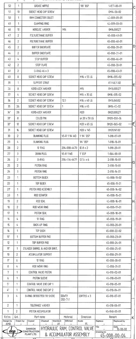
41 APPENDIX HPH4500 HYDRAULIC HAMMER PARTS LISTS FOR ALL CONFIGURATIONS This includes the following drawings: Basic Hammer Configuration Hammer Configured to Drive Tubes/Pipe with the. Universal Guide System Free Hanging Hammer Configured to Operate in Leads Hammer Configured With Leg Guides Leg Guides Sub Assembly Hydraulic Ram, Control Valve & Accumulator Assy Top Sensor Assembly Bottom Sensor Assembly Over Travel Trip Assembly Over Travel Valve.
42 Qnt. Revision Date Intro. Appr.by Design by Drawn by Copied Checked Standard Affirmed Scale Replace File Drawing no. Replaced by Date
43 Design by Drawn by Copied Checked Standard Affirmed Scale Replace File Drawing no. Replaced by Date
44 Qnt. Revision Date Intro. Appr.by Design by Drawn by Copied Checked Standard Affirmed Scale Replace File Drawing no. Replaced by Date
45 Design by Drawn by Copied Checked Standard Affirmed Scale Replace File Drawing no. Replaced by Date
46 Design by Drawn by Copied Checked Standard Affirmed Scale Replace File Drawing no. Replaced by Date
47 Qnt. Revision Date Intro. Appr.by Design by Drawn by Copied Checked Standard Affirmed Scale Replace File Drawing no. Replaced by Date
48 Qnt. Revision Date Intro. Appr.by Design by Drawn by Copied Checked Standard Affirmed Scale Replace File Drawing no. Replaced by Date
49 Qnt. Revision Date Intro. Appr.by Design by Drawn by Copied Checked Standard Affirmed Scale Replace File Drawing no. Replaced by Date
50 Design by Drawn by Copied Checked Standard Affirmed Scale File Date Replace Drawing no. Replaced by

51
52
53
54
55 Design by Drawn by Copied Checked Standard Affirmed Scale File Date Replace Drawing no. Replaced by
56 Qnt. Revision Date Intro. Appr.by Design by Drawn by Copied Checked Standard Affirmed Scale Replace File Drawing no. Replaced by Date
57 Qnt. Revision Date Intro. Appr.by Design by Drawn by Copied Checked Standard Affirmed Scale Replace File Drawing no. Replaced by Date
58 Design by Drawn by Copied Checked Standard Affirmed Scale File Date Replace Drawing no. Replaced by
59
60
61 APPENDIX HYDRAULIC HOSE DETAILS FOR HPH4500 HAMMER
62
63
64 APPENDIX 8.2 ACCUMULATOR PARTS LIST AND INSTRUCTIONS
65 Qnt. Revision Date Intro. Appr.by 1207 (N.T.S) Ø50 Ø110 M10 CAPACITY: DESIGN PRESSURE: TEST PRESSURE: WEIGHT: SEALS: OPERATING FLUID/S: SAFETY DEVICE: 9.5 LITRES 280 BARG 420 BARG 80 NITRILE/PTFE MINERAL OIL NONE KG Design by Drawn by Copied Checked Standard Affirmed Scale Replace File Drawing no. Replaced by Date
66 1 of 4 Maintenance Instructions Piston Accumulators HS Type General Introduction All piston accumulators supplied by Fawcett Christie Hydraulics (FCH) are manufactured individually for each and every contract. Due to the vast range of sizes, pressures and operating parameters and conditions it is impossible to record and document product reliability. Under normal operating conditions we would expect the life of the mechanical parts of a piston accumulator to exceed 20 years, and as long as the vessel is protected from the environment and is not subject to external damage. The seals and bearings would normally be expected to have a life of 4 years without replacement. However this would depend on the operating parameters, the condition of the operating fluid and to some extent the operating temperature. If for instance the operating fluid is very clean then this would extend life considerably, however if the operating fluid was badly contaminated then the seals could wear out in a matter of months. FCH make the following recommendation Annually a. Inspect the external surfaces of the vessel for corrosion and/or damage. b. Test the full operation of the piston accumulator 4 yearly a. Remove the gas end cap, fluid end cap & piston. b. Inspect cylinder bore & internals for wear/corrosion. c. Re-assemble with new seal kit (piston seals, wear rings and end cap seals) & pressure test. Warning Before attempting any maintenance on a piston accumulator, all fluid and gas pressure must be completely released. Fluid pressure should be released to tank or drained, gas pressure should be vented/released to atmosphere. If a gas valve is fitted, then a FCH nitrogen charging/discharging set (or similar) should be used. Dismantling Procedure Whenever possible, the accumulator should be removed from the installation and taken to a clean area workshop. The smaller vessels can be dismantled in the horizontal plane, but due to the weight of the end caps and piston on the larger vessels, it is recommended to dismantle and reassemble in the vertical plane.
67 2 of 4 1. Socket head set screw (item A on Fig 1.0) where lifted, should be removed from each end cap being stripped. 2. End cap removal tool should be lifted to M16 tapped holes in gas end cap. If blanking screws are lifted to end cap, then these will have to be removed as end cap removal tool uses these holes. The fluid end cap to be removed in the same manner. Fig End cap should be carefully unscrewed. A feature of the design is that there is a safety gas release vent in each end cap, which will vent any residual gas well before end cap thread becomes disengaged. If escaping gas can be heard, do not unscrew end cap any further until all the gas has been released. When approaching the end of the thread, care should be taken not to damage the last thread. End cap can be removed from the vessel. 4. M16 tapped rod should be screwed into tapped hole in recess of piston (item B on Fig 1.0) where fitted. Piston can then be pulled out of accumulator bore. Alternatively the piston can be driven carefully out of the bore form the opposite end by using a wooden drift. Care should be taken when the piston leaves the locating bore so as not to damage the piston seals, piston or the cylinder threads. Inspection All seals and bearing should be removed and inspected. It is recommended to fit a new seal kit on each strip down of the vessel. Honed section of the bore should be visually inspected for scoring. If any damage to the bore is apparent, then the vessel should be returned to FCH for further attention. All other components should be inspected for damage, particularly the threads of the cylinder and both end caps. Re-Assembly Procedure Note. Generally there are two types of piston seal used on FCH piston accumulator; these are the AQ seal and the GT seal. The AQ seal comprises a square section PTFE glyd ring, s quad ring and an energized o ring. The GT seal comprises a T section seal with split anti extrusion rings.
68 3 of 4 ( AQ Seal) 1. The o ring can be fitted to the piston. 2. Glyd ring requires to be stretched by heating before fitting. This can normally be done by immersion in boiling water, and then using gloves, fitting to the piston groove. Once the glyd ring is fitted to the piston groove, the piston should be inserted into the piston locating tool/sleeve to ensure that the glyd ring retains its normal size. 3. Piston should be removed from the locating tool when glyd ring has cooled. Quad ring can now be filled to the glyd ring, and care should be taken to ensure that it is not twisted. Bearing strips can now be filled to the piston. 4. Piston should now be inserted into the piston locating tool on the bench. Tool should be lubricated liberally with hydraulic fluid or suitable assembly compound/solution prior to filling piston. 5. Locating sleeve and piston can be inserted into end of accumulator cylinder, again firstly ensure that cylinder bore is well lubricated. Piston can now be tapped gently into the accumulator bore. Once fully located in the bore, locating sleeve can be removed. At this point it is recommended to check for good piston movement. ( GT Seal) 1. Main T seal and anti extrusion rings can be filled to the piston groove. 2. Bearing strips can be filled. 3. Piston should now be inserted into the piston locating tool on the bench. Tool should be lubricated liberally with hydraulic fluid or suitable assembly compound/solution prior to filling piston. 4. Locating sleeve and piston can be inserted into end of accumulator cylinder, again firstly ensure that cylinder bore is well lubricated. Piston can now be tapped gently into the accumulator bore. Once fully located in the bore, locating sleeve can be removed. At this point it is recommended to check for good piston movement. (End Caps) 1. It is recommended to fit new o rings and anti extrusion rings on each strip down 2. End cap thread and cylinder thread should be smeared with anti-seize compound. The o ring locating diameter should be smeared with hydraulic fluid, assembly compound or anti-seize compound. 3. End cap tool can be filled to end cap. End cap should be carefully offered to the cylinder until thread is located. Care should be in screwing the end cap over its full length, to ensure that thread seizure does not occur. End cap can be screwed fully home. 4. Anti-rotation screw (item A on Fig 1.0) can be re-filled where applicable. Installation Piston accumulator can be filled back into position. Nitrogen charging of the vessel should be done in accordance with normal hydraulic accumulator pre-charging practice. Gas Bottles Maintenance of these vessels is restricted to the replacement of the end cap seals on only. The procedure for the removal and refilling of the end caps is as for piston accumulators.
69 4 0f 4 Long Term Preservation After installation of piston accumulators and/or gas bottles, an inspection of all painted surfaces should take place and where necessary local repair work should be undertaken to avoid corrosion and resulting adverse effects. This should be done whenever servicing has been carried out. Internal Protection for Long Term Storage If units are to be stored for long periods of time, we advise that they should be stood vertically, and a rust preventative be applied through the end cap ports. It is recommended that the piston be cycled several times every 6 months. This can be done using low pressure nitrogen typically 10 bar. Recommended rust preventative: 0 to 12 months protection - Use vapour space inhibitor QP 40 (Nickerson Lubricants) or similar. Use amount as specified by manufacturer. When the system fluid is water based and the vessel material is carbon steel, additional precautions need to be taken to prevent internal corrosion during extended storage periods. If the accumulator is to be stored on the shelf then the piston should be centralised, ie mid-stroke, and both sides filled with fluid to exclude air and sealed. System fluid HW 443 should be used as it contains a vapour phase inhibitor (VFI). Better still is the use of Oceanic EFF which is specially formulated for preservation during long term storage. The above are general recommendations only. Where severe conditions are prevalent special precautions might need to be considered.
 unless sent via air-freight in which case they will be shipped unprecharged 3. Always use the gas filling apparatus supplied by Dawson.")
70 Important Safety Notes for Accumulators 1. Use nitrogen gas only 2. All accumulators are supplied precharged to 100bar (1450 psi) unless sent via air-freight in which case they will be shipped unprecharged 3. Always use the gas filling apparatus supplied by Dawson. This equipment includes a regulator valve specifically designed for use with hammer accumulators where the precharge pressure is less than the supply cylinder pressure. 4. Read the instructions below fully before attempting to adjust the precharge in any accumulator 5. Routine maintenance on the accumulator in-situ or removal of the accumulator must only be carried out when the hydraulic system pressure has been completely removed. Accumulator Pre-charge Pressure High pressure accumulator 100 bar Low Pressure Accumulator 3 bar Pre-charge Procedure 1. Attach the Regulator Valve to the nitrogen cylinder see figure Attach the charging set (5) to the accumulator gas valve assembly (6) and connect charging hose (7) between the regulator and the charging set connection. 3. Back off handle (8) anticlockwise until loose. Check gas bleed valve (9) on charging set is closed and screw hand wheel (10) clockwise to open gas valve. 4. Open nitrogen cylinder valve by turning key (11), cylinder pressure will register on right hand gauge (12). This pressure should be checked against the required precharge pressure. 5. Turn handle (8) clockwise until outlet pressure on left hand gauge (13) registers 10% higher than required precharge pressure (110 bar or 3.5 bar). When pressure on the charging set and outlet gauges are equal, close nitrogen cylinder valve. 6. Turn hand wheel (10) anticlockwise to seal gas valve. 7. Crack bleed valve (9) to exhaust gas from charging hose and remove hose from charging set and replace hose connection sealing cap. 8. Close bleed valve, turn hand wheel (10) clockwise to open gas valve and crack bleed valve (9) to vent down to required precharge pressure. Close bleed valve. 9. Turn hand wheel (10) anticlockwise to reseal gas valve, crack bleed valve and remove charging set from the accumulator. 10. Test accumulator gas valve for leaks using soapy water or similar.
71 Inspection and repair of Accumulators Due to the nature of the design and specific assembly procedures it is recommended that the accumulators should only be inspected and repaired by a competent person. Dawson Construction Plant Limited or their approved dealers will be happy to undertake this work as required. Please note the Important Safety Notes at the beginning of this section. Removal of Accumulator Pre-charge Connect Charging Set to the Gas Valve Assembly Release all the gas pressure by opening the Bleed Valve (Item 9 on the gas Charging Set) Disconnect the Charging Set from the Accumulator Removal of Accumulator Top See maintenance instructions piston accumulator page 2 of 4. Cleaning and Inspection Clean all metallic components with an organic solvent do not use on rubber components Inspect seals and bearing strips for damage and replace as appropriate. Inspect the inside of accumulator housing for signs of corrosion / mechanical damage. Replace any parts found or considered to be defective. If the unit was removed from the system the connecting O-Rings should be replaced irrespective of condition. After re-assembling the accumulator is ready to be Pre-charged see details at the top of this section. PRIOR TO APPLYING HYDRAULIC PRESSURE TO THE SYSTEM THE ACCUMULATOR MUST BE PRECHARGED WITH NITROGEN IN ACCORDANCE WITH THE ABOVE INSTRUCTIONS. FAILURE TO DO SO WILL RESULT IN FAILURE OF THE SYSTEM.
72 Appendix Energy Monitoring System (EMS) instructions and parts list (optional fit)


73 An overview of the system The system works by measuring the velocity of the drop weight just before impact. This value is used, along with the known ram weight, to calculate the kinetic energy of the ram weight before each impact. To measure the velocity of the drop weight, two magnetic sensors are used to sense a corrugated profile that has been machined into the drop weight. As the corrugations pass the sensors a chain of pulses is generated. The on hammer electronics then condition the pulses, perform some calculations, and format the information. The information is then sent to the display unit in the power pack either via a radio link or a wire link. Power for the system is provided by 6 batteries (Duracell D type) these are mounted inside the hammer electronics enclosure, battery life is 1000 hours +. A pressure switch mounted on the main hydraulic valve block turns on the system. The system turns off automatically 3-4 minutes after hydraulic pressure is removed. System Operation The system can communicate between the hammer and display via either radio or wire link. Decide which is most appropriate for the particular job. Radio + No physical connection between power pack and hammer - Needs clear line of sight between hammer antenna and power pack antenna - Will not work underwater Wire + Will work underwater + Will not be affected by obstructions between hammer and pack - Requires physical connection Setting the hammer for radio or wire link: EMS Processor Unit Positioned on the hammer casing on the OTHER side to the hose inlet manifold Plug going to the antenna for radio link OR plug going to socket on hydraulic inlet manifold for wire link. If using wire link, the wire to the power pack plugs in here (hydraulic inlet manifold)
 Plug in antenna for radio link OR wire from hose inlet manifold for wire link.")
. Bottom display - live blow counter.")

 Bottom display - total blows since last reset.")
74 Setting the power pack end for radio or wire link: If using radio link, position the antenna on pack top. (magnetic mounted) Plug in antenna for radio link OR wire from hose inlet manifold for wire link. Using the system The display has three modes - Running, Lap, and Reset. Running: Top display - last blow energy. Middle display - blows per minute (averaged over the last 5 blows). Bottom display - live blow counter. Lap: Top display - average blow energy over the last lap. Middle display - frozen blows per minute. Bottom display - frozen lap count preceded by a letter L as an indication of lap state. Reset: Top display - radio signal strength 0-100% Middle display - monitor battery strength (0-9.0V) Bottom display - total blows since last reset. Switching modes Press the lap button for less than 1 second to toggle the display between running and lap mode. (the lap counters are reset on entry into the lap mode). Holding the lap button for more than 1 second will cause the unit to enter the reset mode (remains in the reset state until the button is released)
, this is mounted on the hammer casing on the OTHER side to")


75 System maintenance Every 500 hours a. Replace the 6 duracell type D batteries. Remove the lid of the processor unit (4 M6 nyloc nuts), this is mounted on the hammer casing on the OTHER side to the hydraulic hose inlets. Note the orientation before removing the old batteries. Ensure the protective tape to prevent the batteries from chafing on the steel supports is in place. c. Check all plugs and sockets are screwed up tightly and cabling is in good condition. d. Check the two magnetic sensors for physical damage, also measure their resistance. This should be between ohms. (across pins 1-2 and 3-4 on the 4 pin plug) Replace the complete sensor assembly if there are any signs of damage.
HPH 1200 HYDRAULIC HAMMER
 HPH 1200 HYDRAULIC HAMMER INNOVATIVE PILING EQUIPMENT HYDRAULIC PILING HAMMERS EXCAVATOR MOUNTED VIBRATORS EXCAVATOR MOUNTED DRILLS QUIET, VIBRATIONLESS PUSH-PULL PILING PILE EXTRACTION SHEET PILE GUIDE
HPH 15000e HYDRAULIC HAMMER
 HPH 15000e HYDRAULIC HAMMER INNOVATIVE PILING EQUIPMENT HYDRAULIC PILING HAMMERS USER S MANUAL & PARTS LIST EXCAVATOR MOUNTED VIBRATORS EXCAVATOR MOUNTED DRILLS QUIET, VIBRATIONLESS PUSHPULL PILING PILE
HPH2400E HYDRAULIC HAMMER
 HPH2400E HYDRAULIC HAMMER INNOVATIVE PILING EQUIPMENT USER S MANUAL & PARTS LIST HYDRAULIC PILING HAMMERS EXCAVATOR MOUNTED VIBRATORS EXCAVATOR MOUNTED DRILLS QUIET, VIBRATIONLESS PUSH-PULL PILING PILE
 AUTOGARD SERIES 820 TORQUE LIMITER Installation and Maintenance Manual DB0009 Issue 11 21 Feb 2017 British Autogard Ltd 2 Wilkinson Rd., Love Lane Industrial Estate, Cirencester, Glos., GL7 1YT UK Tel.
IMPORTANT INSTRUCTIONS FOR OPERATION & MAINTENANCE OF
 IMPORTANT INSTRUCTIONS FOR OPERATION & MAINTENANCE OF CONVEYORS EASIKIT 300 EASIKIT 450 EASIKIT 600, 900, 1200 & 1500 The manufacturer does not accept responsibility for any loss, damage to other equipment,
HYDRAULIC QUICK HITCH
 HYDRAULIC QUICK HITCH Installation & Operation Manual Important: This manual must be kept with the excavator at all times and referred to as required Harford Attachments Ltd Table of Contents Introduction
LOG CHOP. Hydraulic Wood Guillotine. Owners Illustrated Instruction Book & Parts List
 LOG CHOP Hydraulic Wood Guillotine Owners Illustrated Instruction Book & Parts List Grovebury Road, Leighton Buzzard, Bedfordshire. LU7 4UX. UK. Tel:01525 375157. Fax:01525 385222. Email: enquires@brownsagricultural.co.uk
OPERATION AND PARTS MANUAL
 OPERATION AND PARTS MANUAL MODEL NUMBER : PART NUMBER : GTL 1110 1900-0510 SERIAL NUMBER : BAYNE MACHINE WORKS, INC. PHONE: (864) 288-3877 910 FORK SHOALS ROAD TOLL FREE: (800) 535-2671 GREENVILLE S.C.,
3.25 Ton Heavy Duty Floor Jack
 Please dispose of packaging for the product in a responsible manner. It is suitable for recycling. Help to protect the environment, take the packaging to the local amenity tip and place into the appropriate
OCTOPUS SELECTION & INSTALLATION GUIDE Rev. C CRA SERIES CONTINUOUS RUNNING PUMPSET
 A. GENERAL DESCRIPTION: OCTOPUS SELECTION & INSTALLATION GUIDE Rev. C CRA SERIES CONTINUOUS RUNNING PUMPSET Octopus CRA continuous running pumps are very reliable quiet and efficient devices which will
26 - COOLING SYSTEM CONTENTS ENGINE COOLING - DESCRIPTION... 3 ENGINE COOLING - OPERATION... 9 COOLING SYSTEM FAULTS... 1
 26 - COOLING SYSTEM CONTENTS Page LAND ROVER V8 DESCRIPTION AND OPERATION ENGINE COOLING - DESCRIPTION... 3 ENGINE COOLING - OPERATION... 9 FAULT DIAGNOSIS COOLING SYSTEM FAULTS... 1 REPAIR COOLANT - DRAIN
Service/Inspection Checklist and Report
 Fastrac 2155 and 2170 Service/Inspection Checklist and Report Fastrac 2155 and 2170 Issued by JCB Technical Publications, JCB Service, World Parts Centre, Beamhurst, Uttoxeter, Staffordshire, ST14 5PA,
Maintenance and Repair
 Maintenance and Repair WARNING ALWAYS shut off the engine, remove key from ignition, make sure the engine is cool, and disconnect the spark plug and positive battery terminal from the battery before cleaning,
PRODUCT SUMMARY INNOVATIVE PILING EQUIPMENT. Est
 PRODUCT SUMMARY INNOVATIVE PILING EQUIPMENT 40 Est. 19742014 HYDRAULIC PILING HAMMERS Principal Advantages. Unrivalled production rates rapid blow rates save time and money, shortening project duration.
JACKALL HYDRAULIC SYSTEM
 JACKALL HYDRAULIC SYSTEM FIG. 1. Layout of a typical installation. Servicing Instructions for Red Jackall. The Red Jackall hydraulic system requires no attention other than a periodical examination of
Fuel and exhaust systems 4A 21
 Fuel and exhaust systems 4A 21 15.40 Unscrew the union nuts and disconnect the fuel feed and return hoses from the manifold 41 Disconnect the injector wiring harness connector and the vacuum hose from
Purging Air From Divider Block Lubrication Systems
 FROST ENGINEERING SERVICE Purging Air From Lubrication Systems A D I V I S I O N O F G E C S E Y S A L E S & S E R V I C E DESCRIPTION Divider block lubrication systems operate correctly only when all
VS403 INSTRUCTIONS FOR: VACUUM AND PRESSURE TEST / BRAKE BLEEDING UNIT MODEL: SAFETY INSTRUCTIONS INTRODUCTION & CONTENTS. fig.1
 INSTRUCTIONS FOR: VACUUM AND PRESSURE TEST / BRAKE BLEEDING UNIT MODEL: VS403 Thank you for purchasing a Sealey product. Manufactured to a high standard this product will, if used according to these instructions
Operating and Installation Instructions Diaphragm Vacuum Pumps and Compressors
 Operating and Installation Instructions Diaphragm Vacuum Pumps and Compressors Type range: UN813.3ANI UN813.4ANI UN813.3ANDCB UN813.4ANDCB UN813.5ANI Fig. 1: UN813.3ANI Fig. 2: UN813.4ANI You have selected
NECO Pumping Systems
 INSTALLATION OPERATION & MAINTENANCE INSTRUCTIONS For Your NECO Pumping Systems PACKAGED CIRCULATING SYSTEM THIS COMPLETELY ASSEMBLED, TESTED, PACKAGED CIRCULATING SYSTEM IS OF THE HIGHEST QUALITY AND
Ideal Installation. I & M Mark 67 (1/2 6 ) Control Line. Installation & Maintenance Instructions for Mark 67 Pressure Regulators
 Control Line. Installation & Maintenance Instructions for Mark 67 Pressure Regulators") I & M Mark (/ ) 0 Wasson Road Cincinnati, OH 0 USA Phone --00 Fax -8-00 info@richardsind.com www.jordanvalve.com Installation & Maintenance Instructions for Mark Pressure Regulators Warning: Jordan Valve
I & M Mark (/ ) 0 Wasson Road Cincinnati, OH 0 USA Phone --00 Fax -8-00 info@richardsind.com www.jordanvalve.com Installation & Maintenance Instructions for Mark Pressure Regulators Warning: Jordan Valve
Troubleshooting the Transmission Hydraulic System
 Testing and Adjusting IT28F INTEGRATED TOOLCARRIER POWER TRAIN Testing And Adjusting Introduction Reference: For Specifications with illustrations, refer to SENR5974, IT28F Integrated Toolcarrier Power
Hydraulic Motorcycle Lift. Model CML3 & CML3 AIR Part No: ASSEMBLY & OPERATING INSTRUCTIONS 0212
 Hydraulic Motorcycle Lift. Model CML3 & CML3 AIR Part No: 7610143 ASSEMBLY & OPERATING INSTRUCTIONS 0212 DO NOT ENTER UNDER THE PLATFORM UNLESS IT IS MECHANICALLY LOCKED (see instructions) DO NOT EXCEED
APT14 Automatic Pump Trap Installation and Maintenance Instructions
 6120250/7 IM-P612-04 ST Issue 7 APT14 Automatic Pump Trap Installation and Maintenance Instructions 1 Product information 2 Operation 3 Installation Closed loop steam systems only 4 Commissioning 5 Maintenance
RELEASING PRESSURE IN THE HYDRAULIC SYSTEM,
 Testing And Adjusting Introduction NOTE: For Specifications with illustrations, make reference to SPECIFICATIONS for 225 EXCAVATOR HYDRAULIC SYSTEM, Form No. SENR7734. If the Specifications are not the
2 Ton - 50 Ton Bottle Jack
 Please dispose of packaging for the product in a responsible manner. It is suitable for recycling. Help to protect the environment, take the packaging to the local amenity tip and place into the appropriate
TWO-STAGE HYDRAULIC PUMP. RWP55-IBT-Air
 ORIGINAL INSTRUCTIONS Form No.1000458 5 SPX Corporation 5885 11th Street Rockford, IL 61109-3699 USA Tech. Services: (800) 477-8326 Fax: (800) 765-8326 Order Entry: (800) 541-1418 Fax: (800) 288-7031 Internet
3 Ton Trolley Jack. Please read and fully understand the instructions in this manual before operation. Keep this manual safe for future reference.
 Please dispose of packaging for the product in a responsible manner. It is suitable for recycling. Help to protect the environment, take the packaging to the local amenity tip and place into the appropriate
Installation, Operating, Maintenance and Safety Instructions for CW332 Pressurised water system for boats 24 volt d.c.
 24V DC-CW332 DOC531/11 Installation, Operating, Maintenance and Safety Instructions for CW332 Pressurised water system for boats 24 volt d.c. To obtain the best performance from your Pressurised water
OPERATION AND PARTS MANUAL
 OPERATION AND PARTS MANUAL MODEL NUMBER : PART NUMBER : GRL 1110 1900-0540 SERIAL NUMBER : BAYNE MACHINE WORKS, INC. PHONE: 864.288.3877 910 FORK SHOALS ROAD TOLL FREE: 800.535.2671 GREENVILLE SC, 29605
SERIES OPERATION AND MAINTENANCE MANUAL
 SERIES OPERATION AND MAINTENANCE MANUAL This manual CONTAINS IMPORTANT WARNINGS, S and OTHER INSTRUCTIONS. Read and understand the instruction manual Carefully, before use and retain it for reference.
DENISON HYDRAULICS open loop pump controls series P140 A-mod, P260 B-mod service information
 DENISON HYDRAULICS open loop pump controls series P10 A-mod, P260 B-mod service information Publ. S1-AM02-A replaces S1-AM02 01-97 CONTENTS typical characteristics-------------------------------------------------------------------------------
OPERATING INSTRUCTIONS & SERVICE MANUAL BLUE MAX II HYDROSTATIC TEST PUMP
 PAGE 1 OF 10 OPERATING INSTRUCTIONS & SERVICE MANUAL BLUE MAX II HYDROSTATIC TEST PUMP EFFICIENT, EASY OPERATION Air operated pump Wide range of pressures and volumes Easy to operate controls Output pressure
HEAVY DUTY PNEUMATIC TORQUE WRENCH (C-RAD) USER GUIDE
 USER GUIDE") HEAVY DUTY PNEUMATIC TORQUE WRENCH (C-RAD) USER GUIDE Ref: WCOI.041 Date: June 2015 Issue: 4 Page Description CONTENTS 1 Introduction Training Requirements 2 General Safety 3 C-RAD Wrench Models Covered
HEAVY DUTY PNEUMATIC TORQUE WRENCH (C-RAD) USER GUIDE Ref: WCOI.041 Date: June 2015 Issue: 4 Page Description CONTENTS 1 Introduction Training Requirements 2 General Safety 3 C-RAD Wrench Models Covered
Installation and Operational Instructions for ROBATIC -clutch Type and Type Sizes 3 9
 Please read the Operational Instructions carefully and follow them accordingly! Ignoring these Instructions may lead to malfunctions or to clutch failure, resulting in damage to other parts. Contents:
Sub Section Title Page No.
 Sub Section Title Page No. 1 Introduction 3 2 Routine Maintenance 3 3 Disassembly 4 3.1 Disassembly of Double Crank Design 4 3.2 Disassembly of Scotch Yoke Design 5 3.3 Disassembly of Actuator Cylinder
EMV-70 EXCAVATOR MOUNTED VIBRATOR
 EMV-70 EXCAVATOR MOUNTED VIBRATOR INNOVATIVE PILING EQUIPMENT HYDRAULIC PILING HAMMERS OPERATORS INSTRUCTIONS & SPARE PARTS LIST EXCAVATOR MOUNTED VIBRATORS EXCAVATOR MOUNTED DRILLS QUIET, VIBRATIONLESS
N G 3 S p r i n g B r a k e s
 C o m m e r c i a l V e h i c l e S y s t e m s P r o d u c t M a n u a l N G 3 S p r i n g B r a k e s R ationalised Units for S-Cam Applications P r o d u c t M a n u a l Disclaimer The information contained
1/4 Die Grinder. Please read and fully understand the instructions in this manual before operation. Keep this manual safe for future reference
 Please dispose of packaging for the product in a responsible manner. It is suitable for recycling. Help to protect the environment, take the packaging to the local amenity tip and place into the appropriate
TC Series Cooling Systems
 TC Series Cooling Systems Table of Contents Table of Contents...1 List of Figures...1 Safety...2 Introduction...2 General Specifications...2 Types of Coolant...2 Routine Maintenance...2 Surge Tank Coolant
Valvetrain, servicing
 Page 1 of 51 15-32 Valvetrain, servicing Note: Cylinder heads with small cracks between the valve seats that are less than 0.3 mm (0.012 in.) wide and/or between one valve seat and only the first 4 threads
PETROL GENERATOR PGH2200, PGH3000, PGH6500 OWNER S MANUAL FOR YOUR SAFETY PLEASE READ THESE INSTRUCTIONS CAREFULLY AND RETAIN THEM FOR FUTURE USE.
 PETROL GENERATOR OWNER S MANUAL PGH2200, PGH3000, PGH6500 FOR YOUR SAFETY PLEASE READ THESE INSTRUCTIONS CAREFULLY AND RETAIN THEM FOR FUTURE USE. WARRANTY GENERATOR SAFETY This generator is covered by
Troubleshooting The Transmission Hydraulic System
 416B, 426B, 428B, 436B, & 438B BACKHOE LOADERS TRANSMISSION Testing And Adjusting Troubleshooting The Transmission Hydraulic System Make reference to the following warning and pressure tap locations for
PETROL GENERATOR SPG2200, SPG3000, SPG6500 OWNER S MANUAL FOR YOUR SAFETY PLEASE READ THESE INSTRUCTIONS CAREFULLY AND RETAIN THEM FOR FUTURE USE.
 PETROL GENERATOR OWNER S MANUAL SPG2200, SPG3000, SPG6500 FOR YOUR SAFETY PLEASE READ THESE INSTRUCTIONS CAREFULLY AND RETAIN THEM FOR FUTURE USE. WARRANTY This generator is covered by a 24 month warranty
OCTOPUS SELECTION & INSTALLATION GUIDE
 OCTOPUS SELECTION & INSTALLATION GUIDE CRB SERIES CONTINUOUS RUNNING PUMPSET A. GENERAL DESCRIPTION: Octopus CRB pumpsets are heavy duty, continuously running, electric motor driven pumps which are used
VLW18TE, VLW18TI HYDRAULIC VERTICAL LIFTING WEDGES. Operator Instruction Manual INNOVATION IN ITS MOST FUNCTIONAL FORM
 VLW18TE, VLW18TI HYDRAULIC VERTICAL LIFTING WEDGES Operator Instruction Manual info@equalizerinternational.com www.equalizerinternational.com INNOVATION IN ITS MOST FUNCTIONAL FORM INDEX SECTION CONTENTS
ABSOLUTE EQUIPMENT PTY LTD
 Manual Hydraulic Toe Jack Model DTJ Series ABSOLUTE EQUIPMENT PTY LTD 2/186 Granite Street, GEEBUNG QLD 4034 Australia sales@absoluteequipment.com.au Phone: +61 7 3865 4006 Fax: +61 7 3102 6288 This is
Constant Running Hydraulic Pump Installation Guide. Document Number: Date: March 2006
 Constant Running Hydraulic Pump Installation Guide Document Number: 87039-2 Date: March 2006 2 CR Hydraulic Pump - Installation Guide Important information Drives covered M81126 - Raymarine Constant Running
ABSOLUTE EQUIPMENT PTY LTD
 Manual Hydraulic Toe Jack Model DTJ Series ABSOLUTE EQUIPMENT PTY LTD 2/186 Granite Street, GEEBUNG QLD 4034 Australia sales@absoluteequipment.com.au Phone: +61 7 3865 4006 Fax: +61 7 3102 6288 This is
INSTALLATION MANUAL - v4
 I-LOCKTM COUPLER INSTALLATION MANUAL - v4 SPECIAL NOTE Your new Wedgelock Coupler fitted with the I-LOCK TM Safety Device requires the installation of a third hydraulic line - please follow the instructions
BCV30 DN20 - Blowdown Control Valve Installation and Maintenance Instructions
 4034450/9 IM-P403-15 AB Issue 9 BCV30 DN20 - Blowdown Control Valve Installation and Maintenance Instructions 1. Safety information 2. Application 3. Technical data 4. Operation 5. Installation 6. Rotating
CONTENTS. Product Features and Specifications Installation Requirement Installation Exploded View Operation Instruction...
 1 CONTENTS Product Features and Specifications... 3 Installation Requirement... 5 Installation... 6 Exploded View... 20 Test... 22 Operation Instruction... 25 Maintenance... 26 Trouble Shooting... 27 Parts
Installation & Operation Manual
 Installation & Operation Manual Thank you for purchasing our AS4795.1 Butterfly Valve. Before installing or operating, please carefully read this manual to know thoroughly how to install or operate. The
SYSTEM SAVER 318 AIR COMPRESSOR FOR MACK E-TECH AND ASET ENGINES MAINTENANCE MANUAL
 SYSTEM SAVER 318 AIR COMPRESSOR FOR MACK E-TECH AND ASET ENGINES MAINTENANCE MANUAL NON-THROUGH DRIVE THROUGH DRIVE Service Notes About This Manual This manual provides service and repair procedures for
PRECISION UK Ltd DUPLEX AGSS PLANT
 DUPLEX AGSS PLANT Contents Page Section Page Product Description General 3 AGSS Plant 3 AGSS Remote Switch 3 Operation General 4 Safety General 5 Installation General 5 Mechanical 5 Electrical 7 Wiring
BELT CONVEYOR CB/M5 Series
 BELT CONVEYOR CB/M5 Series User and maintenance manual 1 DECLARATION OF CONFORMITY The company: Tel. +39-0444 450 620-451 520 Fax +39-0444 671 840 declares under its own responsibility that the machine
GMR-S and GMR40-S Disc Brake Caliper - Spring Applied, Air Released
 (GMR) 9 (GMR) ø GMR-S and GMR-S Disc Brake Caliper - Spring Applied, Air Released DB Nominal dimensions given. For specific dimensions please contact Twiflex Limited. For GMR Mk caliper details see DB
Air Operated Diaphragm Pumps Operating and Maintenance Instructions
 Product & Chemical Disclaimer The user must take responsibility in the selection of the products materials of construction. Empire Pumps Ltd will act in an advisory role and offer recommendations; however,
AN EXPLANATION OF CIRCUITS CARTER YH HORIZONTAL CLIMATIC CONTROL CARBURETER
 AN EXPLANATION OF CIRCUITS CARTER YH HORIZONTAL CLIMATIC CONTROL CARBURETER The Carter Model YH carbureter may be compared with a Carter YF downdraft carbureter with the circuits rearranged to operate
Installation Manual. Model T675A Engine Brakes. For Mack 6 Cylinder, 2 valve Head ENDT-673, 675, 676 & E6 Series Engines.
 Engine Brakes Installation Manual Model T675A Engine Brakes For Mack 6 Cylinder, 2 valve Head ENDT-673, 675, 676 & E6 Series Engines TecBrake P.O. Box 27822 Houston, Texas 77227 INSTALLATION MANUAL TECBRAKE
User Guide IM/TORBAR-EN Rev. D. Averaging pitot tubes
 User Guide IM/TORBAR-EN Rev. D Torbar The Company We are an established world force in the design and manufacture of measurement products for industrial process control, flow measurement, gas and liquid
Breezair TBA 550 Installation Manual
 Breezair TBA 550 Installation Manual Table of Contents ITEM Safety Instructions Specifications Exploded View of the Air Cooler Components of the Air Cooler Dismantling the Air Cooler Installing the Transition
Instructions for: FOLDING ENGINE CRANE PREMIER 2 TONNE. MODEL No: SPC2000
 Instructions for: FOLDING ENGINE CRANE PREMIER 2 TONNE MODEL No: SPC2000 Thank you for purchasing a Sealey product. Manufactured to a high standard, this product will, if used according to these instructions,
E-M Series. Combined Manual and Automatic Engine Overspeed Shut Down Valves
 E-M Series Combined Manual and Automatic Engine Overspeed Shut Down Valves A range of easily installed diesel engine air intake valves which automatically close on engine overspeed and also incorporate
80 Litre Suction Oil Drainer With Inspection Chamber
 Please dispose of packaging for the product in a responsible manner. It is suitable for recycling. Help to protect the environment, take the packaging to the local amenity tip and place into the appropriate
DB4604 GMR-SD and GMR40-SD Disc Brake Caliper - Spring Applied, Air Released
 DB464 GMR-SD and GMR4-SD Disc Brake Caliper - Spring Applied, Air Released Nominal dimensions given. For specific dimensions please contact Twiflex Limited. For GMR Mk 2 caliper details see DB 364 Air
 WINCH OPERATING PRACTICES 1. Read the manufacturer's instructions before operating the winch. 2. Always inspect, test maintain and operate this winch in accordance with American National Standards Institute
Sub Section Title Page No. 1 Introduction 3. 2 Significant Equipment Detail 3. 3 Installation Guidelines 4. 4 Routine Maintenance 4
 CONTENTS: Sub Section Title Page No 1 Introduction 3 2 Significant Equipment Detail 3 3 Installation Guidelines 4 4 Routine Maintenance 4 5 Disassembly of the Choke Valve 6 Component Inspection 6 7 Reassembly
SECTION 6A1-2 - ENGINE MECHANICAL - V6 SUPERCHARGED
 SECTION 6A1-2 - ENGINE MECHANICAL - V6 SUPERCHARGED CAUTION: This vehicle will be equipped with a Supplemental Restraint System (SRS). A SRS will consist of either seat belt pre-tensioners and a driver
Troubleshooting, Service Tips, And Major Improvements For Hydrostatic Transmissions (Special Edition){3200}
{3200}") Page 1 of 75 Troubleshooting, Service Tips, And Major Improvements For Hydrostatic Transmissions (Special Edition){3200} 943, 953, 963, 973 Loaders Introduction The hydrostatic transmissions used in 943,
Page 1 of 75 Troubleshooting, Service Tips, And Major Improvements For Hydrostatic Transmissions (Special Edition){3200} 943, 953, 963, 973 Loaders Introduction The hydrostatic transmissions used in 943,
1999 Toyota RAV BRAKES Disc & Drum - Trucks & Vans
 DESCRIPTION & OPERATION 1999-2000 BRAKES Disc & Drum - Trucks & Vans WARNING: For warnings and procedures regarding vehicles equipped with Anti-Lock Brake Systems (ABS), see appropriate ANTI-LOCK article.
Instruction Manual. Maximum Operating Pressure 510 bar
 Single Speed Diesel Power Unit Model HPD11 Maximum Operating Pressure 510 bar ABSOLUTE EQUIPMENT PTY LTD 2/186 Granite Street, GEEBUNG QLD 4034 Australia sales@absoluteequipment.com.au Phone: +61 7 3865
Standard Valves Series Globe Valves Series Angle Valves Series Way-Valves
 Installation, Operation, Maintenance Instructions Standard Valves Series 035 000 Globe Valves Series 031 000 Angle Valves Series 033 000 3-Way-Valves 1 GENERAL INFORMATION These instructions are designed
IMPORTANT FITTING INSTRUCTIONS PLEASE READ THESE INSTRUCTIONS BEFORE FITTING YOUR TURBO. FAILING TO FOLLOW THEM COULD INVALIDATE THE WARRANTY.
 IMPORTANT FITTING INSTRUCTIONS! PLEASE READ THESE INSTRUCTIONS BEFORE FITTING YOUR TURBO. FAILING TO FOLLOW THEM COULD INVALIDATE THE WARRANTY. 1WHY DID THE LAST TURBO FAIL? Turbochargers are very reliable:
ON LOAD GEARS OPERATIONAL AND MAINTENANCE MANUAL VACUUM CIRCUIT BREAKER TYPE VS12
 ON LOAD GEARS OPERATIONAL AND MAINTENANCE MANUAL VACUUM CIRCUIT BREAKER TYPE VS12 We thank you for having purchased VCB s from us. We are sure you will be very happy with the performance and service of
PNEUMATIC TORQUE WRENCH (C-RAD) USER GUIDE
 USER GUIDE") PNEUMATIC TORQUE WRENCH (C-RAD) USER GUIDE Ref: WCOI.031 Date: Mar 2017 Issue: 10 Page Description CONTENTS 1 Introduction Training Requirements 2 General Safety 3 C-RAD Wrench Models Covered By Manual
PNEUMATIC TORQUE WRENCH (C-RAD) USER GUIDE Ref: WCOI.031 Date: Mar 2017 Issue: 10 Page Description CONTENTS 1 Introduction Training Requirements 2 General Safety 3 C-RAD Wrench Models Covered By Manual
Your Guide to the Installation, Care and maintenance of PERFORMA. Electronic Self Closing Fittings - Mains Powered 886V (343029) 885V (343027)
 885V (343027)") Your Guide to the Installation, Care and maintenance of PERFORMA Electronic Self Closing Fittings - Mains Powered 886V (343029) 885V (343027) Pegler Limited, St Catherine s Avenue, Doncaster DN4 8DF Telephone
Your Guide to the Installation, Care and maintenance of PERFORMA Electronic Self Closing Fittings - Mains Powered 886V (343029) 885V (343027) Pegler Limited, St Catherine s Avenue, Doncaster DN4 8DF Telephone
Certificate of Incorporation (Typical)
") Certificate of Incorporation (Typical) Declaration We Varley Pump Limited hereby declare that the following machinery has been designed to be safely incorporated into other machinery and must not be put
Certificate of Incorporation (Typical) Declaration We Varley Pump Limited hereby declare that the following machinery has been designed to be safely incorporated into other machinery and must not be put
Brake Upgrade Kit Fitting Instructions Bonneville America
 WARNING: Always have Triumph approved parts, accessories and conversions fitted by a trained technician of an authorised Triumph Dealer. The fitment of parts, accessories and conversions by a technician
INSTALL MANUAL. FOR ON LINE ORDERING- E Commerce Visit Our Website
 INSTALL MANUAL FOR ON LINE ORDERING- E Commerce Visit Our Website WWW.PRESSUREGUARD.COM Contact Information Technical Support: Chris@pressureguard.com Sales Support: Sales@pressureguard.com By Phone: 615-227-6024
Safety, Operation and Maintenance Instructions For Long & Short Nose Upholstery Air Stapler (NS10 & NS11)
") Safety, Operation and Maintenance Instructions For Long & Short Nose Upholstery Air Stapler (NS10 & NS11) Important: Drop 3 drops of oil into the stapler air inlet BEFORE first use. See page 2. Please
Safety, Operation and Maintenance Instructions For Long & Short Nose Upholstery Air Stapler (NS10 & NS11) Important: Drop 3 drops of oil into the stapler air inlet BEFORE first use. See page 2. Please
TANKERS OPERATING & SAFETY INSTRUCTIONS FOR SPARE PARTS GO TO
 TANKERS OPERATING & SAFETY INSTRUCTIONS FOR SPARE PARTS GO TO WWW.MARSHALL-TRAILERS.CO.UK FOR MODELS: ST1200, ST1400, ST1600, ST1800, ST2000, ST2300, ST2550 CHARLES J. MARSHALL (ABERDEEN) LTD CHAPEL WORKS,
HGS SYSTEM Workshop Manual M103 01
 HGS SYSTEM Workshop Manual M0 0 HGS SYSTEM VERSION.0 EN/0-00 Autobusfabriek BOVA b.v. De Vest 9 5555 XL Valkenswaard The Netherlands Phone: + (0) 40 0846 Fax: + (0) 40 09477 E-mail: basis@bova.nl Website:
Table 6-1. Problems and solutions with pump operations. No Fluid Delivery
 Table 6-1. and solutions with pump operations No Fluid Delivery Fluid level in the reservoir is low. Oil intake pipe or inlet filter is plugged. Air leak in the inlet line prevents priming or causes noise
Instruction Manual Montage- und Betriebsanleitung Notice d utilisation
 Instruction Manual Montage- und Betriebsanleitung Notice d utilisation 2 Cast Fifth Wheel 2 Guss-Sattelkupplung Sellette 2 en fonte C O N N E C T Y O U R B U S I N E S S W I T H F O N T A I N E C O N T
INSTRUCTIONS FOR: VACUUM TESTER AND BRAKE BLEEDING KIT
 INSTRUCTIONS FOR: VACUUM TESTER AND BRAKE BLEEDING KIT MODEL: VS402 Thank you for purchasing a Sealey product. Manufactured to a high standard this product will, if used according to these instructions
Installation & Technical Guide. Domestic & Commercial.
 Installation & Technical Guide Domestic & Commercial www.challisbooster.com www.challisboosterplus.com Installation and Technical Guide Domestic and Commercial Challis Water Controls Europower House, Lower
HYDRAULIC PALLET TRUCK
 HYDRAULIC PALLET TRUCK Models; PT550C & PT685C Part Nos 7630172 & 7630177 OPERATING & MAINTENANCE INSTRUCTIONS GC05/12 INTRODUCTION Thank you for purchasing this CLARKE Pallet Truck. Before attempting
Installation and Operational Instructions for ROBATIC -clutch Types _.0 and _.0 Sizes 3 7
 Please read these Installation and Operational Instructions carefully and follow them accordingly! Ignoring these Instructions may lead to malfunction or to clutch failure, resulting in damage to other
DO NOT INSTALL, OPERATE, OR MAINTAIN AN ATI PRODUCT UNLESS TRAINED AND QUALIFIED IN PRODUCT AND ACCESSORY INSTALLATION, OPERATION AND MAINTENANCE.
 IOM Supplement IOMS003 ATI HO1/HO2 HYDRAULIC OVERRIDE Scope of Supplement This supplement is intended to assist those who are involved with the installation, operation and maintenance of ATI Linear Actuators
EQUALIZER International Limited 10T(I) Integral Hydraulic Spreading Wedge Repair Instruction Manual
 Integral Hydraulic Spreading Wedge Repair Instruction Manual") EQUALIZER International Limited 10T(I) Integral Hydraulic Spreading Wedge Repair Instruction Manual INDEX THE EQUALIZER 10T(I) Integral Hydraulic Wedge SECTION CONTENTS PAGE NO (S) 03 04 05 06 07 08 09
EQUALIZER International Limited 10T(I) Integral Hydraulic Spreading Wedge Repair Instruction Manual INDEX THE EQUALIZER 10T(I) Integral Hydraulic Wedge SECTION CONTENTS PAGE NO (S) 03 04 05 06 07 08 09
Tri-Spark Ignition System Installation Triple Cylinder TRI-0001
 Tri-Spark Ignition System Installation Triple Cylinder TRI-0001 There are potentially lethal high voltages produced at the ignition coils and spark plugs, therefore every precaution must be taken to prevent
HYDRAULIC PALLET TRUCK. MODEL No: PTE550 PART Nos OPERATION & MAINTENANCE INSTRUCTIONS
 HYDRAULIC PALLET TRUCK MODEL No: PTE550 PART Nos 7630171 OPERATION & MAINTENANCE INSTRUCTIONS 0604 Please read these instructions carefully before operating the truck Thank you for purchasing this CLARKE
INSTRUCTION MANUAL FOR SAMSON GAMMA UNITS, TYPES: GAMMA 10, -20, -30, -40, -50, -60, -70, -90, -100
 TRUCKS FOOD OFFSHORE FISH SAMSON LIQUID RING VACUUM PUMPS INSTRUCTION MANUAL FOR SAMSON GAMMA UNITS, TYPES: GAMMA 10, -20, -30, -40, -50, -60, -70, -90, -100 DOC3700C INDUSTRY GAMMA UNITS 2 CONTENTS 1
Tooling Assistance Center
 Safeguards are designed into this application equipment to protect operators and maintenance personnel from most hazards during equipment operation. However, certain safety precautions must be taken by
Air-Assist Service Jack Max. Capacity: 10 Tons
 Form No. 565786 Parts List & Operating Instructions for: 1511B Air-Assist Service Jack Max. Capacity: 10 Tons 109 67 66 68 77 69 70 78 95 94 107 106 108 26 71 72 72 93 X L 65 75 92 91 90 89 88 87 86 85
HOT WASHER MODEL NO: KING 125 OPERATION & MAINTENANCE INSTRUCTIONS PART NO: LS1009
 HOT WASHER MODEL NO: KING 125 PART NO: 7320170 OPERATION & MAINTENANCE INSTRUCTIONS LS1009 INTRODUCTION Thank you for purchasing this Hot Washer. This machine is a portable, high pressure power washer,
Svendborg Conveyor Brake Maintenance
 CLIENT LOGO OPF MAINTENANCE WORK INSTRUCTION CLIENT DOC NUMBER Scope PREPARATION AND INFORMATION The Svendborg Brake is designed to transfer a braking torque from the calliper to a brake disc in order
Click Here for Printable PDF File. CHAPTER 3 - BASIC INFORMATION for PERFORMING HYDRAULIC SYSTEM MAINTENANCE
 HWH Online Technical School Lesson 1: Introduction to Hydraulics Chapter 3 - "BASIC INFORMATION for PERFORMING HYDRAULIC SYSTEM MAINTENANCE" (Filename: ML57000-012-CH3.DOC Revised: 22APR16) Click Here
2 TONNE TROLLEY JACK
 2 TONNE TROLLEY JACK 61829 IMPORTANT: Please read these instructions carefully to ensure the safe and effective use of this product and save these instructions for future reference. This manual has been