IMPORTANT DOCUMENT! QUICK START GUIDE ATTACHED DO NOT THROW AWAY THIS IS AN IMPORTANT DOCUMENT!
|
|
|
- Harry Barker
- 5 years ago
- Views:
Transcription
1 IMPORTANT DOCUMENT! QUICK START GUIDE ATTACHED DO NOT THROW AWAY THIS IS AN IMPORTANT DOCUMENT!

2 COSENG C322 WHEEL BALANCER QUICKSTART GUIDE Do not use an extension cord TABLE OF CONTENTS
3 PAGE 2: PAGE 3-5: PAGE 6-8: PAGE 9: PAGE 10: BUTTON DIAGRAM/WHEEL DIMENSION GUIDE/FIGURES SETTING UP AUTOMATIC DATA ENTRY FEATURE CALIBRATION CONVERTING GRAMS OUNCES BUTTON REFERENCE
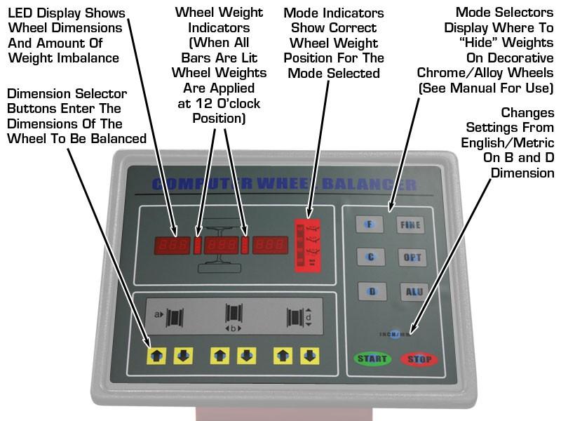
4 FIGURE 3


5 SETTING UP AUTOMATIC DATA ENTRY A. BEGIN BY CALIBRATING THE A MEASUREMENT (DISTANCE OF RIM FROM THE MACHINE) 1. PRESS AND HOLD THE STOP AND FINE KEYS AT THE SAME TIME. HOLD UNTIL THE LED S ON THE DISPLAY READ CAL P MOVE THE DISTANCE GAUGE (LOCATED ON THE FRONT RIGHT OF THE WHEEL BALANCER) TO THE 0 POSITION. 3. PRESS AND HOLD THE ALU KEY UNTIL THE LED S READ CAL P MOVE THE DISTANCE GAUGE TO THE 15 MARK. HOLD


6 THE GAUGE IN THIS POSITION. 5. PRESS AND HOLD THE ALU KEY UNTIL THE LED S READ RETURN THE DISTANCE GAUGE TO THE NORMAL, REST POSITION. THE A MEASUREMENT OF THE AUTOMATIC DATA ENTRY FEATURE IS NOW CALIBRATED. B. NOW CALIBRATE THE D MEASUREMENT (DIAMETER OF THE RIM) 1. PRESS AND HOLD THE STOP AND OPT KEYS UNTIL THE LED S READ CAL MOUNT A BARE 14 OR 15 INCH STEEL WHEEL ON THE BALANCER BEGIN BY SELECTING A CONE WHICH WILL FIT THE CENTER HOLE OF THE RIM. PLACE THE CONE ON THE SHAFT AND THEN THE WHEEL ON
7 THE SHAFT SO THAT THE WHEEL IS FIRMLY MOUNTED ON THE SHAFT. (SEE FIGURE 1) FINISH BY ATTACHING THE QUICK NUT TO THE SHAFT. OVERTIGHTING THE QUICK NUT WILL CAUSE DAMAGE 3. MANUALLY ENTER THE D MEASUREMENT OF THE WHEEL USING THE D OR D KEYS. 4. MOVE THE DISTANCE GAUGE SO THAT THE TIP TOUCHES THE RIM JUST UNDER THE EDGE. 5. PRESS AND HOLD THE ALU KEY UNTIL THE LED S READ RETURN THE DISTANCE GAUGE TO THE NORMAL, REST POSITION. THE D MEASUREMENT OF THE AUTOMATIC DATA ENTRY FEATURE IS NOW CALIBRATED. CALIBRATION A. MOUNT A 14 OR 15 INCH STEEL WHEEL ON THE BALANCER BEGIN BY SELECTING A CONE WHICH WILL FIT THE CENTER HOLE OF THE RIM. PLACE THE CONE ON THE SHAFT AND THEN THE WHEEL ON THE SHAFT SO THAT THE WHEEL IS FIRMLY MOUNTED ON THE SHAFT (SEE FIGURE 1). FINISH BY ATTACHING THE QUICK NUT TO THE SHAFT. OVERTIGHTING THE QUICK NUT WILL CAUSE DAMAGE
 B (WIDTH OF THE RIM) (THIS MEASUREMENT MUST BE ENTERED MANUALLY) D (DIAMETER OF")


8 B. USE THE AUTOMATIC DATA ENTRY FEATURE OR MANUALLY ENTER THE FOLLOWING (REFER TO FIGURE 2): A (DISTANCE OF RIM FROM THE MACHINE) B (WIDTH OF THE RIM) (THIS MEASUREMENT MUST BE ENTERED MANUALLY) D (DIAMETER OF RIM) ENTER SELF CALIBRATION MODE USING THE FOLLOWING STEPS 1. PRESS AND HOLD THE D & C KEYS AT THE SAME TIME. THE LED S ON THE DISPLAY WILL READ CAL CAL CAL AND WHEN THE LED S STOP FLASHING, RELEASE THE D & C KEYS. 2. CLOSE THE HOOD AND PRESS THE START KEY. (THE MACHINE WILL SPIN THROUGH A COMPLETE CYCLE FOR AROUND 20 SECONDS AND THEN COME TO A COMPLETE STOP.) THE DISPLAY WILL READ ADD 100 OR ADD 350 (100G = 3.5OZ)


9 3. NEXT, RAISE THE HOOD AND ATTACH THE CALIBRATION WEIGHT, 100 GRAM/3.5 OZ., WHICH COMES WITH THE MACHINE TO THE OUTSIDE OF THE RIM IN ANY POSITION. 4. CLOSE THE HOOD AND PRESS THE START KEY. (THE MACHINE WILL SPIN THROUGH ANOTHER COMPLETE CYCLE FOR AROUND 20 SECONDS AND THEN COME TO A COMPLETE STOP.) THE DISPLAY WILL READ End CAL CHECKING THE CALIBRATION 1. OPEN THE HOOD 2. CLOSE THE HOOD 3. PRESS START

10 THE BALANCER WILL SPIN THROUGH A NORMAL BALANCING CYCLE. WHEN THE BALANCER STOPS, IT SHOULD ASK FOR 100G/3.5OZ AT THE 12 O CLOCK POSITION ON THE WHEEL, WITH THE CALIBRATION WEIGHT AT THE 6 O CLOCK POSITION. REMOVE THE CALIBRATION WEIGHT (100 GRAM/3.5 OZ.) AND WHEEL. THE BALANCER IS NOW CALIBRATED AND READY FOR USE.
, B (WIDTH OF THE RIM) (THIS MEASUREMENT MUST BE ENTERED MANUALLY) D (DIAMETER OF RIM) 2.")

11 CONVERTING GRAMS - OUNCES 1. TURN THE WHEEL BALANCER ON AND MOUNT A WHEEL ONTO THE MACHINE. USING THE AUTOMATIC DATA ENTRY FEATURE OR MANUALLY ENTER THE FOLLOWING: A (DISTANCE OF RIM FROM THE MACHINE), B (WIDTH OF THE RIM) (THIS MEASUREMENT MUST BE ENTERED MANUALLY) D (DIAMETER OF RIM) 2. CLOSE THE HOOD AND THE MACHINE WILL SPIN THROUGH A CYCLE AND COME TO A COMPLETE STOP. OPEN THE HOOD AND THE DISPLAY WILL SHOW THE WEIGHT REQUIRED IN THE LED SCREEN. 3. THE FIRST TIME THIS IS DONE THE WEIGHT READING WILL BE IN GRAMS. TO CONVERT TO OUNCES: PUSH AND HOLD: THE STOP KEY AND BOTH THE A AND A MEASUREMENT KEY. THE KEYS MUST BE PUSHED SIMULTANEOUSLY. 4. YOU WILL KNOW THE WEIGHT SCALE HAS BEEN CHANGED TO OUNCES BY A DECIMAL POINT APPEARING IN THE LED UNTIL THE BALANCER IS UNPLUGGED, IT WILL REMAIN IN EITHER GRAMS OR OUNCES, DEPENDING ON YOUR PREFERENCE. BUTTON REFERENCE


12 Allows the user to switch between Dynamic and Static balancing modes. The balancer automatically rounds off the imbalance value to the nearest quarter ounce. This button allows the user to see the ACTUAL imbalance value of the wheel. The balancer is capable of isolating the heavy and light spots of the wheel/tire. Use this feature when the balancer is asking for more weight than you think the wheel should need. The balancer will instruct you on where to mark the tire and then the rim. You then will remove the wheel/tire assembly from the balancer, let out the air, and loosen the bead. Match up the mark that you made on the tire with the mark on the rim; now air up the tire and place the assembly back on the machine and run through a cycle. The amount of weight the balancer asks for should be considerably less than before. Allows you to scroll through the different alloy balancing options. You can use the more commonly used clip-on weights, or if you would like the weight to be hidden, you can opt to use adhesive weights. Use the ALU key to scroll through the different options and choose the one that best suits your needs. Pressing this key after a cycle has been completed will allow you to change previously entered dimensions and the balancer will re-calculate the weight reading without the need to run another cycle. Pressing this key by itself will run a diagnostic on the display led s, lighting each one up individually to show they are working. Also used in conjunction with the c key to enter calibration mode. This button changes the b (width of rim) and the d (diameter of rim) measurements from inches to millimeters.
Control Panel...3 Special Key Functions...4 Switching From Grams to Ounces...4 Calibration...5
 1 INDEX PAGE Control Panel...3 Special Key Functions...4 Switching From Grams to Ounces...4 Calibration...5 2 Function Press to switch between static and dynamic balancing modes. Aluminum Mode Press to
Control Panel...3 Special Key Functions...4 Switching From Grams to Ounces...4 Calibration...5 Automatic Gauge Calibration...11
 INDEX PAGE Control Panel...3 Special Key Functions...4 Switching From Grams to Ounces...4 Calibration...5 Automatic Gauge Calibration...11 2 Function Press to switch between static and dynamic balancing
NTB-550 Manual. Contents
 1 NTB-550 Manual Please read this Manual before using the Machine. You will need to know the safety instructions, System Settings, Wheel Parameters Input and Calibration process before you can properly
NTB-800 Manual. Contents
 NTB-800 Manual Please read this Manual before using the Machine. You will need to know the safety instructions, System Settings, Wheel Parameters Input and Calibration process before you can properly balance
**Detailed instructions for balancing aluminum wheels in Section 15 of manual.
 PWB-1530 Manual Please read this Manual before using the Machine. You will need to know the safety instructions, System Settings, Wheel Parameters Input and Calibration process before you can properly
 VOLUME 2.0 2 This page intentionally left blank JWB 100 Operator s Manual page 3 Table of Contents 1 Summary 1.1 Features 4 1.2 Specifications 4 2 Installation 2.1 Installation 5 3 Structure 3.1 Main Structure
DSP Wheel Balancer
 Form 3584T, 02-96 Supersedes Form 3584T, 06-95 OPERATION INSTRUCTIONS DSP9000-9500 Wheel Balancer Copyright 1994-1996 Hunter Engineering Company OWNER INFORMATION Model Number Serial Number Date Installed
Wheel Balancer Manual(A)
") Wheel Balancer Manual(A) Contents 1.General ----------------------------------------------------------------------------------------------------------------------------------2 2.Machine assembly------------------------------------------------------------------------------------------------------------------------2
Wheel Balancer Manual(A) Contents 1.General ----------------------------------------------------------------------------------------------------------------------------------2 2.Machine assembly------------------------------------------------------------------------------------------------------------------------2
GLO-1060 (WHEEL BALANCER)
") GLO-1060 (WHEEL BALANCER) OPERATION MANUAL DATE INSTALLED: SERIAL # MANUFACTURING DATE: (EAGLE - GLOBAL : UNITE) -1- GLO-1060 WHEEL BALANCER -2- INDEX 1- Introduction ---------------------------------------------------------------------------------Page
GLO-1060 (WHEEL BALANCER) OPERATION MANUAL DATE INSTALLED: SERIAL # MANUFACTURING DATE: (EAGLE - GLOBAL : UNITE) -1- GLO-1060 WHEEL BALANCER -2- INDEX 1- Introduction ---------------------------------------------------------------------------------Page
INSTALLATION, OPERATION, MAINTENANCE MANUAL KEEP THE MANUAL NEAR THE MACHINE ALL TIME AND MAKE SURE ALL USERS HAVE READ THIS WHEEL BALANCER
 INSTALLATION, OPERATION, MAINTENANCE MANUAL KEEP THE MANUAL NEAR THE MACHINE ALL TIME AND MAKE SURE ALL USERS HAVE READ THIS WHEEL BALANCER FOLLOW THE INSTRUCTIONS CAREFULLY TO GRANT THE MACHINE A CORRECT
K&L MC200 ELITE WHEEL BALANCER Product Manual - MC Wheel Balancing
 Product Manual - MC Wheel Balancing Thank you for purchasing this K&L Product. Please inspect this unit for damage prior to use. This manual will review balancing a motorcycle wheel. Please read the entire
WHEEL BALANCERS FOR BALANCING AUTOMOBILE, & LIGHT TRUCK TIRES / WHEELS
 PLEASE READ THE ENTIRE CONTENTS OF THIS MANUAL PRIOR TO INSTALLATION AND OPERATION. BY PROCEEDING YOU AGREE THAT YOU FULLY UNDERSTAND AND COMPREHEND THE FULL CONTENTS OF THIS MANUAL. FORWARD THIS MANUAL
SAFETY INFORMATION. For your safety, read this manual thoroughly before operating the EEWB300A Wheel Balancer
 SAFETY INFORMATION For your safety, read this manual thoroughly before operating the EEWB300A Wheel Balancer The Model EEWB300A Wheel Balancer is intended for use by properly trained automotive technicians.
Wheel Products. WP8300 Operators Manual Rev: 910
 Wheel Products by WP8300 Operators Manual Rev: 910 Table of Contents Warranty Page 1 1. General Page 2 General Safety Regulations Page 2 Field of Application Page 2 Overall Dimensions Page 2 Technical
Instructions for use CONTENTS
 Instructions for use I CONTENTS 1 - GENERAL 3 1.1 - GENERAL SAFETY REGULATIONS 3 1.1.1 - STANDARD SAFETY DEVICES 3 1.2 - FIELD OF APPLICATION 3 1.3 - OVERALL DIMENSIONS (standard guard) 3 1.4 - TECHNICAL
Model 8.6 and Model 8.7 High Performance Wheel Balancer Operation Instructions FORM #5608
 â 7 Model 8.6 and Model 8.7 High Performance Wheel Balancer Operation Instructions FORM #5608 (BLANK PAGE) Page 2 â John Bean Company 309 Exchange Avenue Conway, AR 72032 USA Phone (501) 450-1500 Fax (501)
180 PRO3DAUTO 3DTECHNOLOGY EQUIPPED WITH AUTOMATIC WHEEL DIMENSION SONAR AND LASER RIM PROFILE SCANNER ELECTRONIC WHEEL BALANCERS WITH MICROPROCESSOR
 WHEEL BALANCERS 180 PRO3DAUTO EQUIPPED WITH AUTOMATIC WHEEL DIMENSION SONAR AND LASER RIM PROFILE SCANNER 3DTECHNOLOGY ELECTRONIC WHEEL BALANCERS WITH MICROPROCESSOR AUTOMATIC BALANCING MODE Perfect balancing
WHEEL BALANCER INSTRUCTION MANUAL DWC ATTENTION
 WHEEL BALANCER INSTRUCTION MANUAL DWC ATTENTION This manual is an integral part of the product. The warnings and instructions in this manual provide important information about SAFETY IN USE and MAINTENANCE
INSTALLATION, OPERATION AND MAINTENANCE MANUAL
 TW F - 150 Wheel balancing machine INSTALLATION, OPERATION AND MAINTENANCE MANUAL Read this entire manual carefully before installation or operation of the TW F-150. Follow the instructions strictly. 1
ELECTRONIC WHEEL BALANCER
 ELECTRONIC WHEEL BALANCER Model 47211 Assembly And Operation Instructions Due to continuing improvements, actual product may differ slightly from the product described herein. 3491 Mission Oaks Blvd.,
2 - HANDLING, HOISTING START-UP...4
 Instructions for use I INDEX Page 1 - GENERAL...3 1.1 - GENERAL SAFETY REGULATIONS...3 1.1.1 - STANDARD SAFETY DEVICES...3 1.2 - FIELD OF APPLICATION...3 1.3 - OVERALL DIMENSIONS (standard protection)...3
EEWB330A HANDSPIN WHEEL BALANCER
 EEWB330A HANDSPIN WHEEL BALANCER For: PASSENGER CARS AND LIGHT TRUCK WHEELS Operating Instructions Form ZEE330A Rev C SAFETY INFORMATION For your safety, read this manual thoroughly before operating the
WHEEL AND TIRE GROUP CONTENTS WHEEL AND TIRE DIAGNOSIS WHEEL AND TIRE SPECIFICATIONS ON-VEHICLE SERVICE...
 31-1 GROUP 31 CONTENTS.... 31-2 DIAGNOSIS........................ 31-2 WHEEL BALANCE ACCURACY........ 31-3 ON-VEHICLE SERVICE........... 31-7 TIRE INFLATION PRESSURE CHECK... 31-7 TIRE WEAR CHECK..................
VAS 6230B Road Force Touch. Customized for All Audi, Bently, Seat, Skoda and Volkswagen Vehicles NEW!
 VAS 6230B Road Force Touch Customized for All Audi, Bently, Seat, Skoda and Volkswagen Vehicles VAS 6230B at a glance ow With More Speed!* 3 Perform a Road Force test and balance faster than a traditional
EEWB308A COMPUTER HAND SPIN MOTORCYCLE WHEEL BALANCER
 EEWB308A COMPUTER HAND SPIN MOTORCYCLE WHEEL BALANCER FOR: MOTORCYCLE WHEELS OPERATION INSTRUCTIONS Form ZEEWB308A SAFETY INFORMATION For your safety, read this manual thoroughly before operating the
XR The Ultimate in Balancing Performance
 VERSATILITY SPEED SPEED Coats wheel balancers are used in applications ranging from small one-bay shops to high-volume garages.they're fast, accurate, and profitable to own. SPECIALTY The Advantage of
geodyna 2600 Hofmann Werkstatt-Technik
 geodyna 2600 Operation manual Car wheel balancer Hofmann Werkstatt-Technik Contents Safety rules and function Contents Page. Safety rules and function... 2 2. Installation of the machine... 5 3. Electrical
TABLE OF CONTENTS 1 - GENERAL...3
 Instructions for use I TABLE OF CONTENTS Page 1 - GENERAL...3 1.1 - GENERAL SAFETY REGULATIONS...3 1.1.1 - STANDARD SAFETY DEVICES...3 1.2 - FIELD OF APPLICATION...3 1.3 - OVERALL DIMENSIONS...3 1.4- TECHNICAL
INSTALLATION AND OPERATION MANUAL
 INSTALLATION AND OPERATION MANUAL MODEL: DST-2420 WHEEL BALANCER PLEASE READ THE ENTIRE CONTENTS OF THIS MANUAL PRIOR TO INSTALLATION AND OPERATION. BY PROCEEDING YOU AGREE THAT YOU FULLY UNDERSTAND AND
WHEEL AND TIRE GROUP CONTENTS WHEEL AND TIRE DIAGNOSIS WHEEL AND TIRE SPECIFICATIONS ON-VEHICLE SERVICE...
 31-1 GROUP 31 CONTENTS DIAGNOSIS.... 31-2 DIAGNOSIS........................ 31-2 WHEEL BALANCE ACCURACY........ 31-3 ON-VEHICLE SERVICE........... 31-6 TIRE INFLATION PRESSURE CHECK... 31-6 TIRE WEAR CHECK..................
Installation and Operation Manual
 1645 Lemonwood Dr. Santa Paula, CA 93060 USA Toll Free: (800) 253-2363 Tel: (805) 933-9970 rangerproducts.com Laser-Spot Wheel Balancer Installation and Operation Manual Manual P/N 5900086 Manual Revision
EEWB304C COMPUTER WHEEL BALANCER
 EEWB304C COMPUTER WHEEL BALANCER FOR: PASSENGER CAR & LIGHT TRUCK WHEELS OPERATION INSTRUCTIONS Form ZEEWB304C SAFETY INFORMATION For your safety, read this manual thoroughly before operating the Model
NOTE: THESE PROCEDURES ARE THE SAME AS BEING IN THE SERVICE MODE. NOTE: ONCE THE UNIT IS POWERED DOWN THE VALUES FOR C4 WILL BE GONE.
 SERVICE CODES There are only two service codes that are accessible in a Users Mode. These are C4 (Unbalance Compensation) and C12 (Display Counter Indication). To access these service code in Users Mode
Vero Series Wheel Balancer Models V200 2D/3D Wheel Balancers
 Vero Series Wheel Balancer Models V200 2D/3D Wheel Balancers See Balancing Your First Tire on page 3. Shown with optional accessories. Safety Instructions Set-up Instructions Operation Instructions Maintenance
WHEEL AND TIRE GROUP CONTENTS GENERAL SPECIFICATIONS SERVICE SPECIFICATIONS WHEEL AND TIRE
 31-1 GROUP 31 CONTENTS GENERAL SPECIFICATIONS...... 31-2 SERVICE SPECIFICATIONS....... 31-2 DIAGNOSIS.... 31-3 DIAGNOSIS........................ 31-3 WHEEL BALANCE ACCURACY........ 31-4 ON-VEHICLE SERVICE...........
FOR: PASSENGER CAR & LIGHT TRUCK WHEELS COMPUTER WHEEL BALANCER VPI SYSTEM I OPERATION INSTRUCTIONS. Form ZEEWB504D
 FOR: PASSENGER CAR & LIGHT TRUCK WHEELS VPI SYSTEM I COMPUTER WHEEL BALANCER OPERATION INSTRUCTIONS Form ZEEWB504D Rev 11/16/2010 SAFETY INFORMATION For your safety, read this manual thoroughly before
WHEEL BALANCERS & TYRE CHANGERS QUALITY YOU EXPECT AT A PRICE YOU WOULDN T THE STANDARD IN INFORMATION, EQUIPMENT AND DIAGNOSTICS SYSTEMS
 QUALITY YOU EXPECT AT A PRICE YOU WOULDN T THE STANDARD IN INFORMATION, EQUIPMENT AND DIAGNOSTICS SYSTEMS http://diagnostics.snapon.co.uk INTRODUCTION TYRE AND WHEEL BROCHURE The Sun range of Tyre Changers
Models 1100, D Wheel Balancers
 Models 1100, 1150-2D Wheel Balancers See Balancing Your First Tire on page 4. Model 1150-2D Shown Safety Instructions Set-up Instructions Operation Instructions Maintenance Instructions READ these instructions
2 Table of Contents Chapter Contents 1 Safety instructions 2 General descriptions 2.1 Standard accessories 2.2 Optional accessories 3 Technical specif
 1 Operation Manual C388G Wheel Balancer Read these instructions before placing unit in service. Keep these and other materials with the unit in a binder near the machine for easy reference by supervisors
GSP9200. High-Capacity Balancer with Unmatched Features
 GSP9200 High-Capacity Balancer with Unmatched Features GSP9200 balancer at a glance SmartWeight SmartWeight Balancing Technology 4 Maximizes productivity 4 Improves balance 4 Minimizes weight usage Bottom-Dead-Center
ProRide Diagnostic ProRide Diagnostic PL Wheel Balancer Models
 ProRide Diagnostic ProRide Diagnostic PL Wheel Balancer Models See Balancing Your First Tire on page 5. Safety Instructions Set-up Instructions Operation Instructions Maintenance Instructions READ these
Models CB6 Series (CB66-VE)
") Models CB6 Series (CB66-VE) 1. CONTROL PANEL The machine control panel is shown in Figure F1. The control panel allows the operator to give commands and enter or modify data. The same control panel displays
Models CB6 Series (CB66-VE) 1. CONTROL PANEL The machine control panel is shown in Figure F1. The control panel allows the operator to give commands and enter or modify data. The same control panel displays
V8 XJ Series/XK. Vibration/Shimmy Tire Radial Force Variation Optimizing Wheels And Tires
 SERVICE V8 XJ Series/XK DATE 04/02 Amended 04/03 TECHNICAL BULLETIN Vibration/Shimmy Tire Radial Force Variation Optimizing Wheels And Tires Remove and destroy Bulletin 204-17, dated 4/02. Replace with
SCION iq ALLOY WHEEL Preparation. Part Number: PT NOTE: Part number of this accessory may not be the same as the part number shown.
 Preparation Part Number: PT904-74100 NOTE: Part number of this accessory may not be the same as the part number shown. Kit Contents 1 1 16" Alloy Wheel 2 1 Center Cap 3 1 Hardware Bag 4 1 Care Card Hardware
WHEEL AND TYRE GROUP CONTENTS WHEEL AND TYRE DIAGNOSIS WHEEL AND TYRE SPECIFICATIONS ON-VEHICLE SERVICE...
 31-1 GROUP 31 WHEEL AND TYRE CONTENTS... 31-2 DIAGNOSIS........................ 31-2 WHEEL BALANCE ACCURACY........ 31-3 ON-VEHICLE SERVICE........... 31-7 TYRE INFLATION PRESSURE CHECK.. 31-7 TYRE WEAR
INSTRUCTION & MAINTENANCE MANUAL. Read this entire manual carefully before installation or operation of the TW F-95. Follow the instructions strictly.
 TW F-95 Wheel balancing machine INSTRUCTION & MAINTENANCE MANUAL Read this entire manual carefully before installation or operation of the TW F-95. Follow the instructions strictly. I II CATALOGUE V2016.08
geodyna 9300/9300p Operation instructions Wheel balancer Form ZEEWB731A 9300P SHOWN
 geodyna 9300/9300p Operation instructions Wheel balancer 9300P SHOWN Form ZEEWB731A SAFETY INFORMATION For your safety, read this manual thoroughly before operating the 9300/9300P Wheel Balancer The Hofmann
ForceMatch HD The world's #1 heavy-duty diagnostic balancer
 ForceMatch HD The world's #1 heavy-duty diagnostic balancer The ForceMatch HD Balancer ForceMatch HD balancer quickly measures runout with every balance Roller contacts wheel surface Load Roller Roller
Truck Wheel Balancer OPERATION GUIDE. Model 6200HS FORM Z6200HS
 Truck Wheel Balancer Model 6200HS OPERATION GUIDE FORM Z6200HS Operation Guide CONTENTS Safety Cautions and Warnings...ii Installation... iii Unpacking... iii Assembly... iii Setup...iv Weight Increment
EEWB305C COMPUTER WHEEL BALANCER
 EEWB305C COMPUTER WHEEL BALANCER FOR: PASSENGER CAR & LIGHT TRUCK WHEELS OPERATION INSTRUCTIONS Form ZEEWB305C SAFETY INFORMATION For your safety, read this manual thoroughly before operating the Model
950 Pro Racer WHEEL BALANCER. Installation Instructions Operating Instructions Safety Instructions Maintenance Instructions
 950 Pro Racer WHEEL BALANCER Installation Instructions Operating Instructions Safety Instructions Maintenance Instructions READ these instructions before placing unit in service KEEP these and other materials
Silverline. S210 Operators Manual Rev: 211
 Silverline by S210 Operators Manual Rev: 211 Table of Contents Machine Warranty Page 1 Safety Instructions Pages 2 4 Installation Pages 5 Technical Features Pages 5 Transportation and Installation Pages
VAS 6230A Road Force Measurement Specifications *
 VAS 6230A Road Force Measurement Specifications * Power Requirements: Air Supply Requirements: Motor: Shipping Weight: Copyright 2007, Hunter Engineering Company 230 V (+10% -15%), 10 amp, 50/60 Hz, 1-ph
CATALOGUE 1. Introduction Specification and Features Specification Features Working Environment
 CATALOGUE 1. Introduction... 3 2. Specification and Features... 3 2.1 Specification... 3 2.2 Features... 3 2.3 Working Environment... 4 3. The Constitution of Dynamic Balancer... 4 3.1 Machine... 4 3.2
COMPUTER WHEEL BALANCER EEWB526B. BFH 800b. Operator s Manual
 COMPUTER WHEEL BALANCER BFH 800b EEWB526B Operator s Manual ZEEWB526B April 15, 2007 SAFETY INFORMATION For your safety, read this manual thoroughly before operating the BFH 800 Wheel Balancer The JBC
GSP9700 Series Road Force Measurement System
 OPERATION INSTRUCTIONS Form 4202T, 11-05 Supersedes Form 4202T, 07-05 GSP9700 Series Road Force Measurement System With SmartWeight Balancing Technology Software Version 5.0 Copyright 1997-2005 Hunter
M ALU-S
 CATALOGUE 1. Introduction...1 2. Specification and Features...1 2.1 Specification... 1 2.2 Features... 1 2.3 Working Environment... 1 3. The Constitution of Dynamic Balancer...1 3.1 Machine... 1 3.2 Electricity
GSP9200 Lite Series Computerized LCD Balancer (GSP9220) With SmartWeight Balancing Technology Software Version 3.3
 With SmartWeight Balancing Technology Software Version 3.3") OPERATION INSTRUCTIONS Form 6618TE-05, 06-13 GSP9200 Lite Series Computerized LCD Balancer (GSP9220) With SmartWeight Balancing Technology Software Version 3.3 Copyright 2006-2013 Hunter Engineering Company
OPERATION INSTRUCTIONS Form 6618TE-05, 06-13 GSP9200 Lite Series Computerized LCD Balancer (GSP9220) With SmartWeight Balancing Technology Software Version 3.3 Copyright 2006-2013 Hunter Engineering Company
Wheel Balancer Models D, D, D
 Wheel Balancer Models 1400 2D, 1500 3D, 1600 3D Model 1400 Shown Model 1500 Shown Model 1600 Shown See Balancing Your First Tire on page 7. Safety Instructions Set Up Instructions Operation Instructions
GSP9700 Road Force. The World s #1 Diagnostic Balancer. Featuring. SmartWeight Balancing Technology
 GSP9700 Road Force The World s #1 Diagnostic Balancer Featuring SmartWeight Balancing Technology The Hunter GSP9700 goes far beyond traditional functions SmartWeight Odometer tracks savings Minimizes weight
4300SC Balancer Service Manual
 Match-Balance Series 4300SC Balancer Service Manual Form 5047-1 Page Section TABLE OF CONTENTS Subject 4 5 6 7 8 9 10 11 12 13 14 15 16 1.0 2.0 3.0 3.1 3.2 3.3 3.4 3.5 3.6 4.0 5.0 5.1 5.2 5.3 5.4 5.5 5.6
New car Wheel Balancers for car, van and motorcycle wheel
 The MONDOLFO FERRO balancer range has been improved with the new model, presented to the public for the first time during Autopromotec and available for sale already since September. 32 The new completed
TOYOTA Runner (17 Beadlock ) ALLOY WHEEL Preparation
 ALLOY WHEEL Preparation") Preparation Part Number: PTR45-35010 Kit Contents Item # Quantity Reqd. Description 1 1 Forged Al Wheel 17 x7.5 x 6mm Hardware Bag Contents Item # Quantity Reqd. Description 1 1 per wheel TRD Center Cap
Preparation Part Number: PTR45-35010 Kit Contents Item # Quantity Reqd. Description 1 1 Forged Al Wheel 17 x7.5 x 6mm Hardware Bag Contents Item # Quantity Reqd. Description 1 1 per wheel TRD Center Cap
1175 Wheel Balancer. Installation Instructions Operating Instructions Safety Instructions Maintenance Instructions
 1175 Wheel Balancer See Balancing Your First Tire on page 1. Installation Instructions Operating Instructions Safety Instructions Maintenance Instructions READ these instructions before placing unit in
GSP97MB Road Force Touch. Customized for Mercedes Benz Vehicles NEW!
 GSP97MB Road Force Touch Customized for Mercedes Benz Vehicles GSP97MB at a glance Now With More Speed!* Perform a Road Force test and balance faster than a traditional balancer! Touchscreen Interface
ALL-IN-ONE Tyre Changer & Wheel Balancer
 ALL-IN-ONE Tyre Changer & Wheel Balancer 1. As shown in figure, assemble the base plate (1) and the bracket (2) with three pieces M10 bolts, and then fixed the base plate (1) on the tyre changer (3) with
# B: Mounting, Balancing and Installation of Accessory Wheels and Tires Available Through GM Accessories - (Feb 11, 2015)
") Page 1 of 8 Document ID: 4072388 #08-03-10-004B: Mounting, Balancing and Installation of Accessory Wheels and Tires Available Through GM Accessories - (Feb 11, 2015) Subject: Mounting, Balancing and Installation
Page 1 of 8 Document ID: 4072388 #08-03-10-004B: Mounting, Balancing and Installation of Accessory Wheels and Tires Available Through GM Accessories - (Feb 11, 2015) Subject: Mounting, Balancing and Installation
775/875 Wheel Balancer
 775/875 Wheel Balancer See Balancing Your First Tire on page 1. Installation Instructions Operating Instructions Safety Instructions Maintenance Instructions READ these instructions before placing unit
Semi-Automatic Wheel Balancer
 INSTRUCTIONS FOR Semi-Automatic Wheel Balancer Stock No.81646 Part No.WB100 IMPORTANT: PLEASE READ THESE INSTRUCTIONS CAREFULLY TO ENSURE THE SAFE AND EFFECTIVE USE OF THIS PRODUCT. GENERAL INFORMATION
SmartWeight Touch High-capacity balancer with unmatched features
 SmartWeight Touch High-capacity balancer with unmatched features Key features at a glance SmartWeight technology Improves balance Minimizes weight usage Maximizes productivity STANDARD Touchscreen interface
VIBRATIONS TIRE AND WHEEL WHEEL AND TIRE ASSEMBLIES VIBRATION ISOLATING WHEEL AND TIRE VIBRATIONS
 TIRE AND WHEEL VIBRATIONS In this article, we will review some basics about tracking down and troubleshooting tire and wheel related vibration behavior. It also includes some tips and repair techniques
GSP9200 Series Computerized LCD Balancer
 OPERATION INSTRUCTIONS Form 5393-T, 11-08 Supersedes Form 5393T, 09-08 GSP9200 Series Computerized LCD Balancer With SmartWeight Balancing Technology Software Version 2.6 Copyright 2006-2008 Hunter Engineering
SmartWeight Touch. High-Capacity Balancer with Unmatched Features
 SmartWeight Touch High-Capacity Balancer with Unmatched Features SmartWeight Touch balancer at a glance SmartWeight Technology SmartWeight Balancing Technology 3 Improves balance 3 Minimizes weight usage
TOYOTA TUNDRA ALLOY WHEEL Preparation. Part Number: PT
 Preparation Part Number: PT758-34090 Kit Contents Item # Quantity Reqd. Description 1 1 Alloy Wheel 2 3 4 Hardware Bag Contents Item # Quantity Reqd. Description 1 1 Center Cap (PT385-34090-CC) NOTE: Part
GSP9200 Series Computerized LCD Balancer
 OPERATION INSTRUCTIONS Form 5393-T, 02-10 Supersedes Form 5393-T, 11-08 GSP9200 Series Computerized LCD Balancer (GSP9220) With SmartWeight Balancing Technology Software Version 3.1 Copyright 2006-2010
6275HS Wheel Balancer
 6275HS Wheel Balancer Installation Instructions Operating Instructions Safety Instructions Maintenance Instructions READ these instructions before placing unit in service KEEP these and other materials
Wheel Balancers. Safety Instructions Set Up Instructions Operation Instructions Maintenance Instructions
 Wheel Balancers See Balancing Your First Tire on page 7. Model 350 Shown Safety Instructions Set Up Instructions Operation Instructions Maintenance Instructions Model 550 Shown READ these instructions
VAS 6230B Road Force Touch. Customized for All Audi and Volkswagen Vehicles NEW!
 VAS 620B Road Force Touch Customized for All Audi and Volkswagen Vehicles VAS 620B at a glance Now With More Speed!* Perform a Road Force test and balance faster than a traditional balancer! Touchscreen
Model 1850 Wheel Balancer
 Model 1850 Wheel Balancer Instructions for use I INDEX page 1 - GENERAL...3 1.1 - GENERAL SAFETY REGULATIONS...3 1.1.1 - STANDARD SAFETY DEVICES...3 1.2 - FIELD OF APPLICATION...3 1.3 - OVERALL DIMENSIONS...3
Sequoia power steering rack service Match-mounting wheels and tires Oxygen sensor circuit diagnosis
 In this issue: Sequoia power steering rack service Match-mounting wheels and tires Oxygen sensor circuit diagnosis PHASE MATCHING Often referred to as match mounting, phase matching involves mounting the
User and Fitting Manual June 2008
 User and Fitting Manual June 2008 Electric Curtain Track System Silent Gliss 5090 User and fitting Manual Silent Gliss 5090 Page Copyright June 2008 by Silent Gliss International Ltd., 3073 Gümligen/Berne
SmartWeight Touch. High-Capacity Balancer with Unmatched Features NEW!
 SmartWeight Touch High-Capacity Balancer with Unmatched Features SmartWeight Touch balancer at a glance SmartWeight Technology SmartWeight Balancing Technology Improves balance Minimizes weight usage Maximizes
6401 Computer. Truck Wheel Balancer. Installation Instructions Operating Instructions Safety Instructions Maintenance Instructions
 6401 Computer Truck Wheel Balancer Installation Instructions Operating Instructions Safety Instructions Maintenance Instructions READ these instructions before placing unit in service KEEP these and other
WS INSTRUCTION MANUAL TRUCK AND CAR WHEEL BALANCER
 TRUCK AND CAR WHEEL BALANCER WS 00 INSTRUCTION MANUAL F Automotive Resources, Inc. Coppermine Drive Manassas, VA 00 (00) -0 Web Site: http://www.ari-hetra.com E-Mail: webmaster@ari-hetra.com INDEX Automotive
2006 MINI Cooper SUSPENSION Wheels & Tires - Repair Instructions - Cooper (1.6L) R50/W10 & Cooper S
 R50/W10 & Cooper S") WHEELS 2002-05 SUSPENSION Wheels & Tires - Repair Instructions - Cooper (1.6L) R50/W10 & Cooper S 36 10 300 REMOVING OR INSTALLING FRONT OR REAR WHEEL NOTE: For Special Tool identification, see WHEEL AND
WHEELS 2002-05 SUSPENSION Wheels & Tires - Repair Instructions - Cooper (1.6L) R50/W10 & Cooper S 36 10 300 REMOVING OR INSTALLING FRONT OR REAR WHEEL NOTE: For Special Tool identification, see WHEEL AND
ALLOY WHEEL. Installation Instructions PLEASE READ ALL INSTRUCTIONS BEFORE INSTALLING WHEELS
 ALLOY Installation Instructions PLEASE READ ALL INSTRUCTIONS BEFORE INSTALLING S Failure to comply with these instructions can cause serious injury or death to the installer or occupants of the vehicle.
INSTALLATION, OPERATION, MAINTENANCE MANUAL KEEP THE MANUAL NEAR THE MACHINE ALL TIME AND MAKE SURE ALL USERS HAVE REAP THIS WHEEL BALANCER
 INSTALLATION, OPERATION, MAINTENANCE MANUAL KEEP THE MANUAL NEAR THE MACHINE ALL TIME AND MAKE SURE ALL USERS HAVE REAP THIS WHEEL BALANCER... FOLLOW THE INSTRUCTIONS CAREFULLY TO GRANT THE MACHINE A CORRECT
LEXUS IS 250/350 Sedan (RWD Only) IS 250/350Convertible Preparation
 IS 250/350Convertible Preparation") Preparation Part Number: 08457-30813(Mesh type Fr) 08457-53811(Mesh type Rr) PT533-53060(Spoke type Fr) PT533-53061(Spoke type Rr) Kit Contents Item # Quantity Reqd. Description 1a 1 Alloy Wheel mesh type
Preparation Part Number: 08457-30813(Mesh type Fr) 08457-53811(Mesh type Rr) PT533-53060(Spoke type Fr) PT533-53061(Spoke type Rr) Kit Contents Item # Quantity Reqd. Description 1a 1 Alloy Wheel mesh type
ALLOY WHEEL. Installation Instructions PLEASE READ ALL INSTRUCTIONS BEFORE INSTALLING WHEELS
 ALLOY Installation Instructions PLEASE READ ALL INSTRUCTIONS BEFORE INSTALLING S Failure to comply with these instructions can cause serious injury or death to the installer or occupants of the vehicle.
TOYOTA 2011+Tacoma TX Package (16 Beadlock ) Preparation TRD Technical Support
 Preparation TRD Technical Support") Preparation TRD Technical Support 1-800-688-5912 Part Number: PTR18-35090 Black Kit Contents Item # Quantity Reqd. Description 1 1 Cast Al Wheel 16 x7.5 x10mm Hardware Bag Contents Item # Quantity Reqd.
Preparation TRD Technical Support 1-800-688-5912 Part Number: PTR18-35090 Black Kit Contents Item # Quantity Reqd. Description 1 1 Cast Al Wheel 16 x7.5 x10mm Hardware Bag Contents Item # Quantity Reqd.
WHEEL BALANCER WITH MICROPROCESSOR FOR CARS, LIGHT COMMERCIAL VEHICLES AND MOTORCYCLES ( Series A )
") 0052-1 HofmannIndustrial GmbH A - 5302 Henndorf Hauptstraße 59 Tel +43-6214-6466-12 \ Fax -20 WHEEL BALANCER WITH MICROPROCESSOR FOR CARS, LIGHT COMMERCIAL VEHICLES AND MOTORCYCLES ( Series A ) Nr. 0052-1998.10
0052-1 HofmannIndustrial GmbH A - 5302 Henndorf Hauptstraße 59 Tel +43-6214-6466-12 \ Fax -20 WHEEL BALANCER WITH MICROPROCESSOR FOR CARS, LIGHT COMMERCIAL VEHICLES AND MOTORCYCLES ( Series A ) Nr. 0052-1998.10
# C: Revised Wheel Balancer Mounting Instructions (Heavy Duty Models Only) - (Oct 10, 2014)
 - (Oct 10, 2014)") Page 1 of 15 Document ID: 3994174 #10-03-10-001C: Revised Wheel Balancer Mounting Instructions (Heavy Duty Models Only) - (Oct 10, 2014) Subject: Revised Wheel Balancer Mounting Instructions (Heavy Duty
Page 1 of 15 Document ID: 3994174 #10-03-10-001C: Revised Wheel Balancer Mounting Instructions (Heavy Duty Models Only) - (Oct 10, 2014) Subject: Revised Wheel Balancer Mounting Instructions (Heavy Duty
Motorcycle Kit Quick Start Guide
 Motorcycle Kit Quick Start Guide This guide describes the basic set-up procedures for the Atlas MC Kit and MCXLT Kit. Motorcycle wheels vary greatly in size, design, and shape. Because of these many differences,
BALATRON 221/212 USER S MANUAL For any information, please contact:
 BALATRON / USER S MANUAL FIG. Balatron FIG. Balatron For any information, please contact: e-mail: www.fasep.it info@fasep.it FASEP 000 srl Via Faentina 96 50030 Ronta (Fi) Italy Tel. #39 055 840 36 Fax
WHEEL AND TYRE GROUP 31 CONTENTS ON-VEHICLE SERVICE GENERAL INFORMATION SERVICE SPECIFICATIONS TROUBLESHOOTING...
 GROUP 31 CONTENTS GENERAL INFORMATION........ 31-2 SERVICE SPECIFICATIONS....... 31-2............ 31-3 DIAGNOSIS........................ 31-3 WHEEL BALANCE ACCURACY........ 31-4 ON-VEHICLE SERVICE...........
Computerscales DX Model Operating Instructions
 16892 146 th St SE, Monroe, WA 98272 (360) 453-2030 Computerscales DX Model 72641 Operating Instructions QUICK START INSTRUCTIONS: 1) Set up pads alongside kart (they are interchangeable). 2) Connect cables
TOYOTA 4RUNNER ALLOY WHEEL FJ CRUISER Preparation
 Preparation Part Number: PTR20-35110-BK (Matte Black) PTR20-35110-GR (Graphite Grey) Kit Contents Item # Quantity Reqd. Description 1 4 for 4Runner 5 for FJ Cruiser 17 x 7.0 x 4 mm 6-Spoke Painted Alloy
CHAPTER 3 CHECKOUT, CALIBRATION AND MAINTENANCE
 CHAPTER 3 CHECKOUT, CALIBRATION AND MAINTENANCE GENERAL This Chapter incorporates all motorized Y2k balancers manufactured in Conway Arkansas. The test codes for each digital display balancer are alike,
INSTALLATION GUIDE Multi-Gauge Set with sending units Part Number: M 9999
 Made in America Lifetime Guarantee Thank you for purchasing this instrument set from Intellitronix. We value our customers! INSTALLATION GUIDE Multi-Gauge Set with sending units Part Number: M 9999 * Always