Digital Controller 12 volt only
|
|
|
- Beverly Bryant
- 5 years ago
- Views:
Transcription

.")
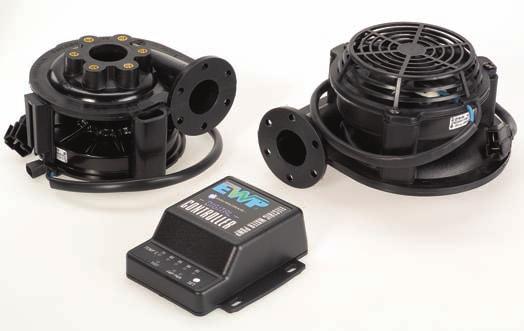
1 Digital Controller 12 volt only Part #8020 For optimum control of Electric Water Pumps. Suits Davies, Craig EWP 80, EWP 115, EBP and Thermatic Fans. The updated Digital Controller now has two specific functions. This unique Digital Controller will manage the operation of the EWP by varying the speed of the pump in response to the coolant temperature and manage control of your electric engine fan. The Controller has a push-button on the facia panel that offers five target temperatures: 75 C, 80 C, 85 C, 90 C and 95 C (165, 175, 185, 195 and 205 F). Generally, higher engine temperature will offer improved fuel efficiency and lower engine temperature more power. The Digital Controller will operate the engine s electric fan automatically once the engine has reached 3 C (5.4 F) above the targeted (set) temperature. Another significant benefit is that the Controller allows the EWP to run on after ignition shutdown to eliminate heat soak. Technical specifications Input voltage 12V DC to 15V DC Output voltage 5V to 15V Maximum current 12A Operating temperatures -20 to 60 C (-5 to 140 F) Digital Controller operation Targeted (set) temperatures 75 C, 80 C, 85 C, 90 C and 95 C (165, 175, 185, 195 and 205 F) Fan cut-in temperature Controller type 3 C (5.4 F) above the targeted (set) temperature PCB with micro-processor 8 TO SYSTEM VOLTAGE FAN ON Sensor type Thermister in housing Time-out 2 minutes maximum or set -5 C (23 F) Indicator LEDs Temperature, power, EWP, test, fan Weight Dimensions 90 grams (3.2 oz) 101mm (l) x 95mm (w) x 35mm (d) AMBIENT (+3º ABOVE SET POINT, FAN ACTIVATES) +3 TARGET (SET POINT) Kit contents Dimensions Part # Description Qty 8120 Digital Controller Instructions Wiring harness In-line adaptor Sleeve 3mm rubber adaptors Hose clamp Thermal sensor 1 Assorted hardware


 The Electronic")

2 Thermal Switches Davies, Craig offer two types of Thermal Switch: Part #0401 senses the coolant temperature after it passes through the engine block prior to entering the radiator. Part #0402 senses air temperature as it passes through the radiator. Both units: automatically activate the Thermatic Fans at the set tempertature when cooling is required can be adjusted over a wide temperature range by simply turning a knob located on the control switch can also be used to operate the Electric Water Pump when used as an auxiliary pump to the mechanical water pump. Mechanical Thermal Switch (12V & 24V) The Mechanical Thermal Switch is adjustable from 40 to 100 C (104 to 212 F). The thermal switch is mounted near the radiator and the stainless steel probe fitted inside the radiator hose. The thermal switch is then connected to the ignition circuit for operation. The thermal switch and relay kit enables a fan to operate both thermally and also when the air conditioning is running. #0401 Mechanical Thermal Switch for more efficient Thermatic Fan or EWP control #0404 Mechanical Thermal Switch & Relay Thermatic Fans 25 amp Electronic Thermal Switch (12V only) The Electronic Thermal Switch Kit has an adjustable temperature range of 40 C to 99 C (104 to 210 F). The Electronic Thermal Switch, relay and wiring loom are assembled and pre-connected ready for installation. This switch is operated thermally and also when the air conditioning is in operation. The Electronic Thermal Switch has the advantage over the Mechanical Thermal Switch in that the probe is designed to be placed between the radiator fins and accurately senses the air temperature. #0402 Electronic Thermal Switch for more efficient Thermatic Fan or EWP control. Temperature Sensor Adaptor Kit No need to squeeze the probe of the Mechanical Thermal Switch between the radiator inlet and radiator hose. This simple, economical Adaptor Kit allows easy fitting directly into the radiator hose. Just fit the probe into the compression fitting, remove about 17mm (2/3 ) of radiator hose, fit the adaptor between each hose and secure the hose clamps. The kit comes complete, as shown, for a watertight and effective probe installation. Extra rubber sleeves are supplied to enable fitment to radiator hose sizes from 32mm to 40mm (1¼ to 1½ ) diameter. Suits all temperature sensors with a ¼ or 6mm outside diameter and temperature gauge senders with ¼ BSPT thread. Note: This is an accessory for use with #0401 and #0404 Thermal Switches. #0409 Thermal Switch Temperature Sensor Adaptor Kit


 The Electronic Thermal Switch Kit has an adjustable temperature range of 40ºC to 99ºC.")

3 THERMAL SWITCHES A Thermal Switch is a device which senses the temperature of the radiator and turns on the electric fan when cooling is needed. The Thermal Switch is adjustable over a wide range of temperatures by turning an adjustable screw located on the controller. MECHANICAL THERMAL SWITCH The Mechanical Thermal Switch is adjustable from 40 to 100 degc. The Thermal Switch is mounted near the radiator and the stainless steel probe fitted inside the radiator hose. The Thermal Switch is then connected to the ignition circuit for operation. The Thermal Switch & relay kit enables a fan to operate both thermally and also when the air conditioning is running Thermatic Fan Switch 0404 Thermal Switch & Relay ELECTRONIC THERMAL SWITCH (12V ONLY) The Electronic Thermal Switch Kit has an adjustable temperature range of 40ºC to 99ºC. The Thermal Switch, Relay & Wiring Loom all come pre-connected ready for installation. The thermal switch can be operated thermally and also when the air conditioning is running. The Electronic Thermal Switch has the advantage over the Mechanical Thermal Switch in that the probe can be placed between the fins of the radiator and does not have to be placed inside the radiator hose Thermatic Fan Controller TEMPERATURE SENSOR ADAPTOR KIT 0409 Thermal Switch Adaptor Kit Now there is no need to squeeze the probe of the Mechanical Thermal Switch or EWP Controller between the radiator inlet and radiator hose. This simple and economical Adaptor Kit allows easy fitting directly into the radiator hose. Just fit probe into compression fitting, remove about 17mm of radiator hose, fit adaptor between each end of hose, secure hose clamps and the job is done. The kit comes with everything you need for a watertight and effective installation. We even supply rubber sleeves to enable fitment to radiator hose sizes from 32 to 40 mm diameter.

4 DIGITAL EWP CONTROLLER Part No For Optimum control of Electric Water Pumps Suits Davies, Craig EWP80, EWP110 & EBP Technical Specifications Input Voltage 12V DC to 13.5V DC Output Voltage 5V to 13.5V Maximum Current 12.0 Amps Operating Temperatures 75, 80, 85, 90, 95 DegC Controller Type PCB with micro-processor Sensor Type Thermister in housing Time-out 2 min. max or set -5 DegC Indicator LEDs Temp., Power, Pump, Test Weight 90 grams (3.2 oz.) Dimensions (mm) 101 (1) x 95 (w) x 35 (d) Dimensional Specifications Kit Contents PART# DESCRIPTION QTY 8120 Digital Controller Instructions Wiring Harness In-line Adaptor Sleeve 3mm Hose Clamps Thermal Sensor 1 Assorted Hardware AR EWP DIGITAL CONTROLLER OPERATION TO SYSTEM VOLTAGE 8 AMBIENT TARGET (SET POINT)


5 Davies Craig Cooling Technology Transmission Cooler Thermatic Fans Electric Water Pumps Fan Clutches DC Motors Thermo Switches
Electric Water Pump (EWP )
") Electric Water Pump (EWP ) The revolutionary range of Davies, Craig s patented Electric Water Pumps are performance accessories suitable for most makes of engines. There are two models available: the EWP
Electric Water Pump (EWP ) The revolutionary range of Davies, Craig s patented Electric Water Pumps are performance accessories suitable for most makes of engines. There are two models available: the EWP
Max. Current. 3 V - 15 V DC 10 Amps. 20 V - 27 V DC 5.5 Amps. 3 V - 15 V DC 10 Amps. 20 V - 27 V DC 5,5 Amps. 3 V - 15 V DC 10 Amps
 Pump Summary At a glance Pump Model Operating Volage Max. Current Max Flow Rate Opertating Temperature Page EWP 150 12 Volt (#8060) 24 Volt (#8061) 3 V - 15 V DC 10 Amps 20 V - 27 V DC 5.5 Amps 150 L/min
Transmission Oil Coolers Ultra-Cool & Hydra-Cool
 Transmission Oil Coolers Ultra-Cool & Hydra-Cool Power Steering Oil Cooler Thermatic Fans Transmission Oil Cooler Selection Vehicle Type Year of Manufacture APPLICATION Engine Capacity Medium Duty Part
About this catalogue:
 Issue date: 10/11 If you can t find what you re looking for in this catalogue, or need more information, please visit the Davies, Craig website. As well as full product details, the site is constantly
Davies Craig THERMACTIC FANS 1
 Davies Craig THERMACTIC FANS 1 Thermatic Fans The continued influx of SUVs, the downsizing of passenger motor vehicles and the global pressure on car manufacturers to reduce fuel consumption has led to
LCD EWP /FAN DIGITAL CONTROLLER Installation Instructions
 77 Taras Avenue P.O. Box 363 Altona North Vic 3025 Australia Phone: +61(0)3 9369 1234 Fax: +61(0)3 9369 3456 Email: info@daviescraig.com.au Web: www.daviescraig.com.au LCD EWP /FAN DIGITAL CONTROLLER Installation
Electric Water Pumps
 Electric Water Pumps Pump Summary At a glance Pump Model Max Flow Rate Operating Voltage Max. Current Operating Temperature Page No. EWP 150 150 L/min 39.63 US gal/min 150 L/min 39.63 US gal/min 12 Volt
Part No EWP & FAN DIGITAL CONTROLLER INSTRUCTIONS
 77 Taras Avenue P.O. Box 363 Altona North Vic 3025 Australia Phone: +61(0)3 9369 1234 Fax: +61(0)3 9369 3456 Email: info@daviescraig.com.au Web: www.daviescraig.com.au Part No. 8020 - EWP & FAN DIGITAL
INSTALLATION INSTRUCTIONS
 PART NO. 8060 - EWP 150 (12V) ALLOY ELECTRIC WATER PUMP INSTALLATION INSTRUCTIONS PLEASE READ THESE INSTRUCTIONS IN THEIR ENTIRETY BEFORE YOU START WORK THE EWP IS A CIRCULATION PUMP IDEAL FOR CLOSED CIRCUIT
ELECTRIC WATER PUMP (EWP ) KIT INSTALLATION INSTRUCTIONS
 KIT INSTALLATION INSTRUCTIONS") 77 Taras Avenue P.O. Box 363 Altona North Vic 3025 Australia Phone: +61(0)3 9369 1234 Fax: +61(0)3 9369 3456 info@daviescraig.com.au ELECTRIC WATER PUMP (EWP ) KIT INSTALLATION INSTRUCTIONS EWP80, EWP115,
77 Taras Avenue P.O. Box 363 Altona North Vic 3025 Australia Phone: +61(0)3 9369 1234 Fax: +61(0)3 9369 3456 info@daviescraig.com.au ELECTRIC WATER PUMP (EWP ) KIT INSTALLATION INSTRUCTIONS EWP80, EWP115,
ELECTRIC WATER PUMP (EWP ) & LCD EWP /FAN CONTROLLER INSTALLATION INSTRUCTIONS. EWP80, EWP115, EWP130, & EWP150 Combo Packs
 & LCD EWP /FAN CONTROLLER INSTALLATION INSTRUCTIONS. EWP80, EWP115, EWP130, & EWP150 Combo Packs") 77 Taras Avenue PO Box 363 Altona North, Vic 3025 Australia Phone: +61(0)3 9369 1234 Fax: +61(0)3 9369 3456 E-mail: info@daviescraig.com.au Web: www.daviescraig.com.au ELECTRIC WATER PUMP (EWP ) & LCD
77 Taras Avenue PO Box 363 Altona North, Vic 3025 Australia Phone: +61(0)3 9369 1234 Fax: +61(0)3 9369 3456 E-mail: info@daviescraig.com.au Web: www.daviescraig.com.au ELECTRIC WATER PUMP (EWP ) & LCD
EWP 110 INSTALLATION INSTRUCTIONS
 PTY. DAVIES, CRAIG LTD. A.B.N. 71 004 918 825 A.C.N. 004 918 825 MELBOURNE AUSTRALIA EWP 110 INSTALLATION INSTRUCTIONS DAVIES, CRAIG EWP (ELECTRIC WATER PUMP) AND OPTIONS FOR PUMP CONTROL Congratulations
ELECTRIC FAN. As a primary cooling source electric fans provide:
 ELECTRIC FANS The introduction of front wheel drive and down sizing of vehicles, has led to the rapid growth of electric fans for engine cooling. An efficient and economical method of automotive cooling,
DAVIES, CRAIG PROPRIETARY LIMITED A.B.N A.C.N MELBOURNE AUSTRALIA
 DAVIES, CRAIG PROPRIETARY LIMITED A.B.N. 71 004 918 825 A.C.N. 004 918 825 MELBOURNE AUSTRALIA 77 Taras Avenue P.O. Box 363 Altona North Vic 3025 Australia Phone: +61(0)3 9369 1234 Fax: +61(0)3 9369 3456
Audi A3 Current Flow Diagram No. 75 / 1 Edition Audi A3 (1,8 l litre fuel injection engine, 110 kw, Motronic, 4-cylinder) engine codes AQA
 engine codes AQA") Strona 1 z 10 Audi A3 Current Flow Diagram No. 75 / 1 Edition 09.1999 Audi A3 (1,8 l litre fuel injection engine, 110 kw, Motronic, 4-cylinder) engine codes AQA From model year 1999 Audi A3 (1,8 l litre
Strona 1 z 10 Audi A3 Current Flow Diagram No. 75 / 1 Edition 09.1999 Audi A3 (1,8 l litre fuel injection engine, 110 kw, Motronic, 4-cylinder) engine codes AQA From model year 1999 Audi A3 (1,8 l litre
Temperature and Fan Control Systems
 The Rolls-Royce Owners' Club of Australia Page 1 / 6 SZ Climate Control Temperature and Fan Control Systems Temperature Control - Key to Component Locations and Wiring Diagramme 1) A' post earth points
A) 8 Pin Female. CUSTOMER WIRING INSTRUCTIONS TO SUIT : Ford EL Manual Universal Instructions
 8 Pin Female. CUSTOMER WIRING INSTRUCTIONS TO SUIT : Ford EL Manual Universal Instructions") CUSTOMER WIRING INSTRUCTIONS TO SUIT : Ford EL Manual Universal Instructions Lay the C.A.E Engine loom in vehicle and plug in all the sensors. ( The sensor plugs can only be connected one way ). Mount
CUSTOMER WIRING INSTRUCTIONS TO SUIT : Ford EL Manual Universal Instructions Lay the C.A.E Engine loom in vehicle and plug in all the sensors. ( The sensor plugs can only be connected one way ). Mount
ENGINE COOLING FAN Toyota Celica ELECTRIC COOLING FAN RADIATOR COOLING FAN SYSTEM TEST ENGINE COOLING Toyota Engine Cooling Fans
 ENGINE COOLING FAN 1994 Toyota Celica 1994 ENGINE COOLING Toyota Engine Cooling Fans Celica 1.8L 4-Cyl ELECTRIC COOLING FAN NOTE: Electric cooling fan may be used for radiator or condenser. To verify electric
8 Pin Female Plug. WIRING INSTRUCTIONS TO SUIT : Holden VT V6+V8
 WIRING INSTRUCTIONS TO SUIT : Holden VT V6+V8 Lay the C.A.E Engine loom in vehicle and plug in all the sensors. (The sensor plugs can only be connected one way). Mount the C.A.E Control Loom with the relays
This is to be wired to the start position on the ignition switch. If using an Automatic gearbox, wire this up through the inhibitor switch first.
 Lay the C.A.E Engine loom in vehicle and plug in all the sensors. ( The sensor plugs can only be connected one way ). Mount the C.A.E Control Loom with the relays and circuit breakers to passenger side
Haram Captor CR ENGINE SYSTEMS PARTS LIST Nilfisk MODEL /04 revised 10/06 FORM NO BOOK E SECTION
 Haram Captor CR 1400 ENGINE SYSTEMS PARTS LIST Nilfisk MODEL 56307000 8/04 revised 10/06 SECTION 15.9.1 04-8 TABLE OF CONTENTS Haram Captor CR 1400 Engine Systems E 15.9.1 1 DESCRIPTION Page Gasoline
BD Transmission Cooler Dodge (68RFE, 518, 47RH, 47RE & 48RE) Ford (All) & Chevy (Allison) Transmissions
 Ford (All) & Chevy (Allison) Transmissions") 20 September 2012 1030606 Transmission Cooler Instruction Manual 1 BD Transmission Cooler Dodge (68RFE, 518, 47RH, 47RE & 48RE) Ford (All) & Chevy (Allison) Transmissions P/N# 1030606-5/16 P/N# 1030606-3/8
20 September 2012 1030606 Transmission Cooler Instruction Manual 1 BD Transmission Cooler Dodge (68RFE, 518, 47RH, 47RE & 48RE) Ford (All) & Chevy (Allison) Transmissions P/N# 1030606-5/16 P/N# 1030606-3/8
BD Dual Transmission Cooler Dodge (68RFE, 518, 47RH, 47RE & 48RE) Ford (5R110) & Chevy (Allison 1000) Transmissions
 Ford (5R110) & Chevy (Allison 1000) Transmissions") 8 January 2013 1030606-DS Dual Transmission Cooler Instruction Manual 1 BD Dual Transmission Cooler Dodge (68RFE, 518, 47RH, 47RE & 48RE) Ford (5R110) & Chevy (Allison 1000) Transmissions P/N# P/N# 1030606-DS-1/2
8 January 2013 1030606-DS Dual Transmission Cooler Instruction Manual 1 BD Dual Transmission Cooler Dodge (68RFE, 518, 47RH, 47RE & 48RE) Ford (5R110) & Chevy (Allison 1000) Transmissions P/N# P/N# 1030606-DS-1/2
BD Dual Transmission Cooler Dodge (68RFE, 518, 47RH, 47RE & 48RE) Ford (5R110) & Chevy (Allison 1000) Transmissions
 Ford (5R110) & Chevy (Allison 1000) Transmissions") 7 March 2018 1030606-DS Dual Transmission Cooler Instruction Manual (I-00214) 1 DOWNLOAD COLOR INSTALL MANUALS AT dieselperformance.com BD Dual Transmission Cooler Dodge (68RFE, 518, 47RH, 47RE & 48RE)
7 March 2018 1030606-DS Dual Transmission Cooler Instruction Manual (I-00214) 1 DOWNLOAD COLOR INSTALL MANUALS AT dieselperformance.com BD Dual Transmission Cooler Dodge (68RFE, 518, 47RH, 47RE & 48RE)
Belt-Driven Fan Replacement Kit Installation
 Disconnect the battery while you install this kit. Remove the two intake air ducts. See Picture BDFK1. Remove two 10mm bolts at the top of the radiator, and lift off the upper radiator fan shroud. See
A/C-HEATER SYSTEM - AUTOMATIC
 A/C-HEATER SYSTEM - AUTOMATIC 1988 Toyota Celica 1988 Automatic A/C-Heater Systems Celica * PLEASE READ THIS FIRST * CAUTION: When discharging air conditioning system, use only approved refrigerant recovery/recycling
Wiper motor bolt and spacer. 3. Place relays as shown in picture so you can route the wires.
 TSB Fan Relay Kit Please refer to a factory repair manual when working on your car. 1. Disconnect battery cables from the battery. 2. Remove bolt and spacer from wiper motor as shown in the picture. Wiper
C15 D5 and D6 (PCC1300 and 1301) CONTENTS
 CONTENTS") CONTENTS 0100-3920 Engine Accessories (Denso... 5 Radiator) 0100-4025 Engine Accessories (SRF Radiator)... 7 0179-3766 Battery Charger Instl... 9 0179-3771 Miniature Circuit Breaker Instl... 11 0179-3772
CONTENTS 0100-3920 Engine Accessories (Denso... 5 Radiator) 0100-4025 Engine Accessories (SRF Radiator)... 7 0179-3766 Battery Charger Instl... 9 0179-3771 Miniature Circuit Breaker Instl... 11 0179-3772
CUSTOMER WIRING INSTRUCTIONS TO SUIT: BA-BF XR6 and XR8 Universal Auto or Manual Trans
 , CUSTOMER WIRING INSTRUCTIONS TO SUIT: BA-BF XR6 and XR8 Universal Auto or Manual Trans Lay the C.A.E Engine loom in vehicle and plug in all the sensors. ( The sensor plugs can only be connected one way
Lotus Service Notes Section EMD
 ENGINE MANAGEMENT SECTION EMD Lotus Techcentre Sub-Section Page Diagnostic Trouble Code List EMD.1 3 Component Function EMD.2 8 Component Location EMD.3 10 Diagnostic Guide EMD.4 11 CAN Bus Diagnostics;
Rev Rev. Additions, Revisions, or Updates
 1 4 89-12Rev SUBJECT DATE SPN 5927/FMI 2 and 7 - GHG14 April 2012 Additions, Revisions, or Updates Publication Number / Title Platform Section Title Change SPN 5927/FMI 2 - DDC-SVC-MAN-0084 DD Platform
CC3060 TYPE 12 COMPACT CABINET COOLER AIR-TO-WATER FLUSH-MOUNT MODEL
 CC3060 TYPE 12 CC3060 13 lbs 9,300 0.3 1 x 6 30 x 8-3/4 x 4 Efficiency: 68.8 Watts / C T based on average internal cabinet temperature. 2. CC3060 Rated cooling: 2,725 Watts mounted to an uninsulated 72
Introduction. TyreGuard 400 Assembly. Unit Conversion DAVIES, CRAIG PTY LTD TYREGUARD
 Issue date: December 2012 DAVIES, CRAIG PTY LTD Introduction Congratulations on purchasing your new 400 TYRE PRESSURE MONITORING SYSTEM (TPMS). Please check the assembly list (opposite page) to ensure
PERFECT FIT SERIES IN-DASH HEAT/ COOL/ DEFROST 1969 CHEVROLET CAMARO/ FIREBIRD NOTE: INSTRUCTIONS DEPICT CAMARO
 specializing in AIR CONDITIONING, PARTS AND SYSTEMS for your classic vehicle PERFECT FIT SERIES IN-DASH HEAT/ COOL/ DEFROST 1969 CHEVROLET CAMARO/ FIREBIRD NOTE: INSTRUCTIONS DEPICT CAMARO CONTROL & OPERATING
PERFECT FIT IN-DASH HEAT/ COOL/ DEFROST FORD FAIRLANE & CROWN VICTORIA
 PERFECT FIT IN-DASH HEAT/ COOL/ DEFROST 1955-56 FORD FAIRLANE & CROWN VICTORIA CONTROL & OPERATING INSTRUCTIONS The controls on your new Perfect Fit system, offer complete comfort capabilities in virtually
EGR Actuator May Description and Operation of the DD13 Exhaust Gas Recirculation Valve Actuator
 5 17-13 1 5 17-13 SUBJECT DATE EGR Actuator May 2013 Additions, Revisions, or Updates Publication Number / Title Platform Section Title Change Description and Operation of the DD13 Exhaust Gas Recirculation
CHECK AND REPAIR BODY ELECTRICAL 9D-17. Speed Meter. Tacometer
 CHECK AND REPAIR Speed Meter BODY ELECTRICAL 9D17 1. Using tester of speed meter, check error of allowance of speed meter and operation of tacometer. 2 4 6 8 1 12 3 +4 +4 +5 +5 +.5 14 16 18 2 22 YAD9D24
C11 D5 and D6 GENSET (PCC0300) CONTENTS
 CONTENTS") CONTENTS 0100-3984 Engine Accessories (Denso Rad)... 5 0100-4024 Engine Accessories (SRF Rad)... 7 0179-3766 Battery Charger Instl... 9 0179-3771 Miniature Circuit Breaker Instl... 11 0179-3772 Circuit
CONTENTS 0100-3984 Engine Accessories (Denso Rad)... 5 0100-4024 Engine Accessories (SRF Rad)... 7 0179-3766 Battery Charger Instl... 9 0179-3771 Miniature Circuit Breaker Instl... 11 0179-3772 Circuit
Suggested Electric Fan Wiring Diagrams
 Suggested Electric Fan Wiring Diagrams These diagrams show the use of relays, ON/OFF sensors, ON/OFF switches and ON/OFF fan controllers. Nothing here should be confused with the latest generation of PWM
C33 D5 and C30 D6 (PCC1300 and 1301) CONTENTS
 CONTENTS") CONTENTS 0100-3921 Engine-Accessories... 5 0179-3766 Battery Charger Instl... 7 0179-3771 Miniature Circuit Breaker Instl... 9 0179-3772 Circuit Breaker Instl... 11 0179-3773 Transformer Instl... 13 0179-3782
CONTENTS 0100-3921 Engine-Accessories... 5 0179-3766 Battery Charger Instl... 7 0179-3771 Miniature Circuit Breaker Instl... 9 0179-3772 Circuit Breaker Instl... 11 0179-3773 Transformer Instl... 13 0179-3782
THE ALT AL ERNA RN T A OR
 THE ALTERNATOR Initial Voltage of the Battery (Engine Not Running) Charging Voltage for the Battery (Engine Running) Testing for Maximum Output of the Alternator Inspecting the Regulator Positive Side
Welcome back. In the next two
 The Shock of Your Life, PART 2 OF 3 by Steve Garrett Welcome back. In the next two parts of this series, we ll look at how the Parallel Hybrid Truck (PHT) operates, and some of the procedures and precautions
CONTINUOUS CAPACITY CONTROL MODELS
 This series of air-cooled water chillers up to 400HP has been developed for various requirements of air conditioning systems and industrial chilled water systems, where these equipments are operated under
Caddy Current Flow Diagram No. 86 / 1 Edition
 Page 1 of 9 Caddy Current Flow Diagram No. 86 / 1 Edition 09.2003 1.9 l/47 kw Naturally aspirated diesel engine with direct injection, engine code AYQ From May 2000 Relay locations 3 - Terminal 30 voltage
A/C SYSTEM SPECIFICATIONS
 A/C SYSTEM SPECIFICATIONS SPECIFICATIONS Application Specification Compressor Type Matsushita Matsushita Rotary Sanden Sanden Scroll Compressor Belt Deflection (1) Used 5/16-7/16" (8-9.5 mm) New 9/32-5/16"
B&M Super Cooler Mounting Guidelines
 B&M Super Cooler Mounting Guidelines When considering installing a supplemental transmission fluid cooler B&M recommends the following guidelines for a successful and efficient installation: Mounting Recommendations
2500 Series 2506A-E15TAG3 Diesel Engine ElectropaK Non-Emissions compliant 490 kwm at 1800 rpm
 The 2500 Series engine has been developed using the latest engineering techniques and builds on the strengths of the already very successful 2000 Series family and addresses today s uncompromising demands
5 to 100 Ton Capacity Custom Capacities Available
 COIL COMPANY 5 to 100 Ton Capacity Custom Capacities Available LRC s remote Air Cooled Fluid Coolers (AFC) provide optimum heat transfer efficiency and are manufactured for years of dependable service.
QUALITY HEATING AND COOLING PARTS. Premium-quality parts that meet or exceed OE specifications.
 QUALITY HEATING AND COOLING PARTS Premium-quality parts that meet or exceed OE specifications. CARQUEST RADIATORS Carquest premium-quality radiators meet or exceed OE specifications and undergo stringent
EGR Actuator Slow Learn April Installation of the DD13 Exhaust Gas Recirculation Valve Actuator Pull Rod
 1 4 07-13 SUBJECT DATE EGR Actuator Slow Learn April 2013 Additions, Revisions, or Updates Publication Number / Title Platform Section Title Change DDC-SVC-MAN-0083 Installation of the DD13 Exhaust Gas
Custom Radiator Designation
 Custom Radiator Designation 80002 Custom Vertical Flow HP Radiator o Core o Gambler filler neck or conventional o Inlet, outlet, drain bung o Fin covers and mounting brackets o Fabricated tanks o Corner
& 76 CHEVROLET NOVA HEATER ONLY
 specializing in AIR CONDITIONING, PARTS AND SYSTEMS for your classic hi l PERFECT FIT IN-DASH HEAT/ COOL/ DEFROST 1969-74 & 76 CHEVROLET NOVA HEATER ONLY CONTROL & OPERATING INSTRUCTIONS The controls on
AUTOMATIC AIR CONDITIONER > COMPONENT DIAGNOSIS > BLOWER MOTOR CONTROL SYSTEM > SYSTEM DESCRIPTION > SYSTEM DESCRIPTION
 2008 Nissan Armada 5.6L Eng SE HEATER & AIR CONDITIONING CONTROL SYSTEM MOTOR CONTROL SYSTEM > SYSTEM DESCRIPTION > SYSTEM DESCRIPTION Component Parts Blower speed control system components are: A/C auto
2200 Series 2206A-E13TAG3 Diesel Engine ElectropaK rpm
 The 2200 Series engine has been developed using the latest engineering techniques and builds on the strengths of the already very successful 2000 Series family and addresses today s uncompromising demands
Audi A4 Current Flow Diagram No. 4 / 1 Edition
 Стр. 1 из 11 Audi A4 Current Flow Diagram No. 4 / 1 Edition 10.2001 Audi A4 (1.8 litre fuel injection engine, 110 kw, Motronic (5-valve/turbo), 4-cylinder), engine codes APU/ANB From model year 2000 Audi
KGV240HE-T or KGV240HE-T-B
 K.E.I. 2350 W. Commerce St. Dallas, TX Phone GreyWire/Field Sense Plug into Factory Alternator Connector D C B A KGV240HE-T or KGV240HE-T-B Brown Wire/Ignition Blue & Orange Wires Red Wire*: To Alternator
A/C-HEATER SYSTEM - AUTOMATIC
 A/C-HEATER SYSTEM - AUTOMATIC 1994 Volvo 960 1994 Auto. A/C-Heater System Volvo 960 A/C SYSTEM SPECIFICATIONS AUTOMATIC A/C SYSTEM SPECIFICATIONS TABLE Application Specification Compressor Type... Sanden
PAGE Both power cords must be connected & powered to operate the E-TES 120.
 PAGE 1 This document outlines questions to ask and components to check during E-TES 120 troubleshooting. More detailed troubleshooting procedures are available in the E-TES 120 Troubleshooting Guide. 1.
G ELECTRICAL WIRING ROUTING
 G ELECTRICAL WIRING ROUTING Position of Parts in Engine Compartment A 1 A/C Condenser Fan Motor A 2 A/C Magnetic Clutch and Lock Sensor A 3 A/C Triple Pressure SW (A/C Dual and Signal Pressure SW) A 4
SECTION 1 - FRAME & ATTACHING PARTS
 SECTION - FRAME & ATTACHING PARTS Undercarriage Prep Installation SEE DETAIL F SEE DETAIL E 0 SEE DETAIL D 4 EXHST BRK (OPTIONAL) - BATTERY CABLE SEE DETAIL C UP GND- TO FRAME GROUND ON - BATTERY CABLE
Section 3 Technical Information
 Section 3 Technical Information In this Module: Engine identification Modes of operation Battery charging and heat manage operation Service and repair procedures Maintenance requirements Engine Identification
DESCRIPTION AND OPERATION
 Page 1 of 10 DESCRIPTION AND OPERATION AIR DELIVERY DESCRIPTION AND OPERATION The air delivery description and operation is divided into five areas: HVAC Control Components Air Speed Air Delivery Recirculation
Table of Contents. Cooling Systems
 meeknet.co.uk/e64 Table of Contents Subject Page Introduction..............................................5 Cooling System N54............................................5 Layout.....................................................7
pink relay trigger 12v wire - a fused ignition source relay trigger ground wire-to a good chassis ground to component
 relay logic relay trigger 12v wire - to a fused BASIC RELAY WIRING This relay kit is designed f muli-purpose use. a relay trigger ground wire-to a good chassis ground to component amp A B optional included
2800 Series 2806A-E18TAG2 Diesel Engine ElectropaK 609 kwm at 1500 rpm
 The Perkins 2800 Series is a family of well-proven 6 cylinder 16 and 18 litre in-line diesel engines, designed to address today s uncompromising demands within the power generation industry with particular
PARTS LIST. Toll Free Phone, (US & Canada): (800) Toll Free Fax, (US & Canada): (800)
: (800) Toll Free Fax, (US & Canada): (800)") 1/2 SIZE CONVECTION TJ CINNAMON MCO-E-5 PARTS LIST Toll Free Phone, (US & Canada): (800) 427-6668 Toll Free Fax, (US & Canada): (800) 361-7745 http://www.garland-group.com TJ Cinnamon Oven (Rev 01) Page
1/2 SIZE CONVECTION TJ CINNAMON MCO-E-5 PARTS LIST Toll Free Phone, (US & Canada): (800) 427-6668 Toll Free Fax, (US & Canada): (800) 361-7745 http://www.garland-group.com TJ Cinnamon Oven (Rev 01) Page
REMOVAL AND INSTALLATION
 303-08-1 Engine Emission Control 303-08-1 REMOVAL AND INSTALLATION Exhaust Gas Recirculation (EGR) Cooler 6.4L Diesel, Vertical Cooler Item Part Number Description 1 Fuel cooler tube 2 W701317 Power steering
37. FATC (FULL AUTO TEMP. CONTROL) CIRCUIT 6810
 CIRCUIT 6810") 5156 6810 37. FATC (FULL AUTO TEMP. CONTROL) CIRCUIT 6810 1) CONDENSOR FAN, AIR MIX MOTOR, SUN SENSOR, WATER TEMP SENSOR A. CONNECTOR INFORMATION 6810 5157 Connector Number (Pin Number, Color) Connecting
5156 6810 37. FATC (FULL AUTO TEMP. CONTROL) CIRCUIT 6810 1) CONDENSOR FAN, AIR MIX MOTOR, SUN SENSOR, WATER TEMP SENSOR A. CONNECTOR INFORMATION 6810 5157 Connector Number (Pin Number, Color) Connecting
A3Z OPERATING MANUAL
 A3Z OPERATING MANUAL TABLE OF CONTENTS Introduction... p. 2 Features... p. 2 Description... p. 3 Theory of Operation... p. 3 Installation... p. 4 Electrical Connections... p. 5 Options... p. 6 Warranty...
INSTALLATION INSTRUCTIONS
 #52180C3 Corvette Radiator & Fan Kits #52181C3 Fits 1968-1972 Fits 1970-1982 Chevrolet Corvette C3 Note: Manual transmission preferred; automatic transmission requires a remote cooler. (pt. #4116C3 available)
4000 Series TAG3A Diesel Engine ElectropaK rpm
 The Perkins 4000 Series is a family of 6, 8, 12 and 16 cylinder diesel engines, designed to address today s uncompromising demands within the power generation industry with particular aim at the standby
Versatility. Features. By installing the SILENT MV, you will never experience the disturbance of noisy ventilation again. Benefits
 Ultra quiet and low profile helicocentrifugal in-line fans suitable for a wide range of domestic and commercial applications. Fitted with sound absorbent insulation and manufactured with an adjustable
Ford Zetec S/SE/Sigma 1.6 Throttle Body Kit
 OMEX PERFORMANCE ELECTRONICS Ford Zetec S/SE/Sigma 1.6 Throttle Body Kit This comprehensive kit for the Ford Zetec / SE / Sigma 1.6 engine non VCTi (non variable valve timing version) provides an easy
2000 Series 2206C-E13TAG2 Diesel Engine ElectropaK rpm
 The 2200 range has been developed using the latest engineering techniques and builds on the strengths of the already very successful 2000 Series family. Developed from a proven heavy-duty industrial base,
SECTION 1D1 M162 ENGINE COOLING
 SECTION 1D1 M162 ENGINE COOLING CAUTION: Disconnect the negative battery cable before removing or installing any electrical unit or when a tool or equipment could easily come in contact with exposed electrical
Hydraulic Oil Cooler. Assembly Instructions (Originating w/serial Number )
") Hydraulic Oil Cooler Case 465 Skid Steer Assembly Instructions (Originating w/serial Number 50-101) Model Number: Serial Number: Date of Purchase: Specialized Equipment, Inc. 650 So. Main Street - PO Box
Hydraulic Oil Cooler Case 465 Skid Steer Assembly Instructions (Originating w/serial Number 50-101) Model Number: Serial Number: Date of Purchase: Specialized Equipment, Inc. 650 So. Main Street - PO Box
Intake Air Temperature 2 (IAT2 ) Sensor
 Sensor") Page 1 of 6 Year = 2011 Model = Mustang Engine = 5.0L VIN = IDS Version = t Available Intake Air Temperature 2 ( ) Sensor This pinpoint test is intended to diagnose the following: sensor (12A697) harness
Page 1 of 6 Year = 2011 Model = Mustang Engine = 5.0L VIN = IDS Version = t Available Intake Air Temperature 2 ( ) Sensor This pinpoint test is intended to diagnose the following: sensor (12A697) harness
NUMBER: S.M. REF.: Listed in Table ENGINE: EPA07 MBE 4000 DATE: August 2009
 NUMBER: 8 5 09 S.M. REF.: Listed in Table ENGINE: EPA07 MBE 4000 DATE: August 2009 SUBJECT: CYLINDERHEADCOOLANTVENTLINE ADDITIONS, REVISIONS, OR UPDATES Publication Number Platform Section Title Change
Overview Spare Parts Manual Update: 3/11/04
 Overview Spare Parts Manual Update: 3/11/04 1.1 Outside View Verismo 701 1.2 Outside View Ambiente PS 2.1 Steam Boiler Boiler View 2.1.1 Steam Boiler Boiler Upgrade 2.2 Steam Boiler Steam Valve 2.3 Steam
Annex A TECHNICAL SPECIFICATION FOR SUPPLY, INSTALLATION, TESTING AND COMMISSIONING OF 400V (750KVA) DIESEL
 DIESEL") Annex A TECHNICAL SPECIFICATION FOR SUPPLY, INSTALLATION, TESTING AND COMMISSIONING OF 400V (750KVA) DIESEL 1 TECHNICAL SPECIFICATION FOR 400V, 750 kva D.G. SET 1.0 SCOPE This specification covers the
Annex A TECHNICAL SPECIFICATION FOR SUPPLY, INSTALLATION, TESTING AND COMMISSIONING OF 400V (750KVA) DIESEL 1 TECHNICAL SPECIFICATION FOR 400V, 750 kva D.G. SET 1.0 SCOPE This specification covers the
Engine Diagrams
 100-002 Engine Diagrams Engine Views The illustrations that follow show the locations of the major external engine components, the filters, and other service and maintenance points. Some external components
PLEASE READ THESE INSTRUCTIONS CAREFULLY BEFORE BEGINNING INSTALLATION. FAILURE TO COMPLY MAY VOID DAVIES, CRAIG WARRANTY.
 PTY. DAVIES, CRAIG LTD. A.B.N. 71 004 918 825 A.C.N. 004 918 825 MELBOURNE AUSTRALIA 77 Taras Avenue P.O. Box 363 Altona North, Vic 3025 Australia Phone: +61(0)3 9369 1234 Fax: +61(0)3 9369 3456 E-mail:
PERFECT FIT SERIES IN-DASH HEAT/ COOL/ DEFROST MUSTANG
 specializing in AIR CONDITIONING, PARTS AND SYSTEMS for your classic vehicle PERFECT FIT SERIES IN-DASH HEAT/ COOL/ DEFROST 1969-70 MUSTANG CONTROL & OPERATING INSTRUCTIONS The controls on your new Perfect
Facel Vega Fan Shroud Kit (371259)
") an ISO 900:2008 Registered Company Facel Vega Fan Shroud Kit (37259) Fits: HK (958-6) EX (958) EX (958-6) EX2 (96-65) 8865 Goll St. San Antonio, TX 78266 Phone: 20-65-77 Fax: 20-65-33 9030 REV A 05/07/5,
an ISO 900:2008 Registered Company Facel Vega Fan Shroud Kit (37259) Fits: HK (958-6) EX (958) EX (958-6) EX2 (96-65) 8865 Goll St. San Antonio, TX 78266 Phone: 20-65-77 Fax: 20-65-33 9030 REV A 05/07/5,
A/C SYSTEM SPECIFICATIONS
 A/C SYSTEM SPECIFICATIONS A/C-HEATER SYSTEM - MANUAL 1997 Manual A/C-Heater System WARNING: To avoid injury from accidental air bag deployment, read and follow all SERVICE PRECAUTIONS and DISABLING & ACTIVATING
Audi A4 Current Flow Diagram No. 44 / 1 Edition
 Page 1 of 16 Audi A4 Current Flow Diagram No. 44 / 1 Edition 05.2003 1.8 l - Fuel injection engine (110 kw - Motronic - 4 cylinder), engine code AVJ from model year 2002 1.8 l - Fuel injection engine (120
GENUINE ACCESSORIES INSTALLATION INSTRUCTIONS
 GENUINE ACCESSORIES INSTALLATION INSTRUCTIONS PART NUMBERS: APPLICABLE MODELS: 0000-89-G14A (PORT) Electrochromic Mirror Kit w/ Compass/Temp/HomeLink 2004 Mazda 3 0000-8C-G14A (PDC) KIT CONTENTS: ITEM
burners with or without fan. It conforms to EN C). APPROVAL EU type test approval as per EU Gas Appliance Directive.
. APPROVAL EU type test approval as per EU Gas Appliance Directive.") LAST UPDATE 29/08/12 INSTALLATION INSTRUCTIONS v. 3 UNIT SPECIFICATIONS Main Gas Valve, Pilot Gas Valve Ionisation, Ignition and Flame Monitoring with Common Electrode or Remote Sensor Integrated Cyclic
LAST UPDATE 29/08/12 INSTALLATION INSTRUCTIONS v. 3 UNIT SPECIFICATIONS Main Gas Valve, Pilot Gas Valve Ionisation, Ignition and Flame Monitoring with Common Electrode or Remote Sensor Integrated Cyclic
Ford Zetec S/SE/Sigma 1.6 Throttle Body Kit
 OMEX PERFORMANCE ELECTRONICS Ford Zetec S/SE/Sigma 1.6 Throttle Body Kit This comprehensive kit for the Ford Zetec / SE / Sigma 1.6 engine non VCTi (non variable valve timing version) provides an easy
2800 Series 2806C-E18TAG1A Diesel Engine ElectropaK 598 kwm at 1800 rpm
 The Perkins 2800 Series is a family of well-proven 6 cylinder 16 and 18 litre inline diesel engines, designed to address today s uncompromising demands within the power generation industry with particular
Parts Manual. Model: 1550-D
 Parts Manual Model: 550-D Covers 50-K-50TKZ8Y2-0250 through Sold & Serviced By: Contents Quick Order List... Hopper and Plastic...3 Push Beam and Sight Gauge...5 Engine Compartment...7 Hood Assembly...9
REPLACEMENT PARTS ILLUSTRATION
 REPLACEMENT PARTS ILLUSTRATION Customer Service 1-817-293-3331 IMPORTANT RESTRICTION THE INFORMATION CONTAINED HEREIN IS FOR EXCLUSIVE USE OF THE MANUFACTURERS CUSTOMERS. NEITHER THE SHEETS NOR THE INFORMA-
Vauxhall/Opel C20XE Throttle Body Kit
 OMEX PERFORMANCE ELECTRONICS Vauxhall/Opel C20XE Throttle Body Kit This comprehensive kit for the Vauxhall/Opel C20XE engine (commonly known as 2.0L 16v Redtop)provides an easy and reliable high power
MP GS/GD. Toll Free Phone, (US & Canada): (800) Toll Free Fax, (US & Canada): (800)
: (800) Toll Free Fax, (US & Canada): (800)") MP GS/GD Toll Free Phone, (US & Canada): (800) 427-6668 Toll Free Fax, (US & Canada): (800) 36-7745 http://www.garland-group.com Page 2 Moisture + MP-GS/GD DESCRIPTION PAGE Deluxe Control Panel 4 Standard
MP GS/GD Toll Free Phone, (US & Canada): (800) 427-6668 Toll Free Fax, (US & Canada): (800) 36-7745 http://www.garland-group.com Page 2 Moisture + MP-GS/GD DESCRIPTION PAGE Deluxe Control Panel 4 Standard
Revised 10/22/2014 Page 2 of?
 1.Remove side panels, hood, seat, fuel tank, and 2.Remove stock air box, remove fuel line muffler. Save exhaust springs and rubber muffler mounts for turbo bracket. Sand back surface flat for mounting.
KTM 690 TTV UPGRADE INSTRUCTIONS
 INSTRUCTIONS: Temp. Sensor Connector/Jumper Jumper Plug O-Ring TTV STEP 1 Remove the seat, radiator shrouds and air box from the bike and drain the coolant system by removing the drain bolt on the water
FMK265SD F L DIESEL WITH DUAL ALTERNATORS
 WITH DUAL ALTERNATORS This kit will NOT work on trucks equipped with adaptive steering. INSTALLATION NOTES 1. Disconnect negative batteries cables. Remove the air duct from the passenger side and the black
CHECKING THE ELECTRONIC FUEL INJECTION SYSTEM.
 CHECKING THE ELECTRONIC FUEL INJECTION SYSTEM. IMPORTANT:- No checks can be carried out without the use of the Special Bosch EF AW 220 Test Unit, which enables every part of the Electronic Fuel Injection
40041 Heavy Duty ADA System with Booster Bracket for JK Heavy Duty ADA System with Booster Bracket for 2012 to Current JK
 40041 Heavy Duty ADA System with Booster Bracket for 2007-2011 JK 40044 Heavy Duty ADA System with Booster Bracket for 2012 to Current JK 40049 Heavy Duty ADA System Universal for all vehicles (booster
CO22 Fan, Electric. Copyright 1998 Inter-Industry Conference On Auto Collision Repair v.4.0
 Uniform Procedures For Collision Repair UPCR CO22 Fan, Electric 1. Description This procedure describes methods for the removal and installation of an electrically powered cooling system fan. Inspection