CHECKING THE ELECTRONIC FUEL INJECTION SYSTEM.
|
|
|
- Marybeth Jordan
- 6 years ago
- Views:
Transcription
1 CHECKING THE ELECTRONIC FUEL INJECTION SYSTEM. IMPORTANT:- No checks can be carried out without the use of the Special Bosch EF AW 220 Test Unit, which enables every part of the Electronic Fuel Injection system to be checked except for the Electronic Control Unit itself. NOTE:- In case of malfunctioning of the engine, carry out the normal checks of the ignition system and of the Basic settings and Clutch re-engagement Control on cars with hydraulic gearchange, before suspecting the Injection System. In the event of trouble attributable to the Electronic Fuel Injection System,the following sequence of checks must be carried out in the order stated :- 1) Check the components of the injection system with the Bosch Test Unit, scrupulously following the sequence laid down. All these components must be checked with the Electronic Control Unit disconnected. 2) If no fault is found during the course of the tests the Electronic Control Unit should not yet be pronounced faulty, the five earth leads should be carefully checked first:- - from the voltage regulator (a) to the battery; - from the injection system harness (b) to the regulator; - from the battery (c) to the water pump; - from the electric fuel pump(d) to the car body; - from the "battery to the car body (e). (Check the tightness of the bolts, and pull the leads gently to ensure that they are properly secured to their terminals. Use an ohmmeter to check continuity between terminals.) 3) If the earth-leads are in good condition, disconnect the field (excitation) lead (yellow sleeve) from the alternator and drive the car. If the trouble disappears, check the alternator and regulator; replace whichever is faulty. If trouble persists, change the Electronic Control Unit. IMPORTANT :- Certain actions must be avoided at all costs, as they will damage the components of the Electronic Fuel Injection System, in particular the Electronic Control Unit:- 1) Never use a rapid charger, never carry out arc or spot welding on the car without first having disconnected both battery leads. 2) Never use a test lamp to check continuity of circuits (damage to microcontacts). 3) Never strike a spark to test whether a lead, is alive. 4) Never start a vehicle with a voltage exceeding 12 volts. 5) Never force a connector onto the unit concerned, take note of the inhibitor chamfers on the connector.
2 TRAINING CENTRE - JUNE 1973 ELECTRONIC FUEL INJECTION DS 21 - DS 23 - SM Test sequenceence using Bosch Tester E.F.A.W. 228 Check the following 5-earth connections: 1/ at voltage regulator 2/ at fuel injection loom 3/ at battery lead 4/ at electrical fuel pump 5/ at chassis. Before starting the test, ensure that the battery is well charged. Disconnect E.C.U. (Electronic Control Unit) and electrical lead (s), ignition distributor to H.T. coil (s). Connect the Bosch Tester without the E.C.U. for tests 1 to 15 and reconnect it (with the tester) for tests 17 to 19. Switch on ignition. MODEL: REG. NO: MILEAGE: DATE: ITEMS TESTED SWITCH A SWITCH B OPERATE BUTTON OR ACTION READING REQUIRED DS 21 DS 23 SM 1 Voltage to ECU (Term 16) Measuring Voltage I 11 to 12.5 V. 2 Voltage to ECU (Term 24) " Voltage II 11 to 12.5 V 3 Cranking voltage at starter motor relay " Starting Voltg. Operate starter until 9 V. minimum pointer stabilises. 4 Resistance, pressure sensor windings " Adjust oo / Adjust oo oo to earth Pres. sensor Ground oo 5 Pressure sensor primary winding " Pres-sensor Primary 0.8 to 1.2 Rx 6 Pressure sensor secondary winding " Secondary 3 to 4 Rx 7 Resistance, triggering contacts in " Distributor Operate starter 0 to oo then distributor. Contacts I oscillates Distributor Contacts II 8 Engage clutch on hydraulic gearchange " Throttle valve Open throttle fully,slowly 8 to 10 oscillations D models. Acceleration contacts, Switch 1 from 0 to oo throttle spindle switch. Throttle Valve Switch II
3 ITEMS TESTED SWITCH A SWITCH B OPERATE BUTTON OR ACTION READING REQUIRED DS 21 DS 23 SM 9 Throttle spindle switch setting Measuring Throttle valve Throttle closed 0 Switch III.7 mm feeler at excentric mm " " oo 10 Resistance of air thermal sensor " Temp. Sensor 1 2 to 5 Rx 11 Resistance of coolant thermal sensor " Temp. Sensor II 0.3 to 3.0 (Rx) falls with rising temperature 12 Resistance cf injector windings. " Adjust oo Adjust oo oo Connect Citroën 1730 adaptor in white Valves 1 2 to 3 Rx Cyl 1 6 way connector (157) on RH side of Cyl 2 car electrical harness for SM cars. 2 2 to 3 Rx Cyl 4 Cyl to 3 Rx Cyl to 3 Rx Cyl 6 13 Remove cold start injector and insert Valve check Any Pump 2kg/cm 2 while pumping pressure gauge. On release of button Rapid fall to 1.2 Fuel pressure (Pump) Pump 2kg/cm 2 while pumping On release of button Rapid fall to 1.7 l4 Injectors (delivery) Valve check Any Touch 1 Pressure drop 1 2 Do not test more than once or twice, Touch 2 " " 4 5 or engine will flood. Touch 3 " " 3 Touch 4 " " 6 15 Cold starting injector (delivery) If coolant temp. above 25 C, earth " " " Operate starter motor Fuel spray while starter operating. tne grey female connector. 16 Remove pressure gauge adaptor, connect ECU coil(s) to distributor Lead(s). 17 Triggering contacts in base of distributor, Contact I " Run engine at 1500 rpm Oscillates at both switch positions. Contact II " The main point of oscillation must be within 2 divs. on the volt scale.
4 ITEMS TESTED SWITCH A SWITCH B OPERATE BUTTON OR ACTION READING REQUIRED DS 21 DS 23 SM 18 Throttle spindle switch, throttle Contact I Any Engine at idle, disconnect Engine rpm rises closed or II at manifold, hose to and falls 1100 supplementary air control and so on. Open throttle slightly Engine rpm stabilises 19 Engage clutch on hydraulic gearchange Contact IV " Engine stopped ign. on 0 to 4 V. 'D' models. Pressure " Engine stopped ign. on 4 to 6 V. Full load switch. Switch Engine idling snap throttle open, oo sudden drop towards 0
5
6 RELAYS Relays (construction and fitting). - The three Relays, fitted adjacent to the battery, are all of the same type; they have four blade-connectors (one double-bladed, no.87); two connectors (coded 85 and 86) are at the ends of the solenoid winding, the other two (coded 87 and 30/51) are the switching contacts; spring-leaded open, they close when the solenoid is energised. - No. 30/51 is the live side of the switching contacts (feed from battery). - The colour codings of the leads from the harness to these connectors are the same on all three relays:- No. 85:- Yellow. No. 86:- Mauve, No. 87 : - White. No. 30/51:- Black. - As installed on the car, the forward relay is the General Feed Relay, the centre relay is the Fuel Pump Relay, the rearward relay is the Impulse Relay for the Cold-Starting Injector, View from above.
7
8
9
10
11
12
13
14
15
16
17
18
19
20
21
22
23
24
TEST CHART. Voltage Supply
 ALL MEASUREMENTS ARE MADE ON THE TERMINALS OF THE DISCONNECTED WIRING HARNESS PLUG TO THE CONTROL UNIT (ECU) WITH IGNITION OFF UNLESS OTHERWISE INDICATED. Voltage Supply Ignition Voltage supply to the
F - BASIC TESTING Volvo 850 INTRODUCTION PRELIMINARY INSPECTION & ADJUSTMENTS VISUAL INSPECTION MECHANICAL INSPECTION
 F - BASIC TESTING 1995 Volvo 850 1995 ENGINE PERFORMANCE Volvo - Basic Diagnostic Procedures 850 INTRODUCTION NOTE: In this article, Engine Control Module (ECM) may also be referred to as Engine Control
FUEL INJECTION SYSTEM - MULTI-POINT
 FUEL INJECTION SYSTEM - MULTI-POINT 1988 Jeep Cherokee 1988 Electronic Fuel Injection JEEP MULTI-POINT 4.0L Cherokee, Comanche, Wagoneer DESCRIPTION The Multi-Point Electronic Fuel Injection (EFI) system
F - BASIC TESTING Article Text 1992 Dodge Colt For a a a a a Copyright 1998 Mitchell Repair Information Company, LLC Saturday, April 27, :48PM
 Article Text ARTICLE BEGINNING 1992 ENGINE PERFORMANCE Chrysler Motors/Mitsubishi Basic Diagnostic Procedures Chrysler Motors: Colt, Colt 200, Summit Mitsubishi: Mirage INTRODUCTION The following diagnostic
F - BASIC TESTING Nissan 240SX INTRODUCTION VISUAL INSPECTION COMPRESSION CHECK EXHAUST SYSTEM BACKPRESSURE CHECK
 F - BASIC TESTING 1990 Nissan 240SX 1990 ENGINE PERFORMANCE Nissan - Basic Diagnostic Procedures Nissan; Axxess, Maxima, Pathfinder, Pickup, Pulsar NX, Sentra, Stanza, Van, 240SX, 300ZX INTRODUCTION The
CUSTOMER WIRING INSTRUCTIONS TO SUIT: BA-BF XR6 and XR8 Universal Auto or Manual Trans
 , CUSTOMER WIRING INSTRUCTIONS TO SUIT: BA-BF XR6 and XR8 Universal Auto or Manual Trans Lay the C.A.E Engine loom in vehicle and plug in all the sensors. ( The sensor plugs can only be connected one way
F - BASIC TESTING Infiniti G20 INTRODUCTION PRELIMINARY INSPECTION & ADJUSTMENTS VISUAL INSPECTION MECHANICAL INSPECTION
 F - BASIC TESTING 1992 Infiniti G20 1992 ENGINE PERFORMANCE Infiniti Basic Diagnostic Procedures G20, M30, Q45 INTRODUCTION The following diagnostic steps will help prevent overlooking a simple problem.
This is to be wired to the start position on the ignition switch. If using an Automatic gearbox, wire this up through the inhibitor switch first.
 Lay the C.A.E Engine loom in vehicle and plug in all the sensors. ( The sensor plugs can only be connected one way ). Mount the C.A.E Control Loom with the relays and circuit breakers to passenger side
Layout Diagrams. Section CONTENTS. General Layout Diagram Floor / Roof Engine Compartment Door
 1-1 Section 1 Layout Diagrams CONTENTS General Layout Diagram...1-3 Engine Compartment...1-4 Engine / Transmission...1-6 Floor / Roof...1-16 Door...1-18 Boot Compartment...1-20 Instrument Panel...1-10
H - TESTS W/O CODES Nissan 240SX INTRODUCTION TROUBLE SHOOTING SYMPTOMS DIAGNOSIS WILL NOT START
 H - TESTS W/O CODES 1990 Nissan 240SX 1990 ENGINE PERFORMANCE Trouble Shooting - No Codes Nissan; 240SX, Axxess, Maxima, Pathfinder, Pickup, Pulsar, Sentra, Van, INTRODUCTION Before diagnosing symptoms
H - TESTS W/O CODES INTRODUCTION SYMPTOMS
 H - TESTS W/O CODES 1995 Volvo 850 1995 ENGINE PERFORMANCE Volvo - Trouble Shooting - No Codes 850 INTRODUCTION Before diagnosing symptoms or intermittent faults, perform steps in the F - BASIC TESTING
8 Pin Female Plug. WIRING INSTRUCTIONS TO SUIT : Holden VT V6+V8
 WIRING INSTRUCTIONS TO SUIT : Holden VT V6+V8 Lay the C.A.E Engine loom in vehicle and plug in all the sensors. (The sensor plugs can only be connected one way). Mount the C.A.E Control Loom with the relays
F - BASIC TESTING Toyota Celica INTRODUCTION PRELIMINARY INSPECTION & ADJUSTMENTS VISUAL INSPECTION MECHANICAL INSPECTION
 F - BASIC TESTING 1994 Toyota Celica 1994 ENGINE PERFORMANCE Toyota 4-Cylinder Basic Diagnostic Procedures Celica INTRODUCTION The following diagnostic steps will help prevent overlooking a simple problem.
4.0L CEC SYSTEM Jeep Cherokee DESCRIPTION OPERATION FUEL CONTROL DATA SENSORS & SWITCHES
 4.0L CEC SYSTEM 1988 Jeep Cherokee 1988 COMPUTERIZED ENGINE Controls ENGINE CONTROL SYSTEM JEEP 4.0L MPFI 6-CYLINDER Cherokee, Comanche & Wagoneer DESCRIPTION The 4.0L engine control system controls engine
Motronic ignition system, servicing
 Page 1 of 25 28-2 Motronic ignition system, servicing Note: Motronic Engine Control Module (ECM) J220* with connector page 24-9, item 16. 1 - Highvoltage ignition cable Ignition secondary circuit Check
I - SYSTEM/COMPONENT TESTS - TURBO
 I - SYSTEM/COMPONENT TESTS - TURBO 1995 Volvo 850 1995 ENGINE PERFORMANCE Volvo - System & Component Testing 850 - Turbo INTRODUCTION In this article, Engine Control Module (ECM) may also be referred to
A) 8 Pin Female. CUSTOMER WIRING INSTRUCTIONS TO SUIT : Ford EL Manual Universal Instructions
 8 Pin Female. CUSTOMER WIRING INSTRUCTIONS TO SUIT : Ford EL Manual Universal Instructions") CUSTOMER WIRING INSTRUCTIONS TO SUIT : Ford EL Manual Universal Instructions Lay the C.A.E Engine loom in vehicle and plug in all the sensors. ( The sensor plugs can only be connected one way ). Mount
CUSTOMER WIRING INSTRUCTIONS TO SUIT : Ford EL Manual Universal Instructions Lay the C.A.E Engine loom in vehicle and plug in all the sensors. ( The sensor plugs can only be connected one way ). Mount
Telephone: Fax: VAT Registration No.:
 Telephone: Fax: VAT Registration No.: K143 AC compressor clutch relay X88 AC connector S63 AC refrigerant pressure switch S341 AC refrigerant triple pressure switch A16 Anti-lock braking system (ABS) control
TROUBLESHOOTING WITH VOLT OHMMETER LOCATION OF FUSES AND FUSIBLE LINKS FI 27
 HINT: The following troubleshooting procedures are designed for inspection of each separate system, and therefore the actual procedure may vary somewhat. However, troubleshooting should be performed referring
Electronic Control System
 AT440 AUTOMATIC TRANSMISSION A340F 4WD Electronic Control System PRECAUTION Do not open the cover or the case of the ECU and various computer unless absolutely necessary. (If the IC terminals are touched,
Unit AE01K Knowledge of Locating and Correcting Simple Electrical Faults in the Automotive Workplace
 Assessment Requirements Unit AE01K Knowledge of Locating and Correcting Simple Electrical Faults in the Automotive Workplace Content: Basic electrical principles a. Explain the direction of current flow
1993 ENGINE PERFORMANCE Volkswagen System & Component Testing - Digifant. EuroVan
 Article Text ARTICLE BEGINNING 1993 ENGINE PERFORMANCE Volkswagen System & Component Testing - Digifant EuroVan INTRODUCTION Since many computer-controlled and monitored components set a trouble code if
Error codes Diagnostic plug Read-out Reset Signal Error codes
 Error codes Diagnostic plug Diagnostic plug: 1 = Datalink LED tester (FEN) 3 = activation error codes (TEN) 4 = positive battery terminal (+B) 5 = ground Read-out -Connect LED tester to positive battery
1998 ENGINE PERFORMANCE. General Motors Corp. - Basic Diagnostic Procedures - 5.7L
 INTRODUCTION 1998 ENGINE PERFORMANCE General Motors Corp. - Basic Diagnostic Procedures - 5.7L The following diagnostic steps will help prevent overlooking a simple problem. This is also where to begin
1984 Jeep CJ7. IGNITION SYSTEM - SOLID STATE' 'Distributors & Ignition Systems MOTORCRAFT SOLID STATE IGNITION (SSI)
") TESTING SECONDARY CIRCUIT CHECK CAUTION: When checking secondary voltage, do not remove spark plug wires from spark plugs No. 3 on 4-cylinder, No. 1 or 5 on 6-cylinder and No. 3 or 4 on V8 Engines. 1.
TESTING SECONDARY CIRCUIT CHECK CAUTION: When checking secondary voltage, do not remove spark plug wires from spark plugs No. 3 on 4-cylinder, No. 1 or 5 on 6-cylinder and No. 3 or 4 on V8 Engines. 1.
Individual ignition coil system,
 Page 1 of 11 28-17 Individual ignition coil system, checking Ignition coils, checking Notes: Measuring the primary resistance of the ignition coils is normally not necessary for this test (primary resistance
I - SYSTEM/COMPONENT TESTS
 I - SYSTEM/COMPONENT TESTS 1995 Volvo 850 1995 ENGINE PERFORMANCE Volvo - System & Component Testing 850 INTRODUCTION NOTE: In this article, Engine Control Module (ECM) may also be referred to as Engine
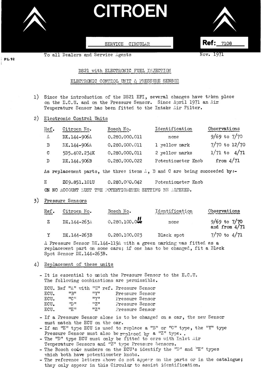
- 2 - c) Gearbox: Gearcase modified, Pressure Regulator now fitted to LH side. Gearbox cover :- Oil filler now at front.
 Gearbox: Gearcase modified, Pressure Regulator now fitted to LH side. Gearbox cover :- Oil filler now at front.") Citroën DS Electronic Injection Course 1) Introduction:- -Why Injection? To supply to the engine the exact quantity of fuel it requires in all the different conditions of use. The beet carburettors can
Citroën DS Electronic Injection Course 1) Introduction:- -Why Injection? To supply to the engine the exact quantity of fuel it requires in all the different conditions of use. The beet carburettors can
Diagnostic Trouble Code (DTC) memory, checking and erasing
 memory, checking and erasing") Page 1 of 49 01-12 Diagnostic Trouble Code (DTC) memory, checking and erasing Check DTC Memory (function 02) - Connect VAS5051 tester Page 01-7 and select vehicle system "01 - Engine electronics". Engine
Page 1 of 49 01-12 Diagnostic Trouble Code (DTC) memory, checking and erasing Check DTC Memory (function 02) - Connect VAS5051 tester Page 01-7 and select vehicle system "01 - Engine electronics". Engine
13A-1 FUEL CONTENTS MULTIPOINT FUEL INJECTION (MPI) FUEL SUPPLY... 13B
 FUEL SUPPLY... 13B") 13A-1 FUEL CONTENTS MULTIPOINT FUEL INJECTION (MPI)... 13A FUEL SUPPLY... 13B 13A-2 MULTIPOINT FUEL INJECTION (MPI) CONTENTS GENERAL INFORMATION... 3 SERVICE SPECIFICATIONS... 6 SEALANT... 6 SPECIAL TOOLS...
13A-1 FUEL CONTENTS MULTIPOINT FUEL INJECTION (MPI)... 13A FUEL SUPPLY... 13B 13A-2 MULTIPOINT FUEL INJECTION (MPI) CONTENTS GENERAL INFORMATION... 3 SERVICE SPECIFICATIONS... 6 SEALANT... 6 SPECIAL TOOLS...
Chapter 4 Part D: Fuel and exhaust systems - Magneti Marelli injection
 4D 1 Chapter 4 Part D: Fuel and exhaust systems - Magneti Marelli injection Contents Accelerator cable - removal and..................... 11 Air cleaner element - renewal..............................
TECHNICAL MANUAL L-JETRONIC FUEL INJECTION SYSTEM PORSCHE 912E
 TECHNICAL MANUAL L-JETRONIC FUEL INJECTION SYSTEM PORSCHE 912E 1 TABLE OF CONTENTS 1.0 Introduction to L-Jetronic Fuel Injection 2.0 L-Jetronic Fuel Injection Theory of Operation 3.0 L-Jetronic Component
Fuel injection system, servicing
 24-1 Fuel injection system, servicing Component locations overview 1 - Oxygen sensor 1 before Three Way Catalyst G39 2 - Oxygen sensor 2 after Three Way Catalyst G130 3 - Engine Coolant Temperature sensor
FUEL 13-1 CONTENTS MULTIPOINT INJECTION (MPI)... 2 FUEL SUPPLY ON-VEHICLE SERVICE GENERAL SERVICE SPECIFICATIONS... 4 SEALANT...
... 2 FUEL SUPPLY ON-VEHICLE SERVICE GENERAL SERVICE SPECIFICATIONS... 4 SEALANT...") 13-1 FUEL CONTENTS MULTIPOINT INJECTION (MPI)....... 2 GENERAL............................... 2 Outline of Change......................... 2 SERVICE SPECIFICATIONS.............. 4 SEALANT...............................
13-1 FUEL CONTENTS MULTIPOINT INJECTION (MPI)....... 2 GENERAL............................... 2 Outline of Change......................... 2 SERVICE SPECIFICATIONS.............. 4 SEALANT...............................
Audi A3 Current Flow Diagram No. 75 / 1 Edition Audi A3 (1,8 l litre fuel injection engine, 110 kw, Motronic, 4-cylinder) engine codes AQA
 engine codes AQA") Strona 1 z 10 Audi A3 Current Flow Diagram No. 75 / 1 Edition 09.1999 Audi A3 (1,8 l litre fuel injection engine, 110 kw, Motronic, 4-cylinder) engine codes AQA From model year 1999 Audi A3 (1,8 l litre
Strona 1 z 10 Audi A3 Current Flow Diagram No. 75 / 1 Edition 09.1999 Audi A3 (1,8 l litre fuel injection engine, 110 kw, Motronic, 4-cylinder) engine codes AQA From model year 1999 Audi A3 (1,8 l litre
TROUBLESHOOTING FOR EFI ELECTRONIC CIRCUIT WITH VOLT/OHMMETER
 FI118 TROUBLESHOOTING FOR EFI ELECTRONIC CIRCUIT WITH VOLT/OHMMETER HINT: Because the following troubleshooting procedures are designed for inspection of each separate system, the actual troubleshooting
DTC P1351 Ignition Coil Control Circuit High Voltage
 Page 1 of 5 1996 Chevrolet Chevy K Pickup - 4WD Chevy Pickup, GMC Pickup, Suburban, Tahoe, Yukon (VIN C/K) Service Manual Document ID: 34079 DTC P1351 Ignition Coil Control Circuit High Voltage Circuit
MULTIPOINT FUEL INJECTION (MPI) <4G9>
 <4G9>") MULTIPOINT FUEL INJECTION (MPI) 13C-1 MULTIPOINT FUEL INJECTION (MPI) CONTENTS GENERAL................................. 2 Outline of Changes............................ 2 GENERAL INFORMATION...................
MULTIPOINT FUEL INJECTION (MPI) 13C-1 MULTIPOINT FUEL INJECTION (MPI) CONTENTS GENERAL................................. 2 Outline of Changes............................ 2 GENERAL INFORMATION...................
3.1 LH Sequential Multiport Fuel Injection System (LH-SFI) Engines 104, 119
 Engines 104, 119") Preliminary work:................... Engine Test and Adjustment, Engines, Volume 1 On-Off Ratio Test The on-off ratio tests the operation of the O2S (Lambda) control system and additionally, recognizes
Preliminary work:................... Engine Test and Adjustment, Engines, Volume 1 On-Off Ratio Test The on-off ratio tests the operation of the O2S (Lambda) control system and additionally, recognizes
FUEL 13-1 CONTENTS MULTIPOINT INJECTION (MPI)... 2 GENERAL INFORMATION... 2 SERVICE SPECIFICATIONS... 3 SEALANT... 3 SPECIAL TOOLS...
... 2 GENERAL INFORMATION... 2 SERVICE SPECIFICATIONS... 3 SEALANT... 3 SPECIAL TOOLS...") 13-1 FUEL CONTENTS MULTIPOINT INJECTION (MPI)....... 2 GENERAL INFORMATION................ 2 SERVICE SPECIFICATIONS.............. 3 SEALANT............................... 3 SPECIAL TOOLS........................
13-1 FUEL CONTENTS MULTIPOINT INJECTION (MPI)....... 2 GENERAL INFORMATION................ 2 SERVICE SPECIFICATIONS.............. 3 SEALANT............................... 3 SPECIAL TOOLS........................
1983 BMW 320i. 1.8L 4-CYL 1983 Engines - 1.8L 4-Cylinder Engines - 1.8L 4-Cylinder
 ENGINE IDENTIFICATION 1.8L 4-CYL 1983 Engines - 1.8L 4-Cylinder For engine repair procedures not covered in this article, see ENGINE OVERHAUL PROCEDURES - GENERAL INFORMATION article in the GENERAL INFORMATION
Audi A4 Current Flow Diagram No. 4 / 1 Edition
 Стр. 1 из 11 Audi A4 Current Flow Diagram No. 4 / 1 Edition 10.2001 Audi A4 (1.8 litre fuel injection engine, 110 kw, Motronic (5-valve/turbo), 4-cylinder), engine codes APU/ANB From model year 2000 Audi
5. Engine Control Module (ECM) I/O Signal
 I/O Signal") 5. A: ELECTRICAL SPECIFICATION B134 B135 B136 B137 17 16 15 14 13 12 11 10 9 8 27 26 25 24 23 22 21 20 19 18 34 33 32 31 30 29 28 19 18 17 16 15 14 13 12 11 10 9 8 27 26 25 24 23 22 21 20 35 34 33 32 31
5. A: ELECTRICAL SPECIFICATION B134 B135 B136 B137 17 16 15 14 13 12 11 10 9 8 27 26 25 24 23 22 21 20 19 18 34 33 32 31 30 29 28 19 18 17 16 15 14 13 12 11 10 9 8 27 26 25 24 23 22 21 20 35 34 33 32 31
ENGINE AND EMISSION CONTROL
 17-1 ENGINE AND EMISSION CONTROL CONTENTS EMISSION CONTROL SYSTEM... 2 GENERAL... 2 Outline of Changes... 2 GENERAL INFORMATION... 2 SERVICE SPECIFICATION... 2 VACUUM HOSE... 3 Vacuum Hose Piping Diagram...
GENERAL <ELECTRICAL>
 00E-1 GROUP 00E GENERAL CONTENTS HARNESS CONNECTOR INSPECTION................... 00E-2............. 00E-6................. 00E-6 TROUBLESHOOTING STEPS.......... 00E-6 INFORMATION FOR DIAGNOSIS.......
Telephone: Fax: VAT Registration No.:
 Telephone: Fax: VAT Registration No.: Name: Manufacturer: Ford Address: Model: Scorpio Year: 1991 Registration: Tel - Private: Tel - Business: Mileage: Job number: Terminal side Wire side Component/circuit
Telephone: Fax: VAT Registration No.:
 Telephone: Fax: VAT Registration No.: Name: Manufacturer: Ford Address: Model: Year: 1994 Registration: Tel - Private: Tel - Business: Mileage: Job number: Terminal side Wire side Component/circuit description
Rover SD1 Efi System Fuel Supply Components - Explanation and Testing of the Fuel Pump, Filter and Fuel Pressure Regulator
 Rover SD1 Efi System Fuel Supply Components - Explanation and Testing of the Fuel Pump, Filter and Fuel Pressure Regulator Introduction Some of the notes here are repetitious in order to review the components
CONFIGURATION DIAGRAMS
 GROUP 80 CONFIGURATION DIAGRAMS CONTENTS OVERALL CONFIGURATION DIAGRAM...................... 80-2......... 80-3 .. 80-3 .. 80-5 ...... 80-7 INSTRUMENT PANEL............ 80-9 FLOOR
Audi A4 Current Flow Diagram No. 44 / 1 Edition
 Page 1 of 16 Audi A4 Current Flow Diagram No. 44 / 1 Edition 05.2003 1.8 l - Fuel injection engine (110 kw - Motronic - 4 cylinder), engine code AVJ from model year 2002 1.8 l - Fuel injection engine (120
Electronic Engine Power Control (EPC) (E-Gas), checking
 (E-Gas), checking") Page 1 of 51 24-113 Electronic Engine Power Control (EPC) (E-Gas), checking E-Gas system, function For E-Gas, the throttle valve is not operated by a cable from the accelerator pedal. There is no mechanical
Page 1 of 51 24-113 Electronic Engine Power Control (EPC) (E-Gas), checking E-Gas system, function For E-Gas, the throttle valve is not operated by a cable from the accelerator pedal. There is no mechanical
PLATINUM Sport Haltech GM LS1 / LS6 Terminated Engine Harness (HT045650) QUICK START GUIDE
 QUICK START GUIDE") PLATINUM Sport 2000 Haltech GM LS1 / LS6 Terminated Engine Harness (HT045650) QUICK START GUIDE LIMITED WARRANTY Lockin Pty Ltd trading as Haltech warrants the Haltech TM Programmable Fuel Injection System
PLATINUM Sport 2000 Haltech GM LS1 / LS6 Terminated Engine Harness (HT045650) QUICK START GUIDE LIMITED WARRANTY Lockin Pty Ltd trading as Haltech warrants the Haltech TM Programmable Fuel Injection System
FUEL SYSTEM PRECAUTION FU 1
 2GR-FE EL EL SYSTEM EL SYSTEM PRECAUTION 1 1. EXPRESSIONS OF IGNITION SWITCH (a) The type of the ignition switch used on this model differs according to the specifications of the vehicle. The expressions
ENGINE MANAGEMENT SYSTEM. System Sensors
 ENGINE MANAGEMENT SYSTEM System Sensors Throttle position sensor - Used to relay throttle position information to the ECU. Throttle opening angle is used by the ECU to determine fuelling and ignition requirements
Diagnostic Trouble Code (DTC) table
 table") Page 1 of 40 01-19 Diagnostic Trouble Code (DTC) table Note: When malfunctions occur in monitored sensors or components, Diagnostic Trouble Codes (DTCs) are stored in DTC memory with a description of the
Page 1 of 40 01-19 Diagnostic Trouble Code (DTC) table Note: When malfunctions occur in monitored sensors or components, Diagnostic Trouble Codes (DTCs) are stored in DTC memory with a description of the
PLATINUM. Sport Haltech 13B Terminated Engine Harness QUICK START GUIDE
 PLATINUM Sport 1000 Haltech 13B Terminated Engine Harness QUICK START GUIDE HALTECH HEAD OFFICE: PH: +612 9729 0999 FAX: +612 9729 0900 EMAIL: sales@haltech.com HALTECH US OFFICE: EMAIL: usa@haltech.com
ENGINE CONTROL (5VZ-FE)
") ENGINE CONTROL (VZ-FE) SYSTEM OUTLINE The engine control system utilizes a microcomputer and maintains overall control of the engine transmission etc. An outline of engine control is given here.. INPUT
ENGINE CONTROL (VZ-FE) SYSTEM OUTLINE The engine control system utilizes a microcomputer and maintains overall control of the engine transmission etc. An outline of engine control is given here.. INPUT
ENGINE ELECTRICAL Click on the applicable bookmark to selected the required model year
 ENGINE ELECTRICAL 16-1 ENGINE ELECTRICAL CONTENTS CHARGING SYSTEM................ 2 GENERAL INFORMATION................ 2 SERVICE SPECIFICATIONS.............. 3 SPECIAL TOOL......................... 3
GENERAL <ELECTRICAL>
 00E-1 GROUP 00E GENERAL CONTENTS HARNESS CONNECTOR INSPECTION................................. 00E-2............. 00E-6................. 00E-6 TROUBLESHOOTING STEPS.......... 00E-6 INFORMATION
Items Vehicles with 4G63 engine Vehicles with 4D56 engine. Type 4-speed full automatic 4-speed full automatic. 2nd rd
 23-2 AUTOMATIC TRANSMISSION General Information/ Service Specifications GENERAL INFORMATION 23100010141 Items Vehicles with 4G63 engine Vehicles with 4D56 engine Transmission model R4AW2-6 V4AW2-6 Type
FITTING INSTRUCTIONS
 FITTING INSTRUCTIONS Read carefully all sections before proceeding with any fitting OPTRONIC CLASSIC COLLECTION PMC 50 Requires FK fitting kit sold separately Thank you for purchasing this Lumenition Ignition
TUNE-UP - 4-CYL Jeep Cherokee IDENTIFICATION ENGINE IDENTIFICATION TUNE-UP NOTES TESTING ENGINE COMPRESSION SPARK PLUGS
 TUNE-UP - 4-CYL 1988 Jeep Cherokee 1988 Jeep 4 Tune-Up TUNE-UP All Models IDENTIFICATION ENGINE IDENTIFICATION Engine can be identified by the 4th character of the Vehicle Identification Number (VIN).
ELITE 1000/1500 Dodge SRT QUICK START GUIDE HT
 E N G I N E M A N A G E M E N T S Y S T E M S ELITE 1000/1500 Dodge SRT4 03-05 QUICK START GUIDE HT-140940 LIMITED WARRANTY Lockin Pty Ltd trading as Haltech warrants the HaltechTM Programmable Fuel Injection
Chapter 5 Part B: Ignition system - transistorised type
 5B 1 Chapter 5 Part B: Ignition system - transistorised type Contents Coil - testing........................................... 9 Distributor - overhaul..................................... 7 Distributor
1993 ENGINE PERFORMANCE Volkswagen Basic Diagnostic Procedures. Cabriolet, Corrado SLC, EuroVan, Fox, Golf, GTI, Jetta, Passat GL, Passat GLX
 Article Text ARTICLE BEGINNING 1993 ENGINE PERFORMANCE Volkswagen Basic Diagnostic Procedures Cabriolet, Corrado SLC, EuroVan, Fox, Golf, GTI, Jetta, Passat GL, Passat GLX INTRODUCTION The following diagnostic
G - TESTS W/CODES - 2.2L
 G - TESTS W/CODES - 2.2L 1994 Toyota Celica 1994 ENGINE PERFORMANCE Toyota 2.2L Self-Diagnostics Celica INTRODUCTION If no faults were found while performing F - BASIC TESTING, proceed with self-diagnostics.
ENGINE CONTROL (2RZ FE)
") ENGINE CONTROL (RZ FE) IF (A/T) AM IG 6 FROM POER SOURCE SYSTEM (SEE PAGE 44) AM ACC IG ST IF. A STA F FUSE O. A IGN A EFI 0A OD A STOP I4 IGNITION S (A/T) (A/T) F 0 (M/T) Y Y V (A/T) IK3 (A/T) (M/T) 3
ENGINE CONTROL (RZ FE) IF (A/T) AM IG 6 FROM POER SOURCE SYSTEM (SEE PAGE 44) AM ACC IG ST IF. A STA F FUSE O. A IGN A EFI 0A OD A STOP I4 IGNITION S (A/T) (A/T) F 0 (M/T) Y Y V (A/T) IK3 (A/T) (M/T) 3
MALLORY FIRESTORM CD MULTI COIL HARDWARE INSTALLATION - PN 69150C / 69150R
 FORM 69150C/R MALLORY FIRESTORM CD MULTI COIL HARDWARE INSTALLATION - PN 69150C / 69150R To ensure you are using the most current instruction sheet, please visit www.malloryfirestorm.com. CAUTION! The
EFI HARNESS KIT , & Kit Contents: Power Harness : All Kits
 EFI HARNESS KIT 558-500, 558-501 & 558-502 Kit Contents: Main Harness 558-102: Kits 558-500 558-103: Kits 558-501 & 502 Power Harness 558-308: All Kits Injector Harness 558-200: Kits 558-500 & 502 558-201:
TECHNICAL SERVICE PARTS
 B C1 Fuel Pump Check Valves Connector Plug Kits Connector Plugs Terminals Protective Rubber Boots Miscellaneous Service Parts General Service Tools Fuel Distributor Service Parts C2 B FUEL PUMP CHECK VALVE
Electronic Control System
 Electronic Control System PRECAUTION AT79 Do not open the cover or the case of the ECM and various computer unless absolutely necessary. (If the IC terminals are touched, the IC may be destroyed by static
Lamborghini Huracan Kit
 Lamborghini Huracan Kit Thank you for choosing the Syvecs Huracan kit The kit comes with the following: 1 x Syvecs S12 Ecu 1 x GDI12 Driver 1 x Wiring Loom Installation 1.) Remove the Negative Terminal
MALLORY FIRESTORM CD MULTI COIL HARDWARE INSTALLATION - PN 69050S / 69050R
 FORM 69050S/R MALLORY FIRESTORM CD MULTI COIL HARDWARE INSTALLATION - PN 69050S / 69050R To ensure you are using the most current instruction sheet, please visit www.malloryfirestorm.com. CAUTION! The
Fuel Metering System Component Description
 1999 Chevrolet/Geo Tahoe - 4WD Fuel Metering System Component Description Purpose The function of the fuel metering system is to deliver the correct amount of fuel to the engine under all operating conditions.
Diag. Code 14, 15 Ignition Signal Circuit
 TR26 EINE TROUBLESHOOTI Diag. Code 14, 15 Ignition Signal Circuit CIRCUIT DESCRIPTION The ECU determines the ignition timing, turns on Tr1 at a predetermined angle ( CA) before the desired ignition timing
Manual. Engine SOLO type i
 for the Engine SOLO type Serial - no.... Manufactured... Aircraft - type... Registration no.... Owner... Log of revisions no. Edition date revised page no. date of entry 1 01.09.2010 1-9 01. September
SPEED SHIFT/TWO-STEP MODULE INSTALLATION MANUAL
 SPEED SHIFT/TWO-STEP MODULE INSTALLATION MANUAL ALTHOUGH THIS PRODUCT HAS BEEN THOROUGHLY TESTED KPIERSON TECHNOLOGIES ASSUMES NO RESPONSIBILITY FOR ANY DAMAGE THAT MAY RESULT BY THE INSTALLATION OF THIS
HOWELL INSTALLATION MANUAL. Throttle Body Fuel Injection Harness
 HOWELL ENGINE DEVELOPMENTS, INC. FUEL INJECTION APPLICATIONS INSTALLATION MANUAL Throttle Body Fuel Injection Harness Howell Engine Developments, Inc. 6201 Industrial Way Marine City, MI 48039 Phone: 810-765-5100
BASIC DIAGNOSTIC PROCEDURES
 BASIC DIAGNOSTIC PROCEDURES 2001 Chevrolet Camaro 2001 ENGINE PERFORMANCE Basic Diagnostic Procedures - Cars Except Metro & Prizm MODEL IDENTIFICATION MODEL IDENTIFICATION Body Code (1) Model C... Park
G - TESTS W/CODES Volvo 960 INTRODUCTION SELF-DIAGNOSTIC SYSTEM ENGINE PERFORMANCE Volvo Self-Diagnostics
 G - TESTS W/CODES 1994 Volvo 960 1994 ENGINE PERFORMANCE Volvo Self-Diagnostics 960 INTRODUCTION If no faults were found while performing BASIC DIAGNOSTIC PROCEDURES, proceed with SELF-DIAGNOSTIC SYSTEM.
New Model Information
 Distribute to: Sales div. Service div. Parts div. Accounting div. No.06-002 New Model Information The next generation of direct fuel injection outboard motor equipped with a 32 bit ECU (Engine Control
TELORVEK TPI WIRING INSTRUCTIONS FOR TH-90 (95 CK TRUCK) 4.3,5.0,5.7,7.4 TBI Fuel Injection System W/4L60-E or 4L80-E Transmission
 4.3,5.0,5.7,7.4 TBI Fuel Injection System W/4L60-E or 4L80-E Transmission") Page #1 TELORVEK TPI WIRING INSTRUCTIONS FOR TH-90 (95 CK TRUCK) 4.3,5.0,5.7,7.4 TBI Fuel Injection System W/4L60-E or 4L80-E Transmission Thank you for purchasing the absolute finest of wiring kits for
Page #1 TELORVEK TPI WIRING INSTRUCTIONS FOR TH-90 (95 CK TRUCK) 4.3,5.0,5.7,7.4 TBI Fuel Injection System W/4L60-E or 4L80-E Transmission Thank you for purchasing the absolute finest of wiring kits for
TELORVEK EFI 5.0 Coyote Sequential Fuel Injection System Part # CY-11
 Page #1 TELORVEK EFI 5.0 Coyote Sequential Fuel Injection System Part # CY-11 WIRING INSTRUCTIONS Thank you for purchasing the absolute finest of wiring kits for the Ford Motor Co. Coyote modular engine.
H - TESTS W/O CODES Volvo 960 INTRODUCTION SYMPTOMS SYMPTOM DIAGNOSIS ENGINE PERFORMANCE Volvo Trouble Shooting - No Codes
 H - TESTS W/O CODES 1994 Volvo 960 1994 ENGINE PERFORMANCE Volvo Trouble Shooting - No Codes Volvo; 850, 940, 960 INTRODUCTION Before diagnosing symptoms or intermittent faults, perform steps in appropriate
Powertrain DTC Summaries EOBD
 Powertrain DTC Summaries Quick Reference Diagnostic Guide Jaguar X-TYPE 2.0 L 2002.25 Model Year Refer to page 2 for important information regarding the use of Powertrain DTC Summaries. Jaguar X-TYPE 2.0
Function of Preglow System
 15-0705 Function of Preglow System General On a diesel engine, combustion occurs when the fuel is injected into the highly compressed and thus greatly heated combustion air and selfignites. When the engine
Installation location The DME control unit is located in the electronics box on the bulkhead (illustration shows E65).
.") DME control unit: N62TU meeknet.co.uk/e64 Installation location The DME control unit is located in the electronics box on the bulkhead (illustration shows E65). Item Description Item Description 1 Electronics
DME control unit: N62TU meeknet.co.uk/e64 Installation location The DME control unit is located in the electronics box on the bulkhead (illustration shows E65). Item Description Item Description 1 Electronics
1994 ENGINE PERFORMANCE TOYOTA SYSTEM & COMPONENT TESTING
 1 of 65 12/5/2014 1:13 PM 1994 ENGINE PERFORMANCE TOYOTA SYSTEM & COMPONENT TESTING INTRODUCTION Before testing separate components or systems, perform procedures in articles listed below: BASIC TESTING
Motronic September 1998
 The Motronic 1.8 engine management system was introduced with the 1992 Volvo 960. The primary difference between this Motronic system and the previous generation of Volvo LH-Jetronic engine management
A: ENGINE CONTROL MODULE (ECM) I/O SIGNAL FOR MT VEHICLES. Signal (V) Ignition SW ON (Engine OFF) B B B
 I/O SIGNAL FOR MT VEHICLES. Signal (V) Ignition SW ON (Engine OFF) B B B") 5. Specified Data A: ENGINE CONTROL MODULE (ECM) I/O SIGNAL FOR MT VEHICLES B2M2267A Crankshaft Camshaft Throttle Rear oxygen Front oxygen (A/F) heater Rear oxygen heater Engine coolant temperature Signal
5. Specified Data A: ENGINE CONTROL MODULE (ECM) I/O SIGNAL FOR MT VEHICLES B2M2267A Crankshaft Camshaft Throttle Rear oxygen Front oxygen (A/F) heater Rear oxygen heater Engine coolant temperature Signal
Error Codes TOYOTA SUPRA MA70
 Code Error 11 (+B) Error Codes TOYOTA SUPRA MA70 Momentary interruption in power supply to. Ignition switch circuit Ignition switch Main relay circuit Main relay 12 RPM Signal No "NE" or "G" signal to
NEW FEATURES 3E E ENGINE. 1. Description 12 TERCEL NEW FEATURES
 12 TERCEL NEW FEATURES NEW FEATURES 3E E ENGINE 1. Description The 3E E engine is based on the 1.5 liter, 12 valve, OHC 3E engine, but with fuel injection, ignition timing and other engine functions controlled
TELORVEK III. WIRING INSTRUCTIONS FOR LT-40 LT-1 Fuel Injection System
 TELORVEK III WIRING INSTRUCTIONS FOR LT-40 LT-1 Fuel Injection System Page #1 Thank you for purchasing the absolute finest of wiring kits for the General Motors fuel injection. We have taken considerable
D - ADJUSTMENTS Nissan 240SX ENGINE COMPRESSION VALVE CLEARANCE IGNITION TIMING ENGINE PERFORMANCE On-Vehicle Adjustments
 D - ADJUSTMENTS 1990 Nissan 240SX 1990 ENGINE PERFORMANCE On-Vehicle Adjustments Nissan; Axxess, Stanza, 240SX ENGINE COMPRESSION 1) Start engine and warm to normal operating temperature. Disconnect distributor
G - TESTS W/CODES Nissan 240SX * PLEASE READ THIS FIRST * INTRODUCTION SELF-DIAGNOSTIC SYSTEM DESCRIPTION HARD FAILURES INTERMITTENT FAILURES
 G - TESTS W/CODES 1990 Nissan 240SX 1990 ENGINE PERFORMANCE Self-Diagnostics Nissan 240SX and Axxess * PLEASE READ THIS FIRST * NOTE: This article has been revised according to Technical Service Bulletin
Diagnostic Trouble Code (DTC) List - Vehicle
 List - Vehicle") Document ID# 850406 2002 Pontiac Firebird Diagnostic Trouble Code (DTC) List - Vehicle DTC DTC 021 and/or 031 DTC 022 and/or 032 DTC 023 or 033 DTC 24/34 DTC 025 and/or 035 DTC 041 DTC 042 DTC 043 DTC
Document ID# 850406 2002 Pontiac Firebird Diagnostic Trouble Code (DTC) List - Vehicle DTC DTC 021 and/or 031 DTC 022 and/or 032 DTC 023 or 033 DTC 24/34 DTC 025 and/or 035 DTC 041 DTC 042 DTC 043 DTC
The following flow charts and schematics are courtesy of General Motors Corp. Chart No. No Malfunction Indicator Lamp (MIL)
") Page 1 of 13 DIAGNOSTIC CHARTS NOTE: The following flow charts and schematics are courtesy of General Motors Corp. DIAGNOSTIC CHARTS Malfunction (1) Chart No. No Malfunction Indicator Lamp (MIL) (2) A1-1
Page 1 of 13 DIAGNOSTIC CHARTS NOTE: The following flow charts and schematics are courtesy of General Motors Corp. DIAGNOSTIC CHARTS Malfunction (1) Chart No. No Malfunction Indicator Lamp (MIL) (2) A1-1
VAGABOND S HANDBOOK TRANSMISSION
 03/24/07 TRANSMISSION Transmission won t engage into Gear This is caused usually by too low a Voltage to get into the ECM. This unit requires a minimum of 9VDC in order to operate at all. Almost all erratic
How To Wire A Rotary Engine
 Image from MotoIQ.com T - Trailing (Top) L - Leading (Lower) Rotor #1 Secondary Rotor #2 Secondary * Note: Rotor #1 is the Front Rotor Rotor #1 Primary Rotor #2 Primary 2 Rotor Installation Direct Fire
 Page 1 of 6 NO START - ENGINE CRANKS OKAY General Inspection 1. Ensure proper starting procedure is being used. 2. Visually check vacuum hoses for splits, kinks and improper connections. See underhood