GEISLINGER MONITORING
|
|
|
- Raymond Evans
- 5 years ago
- Views:
Transcription

1 GEISLINGER MONITORING


2 GEISLINGER MONITORING The Geislinger Monitoring System (GMS) is a continuous monitoring and measuring system for rotating components. It is intended for use in a wide range of applications, such as marine propulsion, power generation, wind power, compressors, and the oil and gas industry. The GMS is usually used in conjunction with Geislinger Torsional Vibration Dampers and Torsional Elastic Couplings. Its main task is to monitor the components and recognize functional deviations. When safety limits are reached or exceeded, an alarm is triggered. This allows the user to take appropriate measures to prevent component or system failures. The GMS Mark 5 provides additional features and can monitor multiple parameters simultaneously. The advanced user interface provides a fast and better insight into the condition of Geislinger products and thus helps to save costs. DESCRIPTION The GMS has a modular design and can be customized by adding additional monitoring functionalities or algorithms. It provides an easy-to-use USB interface for data acquisition. Intuitive operation by just pressing a single touch-button goes in-line with the robust design and guarantees reliable operation even under the roughest conditions. Reliable sensors in combination with sturdy measuring gears detect torsional vibrations precisely in couplings, dampers, camshafts and drive shafts. Customized algorithms filter and calculate static and dynamic twists between the elements as well as the vibratory angle. The calculated torsional vibration values are shown on the colour display as figures, bar graphs or as FFT analyzed values. If the operating limit is exceeded, an alarm is activated. The system features internal data recording from this valuable information, Geislinger specialists can evaluate if the damper or coupling is functioning correctly. The statement issued can be used as an official service document. It is recognized by classification societies and can also prevent carrying out an overhaul. TECHNICAL DATA Self-monitoring system unit with a malfunction alarm IP54 (display unit, front only) and IP67 (junction box) 6 digital inputs and 4 analogue inputs USB 2.0 for data acquisition and programming Ethernet connection(1 GB/s) for ship network integration Modbus and CAN interfaces for integration into AMS 4 potential-free relay switches for alarm output Analogue Output (4 20 ma) TFT colour display, touch-button operation ISO-fitting dimensions 192 x 147 mm 24 V DC power supply, overvoltage protection Maximum operating temperatures: Unit: 55 C, Inductive sensors: 100 C DNV type approval and tested according to IACS E-10 ADVANTAGES Additional operational safety, low running costs, increased service life due to any problems being detected early Simple monitoring of torsional vibrations Modular design, easily expandable Integration into the ship s network or existing AMS Geislinger Worldwide After Sales Service APPLICATIONS Misfiring (free-end) Monitoring: If a cylinder misfires, the alarm signal can be used as a warning to reduce the engine load or to disengage a clutch to avoid excessive vibration levels and further subsequent damage. Damper Monitoring: Ensures trouble free operation of Geislinger Dampers. Oil Pressure and Temperature Monitoring: Sensors inside the Geislinger oil supply are available as an option for 2-stroke applications. Axial Vibration Monitoring: This option, available for 2-stroke applications only, reduces the number of monitoring systems, minimizing additional costs. Coupling Monitoring: Static and dynamic twists are calculated; both the power transmitted and torque are displayed. Power Monitoring: Engine output and shaft line vibrations are displayed to optimize fuel consumption and increase the propulsion safety level. Multiple Product Monitoring: Multiple Geislinger products can be monitored on one or several engines. Double-engine Monitoring: Two engines can be monitored simultaneously with only one system unit. State of the Art Connectivity Reliable Sensors
3 Preamble This catalog replaces all old catalog versions. The content of this catalog is indicative and based on new developments Geislinger reserves the right to change the content without prior notice. All duplication, reprinting and translation rights are reserved. Should you have questions, remarks or inquiries please contact us per e mail (info@geislinger.com) or telephone ( ). The latest version of all Geislinger catalogs can be found on our website Geislinger.com. Geislinger GmbH, 5300 Hallwang, Austria
4 Index Introduction... 2 Components... 3 Functional Description... 7 Features... 9 Standard Monitoring Functions Miscellaneous Applications Technical Data Examples Geislinger GmbH, 5300 Hallwang, Austria Monitoring Catalog Version / 30
5 Introduction The Geislinger Monitoring GMS Mark5 (5 th generation) is an instrument designed to continuously monitor the torsional vibration amplitudes of a reciprocating internal combustion engine. The main advantages of the Geislinger Monitoring are: Optimum operation of the engine due to early detection of torsional vibration problems. Monitoring of a damper/coupling to determine the exact condition of the damper/coupling before an engine overhaul or dry docking. If the evaluation of the measurements shows that the damper/coupling is working properly, it can be justified in front of the classification society, that no overhaul is necessary. Should an overhaul be necessary it can be planned and the spare parts can be ordered in time. Reduction of maintenance cost and time during dry docking or engine overhaul. Increased life of the monitored installation with longer inspection intervals. Easy to use for torsional vibration measurements. Power Monitoring with high accuracy. The system gives an alarm signal when safety limits are reached or exceeded, it also indicates engine speed and operating hours. Furthermore, it can measure torsional vibration amplitudes, record the results and transmit them to a USB drive. Geislinger GmbH, 5300 Hallwang, Austria Monitoring Catalog Version / 30

6 Components The standard Geislinger Monitoring consists of three main components: System Unit Junction Box Digital Sensors System Unit Digital Sensor 2 Outer part Junction Box Digital Sensor 1 Inner part Fig.1 Standard arrangement of components Geislinger GmbH, 5300 Hallwang, Austria Monitoring Catalog Version / 30


.")

7 System Unit Fig.2 System Unit The System Unit contains a LCD display, two multicolored Alarm lights, a capacitive touch button and a printed circuit board equipped with a microprocessor which calculates primarily the phase velocity of rotating elements. By means of measurements taken on one or two of the torsional vibrating elements, for instance on a coupling or damper, the values of the static and dynamic twist between the elements and the vibratory angle of the elements are calculated. The calculated torsional vibration values and other parameters are shown on the LCD display as a graph or as fast fourier analyzed values (FFT). The power supply for the GMS and the alarm outputs (e.g. relay and analog outputs) for a Ship Control System are at the rear of the System Unit.In addition there are Ethernet and USB outputs and the inputs for up to two Junction Boxes. The System Unit also supplies the Junction Box with 24 VDC (± 15%) power. Junction Box Fig.3 Junction Box The cables from the sensors are combined to a single cable in the Junction Box which leads to the System Unit. The signals from the sensors are converted and transmitted to the System Unit. Geislinger GmbH, 5300 Hallwang, Austria Monitoring Catalog Version / 30

 Fig.")
8 Digital Sensors Fig.4 Digital hall sensor The measurement of torsional vibrations is usually done by digital hall sensors which are mounted at a fixed position and measure against the rotating wheels with grooves. If no such wheels are available, the use of angle encoders is also possible. Temperature Sensors (optional) Fig.5 Temperature sensor The temperature measurement in the oil supply is done with analog sensors, usually by a PT100 resistance sensor. Pressure Sensors (optional) Fig.6 Pressure sensor The oil pressure is measured in the oil supply. This is done by a piezoresistive pressure sensor with an analog signal output. Cabling The cable between the System Unit and the Junction Box has to be supplied by the customer. The used cables need to have a classification society approval. Geislinger GmbH, 5300 Hallwang, Austria Monitoring Catalog Version / 30
9 Standard Arrangement of the Components The sensors are equipped only with short cables to avoid distortion of the signal. Therefore the Junction Box has to be placed close to the sensors (max. distance = 1.8 m). The Junction Box can be mounted directly on to the engine or damper housing by welding the mounting plate to the engine or damper housing and screwing the Junction Box on the plate. The System Unit is usually placed in the engine control room. For dimensions of installation openings and mounting holes see chapter. ( Technical Data ) System Unit Junction Box Sensors Cabling Installed in the engine control panel in the engine control room. Close to sensors (max 1.8 m), can be mounted directly to engine or damper housing. Adjustable inductive sensors installed in fixed position with brackets inside the damper housing, bracket with inspection hole and oil tight cable gland. The cable between the System Unit and the Junction Box has to be supplied by the customer. The used cables need to have a classification society approval. Between the System Unit and the Junction Box Geislinger recommends a cable with a common copper screen, 12 conductors in twisted pairs, each conductor with a min. 0.5 mm² / max. 1.5 mm² cross section. Geislinger GmbH, 5300 Hallwang, Austria Monitoring Catalog Version / 30

10 Functional Description Display and Buttons Alarm lights Capacitive touch button USB port Display Fig.7 User interface design The design of the user interface is simple (see Fig. 7). The user has a restricted set of actions for using the system. They consist of switching or navigating between different views on the Display by using the Capacitive touch button. The user s main task is reading and controlling the measured information. The GMS supports the user by presenting the required information in different visual forms. As the GMS is a monitoring system it also displays warnings and alarms. In that case the manual confirmation of a responsible user is needed. The Geislinger Monitoring uses four types to signal abnormal conditions: Visual information on the display Alarm lights Audible signal emitted by an internal speaker Relay outputs (which can be connected to a remote ship control system) An additional possibility is to measure data recorded on a USB flash drive. Geislinger GmbH, 5300 Hallwang, Austria Monitoring Catalog Version / 30
11 Normal Operation The Geislinger Monitoring is starting up automatically after electrical power is connected. During operation the readings are taken from the sensors and processed simultaneously. The computed values of the monitoring functions are shown both as numbers and as bar graph on the display. Depending on the engine speed, the system reads the appropriate limits from the memory and compares these values with the computed values. The limits are also shown in the Limits view (Fig. 11). Geislinger GmbH, 5300 Hallwang, Austria Monitoring Catalog Version / 30
12 Features In the following section some features of the Geislinger Monitoring are described. The GMS supports different views, which display measured data and the state of the monitored component. Main, Signal and Fourier views represent the monitored data in different visual ways. Limits view contains the configured limits for the monitored components. USB view is used to record measurement data. Alarms view lists all logged alarm and warning events. The last two views, Info and Check, display system relevant information like the configuration of the monitored components and the status of the monitoring system like software version, connected modules, network status and others. All views have a consistent structure and design. At the top of each view the navigation bar is displayed. The currently selected view is highlighted. At the bottom of each view the current speed in RPM and operating hours are displayed. Additionally, if the oil temperature and oil pressure applications are installed, the current values and state of the monitored oil supply are displayed. Geislinger GmbH, 5300 Hallwang, Austria Monitoring Catalog Version / 30
13 Main view The Main view displays the current trend of the monitored component as well as the relevant actual measured values. Navigation Current value Trend bar Current state indicator Time scale Speed + Operating hours Oil supply values and status Fig.8 Main view Geislinger GmbH, 5300 Hallwang, Austria Monitoring Catalog Version / 30

14 Signal view The Signal view displays the measured value for one period in case of torsional vibrations. Those are amplitudes over the rotation angle for one cycle. Fig.9 Signal view Geislinger GmbH, 5300 Hallwang, Austria Monitoring Catalog Version / 30

15 Fourier view The Fourier view displays the fast fourier transformated signal (FFT). The values presented in this view are amplitudes of different orders of one measured period. Fig.10 Fourier view Geislinger GmbH, 5300 Hallwang, Austria Monitoring Catalog Version / 30

16 Limits view The Limits view shows the limit curves over the specified rpm range of the monitored component. Fig.11 Limits view The colors used: Orange Red = Warning limit curve = Alarm limit curve Geislinger GmbH, 5300 Hallwang, Austria Monitoring Catalog Version / 30

17 Alarms view The alarm log displays two sections: one containing active alarms and one containing already passed alarms. Fig.12 Alarm view Each alarm entry contains following fields: Source: Come: Severity: Peak: RPM: Duration: Name of the application, which signals the alarm Operating hours counter at the time of alarm occurrence Specifies the severity of the alarm event. At the moment only two classes are supported: Warning (orange) and Alarm (red). Peak value of the measurement during the alarm RPM value corresponding to the peak value Duration of the alarm event Geislinger GmbH, 5300 Hallwang, Austria Monitoring Catalog Version / 30

18 System Information view The System Information view displays the configuration of the monitored product. The configuration contains general data like configuration version and Geislinger reference number, as well as the list of monitored products and installed monitoring applications. Fig.13 System Information view Geislinger GmbH, 5300 Hallwang, Austria Monitoring Catalog Version / 30

19 System Check view The System Check view displays information about the monitoring system itself. Press and hold the capacitive touch button for at least three seconds in this view to start the Self test of the system. Fig.14 System Check view Geislinger GmbH, 5300 Hallwang, Austria Monitoring Catalog Version / 30
. The operator needs to acknowledge the event by pressing the capacitive touch button. The system logs the event and switches back to the normal view.")

20 Alarms and warnings Fig.15 Warning screen and Alarm screen The GMS detects if the monitored component exceeds alarm or warning limits. In that case the display shows a visual notification (see Fig. 15). The operator needs to acknowledge the event by pressing the capacitive touch button. The system logs the event and switches back to the normal view. All logged and active events can be reached on the Alarms page. In addition to the visual indication on the display the system sets the Alarm lights according to the actual state of the monitored component. Two LED indicators reside on the front of the System Unit: System Damper Indicates the state of the monitoring system Indicates the state of the monitored products An audible alarm and warning indicator is also integrated into the system. Alternatively external indicator modules (siren, lamps) can be connected to the relay outputs on the back of the System Unit. Recording data The Geislinger Monitoring is equipped with a USB port on the front of the System Unit. For recording measurement data just insert a USB flash drive and wait until it is recognized by the system. Geislinger GmbH, 5300 Hallwang, Austria Monitoring Catalog Version / 30
21 Standard Monitoring Functions Free End total This monitoring function shows the synthesis of the vibratory angle at the free end of the crankshaft. This indicates how balanced the engine is running. Reduced power or breakdown of a cylinder or misfiring of a cylinder increases the vibratory angle at the free end of the crankshaft. For this monitoring function the sensor signal is used which comes directly from the crankshaft resp. the damper inner part (the damper inner part is bolted to the crankshaft). Free End filtered This application calculates the vibratory angle of a single order or a range of orders at the free end of the crankshaft out of the synthesis of the vibratory angle. In many propulsion systems only a specific order or a range of orders is responsible for the critical shaft, crankshaft or intermediate shaft stress caused by torsional vibrations. Monitoring the amplitude of this order is the proper method for the detection of any dangerous operating conditions. For this monitoring function the same sensor signal as in the monitoring function Free end total is used. Damper Twist This application shows the vibratory twist angle between the damper inner part and the damper outer part. This application monitors the damper load. A broken oil supply or heavy wear of the damper springs leads to an increased vibratory twist. This will activate an alarm on the GMS. A blocked damper with no vibratory twist also causes an alarm, because other parts of the propulsion system (e.g. crankshaft, intermediate shaft) are overloaded if the damper does not work properly. Monitoring of the damper is used to determine the exact condition of the damper before an engine overhaul or dry docking. If the evaluation of the measurements shows that the damper/coupling is working properly, it can be justified against the classification society, that no overhaul is necessary. Should an overhaul be necessary, it can be planned and the spare parts can be ordered in time. Oil pressure This function measures the mean oil pressure in the oil supply and displays it at the bottom of the display.the mean value is calculated as an arithmetic mean over a working period. Oil temperature Measures the oil temperature in the oil supply and displays it at the bottom of the display. Geislinger GmbH, 5300 Hallwang, Austria Monitoring Catalog Version / 30

22 Miscellaneous What are torsional vibrations Torsional vibrations are the result of the pulsing torque of a reciprocating combustion engine and the torsional elasticity of the shaft line. All system components like crankshaft, intermediate shaft, propeller shaft and optional couplings and gears have to transmit the static torque and the additional vibratory torque. The GMS (Geislinger Monitoring System) monitors the torsional vibrations. Torsional vibration terms Order vibration frequency divided by speed Synthesis summary of single orders (order analysis) Description of signal processing The sensor which is mounted at a fixed position measures against a rotating toothed wheel, or an angle encoder mounted at the front end of a wheel or shaft supplies a digital signal. This signal switches from low output to high output when a tooth passes the sensor head. The measured signal is the elapsed time (pulse duration) between a tooth and the next tooth (see Fig. 16). The measured pulse duration is proportional to the angular velocity. A microprocessor records the signal for further signal processing. Fig.16 Signal processing Geislinger GmbH, 5300 Hallwang, Austria Monitoring Catalog Version / 30
23 A plot of the time over the angle gives a graph as shown in Fig. 17. The mean time between two teeth (constant angular velocity or rpm) can be subtracted. In the next step the time differences are transformed into angular differences based on actual engine speed (rpm). Fig.17 Plot of sensor signal After the initial transformation from time domain to angle domain the signal is split into its discrete order components. The frequencies below the first order (in case of a 2 stroke engine) or 0.5 th order (in case of a 4 stroke engine) are filtered out to remove accelerations caused by the engine speed control system. The orders above configured limits are also filtered out. The standard values are: up to a 16 th order for a 2 stroke engine and up to 12 th order for a 4 stroke engine. Those limits can be adjusted to specific requirements by reconfiguring the system. Geislinger GmbH, 5300 Hallwang, Austria Monitoring Catalog Version / 30
. The minimal order range is one order for 2 stroke engines and half for 4 stroke engines.")
24 Fig.18 Results of signal filtering The filtered orders are used to calculate the synthesis of the filtered signal. The result is the vibratory angle of the synthesis of a specified range of orders (Fig 18). The minimal order range is one order for 2 stroke engines and half for 4 stroke engines. In the last step the maximal amplitude of the vibratory (twist) angle is checked against the safety limits. These limits are depending on the engine speed (rpm). Geislinger GmbH, 5300 Hallwang, Austria Monitoring Catalog Version / 30
 is used.")
25 Applications Monitoring at free end Fig.19 Free end monitoring This function calculates the absolute torsional vibratory angle of a rotating part. In addition a range of orders or a single order can be monitored or filtered out. For this monitoring function only one sensor (inductive sensor or angle encoder) is used. Applications: Misfiring detector: The synthesis of the vibratory angle at the free end of the crankshaft indicates how balanced the engine is running. Misfiring of one or more cylinders of a combustion engine will cause an increase in loads due to torsional vibrations and may result in a damage of the propulsion system or its components. Shaft, crankshaft stress or intermediate shaft stress monitoring: In many propulsion systems only a specific order is responsible for the critical shaft, crankshaft or intermediate shaft stress caused by the torsional vibrations. Monitoring of the amplitude of this order is a proper method for detection of dangerous operating conditions. Geislinger GmbH, 5300 Hallwang, Austria Monitoring Catalog Version / 30

26 Damper monitoring Fig.20 Damper monitoring Damper Monitoring stands for monitoring the synthesis of the vibratory twist angle between two rotating parts. The two rotating parts are combined elastically. For this monitoring function two sensors are necessary. From the signal of each sensor the synthesis of all orders of the absolute vibratory angle is calculated. The synthesis of the amplitude of the difference between these values is monitored. Applications: GEISLINGER damper monitoring of the vibratory twist angle between the damper inner part and the damper outer part is necessary to control the damper load. A broken oil supply or heavy wear of the damper springs leads to an increased vibratory twist. This will activate an alarm on the GMS. A blocked damper with no vibratory twist also causes an alarm, because other parts of the propulsion system (e.g. crankshaft, intermediate shaft) are overloaded. Monitoring of the damper can be used to determine the exact condition of the damper before an engine overhaul or dry docking. If the measurements show that the damper is working properly, it can be justified with the classification society, that no damper overhaul is necessary. In the rare case that spare parts are needed, they can be ordered in time. Geislinger GmbH, 5300 Hallwang, Austria Monitoring Catalog Version / 30
 in relation to")
27 Coupling monitoring Fig.21 Coupling monitoring Coupling Monitoring stands for monitoring the synthesis of the vibratory twist angle between two rotating parts with a static offset (caused by a mean torque) in relation to the static twist angle. Based on the measured static twist, computing of the transmitted torque and power is possible. The two rotating parts are combined elastically. For this monitoring function two sensors are necessary. Both rotating parts must have a reference mark (a longer gap or tooth), which is used to recognize the static offset. The torsional stiffness of the monitored part can be entered as a cubic polynom and is used to calculate torque and transmitted power. Applications: GEISLINGER coupling monitoring: One sensor is mounted on the power input side, the other on the power output side of the coupling. The GEISLINGER coupling is equipped with elastically steel spring blades. Monitoring of the vibratory twist angle between the coupling inner part and the coupling outer part is necessary to control the coupling load. A broken oil supply or heavy wear of the coupling springs due to overload leads to an increased vibratory twist. This will activate an alarm on the GMS. A blocked coupling with no vibratory twist causes also an alarm, because other parts of the propulsion system are overloaded. Monitoring the coupling is also very useful to determine the exact condition of the coupling before an engine overhaul or dry docking. If the measurements show that the coupling is working properly, it can be justified with the classification society, that no coupling overhaul is necessary. In the rare case that spare parts are needed, they can be ordered in time. Geislinger GmbH, 5300 Hallwang, Austria Monitoring Catalog Version / 30
.")
28 Shaft monitoring: Shaft monitoring is similar to coupling monitoring. The only difference is that the stiffness of the springs is substituted by the stiffness of the shaft. The accuracy of the measured torque increases with the distance between the sensors (=length of shaft). Alarm indication When the engine is running, the readings are taken from the sensors and processed simultaneously. After the CPU has calculated the vibratory angle or vibratory twist, the results are evaluated against limit curves. Limit curves are defined as continuous lines with a maximum of 20 supporting points. Each point is defined by its coordinates. The unit of the x coordinate is rpm (or the static twist in case of coupling monitoring), the unit of the y coordinate unit is milliradian. Depending on the engine speed the system reads the appropriate limits from the memory and compares these values with the computed values for exceeding the limits. To avoid short term alarms the required number of successive alarms can be defined before an alarm is actually activated. Fig.22 Alarm indication Geislinger GmbH, 5300 Hallwang, Austria Monitoring Catalog Version / 30
29 Technical Data General technical data System Unit Permissible ambient temperature: 55 Celsius Power supply Voltage: 24 VDC ± 10% Maximum current consumption: 1 Ampere Fuse: Outputs: Inputs: Junction Box Mark4 Permissible ambient temperature: 70 Celsius Power supply Voltage: 24 VDC ± 15% Maximum current consumption: 100 ma Inputs 2 x Digital Input 4 Ampere, fast blow 4 x Relay (max. 24 VDC, 1 Ampere) 1 x Ethernet 1 GBit/s 3 x USB version x Analog output ( mamp.) 1 x RS 485 Modbus slave 2 x CAN, CAN 2.0A and 2.0B 6 x RS 485 to capture the switching times of digital signals 2 x RS 485 for the recording of analog values (max. 100 khz sampling rate) Junction Box Mark5 Permissible ambient temperature: 70 Celsius Power supply Voltage: 24 VDC ± 15% Maximum current consumption: 300 ma Inputs: 3 x Digital Input 2 x Analog Input (Sampling rate: 100Hz, Resolution: 16bit) Technical standards: Electrical and environmental testing according to IACS E 10 rules and type approval from DNV Geislinger GmbH, 5300 Hallwang, Austria Monitoring Catalog Version / 30
30 Dimensions and weights System Unit: 192 x 147 mm, Depth: 135mm (including space for cables at rear) Weight: 1.5 kg Junction Box Mark4: 130 x 130 mm (including space for cable glands) Depth: 60mm Weight: 0.6 kg Junction Box Mark5: 200x190 mm (including space for cable glands) Depth: 51 mm Weight: 1.25 kg Assembly opening for the System Unit Installation depth: 100 mm Dimension of System Unit frame: 192 x 147 mm M 4 Fig.23 Dimensions for assembly opening Geislinger GmbH, 5300 Hallwang, Austria Monitoring Catalog Version / 30

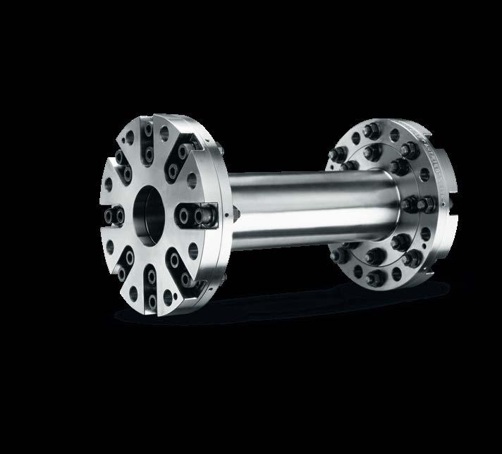
31 Examples Geislinger Monitoring used for Damper Monitoring Damper type: Damper outer diameter: Nominal damper twist: D 260/17 + Geislinger Monitoring 2600 mm 3.5 mrad This damper is designed to protect the crankshaft and therefore an important part of the main engine. Sensor 2 Junction Box Sensor 1 Fig.24 Example for Damper Monitoring Sensor 1 is mounted near the damper inner part, sensor 2 is mounted near the damper outer part. This installation is an example for the high accuracy of the Geislinger Monitoring System, because the vibratory angles are very low. In case of damper twist: 3.5 mrad; in case of free end filtered (9th order): 1.75 mrad. Geislinger GmbH, 5300 Hallwang, Austria Monitoring Catalog Version / 30

32 Geislinger Monitoring used for Coupling Monitoring Coupling type: Coupling outer diameter: Performance data: BE 180/22.5/126U + GFL S112 F8 + Geislinger Monitoring 1800 mm kw, 308 rpm, torque: 403 knm The combination of Geislinger Flexlink and Geislinger Coupling is mounted between an electric motor and a pod propeller unit. The system is designed to protect the pod propeller and to compensate for misalignments. Sensor 2 Sensor 1 Fig.25 Example for Coupling Monitoring Sensor 2 is mounted near the outer part of the Geislinger coupling (input of torque), sensor 1 is mounted near the outer part of the Geislinger Flexlink coupling (output of torque). Through this arrangement both couplings are monitored. Geislinger GmbH, 5300 Hallwang, Austria Monitoring Catalog Version / 30

,")

33 Geislinger Monitoring used for Power Monitoring The Power Monitoring is installed on ships' propeller shafts allowing the output propeller power to be monitored as part of the overall ship's fuel usage optimisation control system. Sensor 2 (turn wheel gear) Shaftline Sensor 1 (measuring gear at aft flange) Fig.26 Example for Power Monitoring Monitoring System Unit Sensor 2 is mounted at the flywheel position of the engine (input of torque), sensor 1 is mounted at the measurement ring position of the propeller side (output of torque). In common the system unit is located in the engine control room. To show the monitored power also on the bridge of the vessel it is also possible to install an optional second display. Geislinger GmbH, 5300 Hallwang, Austria Monitoring Catalog Version / 30


34 Geislinger Coupling Geislinger Silenco Geislinger Carbotorq Geislinger Damper Geislinger Monitoring Geislinger Flexlink Geislinger Vdamp Geislinger Gesilco Geislinger Gesilco Shaft Geislinger GmbH, Hallwanger Landesstrasse 3, 5300 Hallwang/Salzburg, Austria, Tel , Fax , geislinger.com
Introduction Components...3. Functional Description Features Standard Monitoring Functions Alarm Definition...
 Monitoring Index Introduction... 2 Components...3 Functional Description... 6 Features... 8 Standard Monitoring Functions... 9 Alarm Definition... 9 Technical Data...11 Miscellaneous...13 Applications...16
LIGHTWEIGHT GEISLINGER GESILCO SHAFT
 LIGHTWEIGHT GEISLINGER GESILCO SHAFT GEISLINGER GESILCO SHAFT The Geislinger Gesilco shaft product range is based on more than 20 years experience in developing fibre composite couplings and shafts. The
Geislinger Damper. The smallest possible damper for each engine
 The Geislinger damper is capable of adjusting the natural frequency of a system and of reducing torsional vibration. Thus it reliably protects the crankshafts, camshafts, intermediate and propeller shafts
Lightweight. Geislinger Gesilco
 Lightweight Geislinger Gesilco The Geislinger Gesilco product range is based on more than 20 years of experience in developing fibre composite couplings and shafts. The maintenance-free composite membranes
MARINE RAIL MINING OIL & GAS POWER GENERATION
 MARINE RAIL MINING OIL & GAS POWER GENERATION . LEADERS IN ENGINEERING. RAIL OIL & GAS Geislinger develops and produces torsion- outstanding service life and a very high times, Geislinger locations and
THE FIBRE COMPOSITE PRODUCT LINE BY GEISLINGER
 THE FIBRE COMPOSITE BUILT TO LAST. THE COMPACT AND LIGHTWEIGHT GESILCO DESIGN PAVES THE WAY FOR GREAT OPPORTUNITIES. For 60 years Geislinger has been driven by its inventive spirit to develop innovative
FATIGUE RESISTANT & MAINTENANCE- FREE GEISLINGER COMPOWIND
 FATIGUE RESISTANT & MAINTENANCE- FREE GEISLINGER COMPOWIND Courtesy of Vestas Wind Systems A/S GEISLINGER. LEADERS IN ENGINEERING. Geislinger develops and produces torsional vibration dampers, torsional
CPU-95EVS Enhanced VariSpark Digital Ignition System for Industrial Engines
 CPU-95EVS Enhanced VariSpark Digital Ignition System for Industrial Engines Features VariSpark Spark Profile Control Users can select from one of six VariSpark spark energy profiles embedded within the
MAGTROL. TF Series Torque Flange Sensor. TF data sheet FEATURES. DESCRIpTION. AppLICATIONS
 data sheet Series Torque Flange Sensor FETURES Complete torque measuring system consisting of: Measuring flange with signal amplifier HF transmitter Conditioner 4 m coaxial cable Contactless signal transmission:
CPU-95 ADVANCED DIGITAL IGNITION SYSTEM FOR INDUSTRIAL ENGINES
 New Backward-Compatible Enhanced CPU-95 Display Now Available CPU-95 ADVANCED DIGITAL IGNITION SYSTEM FOR INDUSTRIAL ENGINES Microprocessor-based, crankshaft referenced digital ignition system for medium-sized
Fuel Consumption Measurement
 Fuel Consumption Measurement 135 Introduction The Due use to the of a increasing T-Sense awareness torque measuring of the impact system of means exhaust efficiency emissions improvement, overload on the
CPU-XL VariSpark ADVANCED DIGITAL IGNITION SYSTEM FOR LARGE GAS ENGINES
 CPU-XL VariSpark ADVANCED DIGITAL IGNITION SYSTEM FOR LARGE GAS ENGINES n State-of-the-art, crankshaft-referenced digital ignition system for natural-gas fueled integral compressor engines n Innovative
MIC4 IGNITION CONTROLLER
 MIC4 IGNITION CONTROLLER MIC4 MOTORTECH IGNITION CONTROLLER Try the alternative. Call the nearest MOTORTECH sales partner for more information. REV.02/2015 MIC4 IGNITION CONTROLLER The economically attractive
Based on the findings, a preventive maintenance strategy can be prepared for the equipment in order to increase reliability and reduce costs.
 What is ABB MACHsense-R? ABB MACHsense-R is a service for monitoring the condition of motors and generators which is provided by ABB Local Service Centers. It is a remote monitoring service using sensors
T-Sense _ 660. Optical Torque Measuring Systems. Product Bulletin
 T-Sense Optical Torque Measuring Systems _ 660 Product Bulletin WWW.VAF.NL 1 Introduction The use of a T-Sense torque measuring system means efficiency improvement, overload protection and prevention of
Operating Instructions. Angle Seat Control Valve. Type 7020
 Operating Instructions Angle Seat Control Valve Type 7020 With: Digital Positioner Type 8048 Electro-pneumatic Positioner Type 8047 Pneumatic Positioner Type 8047 Version: 02/2006 Manual-7020e.doc Art.-No:
Electronic Ballast EVG 2000-T
 Electronic Ballast EVG 2000-T Operating Manual Table of contents 1 Description 1.1 Advantages of this ballast... 3 1.2 Functional principle... 3 1.3 Energization... 4 1.4 Visualization... 5 1.5 Indications
Continuous Duty Torque Measurement. Directly and accurately measures the power of turbomachinery in the Oil, Gas and Petrochemical industries.
 Continuous Duty Torquetronic TM Continuous Duty Torque Measurement. Directly and accurately measures the power of turbomachinery in the Oil, Gas and Petrochemical industries. Measuring steady state torque
CCM Marine. Optimise your engine performance
 CCM Marine Optimise your engine performance CCM Marine - Combustion Monitoring Systems CCM is an easy to use plug and play system, which enables in real time data acquisition of cylinder pressure on engines.
Marine Shaft Power Meter Product Overview
 Marine Shaft Power Meter Product Overview Introduction Datum Electronics Limited ESTABLISHED IN 1989, Datum Electronics Limited is a leading UK manufacturer and supplier of torque, load & shaft power measurement
Installation and Operational Instructions for EAS - HTL housed overload clutch Sizes 01 3 Type 490._24.0
 Please read these Operational Instructions carefully and follow them accordingly! Ignoring these Instructions may lead to malfunctions or to clutch failure, resulting in damage to other parts. Contents:
INTRODUCTION SBPT DIAPHRAGM COUPLING: FEATURES APPLICATION
 INTRODUCTION SBPT is an ISO 9001: 2000 certified company, specializing in Design and Manufactures of highly flexible Diaphragm Coupling since 1994. Advance analysis and manufacturing process have produced
W SERIES IMPULSE VOLTAGE TEST SYSTEM APPLICATION FEATURES
 W SERIES IMPULSE VOLTAGE TEST SYSTEM Impulse Voltage Test System is used to generate impulse voltages from 100 KV to 2400 KV simulating lightning strokes and switching surges with energies up to 240 KJ.
SP5 INSTALLATION AND SETUP MANUAL
 SP5 INSTALLATION AND SETUP MANUAL 1 Installation 1.1 Introduction The SP5 System consists of a Data Acquisition unit (DAQ) with two complete Roller control channels, each Roller Control Channel consists
Delomatic 400 (DM 400) based Gas Engine and Combined Heat and Power (CHP) Control and Management System
 based Gas Engine and Combined Heat and Power (CHP) Control and Management System") Table of contents 1. WARNINGS AND LEGAL INFORMATION... 3 3.5 LEGAL INFORMATION AND RESPONSIBILITY... 3 3.6 ELECTROSTATIC DISCHARGE AWARENESS... 3 3.7 SAFETY ISSUES... DELOMATIC 400 GAS 3 3.8 DISCLAIMER...
Table of contents 1. WARNINGS AND LEGAL INFORMATION... 3 3.5 LEGAL INFORMATION AND RESPONSIBILITY... 3 3.6 ELECTROSTATIC DISCHARGE AWARENESS... 3 3.7 SAFETY ISSUES... DELOMATIC 400 GAS 3 3.8 DISCLAIMER...
Sensor-Bearing Units Steer-By-Wire Modules Mast Height Control units Other sensorized units
 Mechatronics Sensor-Bearing Units... 957 Steer-By-Wire Modules... 967 Mast Height Control units... 969 Other sensorized units... 971 955 Sensor-Bearing Units SKF Sensor-Bearing Units... 958 SKF Explorer
Superstatic 440. Static Heat- and Cooling Meter. Application
 Superstatic 440 Static Heat- and Cooling Meter Application Design The Superstatic 440 is a static heat- and cooling meter according to standard EN1434 class 2 based on the fluid oscillation principle,
CENTA POWER TRANSMISSION CENTAMAX ENGLISH. Is this PDF up to date? click here for an update check!
 CENTA POWER TRANSMISSION CENTAMAX ENGLISH Is this PDF up to date? click here for an update check! CENTAMAX ROBUST. FOR TORSIONALLY ACTIVE DRIVES. SYSTEM COUPLING COMPONENTS TYPES APPLICATIONS TECHNICAL
VALVE CONTROLLERS Controllers for Dust Extr 2010 / 2011 action Technology
 VALVE CONTROLLERS Controllers for Dust Extraction 2010 Technology / 2011 Valve controllers for all cases HESCH has the skills and technology to tackle any control task for dedusting of filter and dust
Servo-pneumatic drive solution for welding guns. Top quality welding!
 Servo-pneumatic drive solution for welding guns Sturdy and precise! Top quality welding! Highlights Extremely short cycle times High quality and outstanding reproducibility of the spot welds Excellent
Copyright AREVA Wind/Jan Oelker. in wind turbines
 Copyright AREVA Wind/Jan Oelker Sensors and control systems in wind turbines 3 1 7 6 8 4 2 5 9 Sensors and control systems 15 years of experience and more than 30,000 installations worldwide Modern wind
INSTALLATION INSTRUCTIONS
 INSTALLATION INSTRUCTIONS WARNING: WARNING: www.altronicinc.com DEVIATION DEVIATION FROM THESE FROM INSTRUCTIONS THESE INSTRUCTIONS MAY LEAD MAY TO LEAD IMPROPER TO IMPROPER OP- ERATION OF ENGINE THE MACHINE
Measuring equipment for the development of efficient drive trains using sensor telemetry in the 200 C range
 News Measuring equipment for the development of efficient drive trains using sensor telemetry in the 200 C range Whether on the test stand or on the road MANNER Sensortelemetrie, the expert for contactless
T-Sense. Optical Torque Measuring systems. Product Bulletin TO BE REALLY SURE
 TSense Optical Torque Measuring systems 660 Product Bulletin WWW.VAF.NL TO BE REALLY SURE 1 Introduction Principle of operation The use of a TSense torque measuring system means efficiency improvement,
ANKERSMID Temperature controller ATC 510/520/525 for wall-mounting. Application
 2-3.1 ATC 510/520/525 for wall-mounting Application The ATC 510/5205/525 is a modern microprocessor-based (PID) control device featuring easy handling and a digital display. The clear design of the operator
PROPULSION EQUIPMENT DOCUMENTATION SHEET. Propulsion Equipment
 PROPULSION EQUIPMENT General Vessels like rescue boats, patrol boats and anchor handling boats have to show 100 percent performance, even in the most extreme conditions. These so called s pecial seagoing
Installation and Operational Instructions for ROBA -D Couplings Type 91_. _
 Please read the Installation and Operational Instructions carefully and follow them accordingly! Ignoring these Instructions may lead to malfunctions or to coupling failure, resulting in damage to other
Early failure detection on engines with multi-point vibration analysis
 Whitepaper Early failure detection on engines with multi-point vibration analysis Use cases and advantages of a novel multi-point vibration analysis for early failure detection on combustion engines Authors:
For reliable control of small, large or multi-system-type lubrication systems
 LMC 301 controller For reliable control of small, large or multi-system-type lubrication systems Models 86500, 86501 Models 86502, 86503 Designed for use with pumps that have no internal controller, the
Stepper Motors ver ver.5
 A Stepper s Stepper s A-1 Overview... A-2 Overview and... A-15 & Stepper and RK Series A-16 RK... A-47... A-51 Stepper Series A-52 Stepper Series A-8 See Full Product Details Online www.orientalmotor.com
Lexium integrated drives
 Description ILp for DeviceNet, EtherCAT, Modbus TCP, ILE with brushless DC motor Description ILE comprise control electronics with a fieldbus interface for DeviceNet, EtherCAT, Modbus TCP or and a brushless
Installation and Operational Instructions for EAS -Compact overload clutch, Type 49_. 4._ Sizes 4 and 5
 Please read these Operational Instructions carefully and follow them accordingly! Ignoring these Instructions may lead to malfunctions or to clutch failure, resulting in damage to other parts. Contents:
INTECH Micro 2300-RTD6
 INTECH Micro 2300-RTD6 6 Channel RTD Input Station Overview. The Intech Micro 2300 Series is a system of modular I/O Remote Stations, that add an even lower cost option to Intech s already extensive intelligent
ROTARY MODULES. Rotary modules
 Rotary modules Rotary modules ROTARY MODULES Series Size Page Rotary modules RM swivel unit 156 RM 08 160 RM 10 162 RM 12 164 RM 15 168 RM 21 172 RM rotor 176 RM 50 180 RM 110 182 RM 200 184 RM 310 186
Series 7000 Torque Sensor for PTO-shafts
 Properties PTO (Power Take-Off) shaft with integrated torque and angle measurement Non-contact measurement system, high robustness Special for PTO shafts 1 ¾ und 1 3/8 Plug & Play solution, no additional
M-18 Controllable-Pitch Propeller
 Guideline No.M-18(201510) M-18 Controllable-Pitch Propeller Issued date: 20 th October, 2015 China Classification Society Foreword This Guideline is a part of CCS Rules, which contains technical requirements,
Differential pressure gauge with output signal With integrated working pressure indication (DELTA-trans) Model DPGT40
 Model DPGT40") Mechatronic pressure measurement Differential pressure gauge with output signal With integrated working pressure indication (DELTA-trans) Model DPGT40 WIKA data sheet PV 17.19 Applications weitere Zulassungen
Mechatronic pressure measurement Differential pressure gauge with output signal With integrated working pressure indication (DELTA-trans) Model DPGT40 WIKA data sheet PV 17.19 Applications weitere Zulassungen
Application of Steering Robot in the Test of Vehicle Dynamic Characteristics
 3rd International Conference on Mechatronics, Robotics and Automation (ICMRA 2) Application of Steering Robot in the Test of Vehicle Dynamic Characteristics Runqing Guo,a *, Zhaojuan Jiang 2,b and Lin
Series 7000 Torque Sensor for PTO-shafts
 Properties PTO (Power Take-Off) shaft with integrated torque and angle measurement Non-contact measurement system, high robustness Special for PTO shafts 1 ¾ und 1 3/8 Plug & Play solution, no additional
ILE2K661PC1A1 brushless dc motor V- EtherNet/IP interface - L = 174 mm- 18:1
 Characteristics brushless dc motor 24..48V- EtherNet/IP interface - L = 174 mm- 18:1 Main Range of product Product or component type Device short name Motor type Number of motor poles 6 Network number
ST48-WHUV.102. Wiring diagram. Product description. PID controller. Order number
 ST48-WHUV.12 PID controller Order number 935.15 Wiring diagram Product description This micro-processed controller serves for temperature control at high measuring accuracy. Beside resistance sensors and
CHAIN WEAR ANALYSIS WITH LUBECON
 CHAIN WEAR ANALYSIS WITH LUBECON LUBECON THE EXPERT IN CHAIN WEAR ANALYSIS CASTROL S LUBECON BRAND OFFERS YOU A COMPLETE RANGE OF WORLD-CLASS CHAIN LUBRICANTS, LUBRICATING EQUIPMENT AND PRODUCT SUPPORT
SIMOTICS S-1FT7 Servomotors. The Compact Servomotors for High-Performance Motion Control Applications. Motors. Edition April 2017.
 Motors SIMOTICS S-1FT7 Servomotors The Compact Servomotors for High-Performance Motion Control Applications Brochure Edition April 2017 siemens.com/servomotors The Servomotors for High-Performance Applications
RoaDyn S: Multi-Component Test Stand Hubs
 RoaDyn S: Multi-Component Test Stand Hubs For Durability Testing RoaDyn S625 nsp: 6-Component Measuring Hub for Cars Type 92662 Measuring range F x kn 20... 20 F y kn 15... 15 F z kn 20... 20 M x kn m
Shaft Couplings Flange-Couplings Rigid Shaft Couplings Flexible Couplings
 Shaft Couplings Flange-Couplings Rigid Shaft Couplings Flexible Couplings 44 Edition 2013/2014 RINGSPANN Registered Trademark of RINGSPANN GmbH, Bad Homburg 2 Table of Contents Flange-Couplings Page Flange-Couplings
DATUM ELECTRONICS RS425 NON-CONTACT TORQUE TRANSDUCER PRODUCT OVERVIEW
 DATUM ELECTRONICS LIMITED TELEPHONE: +44 (0) 1983 28 28 34 FAX: +44 (0) 1983 28 28 35 EMAIL: support@datum-electronics.co.uk WEB: www.datum-electronics.co.uk DATUM ELECTRONICS RS425 NON-CONTACT TORQUE
Lexium integrated drives
 Description ILp for CANopen, PROFIBUS DP, RS ILE with brushless DC motor Description ILE comprise control electronics with a fieldbus interface for CANopen DS, PROFIBUS DP or RS and a brushless DC motor.
Accessories smart additions for efficiency and intelligent performance
 smart additions for efficiency and intelligent performance Metal bellows couplings Perfectionists you can count on Metal bellows couplings are designed for the highest requirements in servo drive technology.
IRT 4000 AT-S/M/L. Technical Manual. quality IN MOTION. quality IN MOTION
 IRT quality IN MOTION www.irtsa.com 4000 AT-S/M/L Technical Manual IRT quality IN MOTION E2 0 8 4 1 5 September 2013-Rev. 5 UL Requirements Drives Series 2000 / 4000 AT 1. Field wiring terminal to use
Superstatic 440. Static Heat Meter, Static Cooling Meter. Application
 Superstatic 440 Static Heat Meter, Static Cooling Meter Application Design The Superstatic 440 is a static heat or cooling meter according to standard EN1434 class 2 based on the fluid oscillation principle,
SINAMICS GM150 IGCT version
 /2 Overview /2 Benefits /2 Design /6 Function /8 Selection and ordering data /8 Options Technical data /14 General technical data /15 Control properties /15 Ambient conditions /16 Installation conditions
Reciprocating compressor diagnostics
 makes it possibile to monitor the condition of the machine and to detect any malfunctions or changes in behaviour. Diagnostics can be carried out with both a preventive and an analytical function helping
INSTALLATION USER MANUAL
 INSTALLATION & USER MANUAL DYNAMIC LOAD MANAGEMENT -PREMIUM- This document is copyrighted, 2016 by Circontrol, S.A. All rights are reserved. Circontrol, S.A. reserves the right to make improvements to
TURBOGENERATOR DYNAMIC ANALYSIS TO IDENTIFY CRITICAL SPEED AND VIBRATION SEVERITY
 U.P.B. Sci. Bull., Series D, Vol. 77, Iss. 3, 2015 ISSN 1454-2358 TURBOGENERATOR DYNAMIC ANALYSIS TO IDENTIFY CRITICAL SPEED AND VIBRATION SEVERITY Claudiu BISU 1, Florian ISTRATE 2, Marin ANICA 3 Vibration
2.1 Warnings & Agency Approvals Electrical Connections - Specifications Standard Wiring Configurations...2 4
 CHAPTER ELECTRICAL 2 INSTALLATION Contents of this Chapter... 2.1 Warnings & Agency Approvals..................2 2 2.1.1 Isolation..............................................2 2 2.1.2 Electrical Power
Differential Pressure Gauges Cryo Gauge Model , Cu-alloy Model , Stainless Steel Series
 Differential Pressure Gauges Cryo Gauge Model 712.15.160, Cu-alloy Model 732.15.160, Stainless Steel Series Mechanical Pressure Measurement WIKA Data Sheet PM 07.30 Applications Level measurement in closed
M-24 OUTBORD ENGINES
 Guideline No.: M-24(201510) M-24 OUTBORD ENGINES Issued date: October 20,2015 China Classification Society Foreword: This Guide is a part of CCS Rules, which contains technical requirements, inspection
ACTUATORS POSITION SENSOR
 POSITION SENSOR 1 2 SUMMARY P INTRODUCTION PAGE 4 P LTS POSITION SENSOR PAGE 5 P LTL POSITION SENSOR PAGE 9 SUMMARY P LTE POSITION SENSOR PAGE 12 3 INTRODUCTION INTRODUCTION Magnetic position sensors are
Motronic MS Electronic design. Functionality. Mechanical data. Conditions for use
 Motronic MS 1.10 The MS 1.10 is a highly sophisticated engine management system for high performance engines. The system contains 12 ignition power stages and 24 independent injection power stages. All
HEIDENHAIN Measuring Technology for the Elevators of the Future TECHNOLOGY REPORT. Traveling Vertically and Horizontally Without a Cable
 HEIDENHAIN Measuring Technology for the Elevators of the Future Traveling Vertically and Horizontally Without a Cable HEIDENHAIN Measuring Technology for the Elevators of the Future Traveling Vertically
General Purpose Ignition System GS6. User Manual. Document No PS-0009
 General Purpose Ignition System GS6 User Manual Document No. 1521-PS-0009 Gill Instruments Ltd Saltmarsh Park, 67 Gosport Street, Lymington, Hampshire, SO41 9EG, UK Tel: +44 1590 613500 Fax: +44 1590 613555
Saving energy while increasing productivity Servo-hydraulic drive CSH. voith.com
 voith.com Saving energy while increasing productivity Servo-hydraulic drive CSH In deep drawing presses, two subsystems play the decisive role for productivity and workpiece quality: the press drive and
WINDROCK 6400 PORTABLE ANALYZER Premium Portable Monitoring for Reciprocating Machinery
 WINDROCK 6400 PORTABLE ANALYZER Premium Portable Monitoring for Reciprocating Machinery Machine Protection Condition Monitoring Performance Analysis Economic Evaluation WINDROCK 6400: BENEFITS OF MACHINERY
Operating Instructions. Pneumatic Control Valve Low Temperature. Type Series GS3
 Operating Instructions Pneumatic Control Valve Low Temperature Type 8026 Series GS3 With: Digital Positioner Type 8048 Electro-pneumatic Positioner Type 8047 Pneumatic Positioner Type 8047 Version: 03/2006
Hybrid Control System, Alpha Step
 B Hybrid Control System, Alpha Step Hybrid Control System B-1 Overview... B-2 Overview Hybrid Control System Battery-Free, Absolute Sensor Equipped AZ Series... B-16 Electric Linear Slides EZS Series AZ
Model ED 400 Drying and heating chambers Classic.Line with natural convection
 Model ED 400 Drying and heating chambers Classic.Line with natural convection The strengths of a BINDER ED series drying chamber include routine drying and sterilization tasks up to 300 C. Thanks to the
Alpha EM DC Multi-Function DC Energy Meter. Technical Datasheet. Compact DC Energy Meter
 Alpha EM DC Technical Datasheet Compact DC Energy Meter ALPHA EM DC series is specially designed to measure, display and communicate DC Voltage, Current, Power and Energy to monitor and control the target
The Traveler Series: Adventurer
 The Traveler Series: Adventurer RENOGY 30A Flush Mount Charge Controller Manual 2775 E. Philadelphia St., Ontario, CA 91761 1-800-330-8678 Version: 2.2 Important Safety Instructions Please save these instructions.
Cobra 3 Stand-By Emergency Central Lighting Inverter (CLI) Technical Specifications
 Technical Specifications") Cobra 3 Stand-By Emergency Central Lighting Inverter (CLI) Technical Specifications PART 1 GENERAL 1.1 SUMMARY A. This specification describes a stand-by, three-phase, solid state Lighting Inverter System
Cobra 3 Stand-By Emergency Central Lighting Inverter (CLI) Technical Specifications PART 1 GENERAL 1.1 SUMMARY A. This specification describes a stand-by, three-phase, solid state Lighting Inverter System
Demag KB conical-rotor brake motors. Drives with unique principle
 Demag KB conical-rotor brake motors Drives with unique principle 37468 Demag KB conical rotor brake motors: Demag KB conical rotor brake motors offered by Demag Cranes & Components feature a unique principle:
1.2 For the purpose of this UR, the following definitions apply: Low-Speed Engines means diesel engines having a rated speed of less than 300 rpm.
 (Feb 2015) (Corr.1 June 2016) Type Testing of I.C. Engines 1. General 1.1 Type approval of I.C. engine types consists of drawing approval, specification approval, conformity of production, approval of
TORQUE TRANSDUCER TMHFB-*NM (for Torque Transducer) Instruction Manual. MinebeaMitsumi Inc. Sensing Device Business Unit
 Instruction Manual. MinebeaMitsumi Inc. Sensing Device Business Unit") TORQUE TRANSDUCER TMHFB-*NM (for Torque Transducer) Instruction Manual MinebeaMitsumi Inc. Sensing Device Business Unit Please read this manual thoroughly before attempting to use the equipment. Be sure
TORQUE TRANSDUCER TMHFB-*NM (for Torque Transducer) Instruction Manual MinebeaMitsumi Inc. Sensing Device Business Unit Please read this manual thoroughly before attempting to use the equipment. Be sure
The electro-mechanical power steering with dual pinion
 Service Training Self-study programme 317 The electro-mechanical power steering with dual pinion Design and function The electro-mechanical power steering has many advantages over the hydraulic steering
CENTAMAX -B. Torsionally soft couplings with precompression for independently mounted units on rigid or soft mounts. Catalog CM-B-E-06-04
 Torsionally soft couplings with precompression for independently mounted units on rigid or soft mounts Catalog CM-B-E-06-04 Power Transmission Leading by innovation For many years we have been supplying
WINDROCK 6400 PORTABLE ANALYZER Premium Portable Monitoring for Reciprocating Machinery
 WINDROCK 6400 PORTABLE ANALYZER Premium Portable Monitoring for Reciprocating Machinery Machine Protection Condition Monitoring Performance Analysis Economic Evaluation WINDROCK 6400: BENEFITS OF MACHINERY
LMC 301 controller. For reliable control of small, large or multi-system-type lubrication systems
 LMC 301 controller For reliable control of small, large or multi-system-type lubrication systems LMC 301-controlled systems can be configured to verify that lubricant is dispensed LMC 301 controller with
Data Sheet Type FF420. Series 420 Specification Flange / Flange. Series 420 Non-Contact Rotary Torque Transducer
 Datum Electronics has further extended its standard range of torque transducers to cater for higher rotary speeds and an increased number of torque ranges. The 420 Series torque transducers operate with
EM DC Multi-Function DC Energy Meter
 Analogue Meters With Moving - Iron Movement EM DC Compact DC Energy Meter Ziegler EM DC series is specially designed to measure, display and communicate DC Voltage, Current, Power and Energy to monitor
Current Automation Catalogue
 Current Automation Catalogue Page 1 Visit our website for more indebt info on this product range Current Automation Catalogue Page 2 STECA Steca Solar Charge Controllers Steca Solar Charge Controllers
HIGH POWER SOLENOID DRIVER 1
 Elactis SA Switzerland Phone : Fax : E-mail : Web : +41 22 364 65 85 +41 22 364 65 87 info@elactis.com http://www.elactis.com HIGH POWER SOLENOID DRIVER 1 ADRV1012K 1 This datasheet is a preliminary description.
Innovative Testing Equipment. Series DF torque sensors
 Innovative Testing Equipment Series DF torque sensors The DF sensor ATESTEO is the leading specialist for drivetrain testing combined with component validation, vehicle measurement technology, and engineering
PNEUMATIC HIGH SPEED SPINDLE WITH AIR BEARINGS
 PNEUMATIC HIGH SPEED SPINDLE WITH AIR BEARINGS Terenziano RAPARELLI, Federico COLOMBO and Rodrigo VILLAVICENCIO Department of Mechanics, Politecnico di Torino Corso Duca degli Abruzzi 24, Torino, 10129
MagFlux Q 8200 Series
 MagFlux Q 8200 Series 3.06 ELECTROMAGNETIC FLOW METER General MagFlux Q Electromagnetic Flow Meter, created in composite materials, designed with an optimized construction which secures optimal performance.
SHOCK ABSORBER/DAMPER TESTING MACHINE
 SHOCK ABSORBER/DAMPER TESTING MACHINE Dampening force of a shock absorber is directly proportional to velocity and this parameter needs to be precisely controlled. A small variation of 1mm in a stroke
Controller Specification Sheet
 Controller Specification Sheet MC9320AXXXBX Proportional Inhibitor Dosing, Conductivity Bleed Control, Redox Control of Oxidising Biocide and Secondary Biocide Dosing PULSAtrol Controllers are microprocessor
LINEAR ACTUATORS. Type SL 95 / SL 80 / KL 95 up to 12,000 N with high protection class (IP)
") LINEAR ACTUATORS Type SL 95 / SL 80 / KL 95 up to 12,000 N with high protection class (IP) moving As one of the leading manufacturers of electrical and electronic drive components and systems we offer
LINEAR ACTUATORS Type SL 95 / SL 80 / KL 95 up to 12,000 N with high protection class (IP) moving As one of the leading manufacturers of electrical and electronic drive components and systems we offer
QUOTATION BLADE 7 LX. Product code GEAL6S2BAA
 1 of 10 Mattei rotary vane compressors are the result of 90 years of investments in research and development to improve performance and lessen the impact on the environment. Designed for industrial continuous
Torsional Vibration Dampers
 Torsional Vibration Dampers Certificate number: M-12299 Experience and Expertise The Metaldyne damper is one of the most efficient and reliable devices for controlling resonant torsional vibration conditions
MAP Sensor. Technical Spec COPY RIGHTS ECOTRONS ALL RIGHTS RESERVED ECOTRONS LLC. -Manifold Absolute Pressure Sensor
 MAP Sensor -Manifold Absolute Pressure Sensor Technical Spec ECOTRONS LLC COPY RIGHTS ECOTRONS ALL RIGHTS RESERVED Note: If you are not sure about any specific details, please contact us at info@ecotrons.com.
Flow Meter Terminal Boxes
 Shutter Flow Meter Terminal Boxes Shutter Flow meter Terminal boxes 02 07 11 1 Shutter Valve DAROC Description and general specifications Production range and operating conditions Operation Installation,