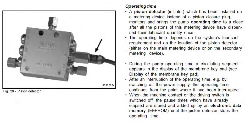
Lincoln Quicklub System Installation Manual for: CAT M Loaders
|
|
|
- Gillian Robertson
- 5 years ago
- Views:
Transcription

1 Lincoln Quicklub System Installation Manual for: CAT M Loaders
2 Contents: I. Introduction 1. System Operation 2. Components II. III. IV. Special Tools System Layout and Design 1. System Drawing 2. Lube Factors Welding Layout 1. Placement 2. Prep and Painting V. Pump Mounting and Wiring 1. Placement 2. Power 3. Routing 4. Testing VI. VII. VIII. Valve Placement and Configuration 1. Line Layout 2. Zone Layout Line Routing Guarding 1. Placement and type 2. Fabrication IX. Purging and Testing X. Programming XI. Trouble-Shooting XII. Additional Information
3 Section I Introduction
4 The Lincoln QuickLub System is the industry standard and covers 95% of all mobile equipment lube systems that Auto-Lube Services, Inc. installs. The systems operate the same regardless of the equipment they are installed upon. While the system layout will vary based upon make and model, the basic system operation principle and type of system components will be identical. This section of the guide will cover system operation and an explanation of the components. As a quick overview, the Lincoln QuickLub system is a 12 or 24-volt electric pump system that operates off of less than 5-amps of DC power. The pump is controlled by an internal timer that has an adjustable off-time. The off-time is the time between run cycles. When the off-time elapses, the run portion of the cycle commences. This is controlled by the proximity switch. Once the proximity switch sends the appropriate number of cycle counts, the controller resets and starts the off-time over again for the next Lube event. The off-time cycle and run cycle together comprise a single lube event. The pump can have 1, 2, 4, 8, and 15-liter reservoirs. For reference, an 8-liter reservoir is just over 2 gallons of grease and should typically last hours of machine run-time before re-filling is required. Section I.
5 Section I.


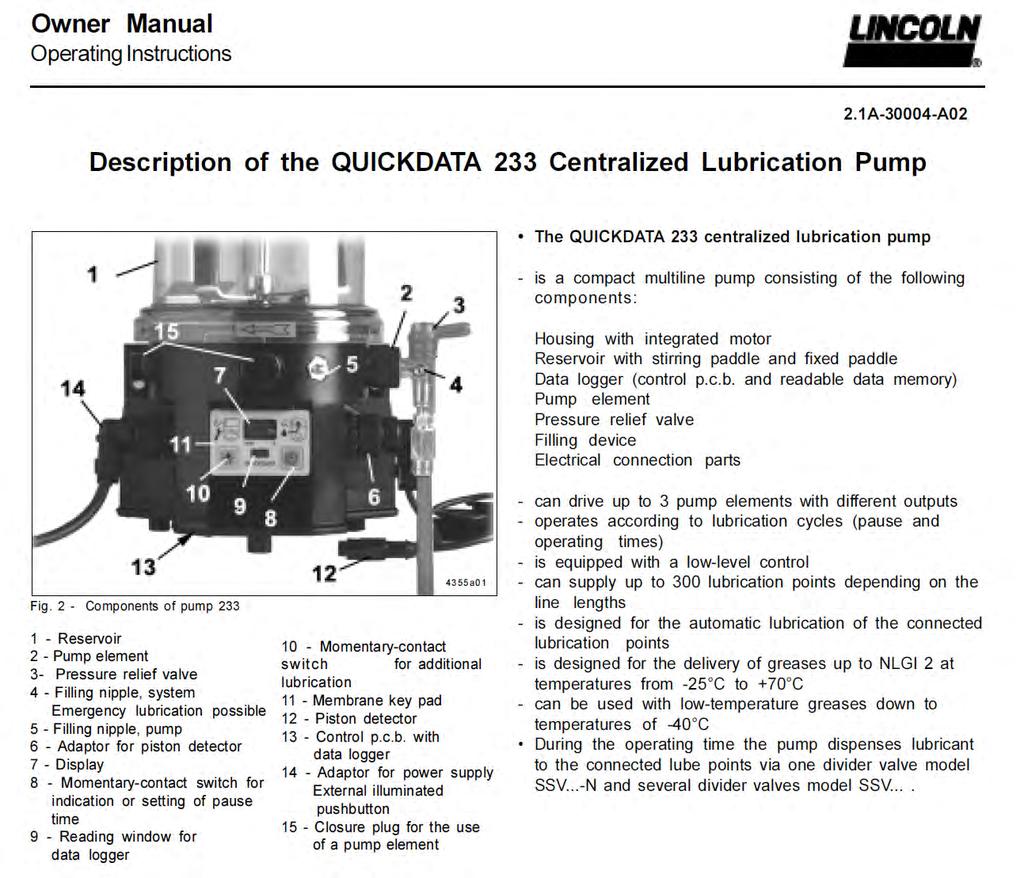
6 Example of 2-liter Pump Example of 8-liter Pump The QuickLub #203 family of pumps is extensive. The #233 data-logger is a sub-category of the #203 family. They come in 12 or 24 DC, or AC variants. Standard pumps come with only timers for on and off operation. Other pumps, like the Data-Logger, have full monitoring and alarm capabilities. Together with a multitude of reservoir options, there is a pump to precisely fit every application. Section I.
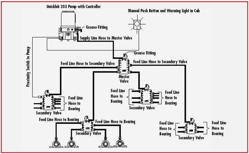
7 The Lincoln QuickLub (SSV) series valves are progressive metering devices. As the pump dispenses grease, the lubricant flows through the valve in a progressive sequence. As each piston in the valves shifts, it opens up a passage allowing the next piston to shift. This continues in a progressive sequence until all of the pistons in that valve have shifted. This ensures that each point gets the pre-determined amount of lubricant. It also ensures, through the sequential operation, that each point gets grease one at a time. This allows the system, via the proximity switch, to monitor flow through the system and detect a blockage. One full cycle of the valve is confirmed by one full cycle (in/out) of the cycle indicator pin. Because the QuickLub valve can be configured for differential proportioning, the system can have different amounts of lubricant dispensed from the primary to the secondary valves. This allows for different proportional amounts of lubricant to certain areas of the machine. As an example, during a normal lube cycle, the system can give times as much grease to an impact zone secondary than a non-impact zone valve. This allows more critical lube points to receive more lubricant during the same lube event. Proportioning within the Lincoln QuickLub system is done through cross-porting. This system uses plugs to divert grease out a given outlet to another outlet. The affect is to double, triple, or even quadruple the amount of lubricant being dispensed to a bearing. Proportioning is an important and critical aspect of the systems. Section I.

8 Quicklub values ensure the right amount grease is delivered to each bearing point according to their requirements No replacement errors possible Precision piston tolerances ensure exact amounts of grease are delivered to each bearing Quick plug in connections throughout entire system, up to 350 bar Proximity switch sends signal back to pump when valve has completed cycle High pressure feedline hose - 4,000 psi Proper system function is monitored by a proximity switch -30 C to +100 C Serviceable at high thermal bandwidth No gaskets or O rings to leak Section I.
9 Cross porting (Divider valve) Section I.

10 Cycle indicator stems on each valve show proper operation of valve. Proximity switch on secondary valve insures that all pins receive grease during each lube event. Section I.
11 Section I.
12 Section I.
13 Section I.

14 Section I.
15 Section I.
16 Section II Special Tools:
17 Special Tools: In addition to the standard hand tools and electric tools possessed and used regularly by each technician, the following tools will be need for this installation. These are tools not regularly stocked on the service trucks and must be placed on the truck prior to leaving the shop for the job site. Note: Due to the infrequent nature and use of these tools, their proper functionality must be tested and confirmed before leaving for the job. The necessary Special Tools are: NO SPECIAL TOOLS REQUIRED FOR THIS INSTALL Section II.
18 Section III System Layout and Design:
19 Right Rear Steering Cylinder: 1:1 Left Rear Steering Cylinder: 1:1 Right Front Steering Cylinder: 1:1 Left Front Steering Cylinder: 1:1 Left Lower Lift Cylinder: 1:1 Right Lower Lift Cylinder: 1:1 Center Support Bearing: 1:1 Left Upper Lift Cylinder: 5:1 Right Upper Lift Cylinder: 5:1 Tilt Cylinder: 1:1 Z-link Pivot: 8:1 Z-link Cylinder: 4:1 Z-link/dog-bone: 4:1 Left Lift Arm: 1:1 Right Lift Arm: 1:1 Upper Center Pivot: 6:1 Lower Center Pivot: 6:1 Rear Axle Front Pivot: 12:1 Rear Axle Rear Pivot: 12:1 Left Bucket Pin: 15:1 Right Bucket Pin: 15:1 Dog-Bone/Bucket Link: 8:1 Lubrication Volume Factors Section III.
20 Zone #2 6-outlet SSV Z-link Cylinder PLUG Z-link Pivot Inlet Z-link dog bone PLUG Dog Bone/Bucket Zone #1 10-outlet SSV Right Lift Arm Rt Rear Steering Cylinder Rt. Front Steering Cylinder Center Support Bearing Right Lower Lift Cylinder Inlet Left Lift Arm Left Lower Lift Cylinder Left Front Steering Cylinder Left Tilt Cylinder Rear Left Rear Steering Cylinder 6-outlet SSV Inlet Zone #4 Lower Pivot Pin 5 6 Upper Pivot Pin PLUG 3 4 PLUG Rear Axle #1 1 2 Rear Axle #2 Zone #3 8-outlet SSV Inlet Inlet 10-outlet SSV Primary 8 Liter 203 Pump Left Upper Lift Cylinder PLUG PLUG Bucket Pin Left Right Upper Lift Cylinder PLUG PLUG Bucket Pin Right PLUG Zone #2 PLUG PLUG Zone # Zone #1 PLUG PLUG PLUG Zone #3 Section III.
21 Section IV Welding Layout:
22 Caution: It is vital and imperative that a welding blanket be used at all times when welding on mobile equipment. Welding slag and splatter can permanently damage windshield glass, light lens, cylinder chrome, and plastic panels. Welding can also burn decals and large areas of painted surfaces requiring large-scale touch-up or re-paint. Pay close attention to detail!! Careless welding practices can cause high and significant damage claims by the customer or dealer. ALWAYS disconnect the battery or Master Switch OFF before welding!!! Section IV.

23 The remote fill block is welded underneath the cab on the left frame member. It is oriented with the ports facing forward, backward, and down. Section IV.
24 The primary mounting block is mounted on the transmission frame brace on the left side of the drive-shaft. It is oriented so that the valve faces the ladder. No other studs are required. Section IV.
25 The rear valve mount is welded on the rear frame just forward of the hydraulic tank. It is adjacent to the zerk manifold for the rear axle. Section IV.
26 The lower center pin lube line needs three (3) studs on the front box frame. The picture to the left shows the bottom most of those three studs. These are for securing this line so that it does not contact the driveshaft. Section IV.
27 The Center valve (house) mount is welded on the right-hand outside of the box frame just behind the front right tire. There will need to be four (4) studs welded in this area to help route the lube lines and proximity wire. Section IV.
28 Right outside view of the front box frame showing the studs necessary for routing the lube lines to the Lift and Steering cylinders Section IV.
29 Left side view of the front box frame showing lube line routing to the steering and lift cylinder lube points. Section IV.

30 Lift Arm/Bucket Pin secondary valve mount is welded on the left Lift Arm just behind the torque tube. There will be 4-5 studs welded from the shoulder pin to the secondary valve for routing the supply lines. There will also be 3-4 studs securing the lube lines going to the bucket pins and across the torque tube. Section IV.

31 The Lift Arm guards are welded nut down to create threaded bosses that the guard will be bolted to. As the guard is held against the machine, the nuts are tack welded in place. The guard is removed and the welding is completed. There will be 6 nuts per side. Section IV.
32 Picture showing the completed Lift Arm guards, Dog-bone guard, and turret rings installed and final painted. Section IV.
33 Turret Rings will be welded on the Lift cylinders to protect the lube inlet from damage. One for each side. Section IV.

34 The Z-lever secondary mount is welded vertically on the Z-lever casting. The guard will be bolted on after final assembly. There will be a total of 6 studs welded on the Z- lever to secure the lube lines. Please see photo for detail. Section IV.
35 Here is the stud underneath the torque tube for running the supply line between the junction block to the Z- lever secondary. Section IV.
36 Detail of the back underside of the torque tube showing the junction block with zerk fitting. This connects the supply line with the Z- lever secondary. There will be 4 studs across the back of the torque tube for routing these lines across. Section IV.
37 Left underside view of the torque tube showing routing of left-hand lines to bucket pins and lift cylinder clevis. Note the strategic location of welded studs. Section IV.
38 Section V Pump Mounting and Wiring: Section V.

39 Section V.

40 CAT 966M Pump location. Located on left side of machine on deck. The lines and wires are routed below the pump using ¼ -20 hardware as through-bolts on the deck. Section V.

41 CAT 972M Pump location. Located on right side of machine on deck. The lines and wires are routed below the pump using ¼ -20 hardware as through-bolts on the deck. Section V.

42 Remote Fill Location. Located on left side of machine below the cab in the center section. The line is routed through the center and beneath the cab. It will come out behind the cab and follow the other line across the deck to the pump. Section V.
43 Section V.
44 Pump Wire Harness Pump Power (+) Always wired to Key-ON circuit. Must be Auxiliary or spare on fuse panel. Must be 10 AMP fuse Only wire to Starter solenoid as a last resort. Pump Power (-) Must be a chassis ground Must pass continuity test Can be connected to pump bracket (only if mounted solid to metal surface) Section V.

45 The power cord passes into the cab through an unused grommet located on the cab floor behind the seat. The plastic dash panel behind the seat will need to be removed. Section V.

46 The power cord Ground (-) is made at the yellow tab just to the left of the fuse panel. This is a ground chassis bolt. Section V.

47 The power cord (+) is connected to the autolube auxilary fuse output. This connection will be made on the back of the fuse panel. It is a 10-1mp circuit. There will be only one wire. Our connection will be spliced in with this. As the electrical fuse panel layout changes periodically, check the fuse panel diagram for the correct fuse. Section V.
48 Section VI Valve Placement and Configuration: Section VI.

49 Zone #1 10-outlet SSV Inlet 6-outlet SSV Inlet Zone #4 Zone #2 6-outlet SSV Inlet Right Lift Arm Rt Rear Steering Cylinder Rt. Front Steering Cylinder Center Support Bearing Right Lower Lift Cylinder Left Lift Arm Left Lower Lift Cylinder Left Front Steering Cylinder Left Tilt Cylinder Rear Left Rear Steering Cylinder Lower Pivot Pin 5 6 Upper Pivot Pin PLUG 3 4 PLUG Rear Axle #1 1 2 Rear Axle #2 Z-link Cylinder PLUG Z-link Pivot Z-link dog bone PLUG Dog Bone/Bucket Zone #3 8-outlet SSV Left Upper Lift Cylinder PLUG PLUG Bucket Pin Left Inlet Right Upper Lift Cylinder PLUG PLUG Bucket Pin Right PLUG Zone #2 PLUG PLUG Zone #4 10-outlet SSV Primary Zone #1 PLUG PLUG PLUG Zone #3 Inlet Liter 203 Pump Section VI.
50 Inlet 10-outlet SSV Primary PLUG Zone #2 PLUG PLUG Zone # Zone #1 PLUG PLUG PLUG Zone #3 Section VI.
51 Zone #1 10-outlet SSV Inlet Right Lift Arm Rt Rear Steering Cylinder Rt. Front Steering Cylinder Center Support Bearing Right Lower Lift Cylinder Left Lift Arm Left Lower Lift Cylinder Left Front Steering Cylinder Left Tilt Cylinder Rear Left Rear Steering Cylinder Section VI.
52 6-outlet SSV Inlet Zone #4 Lower Pivot Pin 5 6 Upper Pivot Pin PLUG 3 4 PLUG Rear Axle #1 1 2 Rear Axle #2 Section VI.
53 Zone #2 6-outlet SSV Z-link Cylinder PLUG Z-link Pivot Inlet Z-link dog bone PLUG Dog Bone/Bucket Section VI.
54 Zone #3 8-outlet SSV Inlet Left Upper Lift Cylinder PLUG PLUG Bucket Pin Left Right Upper Lift Cylinder PLUG PLUG Bucket Pin Right Section VI.
55 Section VII Line Routing:
56 Line routing is critical to a successful installation. It serves two main purposes. First, the proper routing of lube lines ensures the proper connection of all lines within the system in an aesthetic and visually pleasing manner. This also helps with servicing and trouble-shooting as a cleanly routed line is easy to diagnose and repair/replace. Secondly, and possibly more important, proper routing is a form of guarding. A line that is properly routed out of the path of possible damage is, by virtue, protected or guarded. This becomes very critical on all makes and models of machines for the lube lines that are run in the impact zone of the machine. The machine was designed and built without any thought given to the addition of a lubrication system after-market. Routing helps to compensate for this. The pathway of the lube line, the number and style of clamps, the size of the lube line bundle are all critical in ensuring the lubrication system remains undamaged and functional. The aesthetic side of routing brings further value in making the lubrication system appear to be part of the machine. Caution: Improperly routed lines are a leading cause of internal warranties and customer call-backs. These arise form lines that are too long, too short, not clamped adequately, routed in an incorrect location, too much slack at an articulation joint, etc Pay close attention to detail!! Sometimes as little as an inch in placement can make the difference between a lube line lasting or being damaged prematurely. Section VII.

 #252717 hose 5/16")


57 Assembly of Lincoln QuickLinc Hose Stud Fittings Black Par-Flex (Lincoln) # hose 5/16 O.D. x 1/8 I.D. Lincoln # Swivel Inlet Lincoln # Hose nut Lincoln # Hose stud Lincoln # Inlet Section VII.
58 Detail of the supply lines at the primary. These lines connect to Zone #1, #2, #3, and #4 secondary valves. All outputs will be hose stud 90 fittings. The incoming supply line from the pump routes through the deck along with the remote fill line. All other lines bend around and head into the center section. Section VII.

59 Detail of the lube lines and proximity switch wire passing through the center section. This bundle will include the proximity switch wire, supply lines for Zones #1, #2, and #3, Lube lines for the upper and lower center pins, and rear steering cylinder points Section VII.
60 Detail of the lube lines and proximity switch wire on the center section valve. The two rear steering cylinder points will be coming off of the bottom of this valve and will pass through the bundle to the rear chassis. Section VII.

61 Detail of the lube line going to the Center Support Shaft Bearing. NOTE: This should be connected only if it is not part of the parking Brake assembly Section VII.

62 Detail of the lube line going to the Lift cylinder on the right side of the machine. A hose stud 90 and #10181 extension will be necessary for both sides. Section VII.

63 Detail of the lube lines to the lift and steering cylinders on the left side of the machine. Section VII.
64 Detail of the rear secondary valve. The manual lube manifold will connect the two points from this valve to the rear axle lube points. The rear steering points are connected to the center section valve with the proximity switch. The two single outlets will connect through the center section to the upper and lower center pins. Section VII.

65 Detail of the lube line going to the upper center pin. Sometimes this may be ¼ -28 or 1/8 -NPT. Use adapter if necessary. Zip-ties will hold this line in place on the front chassis. Section VII.
66 Detail of the lube line going to the lower center pin. Sometimes this may be ¼ -28 or 1/8 -NPT. Use adapter if necessary. Use the welded studs to secure this line up to the other lines going through the center section. Section VII.

67 Detail of the supply lines for Zone #2 and #3 coming from the front chassis over to the left Lift Arm. While this is not a CAT machine, it shows how little this loop needs to be. With the bucket on the ground, this loop needs only 2-3 inches of extra length. The line will grow as the Lift arms rise. Section VII.
68 Detail of the lube lines at the Lift Arm secondary valve. Here, the supply line for the Z-lever valve runs with the feed-lines towards the torque tube. Section VII.
69 Detail of the lube lines from the Lift Arm secondary valve. Here, the feed-lines for the Lift cylinder clevis and right bucket pin emerge from above the lift cylinder clevis and run to the lift cylinder point and then down the guard to the bucket pin. Section VII.

70 Detail of the lube line at the Lift cylinder clevis. This is identical on both sides. Section VII.

71 These are the feed-lines on the left lift cylinder routing from inside the lift arms to the outside. Note the lines for the right side as they began their route across the underside of the torque tube. Section VII.
72 Detail of the lube lines as they cross the underside of the torque tube. Note the junction block and supply line being routed forward for the Z- lever secondary valve. The lines on the far right are the feed-lines going to the right side lift cylinder clevis and right bucket pin. Section VII.
73 Detail of the supply line as it crosses from the underside of the torque tube to the Z-lever. Note the clamp location and the very small amount of loop necessary for this articulation joint. Section VII.
74 Detail of the lube lines at the Z-lever secondary. There are four (4) feedlines and one supply line in this area. Note the clean routing and the guard placement. Section VII.

75 Detail of the lube lines on the Z-lever going to the Dog-bone. It is essential that both of the dog-bone feed-lines come off of the back of the Z-lever and curl to the top of the dog-bone. The rear fitting will loop directly into the rear inlet. The front lube line will follow the same route and emerge at the top of the dog-bone and then pass through the guard to the front inlet. Section VII.
76 Section VIII Guarding:
77 Each and every lubrication system has specific needs for protection that require some sort of consideration be made for the security of the lube valves, lines, and fittings. Due to the nature of how the equipment is being used and the environment that it will be working in presents many challenges regarding protecting the critical system components. These challenges may require guarding that is either standard or custom fabricated. This section will cover the standard guarding used on this make and model to address the most common guarding considerations. These considerations may include: Wet digging (water, mud, corrosion, etc ) Rocky digging (physical damage, abuse, etc ) Clearing (lines being torn off by branches) Burn piles (melted or damaged lines and valves) Dusty environments (fine dust that enters bearings quickly) Caution: Improper or insufficient guarding are leading causes of internal warranties and customer call-backs. These arise from lube lines being broken prematurely due directly to guards not adequately covering the lube lines. At times, the guard can actually cause the lube line breakage due to interference with the lube line during articulation of the machine. Pay close attention to detail!! Section VIII.
78 Caution: It is vital and imperative that a welding blanket be used at all times when welding on mobile equipment. Welding slag and splatter can permanently damage windshield glass, light lens, cylinder chrome, and plastic panels. Welding can also burn decals and large areas of painted surfaces requiring large-scale touch-up or re-paint. Pay close attention to detail!! Careless welding practices can cause high and significant damage claims by the customer or dealer. ALWAYS disconnect the battery or Master Switch OFF before welding!!! Section VIII.

79 Standard 60 guards will be used. They will be cut back to the first set of bolt tabs. This will leave the segmented potion of the guard for use as a guard on the dog-bones. (See further pictures) Section VIII.

80 Turret Ring guard welded to the end of the Dogbone. Segmented ends of 60 guards are welded together to create a Dogbone guard. Approximately 18 in length. This is welded directly to the top of the dog-bone. Section VIII.

81 Turret Ring will be welded on the bucket end of the dog-bone to protect the lube inlet from damage. Only one required. Segmented ends of 60 guards are welded together to create a Dogbone guard. Approximately 18 in length. This is welded directly to the top of the dog-bone. Section VIII.

82 Segmented ends of 60 guards are welded together to create a Dogbone guard. Section VIII.

83 Completed guarding package showing Lift arm Guards and Dogbone guard installed and painted Section VIII.
84 Right side of machine showing Boom Arm guard made from cutting a standard 60 guard. The nuts are welded to the machine as bosses. The bolts then attach the guard to the machine Section VIII.
85 The cut 60 guard will entirely cover the lube line up to the fitting. This will be left exposed for ease of service. Section VIII.
86 The Z-lever valve is welded to the inset of the bottom of the Z-Lever. It is protected from damage by the valve guard shown in this photo. This guard is assembled onto the valve and then final painted. Section VIII.

87 Turret Rings will be welded on the Lift cylinders to protect the lube inlet from damage. One for each side. Section VIII.
88 Section IX Purging and Testing:
89 Once the lubrication system has been properly installed, it must be completely purged of air and contaminants with the proper lubricant. This process pre-fills all of the lines and valves in preparation for proper functioning of the lube system. It is also the procedure for finding and diagnosing problems that may exist with the system, its components, or the installation. This is one of the most critical steps in a proper and successful installation. At this point, the purging must be done using a specific procedure. Any deviation from the procedure may result in a misdiagnosed problem or unsuccessful installation. The following steps must be done in order and to the full degree of completion. Caution: Purging large amounts of air through a divider valve may cause the divider valve to quit working properly. The air can cause the valves to cycle very rapidly and cycle them out of sequence. Once out of sequence, the valve can only be repaired by disassembly and proper cycling with lubricant. Caution: The use of unauthorized or incorrect lubricants can cause the lubrication system not to function properly. Lubricants with NLGI ratings over #2 (#1 in cold weather) are too thick and will result in poor pumping performance and resulting ER message faults. Lubricants with Moly above 3% or total solid content above 5% will clog the system over time causing the pump and valves to seize during operation resulting in numerous faults. This may further result in the warranty being voided. Section IX.
90 Step-by-Step Purging Process: 1. Ensure that the system is completely assembled and all lines are terminated 2. Clean the grease gun before connecting to clear nozzle of contaminants 3. Disconnect the supply line from the pump; back purge supply line from primary valve. 4. Re-connect after purging 5. Disconnect all secondary supply lines from secondary valves. Purge supply lines from primary valve. Re-connect after purging. 6. Purge each secondary zone one at a time ensuring that the indicator pin moves freely 7. Once each valve (zone) is purged, wipe away any excess grease or mess. 8. After all valves and lines have been purged, walk around machine to inspect for leaks 9. Inspect the pressure relief for signs of over-pressure. 10. If any blockages or problems exist; refer to the Trouble-shooting section of this guide 11. Once the system has been successfully purged, the pump may be energized 12. Programming of the pump is handled in the programming section of this guide. 13. Initiate a manual lube event at the pump 14. Walk around the machine and inspect for proper functioning of the lube system while also verifying indicator pins cycling and the lack of any leaks 15. Once the system has been cycled manually for 6-8 cycles, the system must be run in auto mode. 16. Set the off-time timer to the minimum time setting (4 minutes). Allow the system to count down, cycle, and successfully reset. 17. Refer to the Trouble-shooting section of this guide for any problems 18. This successfully concludes the purging and testing part of the installation Section IX.
91 Notice: Test the Machine!! In order to successfully complete the installation, you must thoroughly test the machine. This means articulating the machine in every direction in order to find any instances where a line, guard, or component may be impacted, damaged, or removed. Once the line or component is damaged, it must be replaced, re-installed, and tested again. It is imperative to anticipate and slowly test areas where interference may be possible. To best test the machine, first identify the areas where interference might be possible. Then, articulate the machine slowly and watch for impact or potential damage. Once this has been eliminated, inspect the machine again for any other areas where damage might have been undetected. Section IX.
92 Section X Programming:
93 The Lincoln Data-Logger #233 pump is a very simple unit to program. The pump uses the controller for off-time settings. The proximity switch (cycle switch) is used to set the run duration or portion of the lube event. The program allows you to adjust the off-time timer settings in minutes and hours, the number of cycles from the proximity switch before resetting the pump, and the style of fault contact closure desired. Note: To fully understand the functioning of the lubrication system, refer to the system introduction covered in Section I of this Guide. The next few pages of the guide give a detailed explanation of the programming function and sequence for the Lincoln #233 pump controller. For a quick reference or review of the proper programming for this make and model, refer to the last page of the section. Here, the quick reference guide will instruct you on the proper program that should be entered for this specific make and model. Section X.
94 Section X.
95 Section X.
96 Section X.
97 Section X.
98 Programming Quick Reference Sheet 1. Press and Hold red & green buttons until P1 appears 2. P1 is hours of Off-time. Set value at 0 3. Press green button to change value, or red button to move to next page 4. P2 is minutes of Off-time. Set value at 5. P3 is the # of cycles per lube event. Set value at 1 6. P4 is the switching of the alarm contact. Set value to NO for normally open 7. At the P- symbol, press green button to save program and enter run mode. 8. Press and hold green button for 4 seconds to initiate a manual lube cycle and diagnostic test Note: The system alarm time, the time the pump will run waiting for the programmed number of cycles switch counts to be satisfied, is fixed at 30 minutes at the factory. After 30 minutes without the pre-determined number of cycle counts, the system will go into ER fault. This cannot be changed within the program. Section X.
99 Section XI Trouble-Shooting:
100 The QuickLub system, like any machine, can and will have issues and malfunctions. These malfunctions are detected by the system during its normal diagnostic checks. These checks occur during the normal operations of the system. Any condition that causes a break in the normal operation of the system will result in a fault condition occurring. During a fault, the system will suspend normal operation until the fault is remedied and the fault is cleared. While in fault, the system can be run manually using the green pushbutton on the keypad to initiate a manual lube event. This can be done for any fault at any time. However, if the fault cause is not remedied, the fault condition will return during the operating cycle. The system will not run automatically until this condition is remedied. Discovering the cause of the fault can be rather difficult depending upon what type of fault exists. Certain faults cannot be fixed in the field and require the pump be sent in for rebuild. In the case of a low-level or LL fault, the solution is intuitive and can be easily fixed. As it usually is caused by lack of grease in the reservoir, refilling the reservoir and acknowledging the fault is the remedy. An ER fault, on the other hand, is a much more complex situation that can have a multitude of causes. If the correct cause is not identified, the system will continue to perform inadequately. For the purposes of this manual, we will focus mostly on the ER fault. Section XI.
101 Typical error messages that will be shown on the Lincoln #233 Data-Logger pump display. These will be the fault indications during a lube system error or malfunction Section XI.

102 LL flashing in display indicates low level in grease reservoir. Corrective Action: Refill reservoir, push and hold green button on pump for 4 seconds to clear the fault. Section XI.
 Bad pump element Air in the system Air in the")
103 E R flashes in display when the pump fails to receive the correct number of cycle counts from the proximity switch within the 30 minute alarm time. This may be caused by one of the following: Plugged lube line Bearing not taking grease Faulty Pump Faulty Proximity Switch Leaks Trash in the Valve(s) Bad pump element Air in the system Air in the reservoir Incorrectly installed hose fitting Faulty pressure relief Section XI.
104 Corrective Action: Cycle each valve at grease fitting to find blocked line and repair blockage. If all valves cycle properly, check output of pump element, if insufficient replace element. Check proximity switch wire and proximity switch operation. The indicator light on the proximity switch is a visual cue to its proper functioning Section XI.

105 Note: The pump will never clear its own faults. It will not resume normal operation until the fault is cleared. The pump must be run through a manual cycle in order for it to run its diagnostic check and clear the fault. Section XI.
106 Section XI.

107 Pressure relief functioning. Typically, the pressure relief is preset at the factory at around 3,800psi. However, the relief can be adjusted in the field by removing the rubber cap and adjusting the socket head screw underneath to increase the pressure threshold. Section XI.


108 Grease coming from pressure relief indicates a blockage in the system. This can be due to several factors, including a faulty pressure relief. Corrective Action: Manually cycle valves at grease fitting to find location of blockage. Repair blockage or readjust/replace pressure relief. Manually cycle again to check. Section XI.

109 Note: this is the only reason for the ER message. While there are a multitude of causes for this condition. The pump generates the ER fault simply because it did not receive the cycle signal from the proximity switch within this 30 minute monitoring or alarm time. Section XI.
110 Trouble-Shooting the ER Fault: While the meaning of the ER fault is very simple. The causes can be very complex and misleading. This, oftentimes, leads to it being misdiagnosed resulting in a return trip and/or an unresolved fault condition. This fault condition continues to confuse and complicate trouble-shooting measures on both new and old installations. The purpose of this section is to describe the ONE correct method of trouble-shooting this fault condition. The goal here being to quickly identify the correct cause through a process of elimination. This process will identify the cause by eliminating possible culprits one at a time. As this process proceeds, the cause will become obvious to even the relatively untrained mechanic. Taking this process out of order or proceeding only partially WILL result in an improperly diagnosed fault cause and an unresolved fault condition. You MUST follow these steps through to the cause. There are no short-cuts. In most cases, the ER fault, while a system fault, is created by something wrong with the machine or a lubricant problem. Stay patient, by generating the fault, the system is doing its job. Through the process, the system will tell you and lead you to the problem. Patience is Key!!! Section XI.
111 Trouble-Shooting the ER Fault: A Step-by-Step Guide Step 1: Look at the pressure relief. Is Grease coming out? If yes, go to Step 9. If no, go to Step 2 Step 2: If no grease is at pressure relief, disconnect main grease line at pressure relief and manually cycle the pump. If no grease check the reservoir for air and proceed to Step 3. If there is grease coming out, proceed to Step 4 Step 3: If reservoir is full with appropriate grease, verify that the pump is running. If not, check check ground and voltage to pump. Next, remove and inspect pump element. Replace the pump element if necessary. Reconnect and run system Step 4: If grease is being pumped out, check the pressure with a pressure gauge. Another method is to hold your finger over the output of the pump element. If you feel the grease being dispensed but sucked back in, the element is bad. Replace the element, reconnect the system, and test. Step 5: If the element tests fine, the problem is not a blockage. That would cause the relief to discharge. Verify, at this point, that the system is physically cycling. The problem surrounds the pump receiving the signal from the proximity switch. Verify, at the pump, that the proximity wire is firmly connected. Next, trace the proximity wire to the switch. Inspect for frays, breaks, or cuts. Repair as necessary. Step 6: If wire is fine, run the system manually and inspect the proximity switch indicator light. The light will turn on and off as the valve cycles. If the valve cycles, but the switch light does not, replace the proximity switch. If the light does cycle with the valve, the problem may then either be the PCB board in the pump or the proximity switch. Section XI.
112 Trouble-Shooting the ER Fault: A Step-by-Step Guide Step 7: First, remove the proximity switch from the valve. Cycle the pump manually. Use an Allen key to actuate the proximity switch. As you slowly insert the Allen key, verify that the light turns on and off. If the pump shuts off, the problem is not the pump or the switch, but the valve. IMPORTANT the proximity switch must not be installed in the outlets furthest from the valve inlet. This will short stroke the switch and cause a fault. Otherwise, make sure that the switch is installed correctly in the valve. Change the valve as needed. Step 8: If the pump does not shut off, the problem is on the PCB board. Replace the PCB board in the pump. Test the system Step 9: Grease coming out of the pressure relief indicates a system restriction. Cycle each secondary valve with a grease gun. Do not do this with a pneumatic gun as you will not be able to feel the resistance in each line. Do not try to cycle the primary valve as grease will only come out of the pressure relief confirming what you already know. As you test each valve, you will encounter one valve that either does not cycle, or cycles with a great amount of resistance. Remember the pressure relief is set at 3,800 psi. Anything over that pressure will cause it to discharge. Step 10: Now that you have identified the blocked or slow valve, you have to determine the cause. Inspect all of the outlet lines from that valve. Look for the one that is under back-pressure. It will be extended and will not wiggle in the outlet coupling. Step 11: Once you have identified the line with the restriction, disconnect it from the bearing. Cycle the system again. If OK, the bearing is the issue. If not, go to Step 12. Section XI.
113 Trouble-Shooting the ER Fault: A Step-by-Step Guide Step 12: Step 13: Step 14: Step 15: Step 16: If the line is still blocked, reconnect the line to the bearing. Disconnect the same line at the valve and cycle again. If OK, the line is the problem. Repair or replace as necessary. Test the system If the blockage remains, disconnect all lube lines from the valve. Manually cycle the valve. If still blocked, the problem is the valve. Replace valve and test. If the valve was the culprit, the cause may still not be known. Inspect the lube valve Look for signs of contamination. If yes, inspect all other valves and purge system again to clear contaminants. Also, check the reservoir for contamination. If no contamination is evident, inspect the valve for incorrect fittings. An incorrect inlet installed in a valve outlet can cause a bypass that can fool a proximity switch. If yes to incorrect fittings, check all other valves in the system. If in the course of the trouble-shooting, no blockage or restriction was found then, and only then, should the pressure relief be the suspected cause. Re-adjust or replace as necessary. Note: there is only one reason for the ER message. While there are a multitude of causes for this condition. The pump generates the ER fault simply because it did not receive the cycle signal from the proximity switch within the 30 minute monitoring or alarm time. Section XI.
114 Trouble-Shooting the ER Fault: A Step-by-Step Guide Important!! ER faults can be caused by a multitude of reasons. Sometimes, phantom faults can occur on cold mornings or evenings when the grease viscosity increases with dropping temperatures. This causes the system pressure to increase above the setting on the pressure relief. Other times, a fault may occur in winter due to the grease being too high a viscosity. It is always recommended that the customer switch from NLGI #2 to NLGI#1 during winter months. Important!! ER faults can be caused by contamination. Removing a reservoir lid for filling or using improper filling techniques can allow contamination to enter the system. The use of greases with MOLY contents higher than 3% or solid contents higher than 5% can cause blockages as these concentrations react with the system the same as contaminants. The result will be an ER fault due to contamination Section XI.
115 Contamination Control: Proper Reservoir Filling Always fill the reservoir from the included fill port. Always clean the nozzle before filling the reservoir Always completely fill the reservoir until grease comes out the over-flow tube Never half or partially fill the reservoir Never allow the reservoir to run out of grease Always maintain high level in the reservoir. Fill the reservoir often. Never remove the reservoir to fill it Never fill the reservoir with grease combined from two or more empty drums Never pump air into the reservoir. If possible, try to cycle the pump at least once while filling to mix the grease Never combine one or more different types of grease in the reservoir Never make a top fill port on a lidless reservoir. Section XI.
116 Further Trouble-shooting Considerations and Hints Section XI.
117 Section XI.
118 Note: The pump element should be replaced only after verifying that it is indeed bad. A pressure gauge or a timer can assist with this diagnosis. Be aware that low pressure can be an indication of valve bypass or a leak as well. Also note that a long cycle time can be caused by leaks, improper lubricant, and cold temperatures. Do the proper trouble-shooting!! Section XI.
119 Section XII Additional Information:

120 When mounting a pump behind the cab of any machine, leave enough room for the operator to break the glass and escape from the cab in the event of an emergency. The back glass on all Operator cabs are Escape Hatches for the purposes of an Emergency Exit! Section XII.
121 Section XII.
122 Contacts: Auto-Lube Services, Inc Pecan Street P.O. Box 639 Loganville, GA Ph: (678)
Owner s and Maintenance Manual for: Lincoln QuickLub Systems
 Owner s and Maintenance Manual for: Lincoln QuickLub Systems Contents: I. Introduction 1. System Operation 2. Components II. Pump Mounting and Wiring 1. Power 2. Testing III. Purging and Testing IV. Programming
Troubleshooting of the LubeTech Grease System
 Troubleshooting of the LubeTech Grease System February 2009 The LubeTech grease system is designed to be a preventative maintenance system that will extend the life of your bearings that are connected
Automated Lubrication System
 Automated Lubrication System Installation/Operator Instructions Case IH RBX2 Series Baler Contents Pages Introduction 3 Preparation 4 Bill of Material 5 Component Appendix 6-9 System Operation 10 Valve
Automated Lubrication System
 Automated Lubrication System Operator s Guide Lexion 700 Series Combine Rev. 1, 7/11, CWA Contents Pages Introduction 3 Component Appendix 4-6 Glossary f Terms 7-8 System Operation 9 Valve Operation 10-11
AGCO Massey Ferguson Combine Models 8780, 9690, Lincoln Automatic Lubrication System Installation Instructions
 AGCO Massey Ferguson Combine Models 8780, 9690, 9790 Lincoln Automatic Lubrication System Installation Instructions System Overview Thank you for purchasing the Quicklub On Board Grease System for your
John Deere R Series Sprayer Lubrication System Installation Guide
 John Deere R Series Sprayer Lubrication System Installation Guide 1 Contents Pages Preparation/Installation Overview 3 Introduction 4 Purging Instruction 5 Divider Valve Operation 6 Components Glossary
SD Bendix M-21 and M-22 AntiLock Modulator Assembly DESCRIPTION M-21 MODULATOR M-22 MODULATOR
 SD-13-4793 Bendix M-21 and M-22 AntiLock Modulator Assembly CONNECTOR DELIVERY (CAST-IN ID #2) (CAST-IN ID #3) DELIVERY (CAST-IN ID #2) (CAST-IN ID #1) DELIVERY DELIVERY (CAST-IN ID #1) CONNECTOR MOUNTING
Operation and service manual
 Operation and service manual SKF Multilube SKF Multilube Central lubrication system Table of contents General system description... 1 Safety instructions... 1 General information on centralized lubrication
Click Here for Printable PDF File. CHAPTER 3 - BASIC INFORMATION for PERFORMING HYDRAULIC SYSTEM MAINTENANCE
 HWH Online Technical School Lesson 1: Introduction to Hydraulics Chapter 3 - "BASIC INFORMATION for PERFORMING HYDRAULIC SYSTEM MAINTENANCE" (Filename: ML57000-012-CH3.DOC Revised: 22APR16) Click Here
Automated Lubrication System
 Automated Lubrication System Installation/Operator Instructions John Deere STS Combine Models 9660, 9760, 9860 Dtd.081506 1 System Overview Thank you for purchasing the Quicklub Combine. On Board Grease
INSTALLATION MANUAL - v4
 I-LOCKTM COUPLER INSTALLATION MANUAL - v4 SPECIAL NOTE Your new Wedgelock Coupler fitted with the I-LOCK TM Safety Device requires the installation of a third hydraulic line - please follow the instructions
 Operation and Maintenance Manual http://www.torsionx.eu Use the MaxDrv Series Square Drive Torque Wrench Model.75, 1, 3, 5, 8, 10, 20, 25, 35, 50 to install and remove threaded fasteners requiring precise
IBT Series Square Drive Torque Wrenches
 IBT Series Square Drive Torque Wrenches Operation and Maintenance Manual Model.75, 1, 3, 5, 8, 10, 20, 25, 35, 50 http://www.torsionx.com Use the IBT Series Square Drive Torque Wrenches Model.75, 1, 3,
Automated Lubrication System
 Automated Lubrication System Installation/Operator Instructions John Deere STS Combine Models 9660, 9760, 9860 Dtd.020405 1 System Overview Thank you for purchasing the Quicklub Combine. On Board Grease
MODEL SCA Installation and Operation Manual Important:
 MODEL SCA Installation and Operation Manual Important: This manual contains specific cautionary statements relative to worker safety. Read this manual thoroughly and follow as directed. It is impossible
Models CHASSIS LUBE ELECTRIC GREASE PUMP Series "C" - 13C MAY FORM Page. Section - Q3
 Models 94422 CHASSIS LUBE ELECTRIC GREASE PUMP Series "C" MAY - 2004 FORM 403467 Section - Q3 Page - 13C 9.00" (229 mm) 13.75" (350 mm) 0.35" (9mm) Mounting Holes 4.76" (121 mm) 9.84" (250 mm) Do not use
Models CHASSIS LUBE ELECTRIC GREASE PUMP Series "C" - Q3. MAY FORM Section
 Models 94822 CHASSIS LUBE ELECTRIC GREASE PUMP Series "C" - Q3 MAY - 2004 FORM 403468 Section Page - 14B 13.00" (330 mm) 17.72" (450 mm).35" (9 mm) Mounting Holes 4.72" (120 mm) 9.84" (250 mm) Figure 1
Thermo-Bob 1 Installation Manual: Kawasaki Concours
 Thermo-Bob 1 Installation Manual: 1986-2006 Kawasaki Concours This is a basic guide for installing the Thermo-Bob 1 on a Kawasaki ZG-1000 Concours. The bike used in the following photos was a 1995 year
 Page 1 of 29 Section 04-05: Suspension, Computer Controlled 1997 Town Car Workshop Manual DIAGNOSIS AND TESTING Procedure revision date: 05/16/2000 Suspension, Computer Controlled Inspection and Verification
Hydro-Max Hydraulic Brake Booster and Master Cylinder. Technical Manual
 Hydro-Max Hydraulic Brake Booster and Master Cylinder Technical Manual * 5+0 Important Service Notes The information in this publication was current at the time of printing. The information presented in
LC I LIPPERT COMPONENTS HYDRAULIC FULL WALL SLIDEOUT SYSTEM OPERATION AND SERVICE MANUAL
 LC I LIPPERT COMPONENTS HYDRAULIC FULL WALL SLIDEOUT SYSTEM OPERATION AND SERVICE MANUAL TABLE OF CONTENTS SYSTEM...... 3 Warning...... 3 Description..... 3 Prior to Operation... 4 4 OPERATION... Main
BASIC BRAKE SYSTEM GROUP 35A 35A-1 CONTENTS GENERAL DESCRIPTION... 35A-3 BASIC BRAKE SYSTEM DIAGNOSIS 35A-6
 35A-1 GROUP 35A BASIC BRAKE SYSTEM CONTENTS GENERAL DESCRIPTION......... 35A-3 DIAGNOSIS 35A-6 INTRODUCTION..................... 35A-6 DIAGNOSTIC TROUBLESHOOTING STRATEGY......................... 35A-6
 Operation and Maintenance Manual Model.75,, 3, 5, 8, 0, 0, 5, 35, 50 http://www.torsionx.com Use the MaxDrv Series Square Drive Torque Wrench Model.75,, 3, 5, 8, 0, 0, 5, 35, 50 to install and remove threaded
Automotive Application ET01 Software Revision A 12/06
 Automotive Application ET01 Software Revision A 12/06 INTRODUCTION... 2 FUNCTIONAL DESCRIPTION... 3 INSTALLATION... 4 COMPONENT PLACEMENT... 4 PLUMBING AND WIRING... 5 MSBC OPERATION (ET-01)... 14 TIMED
Model CHASSIS LUBE ELECTRIC GREASE PUMP Series "C"
 Model 94222 CHASSIS LUBE ELECTRIC GREASE PUMP Series "C" Indicates change MAY - 2004 FORM 403466 Section - Q3 Page - 12B 7.75" (197 mm) 12.6" (321 mm) 0.35" (9 mm) Mounting Holes 4.85" (123 mm) 8.85" (225
Automated Lubrication System
 Automated Lubrication System Installation/Operation Manual Case IH Combine Models 2344, 2366, 2377 and 2388 Revised 08-09-06 1 System Overview Thank you for purchasing the Quicklub On Board Grease System
Farval. Dualine Installation System Start-Up. Bulletin DL300 BIJUR DELIMON INTERNATIONAL
 Farval Dualine Installation System Start-Up Bulletin DL300 BIJUR DELIMON INTERNATIONAL 2685 Airport Road Kinston, NC 28504 Tel. 800-227-1063 Fax: 252-527-9232 website: www.bijurdelimon.com DC1-1 SECTION
16000SIII Automatic Grease System
 Manual # 99905495 16000SIII Automatic Grease System Effective 20120716 IOWA MOLD TOOLING CO., INC. PO Box 189 Garner, IA 50438 Tel: 641-923-3711 FAX: 641-923-2424 Website: http://www.imt.com Copyright
Wiring diagrams on page 29 are for reference only. For detailed vehicle wiring refer to Navistar documents.
 1 10/2014 REV 7 !!Attention!! Before performing diagnostics: Wiring diagrams on page 29 are for reference only. For detailed vehicle wiring refer to Navistar documents. Check for Fault Codes using the
Hydro-Sync Slide-Out System
 Hydro-Sync Slide-Out System SERVICE MANUAL Rev: 08.14.2018 Hydro-Sync Slide-out System Service Manual TABLE OF CONTENTS Safety Information 3 Product Information 3 Operation 4 Extending Slide-Out Room 4
Modulating Furnace Information. Warning on Meter Setting - Read First!
 Modulating Furnace Information Pressure Transducer Pressure DC Volts 0.00" 0.25 0.20" 0.63 0.25" 0.72 0.30" 0.82 0.35" 0.91 0.40" 1.00 0.45" 1.09 0.50" 1.19 0.55" 1.28 0.60" 1.38 0.65" 1.47 0.70" 1.56
SOME BASICS OF TROUBLESHOOTING
 SOME BASICS OF TROUBLESHOOTING DICK RANDALL I decided to pull these ideas together because I have spent plenty of hobby time figuring out things that did not work or that needed repair. This process and
John Deere R4045 Sprayer Wet/Dry Lubrication System Installation Guide
 John Deere R4045 Sprayer Wet/Dry Lubrication System Installation Guide 1 Contents Pages Preparation/Installation Overview 3 Introduction 4 Purging Instruction 5 Divider Valve Operation 6 Components Glossary
MODEL NUMBER: MEDIUM DUTY ONBOARD AIR SYSTEM
 MODEL NUMBER: 10003 MEDIUM DUTY ONBOARD AIR SYSTEM IMPORTANT: It is essential that you and any other operator of this product read and understand the contents of this manual before installing and using
Trouble Shooting Manual Progressive Systems
 1 INTRODUCTION The information contained in this manual provides insight in how a progressive grease distribution system works and how to trouble shoot a progressive system. 2 OPERATING PRINCIPLE Any pump
HexPro Series Low Profile Wrenches
 HexPro Series Low Profile Wrenches Operation and Maintenance Manual Model 2HP 4HP 8HP 14HP 30HP www.torquetoolsinc.com Use the HEXPRO Series Low Profile Wrenches Model 2HP 4HP 8HP 14HP 30HP to install
Class 5 to 7 Truck and Bus Hydraulic Brake System
 Class 5 to 7 Truck and Bus Hydraulic Brake System Diagnostic Guide 2nd Edition www.bosch.us Important Service tes The information in this publication was current at the time of printing. The information
OPERATORS MANUAL/INSTRUCTIONS/PARTS & SERVICE FOR MANUAL & ELECTRIC
 OPERATORS MANUAL/INSTRUCTIONS/PARTS & SERVICE FOR MANUAL & ELECTRIC TABLE OF CONTENTS SAFETY DELIVERY INSPECTION OPERATION 4 MAINTENANCE 5 TROUBLE SHOOTING 5 PARTS 6-15 Frame Scissor Assembly 6-7 Thrust
RUFNEX Series Low Profile Wrenches Operation and Maintenance Manual
 RUFNEX Series Low Profile Wrenches Operation and Maintenance Manual http://www.torsionx.com Use the RUFNEX Series Ultra-Low Profile Wrenches to install and remove large bolts that have minimal wrench clearance.
Low Profile Wrenches Operation and Maintenance Manual
 Low Profile Wrenches Operation and Maintenance Manual http://www.torquetoolsinc.com Use the HEXPRO Series Low Profile Wrenches Model 2HP 4HP 8HP 14HP 30HP to install and remove large bolts that have minimal
OWNER S TECHNICAL MANUAL
 OWNER S TECHNICAL MANUAL 2.5kg Grease Kit 6336 Description The Champion 6336 2.5kg grease kit is a manually operated, spring powered grease kit that comes complete with a hand piece. It is designed to
Control System. Part B, Section 1. This section covers the following unit configurations. Model Voltage 1, 2 Pump Piston (E, F, or G)
") Part B, Section 1 This section covers the following unit configurations. Model 3100 3400 3500 Voltage 1, 2 Pump Piston (E, F, or G) Manifold 4-Port (A) 6-Port (B or C) Control UniScan (1) B 1-0 B 1-1 Section
Part B, Section 1 This section covers the following unit configurations. Model 3100 3400 3500 Voltage 1, 2 Pump Piston (E, F, or G) Manifold 4-Port (A) 6-Port (B or C) Control UniScan (1) B 1-0 B 1-1 Section
VARNA Products 15 GPM (57 LPM) Prelube Kit for MTU 4000 Series Marine Engines
 Prelube Kit for MTU 4000 Series Marine Engines") VARNA Products 15 GPM (57 LPM) Prelube Kit for MTU 4000 Series Marine Engines Installation and Users Manual For the following Prelube Kits: VARNA Products P/N 6423 Kit for 208 VAC 3 Phase VARNA Products
VARNA Products 15 GPM (57 LPM) Prelube Kit for MTU 4000 Series Marine Engines Installation and Users Manual For the following Prelube Kits: VARNA Products P/N 6423 Kit for 208 VAC 3 Phase VARNA Products
40041 Heavy Duty ADA System with Booster Bracket for JK Heavy Duty ADA System with Booster Bracket for 2012 to Current JK
 40041 Heavy Duty ADA System with Booster Bracket for 2007-2011 JK 40044 Heavy Duty ADA System with Booster Bracket for 2012 to Current JK 40049 Heavy Duty ADA System Universal for all vehicles (booster
DTC P0A04 - Open Wiring Fault
 DTC P0A04 - Open Wiring Fault Orion Product Orion BMS [Original] (24-180 Cell) Orion BMS 2 (24-180 Cell) Orion JR (16 Cell) Fault Supported YES YES YES FAULT DESCRIPTION This fault is a serious code that
INSTALLATION INSTRUCTIONS
 INSTALLATION INSTRUCTIONS BIG ROTOR / CALIPER RELOCATION FRONT KITS SUM-BK1422, BK1423, BK1424 1999-2006 GM 1/2 Ton Trucks & SUVs Thank you for choosing SUMMIT RACING for your braking needs. Pleases take
EVAP system, servicing
 Page 1 of 65 20-130 EVAP system, servicing EVAP system components 1 - Cap nut 10 Nm 2 - Cover 3 - Stud For EVAP canister 15 Nm 4 - Sealing piece 5 - Bleed line To EVAP canister purge regulator valve -
Woosh GSM CD Kit Fitting Guide
 Woosh GSM CD Kit Fitting Guide Important: For your own safety you must read this manual before attempting to fit any part of the motor kit to your bike. You must also ensure that you fit the kit in strict
Mopar 8 3/4 & 9 3/4 (Dana) Installation Instructions Rear Disc Conversion
 Installation Instructions Rear Disc Conversion") Mopar 8 3/4 & 9 3/4 (Dana) Installation Instructions Rear Disc Conversion This kit is for either Mopar 8 ¾ or Mopar 9 ¾ (Dana). This kit is designed to work with axles with either GM 5 x 4.75 Bolt Pattern
Mopar 8 3/4 & 9 3/4 (Dana) Installation Instructions Rear Disc Conversion This kit is for either Mopar 8 ¾ or Mopar 9 ¾ (Dana). This kit is designed to work with axles with either GM 5 x 4.75 Bolt Pattern
DIAGNOSTIC TROUBLESHOOTING INDEX
 DIAGNOSTIC TROUBLESHOOTING INDEX Curtis Industries, LLC. 111 Higgins Street Worcester, MA 01606 Telephone: (508) 853-2200 Fax: (800) 876-9104 www.snoproplows.com TROUBLESHOOTING INDEX - BY PROBLEM Section
INSTALLATION INSTRUCTIONS
 INSTALLATION INSTRUCTIONS Disc Brake Spindle Kit SUM-BKA2447 1964-72 A-BODY 1967-69 F-BODY 1968-74 X-BODY Thank you for choosing SUMMIT RACING for your braking needs. Please take the time to read and carefully
TIP SHEET T0937. Installation Tips For RS00/PS00 + ADS-TBSL-PL + SPDT
 Installation Tips For RS00/PS00 + ADS-TBSL-PL + SPDT TIP SHEET T0937 Thank you for purchasing your remote start from MyPushcart.com - an industry leader in providing remote starts to do-it-yourself installers
PowerLevel s e r i e s
 Owner s Manual Hydraulic Leveling CONTENTS Introduction Operation Control Panel Automatic Leveling Manual Leveling Retracting Jacks Remote Operation Care & Maintenance Troubleshooting Error Codes 1 2 2
INSTALLATION INSTRUCTIONS
 INSTALLATION INSTRUCTIONS BIG ROTOR / CALIPER RELOCATION REAR KIT SUM-BK1423 1999-2009 GM 1/2 Ton Trucks & SUVs Thank you for choosing SUMMIT RACING for your braking needs. Pleases take the time to read
Hydraulic Maintenance & Troubleshooting. Content - Norman Kronowitz Presenter Jim Trinkle
 Hydraulic Maintenance & Troubleshooting Content - Norman Kronowitz Presenter Jim Trinkle Introduction Welcome to the CMA/Flodyne/Hydradyne s Hydraulic Troubleshooting presentation. We will introduce many
RAIN BIRD - AQUAGATOR AQUAGATOR INSTALLATION & TROUBLESHOOTING MANUAL
 AQUAGATOR INSTALLATION & TROUBLESHOOTING MANUAL Cozz GT27069-A Revised July 2002 P/N 632360 AQUAGATOR TABLE of CONTENTS DESCRIPTION PAGE INTRODUCTION....... 1 SECTION 1 - PRE-INSTALLATION REQUIREMENTS.
HGM-MZ Multi-Zone Monitor Annual Maintenance And Troubleshooting Guide
 HGM-MZ Multi-Zone Monitor Annual Maintenance And Troubleshooting Guide Service, Testing and Maintenance procedures BACHARACH Inc. HGM-MZ Routine Annual Maintenance And Operating Parameter Verification
GROUP 35A 35A-1 CONTENTS GENERAL DESCRIPTION... 35A-3 BASIC BRAKE SYSTEM DIAGNOSIS 35A-6 HYDRAULIC BRAKE BOOSTER (HBB) DIAGNOSIS...
 DIAGNOSIS...") 35A-1 GROUP 35A CONTENTS GENERAL DESCRIPTION......... 35A-3 DIAGNOSIS 35A-6 INTRODUCTION..................... 35A-6 DIAGNOSTIC TROUBLESHOOTING STRATEGY......................... 35A-6 SYMPTOM CHART...................
35A-1 GROUP 35A CONTENTS GENERAL DESCRIPTION......... 35A-3 DIAGNOSIS 35A-6 INTRODUCTION..................... 35A-6 DIAGNOSTIC TROUBLESHOOTING STRATEGY......................... 35A-6 SYMPTOM CHART...................
GPS AutoSteer System Installation Manual
 GPS AutoSteer System Installation Manual Supported Vehicles Case IH Combines 7010 7120 8010 8120 AFX 8010 9120 PN: 602-0283-01-A LEGAL DISCLAIMER Note: Read and follow ALL instructions in this manual carefully
SD Bendix E-10PR Retarder Control Brake Valve DESCRIPTION. OPERATION - Refer to Figure 2
 SD-03-832 Bendix E-10PR Retarder Control Brake Valve MOUNTING PLATE SUPPLY 4 PORTS ELECTRICAL AUXILIARY DESCRIPTION TREADLE RETARDER CONTROL SECTION EXHAUST DELIVERY 4 PORTS FIGURE 1 - E-10PR RETARDER
TRITON ERROR CODES ERROR CODE MODEL SERIES DESCRIPTION RESOLUTION
 0 8100, 9100, 9600, 9610, 9615, 9640, No errors 9650, 9700, 9710, 9705, 9750, RL5000 (SDD),RL5000 (TDM), RT2000, 9800, MAKO, SuperScrip 1 9615 Unsolicited note channel 1 2 9615 Unsolicited note channel
DISCONTINUED. Service Guide. Service Guide LEVEL BEST. June How to use the Service Guide:
 The Level Best Service Guide has been organized to facilitate quick and easy diagnostics and trouble shooting for the most common installation problems and serviceable part failures. Each segment of the
CORPORATION REPAIR MANUAL HWH SPACEMAKER ROOM EXTENSION SYSTEM NO LEVELING SYSTEM FOR NATIONAL RV NON-MOTORIZED VEHICLES
 HWH R CORPORATION REPAIR MANUAL HWH SPACEMAKER SYSTEM NO LEVELING SYSTEM FOR NATIONAL RV NON-MOTORIZED VEHICLES FEATURING: DUAL CYLINDER "RAIL" (WITH RACK SENSING VALVE) SINGLE CYLINDER DUAL CYLINDER "RAIL"
To ensure proper installation, digital pictures with contact information to before startup.
 Check List for Optimal Filter Performance? There should be no back-pressure on the flush line. A 1 valve should have a 2 waste line, and 2 valve should have a 3 waste line. Do not use rubber hosing or
OWNER S TECHNICAL MANUAL. 6336N 2.5kg Grease Kit
 OWNER S TECHNICAL MANUAL 6336N 2.5kg Grease Kit 6336N Description The 6336N 2.5kg grease kit is a manually operated, spring powered grease kit with ergonomic, user friendly rod cap that comes complete
Fuel System Diagnosis
 Page 1 of 6 2001 Chevrolet Express Express, Savana (VIN G) Service Manual Engine Engine Controls - 5.0L and 5.7L Diagnostic Information and Procedures Document ID: 720867 Fuel System Diagnosis Circuit
 Page 1 of 18 2004 PCED On Board Diagnostics SECTION 5: Pinpoint Tests Procedure revision date: 10/26/2007 H: Fuel Control H: Introduction H1 PERFORM THE KOER SELF-TEST Engine at normal operating temperature.
Capabilities. Automatic Lubrication Systems for Construction Equipment. Vol. 3, No. 2 June 2008
 Vol. 3, No. 2 June 2008 INFORMATION FROM THE LEADER IN THE LUBRICATION INDUSTRY Automatic Lubrication Systems for Construction Equipment Articulated Trucks Backhoe Loaders Cold Planers Compactors Conveyors:
PowerFlo Parts List/Assembly Instructions/Users Guide ***PLEASE READ ALL INSTRUCTIONS CAREFULLY AND THOROUGHLY***
 PowerFlo Parts List/Assembly Instructions/Users Guide ***PLEASE READ ALL INSTRUCTIONS CAREFULLY AND THOROUGHLY*** Owners Manual (Please check to make sure to locate all parts before assembly.) 11/12/2008
RAINGEAR 1955/ 1956 Chevrolet
 RAINGEAR 1955/ 1956 Chevrolet GETTING STARTED: SOME RECOMMENDATIONS PLEASE TRY OUR WAY FIRST! Note: This system is designed with built in adjustments to fit in your car. If, as you are installing it, you
SECTION TWO MOUNTING INSTRUCTIONS
 SECTION TWO MOUNTING INSTRUCTIONS TRUCK-MOUNTED CONVEYORS FBR-FIBERGLASS SERIES TURNTABLES- RTH 3000, RTH 4000, RTH 6000 GENERAL 2-1 Parts Supplied by CM 2-1 Parts to be Supplied by the Customer or Installer
Purging Air From Divider Block Lubrication Systems
 FROST ENGINEERING SERVICE Purging Air From Lubrication Systems A D I V I S I O N O F G E C S E Y S A L E S & S E R V I C E DESCRIPTION Divider block lubrication systems operate correctly only when all
Catalytic Failures. Engine running too hot.
 Catalytic Failures It is not uncommon for technicians to misdiagnose a driveability or emissions issue by blaming the converter. In many cases, it s not the converter s fault, but rather one of the engine
Starting up hydraulic systems
 General / Installation A hydraulic system that operates economically, safely, and trouble-free requires careful planning, as well as proper installation and start-up. Conscientious maintenance has a considerable
Principals of Operation... 1 Rotary Vane Priming Pump VPE and VPES... 2 Rotary Vane Priming Pump VPO and VPOS Priming Valve...
 Priming Systems Installation Priming Systems Operation & Maintenance Form No. F 1031 Section 2312 Issue Date 10/07/94 Rev. Date 02/27/06 Table of Contents Illustrations Principals of Operation...........................
SUM Chevy Truck frame mount booster kit
 SUM-760211 1955-1959 Chevy Truck frame mount booster kit Unboxing your kit: 1. Remove new booster, bracket assembly and master cylinder from their boxes and inspect the parts. 2. New boosters come with
Service Guide. Service Guide LEVEL BEST. June How to use the Service Guide:
 Service Guide June 2003 The Level Best Service Guide has been organized to facilitate quick and easy diagnostics and trouble shooting for the most common installation problems and serviceable part failures.
Overview. References TEST SPECIFICATION FORT WORTH, TEXAS TROTTER CONTROLS REPORT X TS-0005 A MODEL ORDER TITLE BY CHK D. Tests
 Rev A, 5/26/2009 1 26 Overview This document describes the use of the Maintenance System. This test is a built in diagnostic feature of the GEN II System and provides maintenance personnel with a diagnostic
CRD610 Automatic Fitting Inserter
 CRD610 Automatic Fitting Inserter OPERATIONS MANUAL VERSION 1.2 LAST EDITED 12.12.2018 cleanroomdevices.com 1 Table of Contents Title Page. 1 Table of Contents...2 1.0 General Product & Safety Information....3
CRD600 Automatic Fitting Inserter
 CRD600 Automatic Fitting Inserter OPERATIONS MANUAL VERSION 2.3 LAST EDITED 12.07.2018 cleanroomdevices.com 1 Table of Contents Title Page.. 1 Table of Contents. 2 1.0 General Product & Safety Information...3
MODEL MA4210 Installation and Operation Manual Important:
 MODEL MA4210 Installation and Operation Manual Important: This manual contains specific cautionary statements relative to worker safety. Read this manual thoroughly and follow as directed. It is impossible
IMPORTANT WARRANTY & INSTALLATION INSTRUCTIONS ATTACHED
 IMPORTANT WARRANTY & INSTALLATION INSTRUCTIONS ATTACHED Please Forward All Attached Information to Consumer Warranty Not Valid Unless Returned to CORSA Performance We ask that you take a few moments to
STEERING HYDRAULICS The steering system is a flow amplified, load sensing, hydraulics arrangement.
 STEERING HYDRAULICS 116821 The steering system is a flow amplified, load sensing, hydraulics arrangement. When the steering wheel is turned, the Steering Metering Pump meters an oil volume proportional
CLEAN ROOM DEVICES, LLC "WHERE TUBING AND FITTINGS COME TOGETHER"
 CLEAN ROOM DEVICES, LLC "WHERE TUBING AND FITTINGS COME TOGETHER" CRD600AF Automatic Fitting Inserter With Auto Feed OPERATIONS MANUAL (Shown with optional alcohol dispenser) 1 VERSION 1.1 LAST EDITED
TROUBLE SHOOTING FOR NEGATIVE GROUND TRUCKS
 TROUBLE SHOOTING GUIDE TROUBLE SHOOTING FOR NEGATIVE GROUND TRUCKS IMPORTANT CAUTIONS WHEN CHECKING SENSOR SYSTEM, DO NOT HAVE VEHICLE ENGINE RUNNING EXCEPT WHERE TOLD TO DO SO. Ensure that the electrical
WELDING FUME EXHAUSTERS & ARMS
 WELDING FUME EXHAUSTERS & ARMS The Ace 75 Series is our flexible and effective line of welding fume exhausters and extraction arms for shops that elect to exhaust their weld fumes outdoors instead of through
BRAKE SYSTEM Return To Main Table of Contents
 BRAKE SYSTEM Return To Main Table of Contents GENERAL... 2 BRAKE PEDAL... 10 MASTER CYLINDER... 13 BRAKE BOOSTER... 16 BRAKE LINE... 18 PROPORTIONING VALVE... 19 FRONT DISC BRAKE... 20 REAR DRUM BRAKE...
Components included in your kit:
 Page 1 Components included in your kit: The LED flasher module will replace your existing flasher module. The left and right taillight modules will replace your existing All of the equipment illustrated
WEBER CARBURETOR TROUBLESHOOTING GUIDE
 This guide is to help pinpoint problems by diagnosing engine symptoms associated with specific vehicle operating conditions. The chart will guide you step by step to help correct these problems. For successful
P0456-EVAP PURGE SYSTEM SMALL LEAK
 2014 Journey (2.4L L4) - JC P0456-EVAP PURGE SYSTEM SMALL LEAK Report a problem with this article Special Tools: Click to display a list of tools used in this procedure For a complete wiring diagram, refer
Injector Solenoid - Test
 Injector Solenoid - Test System Operation Description: Use this procedure to troubleshoot the electrical system if a problem is suspected with the injectors or if any one of the diagnostic codes in Table
MultiPort II Lubricator
 MultiPort II Lubricator Mobile, Progressive, Grease General The MultiPort II Lubricator is an electrically driven multiple outlet lubrication unit designed primarily for use with progressive divider valve
CLEAN ROOM DEVICES, LLC "WHERE TUBING AND FITTINGS COME TOGETHER"
 CLEAN ROOM DEVICES, LLC "WHERE TUBING AND FITTINGS COME TOGETHER" CRD600 Automatic Fitting Inserter OPERATIONS MANUAL VERSION 2.1 LAST EDITED 7.25.14 DOCUMENT NUMBER 001 cleanroomdevices.com 1 Table of
Owner s Manual. LTS Hide-A-Way Truck Side Gate
 Owner s Manual LTS Hide-A-Way Truck Side Gate 10900 Kenwood Road Cincinnati, OH 45242 Ph: 513-891-6210 Toll-Free: 866-539-6261 Fax: 513-891-4901 www.leymanlift.com sales@leymanlift.com LML00410-11/6/15
IVTM Installation Manual
 Integrated Vehicle Tire Pressure Monitoring IVTM Installation Manual 2nd edition Copyright WABCO 2006 Vehicle Control Systems An American Standard Company The right of amendment is reserved Version 002/06.06(us)
Section 4.3. Machine Operation - Operating Procedures. Before Starting the Engine: General Pre-Start Inspection
 Section 4.3 Machine Operation - Operating Procedures Before Starting the Engine: General Pre-Start Inspection... 4.3.2 Engine Starting Procedure... 4.3.2 Cold Weather Start-Up... 4.3.3 Engine Shutdown
INSTALLATION INSTRUCTIONS COUPLING NUT MOUNTED CHAIN UNIT KIT. Dealer Customer Vehicle Truck # P.O. # Unit # Bracket # Chain Wheel Kit#
 INSTALLATION INSTRUCTIONS COUPLING NUT MOUNTED CHAIN UNIT KIT Dealer Customer Vehicle Truck # P.O. # Unit # -6350 Bracket # Chain Wheel Kit# 2 Parts List for Unit 995 S 1950 W Ste. B, Springville, UT 84663-800-633-0699
PowerFlo 20 Parts List/Assembly Instructions/Users Guide ***PLEASE READ ALL INSTRUCTIONS CAREFULLY AND THOROUGHLY***
 PowerFlo 20 Parts List/Assembly Instructions/Users Guide ***PLEASE READ ALL INSTRUCTIONS CAREFULLY AND THOROUGHLY*** Owners Manual (Please check to make sure to locate all parts before assembly.) 11/12/2008
Vehicle Rear Observation System With Integrated Parking Sensors
 Vehicle Rear Observation System With Integrated Parking Sensors Model: CAMSBAR Installation/User Manual Features: 2.5" LCD Color Display 2 Ultra Sonic Rear Obstacle Sensors On-screen Display Function Automatically
Section 4.3. Machine Operation - Operating Procedures. Before Starting the Engine: General Pre-Start Inspection
 Section 4.3 Machine Operation - Operating Procedures Before Starting the Engine: General Pre-Start Inspection... 4.3.2 Engine Starting Procedure... 4.3.2 Cold Weather Start-Up... 4.3.3 Engine Shutdown