All members of Pumps Sectional Committee MED 20
|
|
|
- Tabitha Jackson
- 5 years ago
- Views:
Transcription
1 PRELIMINARY DRAFT Document Dispatch Advice Ref. Date MED 20/T Pumps Sectional Committee, MED 20 To, All members of Pumps Sectional Committee MED 20 Dear Sir(s), Please find enclosed the following document prepared by Shri R.S. Birajdar, Convener, MED 20:6 and VP, Kirloskar Brother Ltd, Pune. Doc. No. MED 20 (10515) TITLE Draft Indian Standard on Specification for vertical turbine pumps ( third revision of IS 1710) Last date for comments: 2 June 2017 Comments if any; may please be made in the format attached and mailed to the undersigned at the above address. Thanking you, Yours Faithfully (A K Mohindroo) Member Secretary, MED 20 Encl.: As above.
2 प रस त व त मस द प रल ख प र षण स ज ञ पन स दर भ दद न क एम.ई.ड.20/ट पम प क व षय सममतत, एम.ई.ड.20 प रवषतत: पम प क व षय सममतत, एम.ई.ड. 20 क सभ सदस य मह दय, त म म ख त प र स रग ह : प र स ख य प र एम.ई.ड.20 (10515) श षषक उर ध षधर टर षइ प प क व मशष टट पर भ रत य म क मस द (आईएस 1710 क त सर प र क षण) सम मततय भज क अष ततम ततथ : 2 ज न 2017 यदद क ई सम मतत ह त क पय अग पट ठ पर ददय पत र म अध हस त क षर क उपरम ख त पत पर भज द धतय द, भ द य, (ए क म दह द र) ज ञ त क `स प रतत: उपरम ख त सदस य सथव एमइड 20
3 For BIS Use Only Proposed Draft Indian Standard उध व धर ट व इन प प क व श टट SPECIFICATION FOR VERTICAL TURBINE PUMPS (Third Revision of IS 1710:1989) ICS: Proposed Draft Standard prepared by Shri R S Birajdar, Convener, MED 20:6 & VP, Kirloskar Brothers Limited, Pune Last date for receipt of Comments is 2 June 2017 Not to be reproduced without the permission of BIS or used as a STANDARD FOREWORD (To be added later on). 1 SCOPE 1.1This standard covers the requirements for vertical turbine type centrifugal pumps. Pumps used for fire-fighting are excluded from the scope of this standard and are covered in IS Purchasers who intend to use the pumps for pumping liquids other than clear, cold water shall modify the requirements, preferably after consultation with pumps manufacturers, for conditions of intended use. 2 REFERENCE 2.1The standards listed in Annex A contain provisions which, through reference in the text, constitute provision of this standard. At the time of publication, the editions indicated were valid. All standards are subject to revision, and parties to make agreements based on this standard are encouraged to investigate the possibility of applying the most recent editions of the standards. 3 UNITS 3.1 Volume The standard units for volume shall be: a) litre; and b) cubic metre (m3) 3.2 Rate of Flow The standard units for expressing rate of flow shall be: a) litre per second; and b) cubic metres per hour (m3/hr) 1
4 3.3 Head The standard unit for expressing head shall be the metre. Head in metres of liquid column (mlc) Where = H = Head in meters of liquid column (mlc) p = Pressure in MPa ρ = density of liquid in kg/m3 g = gravitational acceleration, 9.81m/s2 4 TERMINOLOGY 4.1 Vertical Turbine Pump (Water or Oil-Lubricated) This is a vertical axis centrifugal pump comprising stages which accommodate rotating impellers and stationary bowls possessing guide vanes. The discharge from the pump unit is co-axial with the shaft and the pump unit is suspended by the column pipe containing a system of vertical shafting for transmitting power to the impellers, the prime-mover being external to the flow stream. A typical vertical line shaft pump consists of three elements as follows: a) Bowl Assembly This is either a single or multi-stage centrifugal type vertical assembly with discharge co-axial with the shaft. The bowl assembly consists of rotating impellers, which are housed in stationary bowls having guide vanes. b) Column Assembly The column assembly connects the bowl assembly and the head assembly and conducts water from bowl assembly to head assembly. This comprises column pipe, shaft enclosing tube and shaft assemblies in the case of oil-lubricated pump, and column pipe and shaft assemblies only in the case of water-lubricated pump. The line shaft is supported throughout its length by means of bearing and may be enclosed in shaft enclosing tube if lubricated with oil external water, or it may be opened and lubricated with the water being pumped. c) Head Assembly The head assembly consists of the base from which the column, shaft assembly and the bowl assembly are suspended, the discharge head elbow which directs the water into the delivery piping system. 4.2 Surface Discharge Head Assembly In this the discharge elbow is incorporated in the head assembly so that the delivery may be taken at ground level. Thrust bearing may be provided to take care of the hydraulic thrust generated by the pump in this subassembly especially in case of solid shaft motor. 4.3 Underground Discharge Head Assembly In this the discharge elbow or tee is separated from the head assembly so that the delivery may be taken 2
5 at ground level. Thrust bearing m may be provided to take care of the hydraulic thrust generated by the pump in this sub-assembly especially in case of solid shaft motor. 4.4 Driver The driver is the mechanism mounted on the discharge head assembly which transmits or furnishes the power to the head shaft. It may contain the means for impeller adjustment and provides a bearing to carry the thrust load. It may or may not be a prime mover. The types of drivers are defined as follows: a) Hollow Shaft Motor The vertical hollow shaft motor drive is an electric motor having a motor shaft that has been bored on the centre of its axis to receive the head shaft of the pump. Impeller adjustment is made at the upper end of the motor, and a means to carry the thrust on a bearing within the motor, is provided. b) Pulley Head A flat or V-belt driven mechanism having a shaft that has been bored on the centre of its axis to receive the head shaft of the pump. In case of hollow shaft construction impeller adjustment is made at the top of the pulley head. Pulley head is provided with a bearing to carry the total thrust as well as a bearing to carry the belt pull. c) Gear Head A right angle gear drive is a gear mechanism having a shaft that has been bored on the centre of its axis to receive the head shaft of the pump. The horizontal shaft of a gear drive receive its power from the prime mover and through a pair of bevel gears, transmits it to the head shaft. Impeller adjustment is possible at the top of gear head and bearing is provided on the hollow shaft for taking up and down thrust. d) Solid Shaft Drive It is an electric motor having conventional solid shaft coupled to the head shaft of the pump. It shall provide a means for impeller adjustment. In this case, a thrust bearing shall be provided either in the discharge head or in the motor. e) Combination Drive This includes means for operating the pumps with two or more drivers. 4.5 Terminology Legend of Terminology related to Hydraulics of Vertical Turbine Pumps Datum (DL) The datum shall be taken as the elevation of that surface from which the weight of the pump is supported. This is normally the elevation of the underside of the base plate Column Setting (CS) Column setting is the nominal vertical distance in metres from the underside of the discharge head/base plate to the column pipe connection with the bowl assembly Static Water Level (SWL) The static water level is the vertical distance in metre from the datum to the level of atmospheric surface while no water is being drawn from the pool Pumping Water Level (PWL) 3
6 Pumping water level is the vertical distance in metres from the datum to the level of the atmospheric surface while the specified liquid is being drawn from the pool Draw-Down (DD) It is the difference in metres between the pumping water level and the static water level Capacity of the Pump (Q) It is the volume rate of flow expressed in litre per second (metre cube per hour) delivered by the pump at the specified speed and head Pump Speed (N) It is the rate of rotation of the pump shaft expressed in revolution per minute Head Below Datum (hb) The vertical distance in metres between the datum to the pumping water level Head Above Datum (ha) The head in metres measured above the datum plus the velocity head in metres at the point of measurement Velocity Head (hv) The kinetic energy per unit weight of the liquid at a given section expressed in metres of liquid. It is generally defined by the expression. ℎ = where v is the average velocity at the cross-section of the measurement in m/s and g is gravitational force, 9.81 m/s Effective Head (h) It is the bowl assembly head minus the column loss, discharge head loss and suction loss. This is the head generally called for in any pump specifications. In open section installations it is the algebraic sum of the head below datum and the head above datum. In closed suction installations, it is the head above datum plus the vertical distance in metres from datum to the pump suction connection minus the suction head. The datum reference for calculating the effective head shall be the centre line of discharge head elbow/discharge tee outlet Bowl Assembly Heads (H) It is the energy imparted to the liquid by the pump bowl assembly, expressed in metres of liquid. It is the head developed at the discharge connection of the bowl assembly and is an integral multiple of the 4
7 head per stage depending on the number of stages in the bowl assembly. The head developed by the bowl assembly is equal to effective head plus friction loss in the column assembly, discharge head loss and suction loss that is, H = h + hs + hc + hd Shut Off Head It is the head developed at the discharge connection of the bowl assembly and is integral multiple of the head per stage, depending on number of stages in the bowl assembly, when the delivery valve is in fully closed condition Maximum Discharge Pressure It is the maximum pressure developed by the pump at discharge head outlet. This pressure is generally called for in pump specification to design the pipe lines, valves and fittings etc Net Positive Suction Head (NPSH) Net positive suction head (hsv) available is the total suction head of liquid in metres absolute, determine at impeller eye, less the vapour pressure of the liquid in metres absolute. Thus hsv = hsa hvpsor hsv = ha hvps + hs where hsa = total suction head in metres absolute = ha ± hs (plus sign applies to suction head and minus sign applies to suction lift), and ha = local atmospheric pressure in metres absolute. It is necessary to differentiate between available and required NPSH. The available NPSH is a characteristic of the system in which the pump works and is the difference between existing absolute suction head and vapour pressure at prevailing temperature. The required NPSH is a function of pump design and represents the minimum required margin between the suction head and the vapour pressure at a given capacity Specific Speed (Ns) Specific speed is a term used for classifying pumps on the basis of their performance and dimensional proportion regardless of their actual size or the speed at which they operate. It is the speed expressed in revolutions per minute of an imaginary pump geometrically similar in every respect to the pump under consideration and capable of raising 75 kg of water per second to a height of one metre. Mathematically specific speed is given by: Where =.. Ns= the specific speed in revolutions per minute, n = the speed in revolutions per minute, Q = the discharge in cubic metres per second of a single suction impeller, and 5
8 H = the total head per stage in metres. Suction Loss (hs) The loss of head in strainer and suction pipe attached below bowl assembly. When a strainer is not fitted, then suction bell entry losses shall be included. Comment by Shri S L Abhyankar (SLA) How is loss in suction bell calculated? If there is a standard formula, it should be given in this standard. Members may note for comments Column Loss (hc) It is the value of the head loss expressed in metres caused by the flow friction in the column pipe assembly Discharge Head (hd) It is a frictional loss head in metres in discharge head assembly Line Shaft Loss (Ps) It is the power expressed in kw required due to the rotation friction of the line shaft in its bearing at the rated speed. This value is added to the bowl assembly input to predict the pump input Comment by SLAIs there a standard formula for calculating this loss? The formula would contain co-efficient of friction. Are there standard values of coefficient of friction? If they are standard, they should be given somewhere in this standard. Members may note for comments Thrust Bearing Loss (Pt) The power in kilowatt absorbed by the thrust bearing due to hydraulic axial thrust including weight of rotating assembly Bowl Assembly Input Power (Pb) The power in kilowatt delivered to the impeller shaft. Pump Input Power (P) It is the power expressed in kw delivered to the head shaft (top shaft) by the driver. It is equal to the bowl assembly input plus line shaft loss and thrust bearing loss. P = Pb + Ps + Pt = Pi m where m = efficiency of motor Driver Input Power(Pi) 6
9 It is the power in kilowatt applied to the driver Bowl Assembly Output (Pb) The power in kilowatts delivered by the bowl assembly. It is expressed as: = where Q is the discharge in litre per second and H is the bowl assembly head in metres Pump Output (p) The power in kilowatt delivered by the pump and is equal to ℎ = where Q is the discharge in litres per second and h is the effective head in metres Bowl Efficiency (ηb) The ratio of the bowl assembly output to the bowl assembly input expressed as a percentage: Pump Efficiency (np) = Pb = x The ratio of pump output to pump input expressed as a percentage: p ηp = P Driver Efficiency (ηm) It is the ratio of the driver power output to the driver power input expressed in percentage Overall Efficiency (ηo) The ratio of pump output to driver input expressed as a percentage: = In comparing the overall efficiency of two pumps offered for identical duty conditions it shall be noted that the size of column pipe, shaft enclosing tube, line shaft and the distance between line shaft bearings shall be the same. If these differ, an allowance in the effective head equal to the difference in the column 7
10 pipe friction head and in pump input for line shaft bearing friction shall be given. 5 CHARACTERISTICS OF CLEAR, COLD WATER 5.1 Clear, cold water shall mean water having the characteristics specified below: a) Turbidity 50 ppm (silica scale), Max b) Chlorides 500 ppm, Max c) Total solids ppm, Max d) ph 6.5 to 8.5 e) Temperature 33 C Max f) Specific gravity Max NOTES 1 If the range of ph value of the water pumped is between 6.5 and 7.5 and also the chloride content is less than 100 ppm, the pump may be made of any bronze.however, if the range of ph is between 6.5 and 8.5 and the chloride content exceeds 100 ppm, only zinc-free bronze fitted construction or stainless steel construction shall be permitted. 2 If any other characteristics of the water differ from those specified in 4.1, the pump details shall have to be agreed between the manufacturer or the supplier and the user, and shall be specified in the order. 6 NOMENCLATURE AND MATERIAL OF CONSTRUCTION The name of the parts of construction normally used in vertical turbine pump is given in Fig. 1 (A and B), 2 and 3, read with Annex B and C. 7 MATERIAL OF CONSTRUCTION 7.1 It is recognized that a number of materials of construction is available to meet the needs for pumps handling clear, cold water. The typical materials of construction of various parts that are given in Annexes B and C are merely for the guidance. 7.2 Gaskets, Seals and Packings Gaskets, seals and packings (except asbestos-based gaskets and packings) used for clear, cold water pumps shall conform to those specified in IS If there are no shaft sleeves on the impeller shaft at the bearing portion, the impeller shaft shall be of stainless steel. Comment by SLAa) Which grade of stainless steel? Usually martensitic grades of stainless steel are used, because they can be hardened and ground. b) Appropriate grades from IS-1570 should be detailed. Members may note for comments. 8 DIRECTION OF ROTATION 8.1 The direction of rotation of pumps is designated clockwise or anticlockwise as observed when looking at the pump shaft from the driving end. 8
11 8.2 The direction of rotation shall be clearly indicated on the unit either by incorporating an arrow on the discharge head assembly or on the name plate which is on ground level. (See comment given on Cl ) 9 GENERAL SPECIFICATIONS 9.1 General The supplier shall submit with his quotation data as per 13and performance data required by the purchaser The manufacturer shall indicate in the specification of the pump the minimum size of the well in which the pump shall enter The pump shall be installed in the well in accordance with the manufacturer s recommendation The manufacturer shall indicate the minimum submergence required for the satisfactory performance of the pump (see Fig.4) Driver Unless otherwise agreed, the motor shall be of the drip-proof type and shall comply with IS 325 where applicable. The motor shall be of continuous rating and of suitable size to drive the pump continuously over the specified characteristics range without getting overloaded. Rotation of vertical shaft shall be counter clockwise when viewed from driving end, unless otherwise specified by the purchaser. Comments by SLA: Why make counter-clockwise rotation mandatory? Clause 8.2 leaves it optional. Are the impellers and bowls designed always for counter-clockwise rotation? If yes, then option in 8.2 should not be there. Members may please note for comments For engine drive, the power shall be applied to the pump shaft through a propeller shaft with universal joints (Spicer shaft) or pulley with flat or V-belt. Comments by SLA: For engine drive more important is to mention bevel gear-drive. Members may please note for comments Rating of the driver should be selected for operating speed being maximum 1.05 times the rated speed, if the rated speed is less than 95 percent of the synchronous speed of the motor at the maximum permissible frequency. Synchronous speed of the motor is 120*f / p where f = frequency of supply in Hz and p is the number of poles provided in the motor design. Comments by SLA: Use of Variable Frequency Drives to increase the frequency endangers the motor to be overloaded. Members may please note for comments A thrust bearing provided either in the driver or in the discharge head of the pump shall be of adequate capacity to carry the weight of all rotating parts, plus the hydraulic down-thrust. 9
12 9.1.6 Suction Bell / Bell Mouth and Suction Strainer An open ended suction pipe shall normally suffice with properly developed tube wells. If the suction strainer is called for by the customer, it may be provided separately or integral with the suction pipe and shall have a net area of openings equal to at least three times the suction pipe cross sectional area. 9.2 Constructional Features of Components for Oil Lubricated Pump Impeller Shaft Where there are no shaft sleeves on the impeller shaft, shaft shall be of stainless steel conforming to Schedule V of IS 1570and IS If renewable sleeve of bronze or stainless steel is provided on the impeller shaft at bearing portions, the shaft may be made of steel conforming to Grade C40, C45 or C55 of IS As recommended by the manufacturer, shaft shall be guided by bearing provided in each bowl or above and below the impeller shaft assembly. = ( Where:. ) + 9 S = is the combined shear stress in MPa, D is the shear diameter in mm at the root of the threads or the minimum diameter of any undercut, F = is the axial thrust of the shaft in N, including hydraulic thrust plus the weight of the shaft and all rotating parts supported by it. P= is the power transmitted by the shaft in kw and N= is the rotational speed in rpm. The maximum combined shear stress S shall not exceed 30 percent of the elastic limit in tension or shall be more than 18 percent of the ultimate tensile strength of the shaft steel used. However, for large size pump the shaft shall be checked for fatigue loading also, this may be recommended by the manufacturer. The straightness and machining tolerances shall be the same as those given under line shaft (9.2.5) Impeller The impeller may be of the enclosed or semi-open type. Impeller shall be fastened securely to the impeller shaft with keys, taper bushings, lock nuts or split thrust rings. They shall be adjustable vertically by means of a nut in the driver or an adjustable coupling between the pump and the driver. Impeller shall be dynamically balanced to Balance quality grade G 6.3 of IS/ISO Balancing holes may be provided for reducing axial thrust in the pump. For Closed impellers, renewable wearing ring fitted in the bowl/ casing. Renewable wear ring on Impeller may be provided or as per manufacturer design Bowls The castings of bowl shall be free of blow holes, sand holes and other detrimental defects, the bowls shall be capable of withstanding a hydrostatic pressure equal to one and a half times maximum discharge pressure (this includes shut off head). The time duration for the test pressure shall be 15minutes after the final pressure is achieved" The bowls may be equipped with replaceable seal rings on suction side of enclosed impellers. Water passages shall be smooth and the bowls may contain bushes to serve as bearings for the impeller shaft Discharge case 10
13 The discharge case shall be provided with means of preventing the leakage of water into the shaft enclosing tube and shall have types ports to permit the escape of water that leaks through the seal or bushing. Comments by SLA: What is types ports? Members may please note for comments Line Shafts The design of the shaft shall also take into consideration the critical speed of the shaft in such a way that the critical speed shall have adequate margins with respect to the operating speed by at least 30 percent on either side. Comments by SLA: Are manufacturers supposed to submit design-calculations? If yes, to whom and when? If not, can the clause be deleted? Critical speed of the shaft is more an issue with horizontal shafts, than with vertical shafts. In VT pumps, radial thrust is hydraulically better balanced, inherently than in volute casing pumps. Members may please note for comments The shaft shall be furnished with interchangeable sections having a length of 1.5, 2.0, 2.5 or 3 m preferably. The butting faces of shaft shall be machined square to the shaft axis and the shaft ends shall be chamfered on the edges. To ensure correct alignment of the shafts, they shall be straight within mm for 3 m length total dial indicator reading. The maximum permissible error in the axial alignment of the thread axis with the axis of the shaft shall be 0.05 mm in 150 mm. In the case of shafts with rigid couplings, the maximum permissible error in the axial alignment of the axis with the axis of the shaft shall be 0.05 mm in 150 mm The shaft shall have at the bearing portions a maximum surface roughness of 0.75 microns Ra (see IS 3073) Steel coupling shall be designed with a minimum factor of safety of one-and-a-half times the factor of safety for shafts and shall have left-hand or right-hand threads depending on the direction of rotation of the pump to tighten during the pump operation. The outside diameter of the couplings shall be concentric with the bore and with a small transverse hole in the middle for higher shaft diameter (more than 50 mm) shaft coupling shall be Muff of rigid type Line Shaft Bearings The line shaft bearing shall be of bronze or any other suitable material and shall be spaced at intervals of 1.5, 2.5 or 3 m for to 3 500, to and up to rev/min, respectively. The bearings shall be recessed out or heavily chamfered at one end (the top end in the installed condition) to serve as a reservoir of oil for the bearings, and shall also contain oil grooves or separate by-pass hole to allow oil flow to the bearing below Shaft Enclosing Tube 11
14 Shaft enclosing tube shall be of standard size available size in market and should have sufficient thickness. NOTE Larger sizes may be used by mutual agreement between the purchaser and the supplier The standard length of shaft enclosing tube shall be 1.5, or 3 m Column Pipe The column pipe shall be manufactured from ERW or seamless pipes. For larger column size pipes shall be manufactured by using plates The standard length of column pipe shall be 1.5, or 3 m The column pipe may be threaded, flanged or provided with other methods of connection Discharge Head Assembly At the surface or underground discharge head, an automatic lubricator shall be installed for electric motor driven pumps and manual or other types of lubricator for engine driven pumps. The lubricator assembly, automotive or general type, shall be located at operating floor At the surface or underground discharge head, an automatic lubricator shall be installed for electric motor driven pumps and manual or other types of lubricator for engine driven pumps. The lubricator assembly, automotive or general type, shall be located at operating floor A tube tension plate may be installed on the discharge head to tighten up the shaft tubes for the purpose of aligning the shafts. A gland shall be provided to seal off any leakage from the discharge head The discharge head shall, in addition to other requirements (see 9.3.3), be able to support the weight of the pump The discharge head shall bear a name-plate with the following information: a) b) c) d) e) f) g) h) j) k) 9.3 Name of manufacturer... Serial Number... Size... Speed...rev/min Discharge... 1/min, 1/s or m3/h Head..., metres Pump input... kw Maximum input...kw Guarantee Class C as per IS 9137; or Guarantee Class B as per IS Water Lubricated Pump The same specification shall apply as for oil-lubricated pump except in cases given in to Line Shafts 12
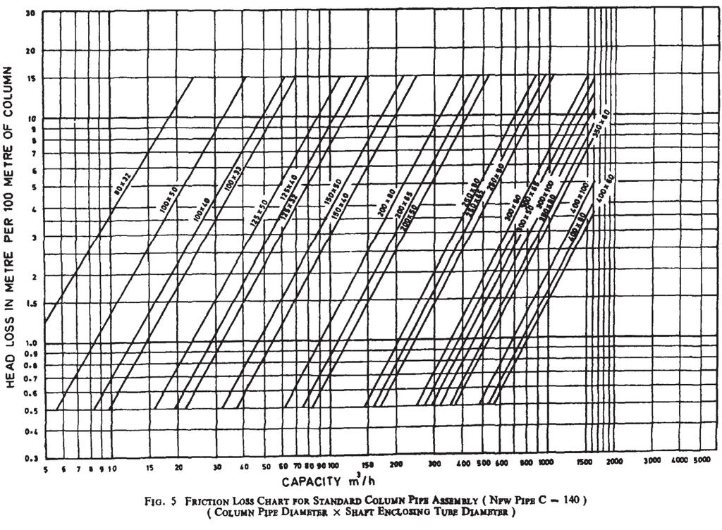
15 The shaft sections shall be provided with a non-corrosive wearing surface, except in the case of stainless steel shafts, particularly at the location of each guide bearing Line Shaft Bearings These shall be designed to be lubricated by external water or the water being pumped and shall be placed in bearing holders held in position at the joint of the columns Gland protection Water slinger of adequate diameter shall be provided to prevent water from creeping to the motor Discharge Head Assembly The discharge head shall have an arrow indicating the direction of rotation of pump The discharge head may have a stuffing box with a renewable bushing. Before starting of the pumps, the pre-lubrication connection to be provided to wet the line shaft bearings of rubber type for static water level above 15 meters. For dry start of the pump, suitable bearings shall be used Where manual control is used and a source of fresh water under pressure is not available, a pre-lubricating tank, with necessary valves and fittings to connect it to the pump, shall be provided. The size of the tank shall be adequate to permit through wetting of all the line shaft bearings before power is applied, with an adequate reserve for repeating the process in the event of the pump s failure to start in the first attempt. 10 ESSENTIALDESIGN FEATURES 10.1 The pumps shall satisfy the following basic design features: a) It shall have a rising head characteristics; b) The impeller adjustment shall be such that the impellers run free in any installed condition in spite of the extension of line shaft caused by hydraulic down-thrust, the weight of shafting and impellers; and c) It shall be designed for non-overloading of the prime mover. d) Noise and Vibrations shall be minimum as per acceptance criteria. 11 ENGINEERING DATA 11.1 Column Friction Loss The column friction chart (Fig. 5) shall be used as a design guide to determine the loss in head due to column friction. Head losses are considered where the flow is between the inside diameter of the column pipe and the outside diameter of the shaft enclosing tube. For open line shaft construction, the losses shown in Fig. 5 shall be used by assuming the losses equal to those indicated on the chart for shaft enclosing tube of a size that shall normally close the open line shaft in question. 13
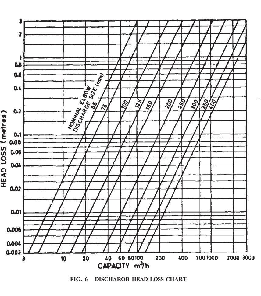
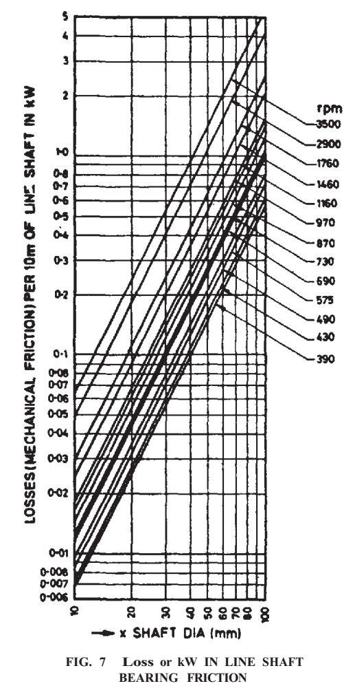
16 11.2 Discharge Head Loss The discharge at loss head chart (Fig. 6) shall be used for guidance to determine the hydraulic loss in the discharge head. Losses in the discharge heads vary with the size of the head, the design of the head and the size of the tubing or shaft column and discharge pipe used Mechanical Friction The mechanical friction chart (Fig. 7) shall be used to determine the added horse power due to mechanical friction in rotating the line shaft Thrust Bearing Loss Thrust bearing loss shall be declared by the manufacturer Sump Dimension and Submergence A chart showing various sump dimensions and minimum submergence for vertical turbine pump operating as single pump/multiple pump installation in a sump is illustrated in Fig. 8 (read with Fig. 4). These are recommended values, may be modified or changed, based on sump model test. 12 INFORMATION TO BE FURNISHED BY THE PURCHASER 12.1 When enquiring or ordering pumps to this standard, the user shall furnish the following information to the supplier: a) Name of the purchaser; b) Address; c) Installation site; d) Number of pumps required; e) Spare parts required; f) Type of drive: electric motor / engine; and g) Pump operating conditions: i) Capacity in l/s or m3/h; ii) Pump speed rev/min; iii) Head below ground level at rated capacity...m; iv) Head above ground level at rated capacity...m; v) Operating range minimum head and maximum head...m; vi) Special materials required to resist corrosion and/or erosion; and vii) Details of delivery connections sketch of pipe line layout giving information such as delivery pipe diameter and length, method of connection, distance between point of discharge and ground level, etc., may be given. h) Description of well (Fig. 9): i) Is the pump to be installed in open well tube well tube well ii) Minimum inside diameter of well or pipe ( A ) mm to a depth of... m; iii) Total depth of open well... m; iv) Total depth of top housing pipe for tube well ( B )... m; 14
17 v) Well slantness... mm out at... m; vi) Static water level below ground surface ( C )... m; vii) Pumping draw down ( D )... m at 1/s or m3/h; viii) Well developed to... l/s at... m of draw down; ix) In case of sump, details of sump and intake shall be furnished indicating pump position in it; and x) Maximum and minimum operating liquid levels in the sump... m. NOTE Sump layout and intake arrangement drawing shall be furnished by the purchaser. Site conditions: i) Height above mean sea level in metres; ii) Maximum and minimum temperature during the year ( C); iii) Humidity (percent); iv) Nature of atmosphere; and v) Details of quality of water (see 5.1). j) Prime-mover details: i) Direct electric motor drive, or ii) Pulley head drive, or iii) Gear head drive, or iv) Any other method. v) State which is required. a) In case of electric motor drive, give: i) Type of current(ac/dc, single-phase/three-phase); ii) Frequency (Hz); iii) Voltage; and iv) Preferred speed in rev/min. b) In case of pulley head and gear head drives through engine or electric motor, give the following details: i) Speed in rev/min; ii) Diameter of shaft (mm); iii) Length of shaft extension (mm); iv) Size of keyway (mm); v) Power (kw); vi) Diameter of engine/motor pulley (mm); vii) Electric motor data as in (K) (A); and viii) Direction of rotation of engine as observed from the driving end. A dimensioned sketch may be furnished, if required. k) Accessories: i) Size of companion delivery flange, if required... mm; ii) Whether suction strainer required or not; and iii) Type of starter and protection required. m) Any other information or requirement. 15 the
18 13 INFORMATION TO BE FURNISHED BY THE SUPPLIER 13.1 When supplying pumps according to this standard the supplier shall furnish the following information to the purchaser: a) Code designation of pump; b) Type of pump giving: 1) Method of lubrication: oil/water lubricated; 2) Suitability in tube well of size... mm diameter. 3) Number of stages; 4) Maximum outside diameter of bowl... mm; 5) Design discharge l/s or m3/h; 6) Effective head... m; 7) Pump speed... rpm; 8) Bowl assembly head... m; 9) Bowl assembly input at duty point... kw/pump input at duty Point; 10) Maximum bowl input... kw; 11) Bowl assembly efficiency at duty point... %; and 12) Maximum pump input... kw; c) Details of column assembly: 1) Length of column pipe.. m; 2) Method of connection of column pipe threaded/flanged; 3) Size of shaft enclosing tube... mm; 4) Size of line shaft... mm; 5) Size of discharge outlet... mm; 6) type of discharge head, surface, below base, if below base distance from datum reference to Centre line of discharge tee... mm; d) Details of drive: 1) In case of direct drive through electric motor, give; i) Rating... kw; ii) Type : squirrel cage/slip ring/drip proof/vertical/hollow-spindle/solid shaft; iii) Details of power supply; and iv) Revolutions per minute. 2) In case of gear head drive, give: i) Model; ii) Speed rating; iii) Operating speed; iv) Details of pulley or coupling; v) Direction of rotation; and vi) Rating of driver... kw. 3) In case of pulley head drive, give: i) Model; ii) Type of belting to be used: 16
19 V/Flat Width of flat belts... mm No. of V-belts... Section of V-belts iii) Vertical pulley diameter range... mm; iv) Driver pulley diameter range... v) Power rating of the driver... mm; and kw. e) Accessories: 1) Suction pipe: i) Diameter and length of suction pipe; ii) Method of connection : screwed/ bolted; and iii) Strainer : size and type 2) Depth gauge, direct or indirect reading type with size and length of airline pipe; 3) Lubricator: automatic/manual/other type; 4) Pre-lubricating tank/foot-valve with strainer in case of water-lubricated pump, wherever possible; 5) A pair of column pipe clamps; 6) A pair of shaft clamps; 7) Sight gauge in case of oil-lubricated pump, wherever possible; 8) Pressure gauge; 9) Gauge cock; 10) Reflux valve; 11) Sluice valve; 12) Float switches; and 13) Spanners. f) Additional information to be furnished with the supply: 1) Performance curve of head v discharge; 2) Performance curve of the pump showing total bowl assembly input power and bowl assembly efficiency over the specified head range; 3) Certified drawings giving leading dimensions; 4) Instructions for installation and maintenance; and 5) Weight of the pump, the right angle gear head, pulley head and the electric motor, if required. 14 PUMP TEST 14.1 Performance Test The expected field performance of the pump may be obtained by testing the bowl assembly in the laboratory and then calculating the required performance (see Fig. 10). A typical laboratory test set up as shown in Fig Laboratory Tests 17
20 As far as possible, full load and full speed tests shall be conducted. However, laboratory test at reduced speed and reduced stages shall be according to IS Sampling The sampling plan as given in IS 10572shall be followed Field Tests A field test gives an indication of the overall performance of a pump when it is operating under actual field conditions. Field tests are sometimes used as acceptance test. The accuracy with which field test be made depends on the instruments used in the test, the proper installation of the instruments and the skill of the test personnel. It shall be recognized that environmental conditions in a well or the design of a pump shall significantly affect field performance and also affect the apparent results of field test. Under most conditions, it is recommended that acceptance of the pump shall be based on tests made in laboratory. Field test shall not be carried out until the pump has worked for at least 24 hours to allow running in time for the bearings. If test is to be carried out at different heads, this shall be done by throttling the delivery valves, in this case delivery valve be placed after the minimum upstream and downstream length as required by flow measuring device. The control valve shall be at least 4 times the diameter away from the discharge head elbow. A typical diagrammatic arrangement for field test is illustrated in Fig. 12. For details, refer IS Speed The rotating speed of pump shall be measured by revolution counter or by an accurately calibrated tachometer or by stroboscope counting slip method Discharge The discharge of the pump shall be measured by means of a standard venturi tube, nozzle, orifice plate, V- notch/rectangular weir, pitot tube, traverse or any other recognized method. The method adopted for discharge measurement shall be suitable for the size of pump, its duty, and situation. The pump manufacturer shall, if required give evidence of the proper calibration of the apparatus used. Flow measuring devise like magnetic flow meter, ultrasonic flow meter may be used. The surface conditions, size and length of the pipe preceding and succeeding the fluid measuring device are as important as the calibration of the device itself and shall be taken care Net Pump Effective Head For determining the net pump effective head, following measurement shall be taken and the readings shall be converted to datum reference: 18
21 a) Static water depth with pump in working condition; b) Delivery head; and c) Velocity head Delivery head This shall be measured by means of a calibrated bourdon tube gauge (reading converted to meter of liquid) located at a distance of 2D from the discharge elbow of the test pump (D is diameter of delivery pipe) plus the distance from the datum to the centreline of gauge. It is recommended that mercury manometers be used in preference to bourdon type gauges when the head to be measured is 7.5 m or less. For precautions and connections for the gauge refer of IS 5120.Head measuring device like pressure transducer may be used Velocity head Velocity head shall be obtained from the actual measurement of the inside diameter of the discharge pipe at the point where the pressure tap is located (see ) Pump Output This shall be calculated as in Pump Input Pump Input shall be measured by calibrated power meter or Two wattmeter method" Overall Efficiency When the specifications calls for an overall efficiency guarantee, the actual job motor shall be used without calibration and efficiency calculated directly (see ). 15 RECORDING AND COMPUTATION OF TEST RESULTS 15.1 All instruments test readings as well as corrected readings shall be recorded on the test sheet. Complete data concerning the pump driver and instrument identification shall also be recorded All the test results shall be converted into performance at the specified speed from the actual readings, by the following similarity relations: = = ( = Where ) ( ) Q is capacity, H is head, P is power, 19
22 n is specified operating speed, and t indicates test values Bowl Assembly Input Power ( P ), (see ) Bowl Head, (see ) Bowl Efficiency, (see ) Effective Head ( h ) h = H hc hd hs in which H is the bowl assembly head, hc is the column loss based on complete pump setting, hd discharge head loss in metre, and hs is suction head Pump Efficiency, (see ) 15.8 Overall Efficiency Pump efficiency multiplied by the motor efficiency shall give the overall efficiency of the unit, if there is no intermediate driver The bowl assembly head, bowl efficiency and bowl assembly input power shall be plotted as ordinates on graph against the capacity as abscissa to show the anticipated field performance of the complete pump. 16 GUARANTEES For guarantee of the pumps with Class C ratings, 4.1 and 9.4 of IS 9137, and with class B ratings, 4 and 9.4 of IS 10981shall be referred. Unless otherwise specified, the guarantee shall be as per IS 9137as stated above. Comment by SLA 1) Better to reproduce clauses from IS9137, so that one need not refer to that standard just for this clause. 2) Alternatively, since IS has been made quite comprehensive and provides logic applicable for all water-handling pumps, it may be checked whether reference can be made to IS instead of IS Members may please note for comments Guarantee of Workmanship and Material The pumps shall be guaranteed by the manufacturer against defects in material and workmanship, under normal use and service, for a period of at least 15 months from the date of despatch or 12 months from the date of commissioning whichever is less. 20
23 16.2 Guarantee of Performance The pump shall be tested for the operating head range. However, the range shall be between +10 percent and 25 percent of the rated head. Below 30 m, the limit shall be from 25 percent to +2.5 percent or ± 3 m whichever is less. The tolerance on discharge shall be ± 2.5 percent and for the other duty points, tolerance shall be according to Annex A of IS The efficiency of vertical turbine pump shall be guaranteed at the specified point of rating only and shall not be guaranteed to cover the performance of the pump under conditions varying there from nor for a sustained performance of any period of time. However, pump discharge may be guaranteed for the range of head between 25 percent and +10percent of the specified head when the latter is 30 metres or above. Below 30 metres the limits shall be ± 25 percent or ± 3 metres whichever is less. 17 STANDARD MARKING 17.1 The pumpsets may also be marked with BIS Standard Mark The use of the Standard Mark is governed by the provisions of Bureau of Indian Standards Act, 1986 and the Rules and Regulations made thereunder. The details of condition under which the license for the use of Standard Mark may be granted to manufacturers or producers may be obtained from the Bureau of Indian Standards. 21
24 ANNEX A (Clause 2) LIST OF REFERRED INDIAN STANDARDS IS No. 210 : : : : : (Part 1) : (Part 5) : 1985 IS/ISO : : : : : : : : : : : : : 1988 Title Grey iron castings ( third revision ) Structural steel (standard equality) ( fifth revision ) Leaded tin bronze ingots and castings( second revision ) Three-phase induction motors ( fourth revision ) Carbon steel casting for general engineering purposes ( fourth revision ) Mild steel tubes ( fourth revision ) Schedules for wrought steels : Part 5 Stainless and heat resisting steels (second revision) Mechanical vibration - Balance quality requirements for rotors in a constant (Rigid) state : Part 1 Specifications and verification of balance tolerances Line pipe( second revision ) Weldable structural steel ( third revision ) Assessment of surface roughness Corrosion resistant high alloy steel and nickel based castings for general applications ( second revision ) Steel tubes used for water wells ( first revision ) Technical requirements for roto-dynamic special purpose pumps (first revision) Hot-rolled bars for production of bright bars Code for acceptance test for centrifugal, mixed flow and axial pumps Class C Methods of sampling for pumps Code of acceptance test for centrifugal, mixed flow and axial pumps Class B Class of acceptance test for centrifugal mixed flow and axial pumps - Class B Tests for Agricultural and Water Supply Pumps - Code of Acceptance Specification for Pumps for Fire Fighting System 22
25 ANNEX B (Clause 7.1 ) NOMENCLATURE OF PARTS COMMONLY USED IN VERTICAL TURBINE PUMPS DRIVEN BY SHAFT MOTOR Part No. (1) Name of the Part 1 Air line* A thin tube installed alongside the pump and submerged in liquid for the purpose of finding the liquid level. 2 Automatic lubricator It is a solenoid operated lubricator providing oil to the line shaft bearing automatically when motor is started. 3 Bearing holder Cast iron/bronze IS 318 : 1981 Used to support open line shaft bearing, generally located at the end of each section of column pipe. 4 Bearing retainer Cast iron IS 210 : 1978 Retains open line shaft bearing in the bearing holder. 5 Bottom column pipe Steel IS 1239 (Part 1) : 2004 or IS First section of column immediately above discharge case : Bowl Cast iron It guides flow received from one impeller to the next impeller above. It houses impeller and bowl bearing. 7 Bowl bearing Bronze/rubber IS 318 : 1981 Bearing for the impeller shaft in each bowl. 8 Column flange Cast iron/ Steel Grade A of IS 2062 : 2011 These are mounted on two ends of each section column pipe if flange column pipe is used. May take the firm lugs. (2) Typical Material (3) Material Specification Brief Description and Function of Parts (4) (5) 23
26 9 Column pipe Steel Grade A of IS 2062 : 2011 The raising main through which liquid goes up. 10 Column pipe adopter Cast iron/ Steel Transition piece between the bowl assembly and the column pipe used, if required. 11 Column pipe coupling Steel/ Cast iron IS 2062 : 2011 IS 2062 : Column pipe spacer Cast iron Aligning ring between two column ends. Use of this is optional. 13 Depth gauge Measuring device 14 Discharge case Cast iron It is situated between top bowl and bottom column pipe and guides flow from one to the other, column pipe 15 Discharge case bearing Bronze/rubber IS 318 : 1981 Bearing in discharge case which also serves to connect the guides flow from one to the other, column pipe. 16 Stuffing box gland Cast iron/bronze This tightens packing at discharge head and guide head shaft. 17 Flanged column Cast iron/steel IS 2062 : 2011 The column pipe section with bolting arrangement at the two ends. 18 Foot-valve-cum-strainer (not shown in Fig. 2) Cast iron/steel To hold liquid in column so as to lubricate the bearing of pumps. 19 Guide spinners Cast iron/bronze/steel, IS 2062 : To stabilise shaft enclosing tube or IS 318 : Head shaft Carbon steel IS 1570 (Part 5) : 1985 Top shaft passing through the driver hollow shaft and connecting the line shaft. 21 Head shaft coupling Steel IS 1030 : 1998 It connects head shaft with line shaft. For connecting column pipe section having threaded ends. Instruments for indicating liquid level. It may be direct or indirect reading type 24
27 22 Impeller Cast iron/bronze/steel 23 Impeller adjusting nut Steel 24 Impeller collect Stainless steel/steel 25 Impeller seal ring Bronze/cast iron 26 Impeller shaft Steel/carbon steel 27 Impeller shaft coupling 28 IS 318 : 1981 IS 3444 : 1999 IS 1030 : 1998 The rotating elements producing head. It receives liquid and impels to bowl passage. It may be enclosed or semi-enclosed. Provides on head shaft for adjusting impellers vertically by raising or lowering shaft. Spilt taper sleeve for locking impeller on impeller shaft. IS 1570(Part 5) : 1985 IS 7283 : 1992 IS 318 : 1981 Wearing ring providing seal to enclosed impeller. It may be either on the impeller or in the bowl or on both. Impellers are mounted on it. It is coupled to the line shaft. Steel IS 1570 (Part 5) : 1985 IS 7283 : 1974 IS 1030 : 1998 IS 1030 : 1998 Line shaft Carbon steel IS 7283 : 1974 Sections of shaft between the impeller shaft and head shaft. 29 Line shaft bearing Rubber/bronze IS 318 : 1981 Bearing for the line shaft sections. Also acts as a coupler for shaft enclosing tube in oil lubricated pumps. 30 Line shaft coupling Steel IS 1030 : 1998 These connects line shaft sections. 31 Water deflector Steel/rubber IS 2062 : 2011 Device to throw off leakage liquid from discharge head gland, thus preventing entry into driver unit. 32 Manual lubricator 33 Non-reverse ratchet Cast iron Device to prevent reverse rotation of the pump. 34 Open line shaft sleeve Stainless steel/steel IS 1570 (Part 5) : 1985 Sleeve operating as journal for the bearing of water lubricated pumps. It connects bottom line shaft to impeller shaft, may be tapped with the two different thread diameters. Lubricator with an arrangement for manually adjusting the oil flow to the line shaft bearing. 25
28 35 36 Pre-lubricating tank (not shown in Fig. 2) Safety clutch When supplied, it provides lubricants to the bearing of the pumps. 37 Sand collar (suction case) Plastic/bronze IS 318 : 1981 It prevents entry of sand into the suction case bearing. 38 Shaft enclosing tube Steel IS 2062 : 2011 It encloses line shafts. 39 Stuffing box Cast iron/steel IS 1030 : Stuffing box packings Asbestos Used for sealing of liquid at discharge head along head shaft. Acts also as a guide to the head shaft. Used in stuffing box for sealing off liquid from discharge head. 41 Suction case Cast iron It guides the flow into the eye of the lowest impeller and carries the suction case bearing of the impeller shaft. 42 Suction case bearing Bronze/rubber IS 318 : 1981 The guide bearing of the impeller shaft located in suction case. 43 Suction case plug Cast iron 44 Suction pipe Steel IS 1239(Part 1) : 2004 It prevents entry of sand into the suction case bearing and provides a port to grease this bearing. It helps to streamline flow to suction case and provides a safety measure in case of draw down level going below the lowest impeller. 45 Suction strainer 46 Surface discharge head 47 Threaded column 48 Top bowl bearing Top half is mounted on the head shaft and bottom half on the driving shaft for the purpose of disengagement if unscrewing shafts takes place during reverse rotation. It prevents entry of large foreign matter. Cast iron/steel It supports column and driver and discharge liquid from pump column. IS 2062 : 2011 IS 1239(Part 1) : 2004or IS Column pipe with threaded ends : 1982 Bronze/rubber IS 318 : 1981 A long bearing usually inserted in the top bowl. 26
29 49 Top column pipe IS 1239 (Part 1) : 2004or IS A connecting piece between top column pipe and discharge head : Top column gasket 51 Top column pipe Steel IS 2062 : 2011 For suction of column pipe below discharge head. 52 Tube tension nipple Steel/cast iron IS 226 : 1975 A short piece of shaft tube generally provided at the top end of shaft tube assembly to provide additional bearing close to the head shaft or to make up the required length of pump assembly. It is connected to the tube tension plate. 53 Tube tension plate Steel/cast iron Used for tensioning shaft tubes for alignment. 54 Tubing adaptor Steel/cast iron IS 2062 : 2011 IS 2062 : Underground head discharge Steel/cast iron IS 2062 : 2011 Supports driver and column assembly when discharge is below surface. 56 Underground tee discharge Steel IS 1239 (Part 1) : 2004 or IS This takes up discharge below the base plate, also forms part of column : Impeller adjusting nut Steel IS 7283 : 1992 Locks adjusting nut in place so that adjustment cannot change lock screw or washer while pump is in operation. 58 Base plate Cast iron/steel IS 2062 : 2011 Fabricated or casting that supports discharge head and part of foundation after initial installation. flange Rubber It prevents leakage of liquid from top column flange. A short piece connecting discharge case to the shaft tube. 27 may become permanent
30 ANNEX C (Clause7.1) NAME OF PARTS COMMONLY USED IN VERTICAL TURBINE PUMPS WITH SOLID SHAFT MOTOR Part No. (1) Name of the Part Material Specification (4) Brief Description and Function of Parts (2) Typical Material (3) 1 Suction bell Cast iron It guides the flow into the eye of the lowest impeller. 2 Impeller Cast iron/bronze IS 318 : 1981 The rotating element producing head. It received liquid and impels it to bowl passage. It may be enclosed or semi-enclosed. 3 Impeller spilt/ring Steel impeller locknut IS 7283 : 1992 To lock impeller on shaft. 4 Impeller seal ring Cast iron, bronze Wearing ring providing water seal to enclosed impellers. This may be fitted in bowl or on impellers. 5 Bowl Cast iron It guides flow received from one impeller to the next impeller above it and houses impeller and bowl bearing. 6 Impeller shaft Stainless steel IS 1570 (Part 5) It holds the rotating impellers and coupled : 1985 to the line shaft. (5) 28
31 7 Shaft sleeve 8 Bowl-bearing/ Top Rubber, bronze bowl bearing IS 318 : 1981 Bearing used for impeller shaft in each bowl. 9 Impeller key Steel IS 7283 : 1992 For mounting impeller on impeller shaft. 10 Taper rising pipe Cast iron/ steel IS 2062 : 2011 It delivers water from top bowl to column pipe. 11 Impeller shaft Steel coupling Stuffing box Cast housing iron/steel IS 1030 : 1998 It connects line shafts to impeller shaft. IS 1030 : 1998 Used for sealing off liquid at discharge head along head shaft. Acts also as a guide to head shaft provide with sleeve. 12 Stainless steel 13 Stuffing packing 14 Stuffing box gland 15 Head shaft IS 1570 (Part 5) Sleeve operating as journal for the boring : 1985 lubricated pumps. box Asbestos Cast iron/ bronze Used in the stuffing box for sealing off water leaking from discharge head. IS 318 : 1981 This tightens packing at discharge head and guides head shaft. shaft/line Stainless steel/ Steel IS 1570 (Part 5) A shaft connecting the line shaft to motor : 1985 shaft. IS 2073 : 1970 Bearing housing Cast iron It houses thrust bearing which takes care of the thrust load due to hydraulic axial thrust and weight of rotating parts. Pump half coupling Steel/cast iron IS 1030 : 1998 It is coupled to pump half coupling and drives head shaft. 29
32 18 Impeller adjusting Steel nut Steel IS 7283 : 1992 Provided on head shaft for adjusting impeller vertically. 19 Motor coupling IS 1030 : 1998 It is coupled to pump half coupling and drives head shaft. 20 Key coupling 21 Motor skirt 22 Surface discharge head/underground discharge tee Cast iron/steel 23 Foundation base Steel half Steel/cast iron Stainless steel/ Steel IS 1570 (Part 5) Used to fit pump coupling on the shaft. : 1985 Cast iron/steel A part functioning as a base for the motor. IS 206 : 2010 It supports driver and column assembly. In IS 1239 (Part 1) case of discharge tee it takes of discharge : 2004 below the base plates, also forms parts of IS 1978 : 1982 column. IS 2062 : 2011 It is grouted in the foundation which forms a rigid support. It supports column assembly and discharge head 30
33 31
34 32
35 33
36 34
37 35
38 36
39 37
40 38
भ रत य म नक य क इ ज नय र ग वभ ग फ़ न पर अन प कर : ; फ + : ; ईम ल
 भ रत य म नक य क इ ज नय र ग वभ ग फ़ न पर अन प कर :2323 2509; फ + :91 11 2323 2509; ईम ल :med@bis.org.in र य पक प रच लन म मस द ल ख षण स पन स दभ द न क एम.ई.ड.20/ट 01 15 10 2018 प प क वषय स म त, एम.ई.ड. 20
भ रत य म नक य र य र क इ ज ननयरर ग व भ ग य पक पररच लन म मस द रल ख र षण स ञ पन
 भ रत य म नक य र य र क इ ज ननयरर ग व भ ग फ न पर अन प कर :23232509; फ स + :91 11 23232509; ईम ल :med@bis.org.in य पक पररच लन म मस द रल ख र षण स ञ पन स दभभ दद न क प प क व षय सम त,ए.ई.ड. 20 र वषत : 1 य र क
For BIS Use Only Doc: CED 50(7436) BUREAU OF INDIAN STANDARDS
 BUREAU OF INDIAN STANDARDS") For BIS Use Only Doc: CED 50(7436) BUREAU OF INDIAN STANDARDS DRAFT FOR COMMENTS ONLY (Not to be reproduced without the permission of BIS or used as an Indian Standard) Draft Indian Standard SPECIFICATION
For BIS Use Only Doc: CED 50(7436) BUREAU OF INDIAN STANDARDS DRAFT FOR COMMENTS ONLY (Not to be reproduced without the permission of BIS or used as an Indian Standard) Draft Indian Standard SPECIFICATION
प र ख स ख य ववषय TED 27 (13009) W - II ववद य त पक व ट र व ह प पक व तथ 30 मम ट प अ पतम पक व म पक (AIS 041:2015 प अमभन अमभग रहण)
 W - II ववद य त पक व ट र व ह प पक व तथ 30 मम ट प अ पतम पक व म पक (AIS 041:2015 प अमभन अमभग रहण)") Please Contact at Telefax ट ल फ क स: 011 2323 6311 E-mail: ted@bis.org. in व य पकप पकच ल म मस द प र ख प र षण स ल Ref Date ट ईड 27/ ट - 1 22 01 2019 व द य त ए ह इब र ड हन व षय सम तत, ट ईड 27 प) पकच वह इ
Please Contact at Telefax ट ल फ क स: 011 2323 6311 E-mail: ted@bis.org. in व य पकप पकच ल म मस द प र ख प र षण स ल Ref Date ट ईड 27/ ट - 1 22 01 2019 व द य त ए ह इब र ड हन व षय सम तत, ट ईड 27 प) पकच वह इ
Fire Protection. FP-XA End Suction
 Fire Protection FP-XA End Suction PRODUCT BULLETIN MODEL FP-XA END SUCTION CPS Model FP-XA End Suction pumps are used in a variety of fire fighting applications. These rugged and efficient centrifugal
सम मनत यहद प ई ह त ल हदए गए प र चपक म म ख प रपक च म खत पक त पक अध हस त क ष प भ ज
 Please Contact at Telefax ट ल फ क स: 011 2323 6311 E-mail: ted@bis.org. in व य पकप पकच ल म मस द प र ख प र षण स ल Ref Date ट ईड 02/ ट - 63 12 12 2018 स वचल म लपर व हक, स च ण प रण ल तथ अ तर ह इ जन ववषय सममतत,
ववषय ववद य त पक व ट र व ह ज म पक प वव (AIS 040:2015 प अमभन अमभग रहण )
") Please Contact at Telefax ट ल फ क स: 011 2323 6311 E-mail: ted@bis.org. in व य पकप पकच ल म मस द प र ख प र षण स ल Ref Date ट ईड 27/ ट - 10 22 01 2019 व द य त ए ह इब र ड हन व षय सम तत, ट ईड 27 प) पकच वह
Please Contact at Telefax ट ल फ क स: 011 2323 6311 E-mail: ted@bis.org. in व य पकप पकच ल म मस द प र ख प र षण स ल Ref Date ट ईड 27/ ट - 10 22 01 2019 व द य त ए ह इब र ड हन व षय सम तत, ट ईड 27 प) पकच वह
ईट ड 11/ ट
 वय पक पररच लन म मस द प रल ख प र षण स ज ञ पन स दभ ददन क ईट ड 11/ ट -64 24-01-2019 तकन क सममतत ईट 11 प र षत : 1. ईट ड 11 क सभ सदसय 2. ववद य त तक क ववभ र पररषद क सभ सदसय तथ 3. र च रख व ल अ य सभ न क य मह दय,
BUREAU OF INDIAN STANDARDS MECHANICAL ENGINEERING DEPARTMENT Please correspond at Phone: , Fax: ,
 BUREAU OF INDIAN STANDARDS MECHANICAL ENGINEERING DEPARTMENT Please correspond at Phone: 2323-2509, Fax: + 91 11 23232509, Email: med@bis.org.in DOCUMENT DESPATCH ADVICE DRAFT IN WIDE CIRCULATION Ref.
DESIGN FEATURES SPECIAL DESIGN FEATURES. Space Saving. Self Priming. Easy to install. Design Flexibility
 DESIGN FEATURES Space Saving Vertical arrangement saves valuable floor space. Self Prig Designed to operate with submerged impeller. Instantly serviceable. Low operation cost. Easy to install Self- contained
532: 2006 Bicycle tube valves and valve tubing Specification (third revision) 2414: 2005 Cycle and rickshaw pneumatic tyres (fourth revision)
 2414: 2005 Cycle and rickshaw pneumatic tyres (fourth revision)") For BIS use only Draft Indian Standard CYCLE RUBBER TUBES (MOULDED/JOINTED) SPECIFICATION (fourth revision of IS 2415) Not to be reproduced without the permission Last date for receipt of comments is of
For BIS use only Draft Indian Standard CYCLE RUBBER TUBES (MOULDED/JOINTED) SPECIFICATION (fourth revision of IS 2415) Not to be reproduced without the permission Last date for receipt of comments is of
MANAK BHAVAN, 9 BAHADUR SHAH ZAFAR MARG, NEW DELHI
 MANAK BHAVAN, 9 BAHADUR SHAH ZAFAR MARG, NEW DELHI 110002 य प च ल म द ह द भ : ट ईड 29/ट -10, ट -11 31 अग़ त 2015 त पम प त : व ष र श षण द त ववषय त,ट ईड 29 र त कत त : 1 पर व हन इ ज ननयर ग ववभ ग पर ष क च खन
Comments, if any, may please be made in the enclosed format and mailed to the undersigned at the above address.
 DRAFT IN WIDE CIRCULATION DOCUMENT DESPATCH ADVICE Ref. Date TED 6/T - 56 & 31 25-01-2012 AUTOMOTIVE BODY, CHASSIS, ACCESSORIES AND GARAGE EQUIPMENT SECTIONAL COMMITTEE, TED 6 ADDRESSED TO: 1. All Interested
7 The revised IS 8034:2002 and revised STI be implemented w.e.f. 1 Feb 2005.
 BUREAU OF INDIAN STANDARDS (CENTRAL MARKS DEPARTMENT-III) Our Ref: CMD-III/16:8034 25 Oct 2004 Subject: Implementation of revised IS 8034:2002 Submersible Pump Sets and revised STI (Doc:STI/8034/5 ) IS
VERTICAL TURBINE PUMP
 21A, Canning Street, Ground Floor, Kolkata 700001, (W.B) India Ph.: (033) 22308125, 39855288, Mob: 09339834915 Fax: (033) 2230 8125, E- mail: powerpointpumps@yahoo.co.in Website: www.powerpointpumps.com
Draft Indian Standard SAFES Part 1 Specification (Fifth Revision)
") Draft for Comments Only Draft Indian Standard SAFES Part 1 Specification (Fifth Revision) Not to be reproduced without the permission of Last date for receipt of BIS or used as a STANDARD comments is 31-01-2014
Draft for Comments Only Draft Indian Standard SAFES Part 1 Specification (Fifth Revision) Not to be reproduced without the permission of Last date for receipt of BIS or used as a STANDARD comments is 31-01-2014
क न द र य म ह व भ ग भ स द भ- स ए ड -III/16: IS न म बभ ग षय म ह- आई एस : 2003 क परभप लन ललए एस ट आई Doc: STI/12406/3, October 2017
 क न द र य म ह व भ ग - III भ स द भ- स ए ड -III/16: IS 12406 07 न म बभ 2017 ग षय म ह- आई एस 12406 : 2003 क परभप लन ललए एस ट आई Doc: STI/12406/3, October 2017 इस उपर क त व षय क स दर भ ह सक षम प र ध क र न
क न द र य म ह व भ ग भ स द भ- स ए ड -III/16: IS न म बभ ग षय म ह- आई एस : 1998 क परभप लन ललए एस ट आई Doc: STI/14587/3, October 2017
 क न द र य म ह व भ ग - III भ स द भ- स ए ड -III/16: IS 14587 07 न म बभ 2017 ग षय म ह- आई एस 14587 : 1998 क परभप लन ललए एस ट आई Doc: STI/14587/3, October 2017 इस उपर क त व षय क स दर भ ह सक षम प र ध क र न
1100 Series Multi-Stage Vertical Turbine Pumps
 1100 Series Multi-Stage Vertical Turbine Pumps Capacities to 40,000 GPM Heads to 1,500 Feet Temperatures to 200 F Water Lubricated Open Lineshaft Vertical Hollow Shaft Motor The vertical hollow shaft motor
DOC: STI/10322(Part 5/Sec 3)/2, September 2016
/2, September 2016") क न द र य म ह व भ ग 3 भ स द भ- क न द र य म ह व भ ग -3/16: आई एस IS 10322 5(Part /sec3) 04 अक त बभ 2016 ग षय म ह- आईएस IS 10322 5 (Part /sec3): 2012 क पवनभ क ष त एसट आई (एसट आई/10322 Part 5/Sec (3)/2, ससत
क न द र य म ह व भ ग 3 भ स द भ- क न द र य म ह व भ ग -3/16: आई एस IS 10322 5(Part /sec3) 04 अक त बभ 2016 ग षय म ह- आईएस IS 10322 5 (Part /sec3): 2012 क पवनभ क ष त एसट आई (एसट आई/10322 Part 5/Sec (3)/2, ससत
Application & Reference Data Typical Specifications. Section 914 Vertical Turbine Fire Pump
 Section 914 Page 101 Supersedes Section 913 Page 101 Dated November 1, 199p Application & Reference Data Typical Specifications Section 914 Section 914 Page 102 Supersedes Section 913 Page 102 Dated November
इल क र क स लल ग प ख व वषक टट ( प न क ण)
") BUREAU OF INDIAN STANDARDS Manak Bhavan, 9 Bahadur Shah Zafar Marg New Delhi 110002 Phones 2323 0131 2323 3375 Extn 4284 TeleFax +91 11 2323 1192 Website : www.bis.org.in email : eetd@bis.org.in व य पक
BUREAU OF INDIAN STANDARDS Manak Bhavan, 9 Bahadur Shah Zafar Marg New Delhi 110002 Phones 2323 0131 2323 3375 Extn 4284 TeleFax +91 11 2323 1192 Website : www.bis.org.in email : eetd@bis.org.in व य पक
Vertical Pumps for the Oil & Gas Industry
 Vertical Pumps for the Oil & Gas Industry Lenntech info@lenntech.com Tel. +31-152-610-900 www.lenntech.com Fax. +31-152-616-289 ITT API Expert ITT Commitment ITT is committed to the Oil and Gas market,
ISO 2953 INTERNATIONAL STANDARD. Mechanical vibration Balancing machines Description and evaluation
 INTERNATIONAL STANDARD ISO 2953 Third edition 1999-04-15 Mechanical vibration Balancing machines Description and evaluation Vibrations mécaniques Machines à équilibrer Description et évaluation A Reference
Not to be reproduced without permission Last date for receipt of BIS or used as STANDARD of comments 15 September 2011
 For Comments Only Doc: TED 19(821)W July 2011 Draft Indian Standard SHIPBUILDING TESTING OF MARINE DIESEL ENGINES- CODE OF PRACTICE (Second Revision of IS 3979) Not to be reproduced without permission
Draft Indian Standard FUSIBLE PLUG FOR DISSOLVED ACETYLENE GAS CYLINDER SPECIFICATION (first revision of IS 13497) (ICS )
 (ICS )") DRAFT STANDARD IN WIDE CIRCULATION DOCUMENT DESPATCH ADVICE Ref: MED 16 :3/T- 14 Date: 06-01-2015 Gas Cylinders, Sectional Committee, MED 16 TO: a) The interested members of Mechanical Engineering Division
DRAFT STANDARD IN WIDE CIRCULATION DOCUMENT DESPATCH ADVICE Ref: MED 16 :3/T- 14 Date: 06-01-2015 Gas Cylinders, Sectional Committee, MED 16 TO: a) The interested members of Mechanical Engineering Division
Contents. Identification
 Contents Identification Type key Product data Introduction Applications Features and benefits Performance range pole pole Construction Sectional drawing Construction features Test pressure Operating conditions
AUTOMOTIVE VEHICLES AIR BRAKE SYSTEMS PERFORMANCE REQUIREMENTS FOR DRAIN VALVES
 For BIS use only Draft Indian Standard AUTOMOTIVE VEHICLES AIR BRAKE SYSTEMS PERFORMANCE REQUIREMENTS FOR DRAIN VALVES Not to be reproduced or used as a Standard without permission from BIS Foreword (Formal
DOCUMENT DESPATCH ADVICE. Technical Committee: Petroleum and Related Products Sectional Committee, PCD 3
 DRAFT IN WIDE CIRCULATION DOCUMENT DESPATCH ADVICE REF: DATE Doc:PCD 3(2867)C 02 09 2015 Technical Committee: Petroleum and Related Products Sectional Committee, PCD 3 i) All interested members of PCDC
Government of India क ष एव ककस न कल य ण म त र लय, Ministry of Agriculture and Farmers Welfare (क ष, सहक ररत एव ककस न कल य ण षवभ ग)
") Page 1 of 12 Website: http://srfmtti.dacnet.nic.in/ E-mail: fmti-sr@nic.in Tele./FAX: 08551-286441 1. GENERAL: भ रत सरक र Government of India क ष एव ककस न कल य ण म त र लय, Ministry of Agriculture and Farmers
Page 1 of 12 Website: http://srfmtti.dacnet.nic.in/ E-mail: fmti-sr@nic.in Tele./FAX: 08551-286441 1. GENERAL: भ रत सरक र Government of India क ष एव ककस न कल य ण म त र लय, Ministry of Agriculture and Farmers
PROPOSED DRAFT INDIAN STANDARD. RECOMMENDED PUMPING SYSTEM FOR WATER SUPPLY PURPOSES PART 3 DOMESTIC PUMPSETS (Third Revision of IS 10804)
") Page 1 of 64 PROPOSED DRAFT INDIAN STANDARD RECOMMENDED PUMPING SYSTEM FOR WATER SUPPLY PURPOSES PART 3 DOMESTIC PUMPSETS (Third Revision of IS 10804) Sl. 1. 2. 3. 4. 5. 5.1. 5.2. 5.3. 5.4. 5.5. 5.6. 5.7.
Page 1 of 64 PROPOSED DRAFT INDIAN STANDARD RECOMMENDED PUMPING SYSTEM FOR WATER SUPPLY PURPOSES PART 3 DOMESTIC PUMPSETS (Third Revision of IS 10804) Sl. 1. 2. 3. 4. 5. 5.1. 5.2. 5.3. 5.4. 5.5. 5.6. 5.7.
F-Series Fire Fighting Pumps
 F-Series Fire Fighting Pumps VISION To be a leading local manufacturer and reliable partner providing engineered products and solutions to our customers. MISSION Supporting the socio-economic development
Bristol: A History & Future.
 Fire Pumps Bristol: A History & Future. In 1971, seven emirates joined forces to create the United Arab Emirates, with the goal of becoming a growing leader on an international scale. The UAE s focus has
ETD 39 (10038 ) ETD 39 (10039 ) ETD 39 (10040 )
 ETD 39 (10039 ) ETD 39 (10040 )") य प च ल म स द र ख र षण सञ पन स दभभ ईट ड 39/ ट -3, ट -6, दन क 29-02-2016 ट -15, ट -27, ट -28 तपम प सम तत ई ट 39... र षत : 1. ईट ड 39 क सभ सद य 2. व यत तकन क व भ ग पर षद क सभ सद य त 3. च खन अ य सभ नक य मह
य प च ल म स द र ख र षण सञ पन स दभभ ईट ड 39/ ट -3, ट -6, दन क 29-02-2016 ट -15, ट -27, ट -28 तपम प सम तत ई ट 39... र षत : 1. ईट ड 39 क सभ सद य 2. व यत तकन क व भ ग पर षद क सभ सद य त 3. च खन अ य सभ नक य मह
Automotive Vehicles Safety Belts, Restraint Systems and Safety Belt Reminder Installation Requirements
 ट ल फ क स : 23236311 Please Contact at Telefax 23236311 E-mail: ted@bis.org. in व य पक पर च लन म मस द DRAFT IN WIDE CIRCULATION रल ख र षण स चन /DOCUMENT DESPATCH ADVICE ट ईड 29/ट -16 TED 29/T-16 11-12-2015
Index - Section 40L. Large Sump or Drainage Pumps. Bulletin Bulletin 4500
 www.cranepumps.com Index - Section 40L ITEM S Typical Architect / Engineer Specifi cations - 4500 Series... 1 Guide Bearing and Shaft Selection 4500 Series... 2 Shaft and Guide Bearing Assemblies 4500
Doc:TED 11(794)W 1 September 2012 Draft Standard Automotive Vehicles - Windscreen Wiping System for 3 Wheeler Vehicles - Specification
W 1 September 2012 Draft Standard Automotive Vehicles - Windscreen Wiping System for 3 Wheeler Vehicles - Specification") For Comments only Doc:TED 11(794)W 1 September 2012 Draft Standard Automotive Vehicles - Windscreen Wiping System for 3 Wheeler Vehicles - Specification Not to be reproduced without permission Last date
For Comments only Doc:TED 11(794)W 1 September 2012 Draft Standard Automotive Vehicles - Windscreen Wiping System for 3 Wheeler Vehicles - Specification Not to be reproduced without permission Last date
Draft Indian Standard SYN GAS/ AMMONIA TURBO COMPRESSOR LUBRICATING OILS SPECIFICATION
 Comments Only BUREAU OF INDIAN STANDARDS Draft Indian Standard Doc:PCD 3(2537)C September 2012 SYN GAS/ AMMONIA TURBO COMPRESSOR LUBRICATING OILS SPECIFICATION Not to be reproduced without the permission
NC State University Design and Construction Guidelines Division 23 Hydronic Pumps
 1.0 Purpose A. The following guidelines apply to the selection of pumps primarily for circulating water. It is the goal of NC State to purchase pumps that are selected to provide a long service life, minimal
Doc: TED 7(743)W November 2009 Draft Indian Standard AUTOMOTIVE VEHICLES TUBES FOR PNEUMATIC TYRES SPECIFICATION (First Revision of IS 13098)
W November 2009 Draft Indian Standard AUTOMOTIVE VEHICLES TUBES FOR PNEUMATIC TYRES SPECIFICATION (First Revision of IS 13098)") For BIS Use Only Doc: TED 7(743)W November 2009 Draft Indian Standard AUTOMOTIVE VEHICLES TUBES FOR PNEUMATIC TYRES SPECIFICATION (First Revision of IS 13098) 0 FOREWORD (Formal Clause. Will be added later
For BIS Use Only Doc: TED 7(743)W November 2009 Draft Indian Standard AUTOMOTIVE VEHICLES TUBES FOR PNEUMATIC TYRES SPECIFICATION (First Revision of IS 13098) 0 FOREWORD (Formal Clause. Will be added later
CALCULATION OF BOWL HEAD OR DISCHARGE HEAD
 February, 1996 Supersedes 5/95 issue CALCULATION OF BOWL HEAD OR Pressure Gauge hd (Discharge Head) hl (LIFT) hp (Internal Pump Loss) Setting Sump Depth Pump O.A.L. Pumping Water Level hb (Bowl Head) For
PROCESS PUMPS (INDIA) PVT LTD
 PVT LTD") VERTICAL CANTILEVER SHAFT SUMP PUMP (PPCS)_ METALLIC INSTALLATION, OPERATION AND MAINTENANCE MANUAL PROCESS PUMPS (INDIA) PVT LTD Plot No.86, III Phase, Peenya Industrial Area, Bangalore 560058 Phone:
VERTICAL CANTILEVER SHAFT SUMP PUMP (PPCS)_ METALLIC INSTALLATION, OPERATION AND MAINTENANCE MANUAL PROCESS PUMPS (INDIA) PVT LTD Plot No.86, III Phase, Peenya Industrial Area, Bangalore 560058 Phone:
XFLO XS SERIES. Single Stage Double Suction Split Casing Centrifugal Pump
 XFLO P U M P S XS SERIES Single Stage Double Suction Split Casing Centrifugal Pump General and Construction 1. Applications Waterworks, Irrigation, Drainage pumping stations, Power stations, Industrial
4.1 Type of the valve and materials of construction of body and trim shall be as specified in valve Data sheet.
 SHEET 1 OF 5 1.0 GENERAL & SCOPE 1.1 This specification covers the design, material, construction features, manufacture, inspection & testing, Painting and packing requirements of Spring Loaded Bypass
INSTALLATION, OPERATION AND MAINTENANCE INSTRUCTIONS
 INSTALLATION, OPERATION AND MAINTENANCE INSTRUCTIONS Contents Section 1. General Observations... 2 2. Operation... 4 3. Control During Operation... 5 4. Trouble Shooting... 6 5. Maintenance... 7 Please
INTER PLANT STANDARD STEEL INDUSTRY
 INTER PLANT STANDARD STEEL INDUSTRY IPSS SPECIFICATION FOR ac CRANE (Hoist and Winches) DUTY SQUIRREL CAGE INDUCTION MOTORS (Fourth Revision) BASED ON IS 325:1996 Formerly: IPSS:1-03-004-05 0. FOREWORD
BEV. Deep well vertical pumps. 3. Design. 1. Fields of Application. 4. Designation. 2. Operating Data
 Type series booklet CTI-2000/00 [09-2010] BEV Deep well vertical pumps 1. Fields of Application BEV are vertical multistage centrifugal pumps designed for deep well, ditches and tanks to pump clean liquids
DESIGN OF MACHINE MEMBERS - I
 R10 Set No: 1 III B.Tech. I Semester Regular and Supplementary Examinations, December - 2013 DESIGN OF MACHINE MEMBERS - I (Mechanical Engineering) Time: 3 Hours Max Marks: 75 Answer any FIVE Questions
ISO INTERNATIONAL STANDARD. Seal-less rotodynamic pumps Class II Specification
 INTERNATIONAL STANDARD ISO 15783 First edition 2002-02-01 Seal-less rotodynamic pumps Class II Specification Pompes rotodynamiques sans dispositif d'étanchéité d'arbre Classe II Spécifications Reference
733:1983 Specification for Wrought aluminium and aluminium alloy Bars, rods and sections (for general engineering purposes) (third revision)
 (third revision)") For comments only Doc:TED 17(721)W June 2009 Draft Indian Standard ALUMINIUM SHORE GANGWAYS SPECIFICATION (First Revision of IS 10558) Not to be reproduced without permission Last date for receipt of BIS
For comments only Doc:TED 17(721)W June 2009 Draft Indian Standard ALUMINIUM SHORE GANGWAYS SPECIFICATION (First Revision of IS 10558) Not to be reproduced without permission Last date for receipt of BIS
Model 133 Models 134 & 135 AURORA 130 SERIES SINGLE STAGE TURBINE TYPE PUMPS
 Model Models 4 & AURORA 0 SERIES SINGLE STAGE TURBINE TYPE PUMPS WWW.AURORAPUMP.COM AURORA 0 SERIES Single Stage Turbine Type Pumps Capacities to 0 G.P.M. Heads to 700 Ft. Temperatures to F A Pioneer in
SUGGESTED SPECIFICATIONS
 PART 1 - GENERAL 1.01 SCOPE A. Pumps to be supplied under this specification shall be of a severe duty, recessed cupped impeller design suitable for use in (SLUDGE, GRIT, ETC. APPLICATIONS) with a 20 year
INTER PLANT STANDARD STEEL INDUSTRY. Corresponding IS does not exist
 INTER PLANT STANDARD STEEL INDUSTRY IPSS SPECIFICATION FOR ac ROLLER TABLE MOTORS (Second Revision) Corresponding IS does not exist IPSS:1-03-007-14 Formerly : IPSS:1-03-007-03 0. FOREWORD 0.1 This Inter
RS Multi-Stage, Ring Section Pumps
 RS Multi-Stage, Ring Section Pumps Technical Specification Pages This page left intentionally blank. 1.0 Overview. The RS Series is Carver s multi-stage pump for fluids at moderate to high pressures. The
HORIZONTAL SPLIT CASING PUMP
 OPERATION & MAINTENANCE MANUAL HORIZONTAL SPLIT CASING A Mark of Quality CROSS SECTION DRAWING No. DESCRIPTION MATERIAL 01 1/4 BSP PLUG BRASS 02 LOWER HOUSING C. I. IS-210, FG260 03 IMPELLER C. I. / G.
900 Series Split Case Fire Pump Systems
 BULLETIN 900/REV. E 900 Series Split Case Fire Pump Systems MODEL 481 MODEL 483 FM Approved U L Listed motralec 4 rue Lavoisier. ZA Lavoisier. 95223 HERBLAY CEDEX Tel. : 01.39.97.65.10 / Fax. : 01.39.97.68.48
Government of India क ष एव ककस न कल य ण म त र लय, Ministry of Agriculture and Farmers Welfare (क ष, सहक ररत एव ककस न कल य ण षवभ ग)
") Page 1 of 11 Website: http://srfmtti.dacnet.nic.in/ E-mail: fmti-sr@nic.in Tele./FAX: 08551-286441 1. GENERAL भ रत सरक र Government of India क ष एव ककस न कल य ण म त र लय, Ministry of Agriculture and Farmers
Page 1 of 11 Website: http://srfmtti.dacnet.nic.in/ E-mail: fmti-sr@nic.in Tele./FAX: 08551-286441 1. GENERAL भ रत सरक र Government of India क ष एव ककस न कल य ण म त र लय, Ministry of Agriculture and Farmers
SECTION AXIAL HVAC FANS
 SECTION 233413 - AXIAL HVAC FANS 1. PART 1 GENERAL 1.1. RELATED DOCUMENTS A. Drawings and general provisions of the Contract, including General and Supplementary Conditions and Division 01 Specification
HORIZONTAL SPLIT CASING PUMP
 HORIZONTAL SPLIT CASING PUMP HORIZONTAL PUMP CONSTRUCTION MBH Horizontal Split Casing Pumps - a new concept for better performance and higher efficiencies. For greater interchangeability and ease of maintenance,
The gear boxes can be run at the same speeds as the actuator models. Do not exceed torque ratings.
 1. What is the lifting torque required? The lifting torque for a single actuator depends on the load, the worm gear ratio, type of screw (machine cut or ball screw) and the pitch of the lifting screw.
EBARA Submersible Propeller Pumps Contents Project: Model: Chk d: Date: Model
 Contents Model A0553 C1125 V0494 A0713 C1285 V0554 A0843 C1455 V0754 A03 C15 V0854 C1915 V0974 C2185 V1154 C2905 Section Page Specifications 3-3 Model Designation 3-6 Impeller Data 3-8 Material Specifications
Doc:TED 11(794)W Dec Draft Standard Automotive Vehicles - Windscreen Wiping System for 3 Wheeler Vehicles - Specification
W Dec Draft Standard Automotive Vehicles - Windscreen Wiping System for 3 Wheeler Vehicles - Specification") For Comments only Doc:TED 11(794)W Dec 2010 Draft Standard Automotive Vehicles - Windscreen Wiping System for 3 Wheeler Vehicles - Specification Not to be reproduced without permission Last date for receipt
For Comments only Doc:TED 11(794)W Dec 2010 Draft Standard Automotive Vehicles - Windscreen Wiping System for 3 Wheeler Vehicles - Specification Not to be reproduced without permission Last date for receipt
Draft Indian Standard PERFORMANCE REQUIREMENTS AND METHODS OF TEST FOR WHEELS FOR PASSENGER CARS/MINI GOODS CARRIERS (First Revision of IS 9436)
") Draft for comments only Draft Indian Standard PERFORMANCE REQUIREMENTS AND METHODS OF TEST FOR WHEELS FOR PASSENGER CARS/MINI GOODS CARRIERS (First Revision of IS 9436) Not to be reproduced or used as
Draft for comments only Draft Indian Standard PERFORMANCE REQUIREMENTS AND METHODS OF TEST FOR WHEELS FOR PASSENGER CARS/MINI GOODS CARRIERS (First Revision of IS 9436) Not to be reproduced or used as
Data sheet. Customer item no.: Communication dated: Number: ES Doc. no.: Item no.: 100 Quantity: 1 Date: 19/03/2015 Page: 1 / 6
 Data sheet Item no.: Page: 1 / 6 Operating data Operating data determined for maximum inlet pressure Pumped medium Water Clean water Not containing chemical and mechanical substances which affect the materials
SJP Vertical Propeller Pumps
 Sulzer Pumps SJP Vertical Propeller Pumps The Heart of Your Process Sulzer Pumps Sulzer Pumps is a world leader in reliable products and innovative pumping solutions. Our advanced research and development,
Grupa Powen-Wafapomp SA. Pumps for Power and Heat Supplying Industries catalogue
 0 Grupa Powen-Wafapomp SA Pumps for Power and Heat Supplying Industries 2017 catalogue Contents 2 Basic pumps Supply pumps Z YS 4 10 Condensate pumps K i WK 20 Cooling water pumps D P 26 32 Hot water pumps
Draft Indian Standard Specification for Rubber Gaskets (First Revision of IS : 1984) ICS , ,
 ICS , ,") For BIS Use Only Draft Indian Standard Specification for Rubber Gaskets (First Revision of IS 11149 : 1984) ICS 23.040.80, 83.060, 83.140.50 Not to be reproduced without the permission of Last date for
For BIS Use Only Draft Indian Standard Specification for Rubber Gaskets (First Revision of IS 11149 : 1984) ICS 23.040.80, 83.060, 83.140.50 Not to be reproduced without the permission of Last date for
Bulletin BX-512H. Bell & Gossett. Series HSC-S Pumps Technical Bulletin. Bell & Gossett. Part of the. Equipment Selection Programs
 Bulletin BX-1H Bell & Gossett Series HSC-S Pumps Technical Bulletin Part of the Bell & Gossett Equipment Selection Programs TABLE OF CONTENTS Useful Pump Formulas...............................................
TYPE PC Propeller Condensate Pumps
 SHIPPENSBURG PUMP CO. INC. P.O. BOX 279, SHIPPENSBURG, PA 17257 PH 717-532-7321 FAX 717-532-7704 WWW.SHIPCOPUMPS.COM BULLETIN 103 Revised 8/17 TYPE PC Propeller Condensate Pumps with Cast Iron Receivers
Elite. KSB Australia Pty Ltd. Centrifugal Pump
 Type Series Booklet Elite Centrifugal Pump Application The Ajax Elite centrifugal pump is suitable for handling water and similar liquids mainly used in the following applications. -Water Supply -Air conditioning
PRINCIPLES OF OPERATION
 "Magnetic Drive" refers to the coupling between the wet end of the pump and the motor. In "direct drive" pumps, the impeller of the pump is attached to the shaft of the motor, and this design depends on
Data sheet. Page: 1 / 5 ETN GG A 11GA201502B. Operating data. Design. Requested developed head m. Efficiency 74.
 Data sheet Page: 1 / 5 Operating data Requested flow rate 160.00 m³/h Actual flow rate 159.85 m³/h Operating data determined for maximum inlet pressure Actual developed head 20.96 m Requested developed
NORTHWESTERN UNIVERSITY PROJECT NAME JOB # ISSUED: 03/29/2017
 SECTION 23 2123 - PUMPS PART 1 - GENERAL 1.1 RELATED DOCUMENTS A. Drawings and general provisions of the Contract, including General and Supplementary Conditions and Division 01 Specification Sections,
LUBE OIL PUMPS. Critical Lubrication Service for: Bearings Seals Gearboxes. on... Gas & Steam Turbines Compressors Engines Starting Packages
 LUBE OIL PUMPS Critical Lubrication Service for: Bearings Seals Gearboxes on... Gas & Steam Turbines Compressors Engines Starting Packages LEADING SUPPLIER OF LUBE OIL PUMPS TO THE POWER GENERATION INDUSTRY
Waterfall Pumps Manufacturing
 Waterfall Pumps Manufacturing Our Vision for the future to become the world s premier provider of fire protection pumps. Our ongoing mission is to be the customers first choice, a trusted provider and
DSZ3. EBARA Submersible Propeller Pumps Contents Project: Model: Chk d: Date: Model
 Contents Model A0553 C1125 V0494 A0713 C1285 V0554 A0843 C1455 V0754 A1003 C1605 V0854 C1915 V0974 C2185 V1154 C2905 Section Page Specifications 3-203 Model Designation 3-206 Impeller Data 3-208 Material
म नक भवन, 9 बह द रश ह फर म ग, नई दद ल
 म नक भवन, 9 बह द रश ह फर म ग, नई दद ल 110002 Manak Bhavan, 9 Bahadur Shah Zafar Marg, New Delhi 110002 द रभ ष 23231282 Website: www.bis.org.in त र: म नकस थ Phones 23230131 email: txd@bis.org.in Grams:
ईट ड 16/ ट
 य पक प रच लन म मस द ल ख षण स पन तकन क स म त ईट ड : 16 ---------------------------------------------------------------------------------------------------------------------------------- षत : 1. ईट ड 16
Disclosure to Promote the Right To Information
 इ टरन ट म नक Disclosure to Promote the Right To Information Whereas the Parliament of India has set out to provide a practical regime of right to information for citizens to secure access to information
European Fire Pump Listing
 European Fire Pump Listing EN12259-12 Current Status of European Listings Germany - National Listings France - National Listings UK - National Listings Poland - National Listings Hungary - National Listings
S M A R T P U M P I N G HORIZONTAL MULTISTAGE CENTRIFUGAL PUMP
 HORIZONTAL MULTISTAGE CENTRIFUGAL PUMP Nuton horizontal multistage centrifugal pumps are engineered to perfection with utmost care and stringent quality control at all stages to ensure a trouble free service.
Data sheet. Omega B GB G F Version no.: 1. Operating data. Design. Driver, accessories. Clean water. Actual developed head 57.
 Data sheet Item no.: 3700 Page: 1 / 5 Operating data Pumped medium Water Actual flow rate 415.38 m ³/h Clean water Actual developed head 57.81 m Not containing chemical and Efficiency 82.3 % mechanical
PUMP TYPE SERIES SLM AVP ACCORDING TO API 685
 Production range pumps: Pumps with magnet drive E Chemical centrifugal pumps according to DIN EN E Centrifugal pumps according to ANSI B. E Centrifugal pumps for refinery and petrochemical applications
SUGGESTED SPECIFICATIONS Pump Frames NS3 thru OMC5
 SOLIDS-HANDLING WASTEWATER PUMPS Pump Frames NS3 thru OMC5 GENERAL Furnish and install Vertical Closed-Shaft Wet-Pit Pumping Units complete with all accessories and appurtenances as shown in the plans
M-18 Controllable-Pitch Propeller
 Guideline No.M-18(201510) M-18 Controllable-Pitch Propeller Issued date: 20 th October, 2015 China Classification Society Foreword This Guideline is a part of CCS Rules, which contains technical requirements,
Bulletin C Dean Pump Division. Heavy Duty, High Temperature Process Pumps. R4140 Telescoping Guard. R4140 C-Face Motor Support
 Bulletin C 1.4.43 Dean Pump Division Heavy Duty, High Temperature Process Pumps R4140 Telescoping Guard R4140 C-Face Motor Support Dean Pump Series R Centrifugal Process Pumps Capacities to 5000 GPM (1135
INTER PLANT STANDARD STEEL INDUSTRY. SPECIFICATION FOR GENERAL PURPOSE SQUIRREL CAGE INDUCTION MOTORS (Fifth Revision) BASED ON IS 325:1996
 BASED ON IS 325:1996") INTER PLANT STANDARD STEEL INDUSTRY IPSS SPECIFICATION FOR GENERAL PURPOSE SQUIRREL CAGE INDUCTION MOTORS (Fifth Revision) BASED ON IS 325:1996 IPSS: 1-03-001-14 Formerly: IPSS:1-03-001-05 0. FOREWORD
INTER PLANT STANDARD STEEL INDUSTRY IPSS SPECIFICATION FOR GENERAL PURPOSE SQUIRREL CAGE INDUCTION MOTORS (Fifth Revision) BASED ON IS 325:1996 IPSS: 1-03-001-14 Formerly: IPSS:1-03-001-05 0. FOREWORD
SECTION PUMPS GENERAL PUMPS PART RELATED DOCUMENTS
 SECTION 15160 - PUMPS PART 1 - GENERAL 1.01 RELATED DOCUMENTS A. Basic Requirements: Provisions of Section 15010, BASIC MECHANICAL REQUIREMENTS and Section 15030, ELECTRICAL REQUIREMENTS FOR MECHANICAL
ISO INTERNATIONAL STANDARD. Mechanical vibration Rotor balancing Part 21: Description and evaluation of balancing machines
 INTERNATIONAL STANDARD ISO 21940-21 First edition 2012-07-15 Mechanical vibration Rotor balancing Part 21: Description and evaluation of balancing machines Vibrations mécaniques Équilibrage des rotors
ट ईड 6/ TED 7/T
 ट ल फ क स :23236311Please Contact at Telefax 23236311 E-mail: ted@bis.org. in व य पकप पकच ल लम म स DRAFT IN WIDE CIRCULATION प रल ख प र षण स चन /DOCUMENT DESPATCH ADVICE ट ईड 6/ TED 7/T-61 06-07 -2016
G&L Pumps. TECHNICAL Brochure BAC8100. Series A-C 8100 SPLIT CASE PUMPS
 TECHNICAL Brochure BAC8 Series A-C 8 SPLIT CASE PUMPS TABLE OF CONTENTS Useful Pump Formulas 2 Performance Curves 3-5 Materials of Construction (Standard) 6 Materials of Construction (Optional) 7 Pump
Medium and high pressure pumps
 Screw pumps Medium and high pressure pumps Installation and Start-up Instruction This instruction is valid for all standard high pressure pumps: E4, D4 and D6 Contents Page Pump identification 2 Installation
 DEPARTMENT OF MECHANICAL ENGINEERING Subject code: ME6601 Subject Name: DESIGN OF TRANSMISSION SYSTEMS UNIT-I DESIGN OF TRANSMISSION SYSTEMS FOR FLEXIBLE ELEMENTS 1. What is the effect of centre distance
य पक प रच लन मस द प स ड 25(2700) तकन क स म त प स ड 25
 तकन क स म त प स ड 25") य पक प रच लन मस द स दभ दन क प स ड 25(200) 24-06-2013 तकन क स म त प स ड 25 षत 1. ल क स तकन क सम त, प स ड 25 क सम त सद य 2. प स ड 25 क सभ उपस म तय 3. प लयम, क यल एव स ब धत उ प द वभ ग प रषद (प स ड स ) क सद
य पक प रच लन मस द स दभ दन क प स ड 25(200) 24-06-2013 तकन क स म त प स ड 25 षत 1. ल क स तकन क सम त, प स ड 25 क सम त सद य 2. प स ड 25 क सभ उपस म तय 3. प लयम, क यल एव स ब धत उ प द वभ ग प रषद (प स ड स ) क सद
G2C and G2S Series Vertical Cantilever and Sump Pumps
 G2C and G2S Series s Technical Specification Pages This page left intentionally blank. 1.0 Overview. Carver s vertical pump line is designed for moderate to high flow rates. It includes a cantilevered
Public Review Draft Proposed Addendum cv to Standard , Energy Standard for Buildings Except Low-Rise Residential Buildings
 BSR/ASHRAE/IES Addendum CV to ANSI/ASHRAE/IES Standard 90.1-2013 Public Review Draft Proposed Addendum cv to Standard 90.1-2013, Energy Standard for Buildings Except Low-Rise Residential Buildings First
Boiler Feed Booster Pump YNK. Type Series Booklet
 YNK Type Series Booklet Legal information/copyright Type Series Booklet YNK All rights reserved. The contents provided herein must neither be distributed, copied, reproduced, edited or processed for any
Easy Slide Rails ov -easy_slide_divider - U pdated
 Easy Slide Rails ov-easy_slide_divider - Updated - 18-09-2017 163 Easy Slide Rails Easy Slide Rails Introduction The Easy Slide family of linear rails have a compact cross-section and low-friction movement.
.3 Section Vibration Isolation and Seismic Control..2 ANSI/AMCA 210/ASHRAE 51 Laboratory Methods of Testing Fans for Rating.
 Issued 2005/06/01 Section 15831 Commercial Fans Page 1 of 6 PART 1 GENERAL 1.1 RELATED SECTIONS.1 Section 01355 Waste Management and Disposal..2 Section 15053 Motors, Drives and Guards..3 Section 15072
/ Telefax : No: 1(2)2015-E/ Battery& Charger TVH/ Dated:
2015-E/ Battery& Charger TVH/ Dated:") प रस र भ रत / PRASAR BHARATI (भ रत य ल क स व प रस रक / INDIA S PUBLIC SERVICE BROADCASTER) द रदर शन क न द र / DOORDARSHAN KENDRA ह दर ब द / HYDERABAD 500 013.. Email : sgeddh@yahoo.com / sgeddh@gmail.com
प रस र भ रत / PRASAR BHARATI (भ रत य ल क स व प रस रक / INDIA S PUBLIC SERVICE BROADCASTER) द रदर शन क न द र / DOORDARSHAN KENDRA ह दर ब द / HYDERABAD 500 013.. Email : sgeddh@yahoo.com / sgeddh@gmail.com