Safety Instructions. (2) Design. (1) Introduction. (3) Hints. Construction Guide ecorun2.0 kit - Version Page 2
|
|
|
- Chastity Cook
- 5 years ago
- Views:
Transcription
1
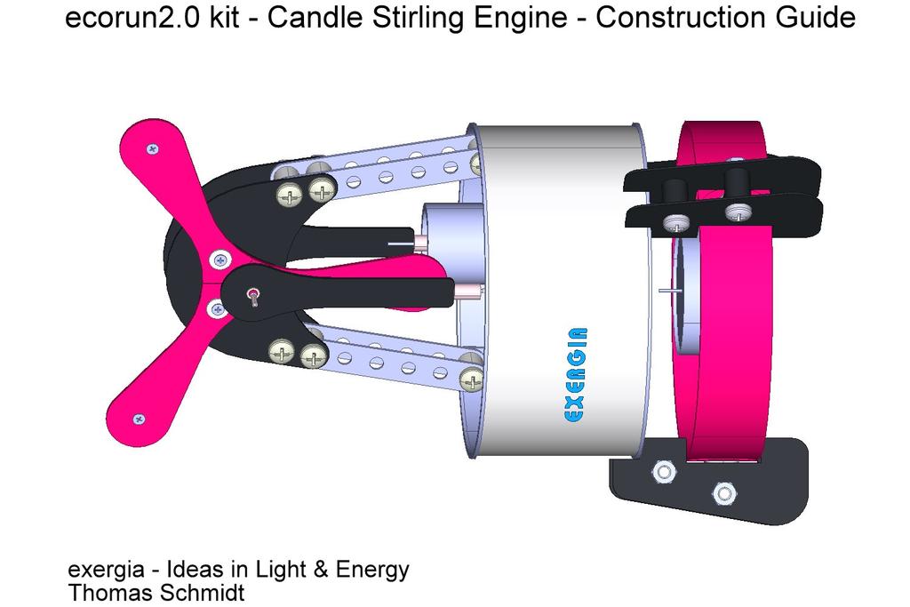
2 Construction Guide ecorun2.0 kit - Version.0 - Page 2 Safety Instructions Attention: The Stirling Engine ecorun2.0 is not a toy and not suitable for children under the age of 2. When running this engine use the same safety precautions as for open fire and flames. Never leave the engine running or the candle burning un-supervised. Never let a stopped engine heat for more than 3 minutes. Don't touch the engine's bottom cover - burn injury hazard. Exergia is not responsible for any damages or injury occurring during the operation of this engine. modern Stirling engine designs. The ecorun2.0 Stirling engine is an an extraordinary engine that demonstrates these concepts with the conversion of medium temperature heat into mechanical work. (2) Design The ecorun2.0 Stirling engine consists of five main units: Main working space 'Can' comprising top and bottom housing covers connected by a white cardboard ring Power piston A graphite piston running in an aluminium power cylinder directly connected to the main working space. () Introduction In the early days of the Industrial Revolution, the Edinburgh brothers James and Robert Stirling started working in 85 on a safer alternative to the established steam engines of the day. By using air instead of steam as the working fluid, the design avoided the then common risk of boiler explosion. The first patent in 86. The Stirling engine is a vastly different heat engine to the internalcombustion (diesel or petrol) engine in your car. It has the potential to use any heat source as "fuel including waste heat and solar energy. As the limits of fossil fuel resources became obvious, scientists and engineers revisited the Stirling principle as a way to exploit alternative energy sources. During the 980s Prof. I. Kolin (University of Zagreb) and others developed engines based on an adapted Stirling principle capable of operating with a temperature differential of less than 50 degrees Celsius, thus proving the feasibility of exploiting low temperature heat sources to power Displacer piston A foam disc inside the main working space. Crankshaft and propeller Two rods connect the crankshaft to the displacer and power piston the phase difference between the sinusoidal movement of the pistons is about 90 degrees. Rack with candle (3) Hints The kit includes all parts to assemble the engine. No gluing is required. Only common hand tools are required: Small screwdrivers (Philips Nº and Nº 2) 7mm (M4 nuts) and 4mm (M2 nuts) spanners are useful but not essential
3 Construction Guide ecorun2.0 kit - Version.0 - Page 3 (4) Assembly Small flat-nosed pliers Small hammer Craft knife (sharp!) for cutting and de-burring Sand paper for de-burring Additionally you should have at hand: A small piece of wood, like a child's brick, to press the power cylinder by hand into its ring. A few drops of thin mineral oil (Not vegetable oil!) The parts are packed in the main working space. Before starting to assemble the engine please carefully remove the top cover (with the black foam displacer on top) and carefully identify all the parts by name and part number given in the parts list. The parts come in six groups: Loose in the can - Parts (-8) One larger plastic bag - (A. - A.7) Five small plastic bags - B.-3, C.-5, D-5, E.-9, F.-2 The six stages for assembling the engine are in described in the paragraphs below. All steps that need extra care or additional tests of assembled units are marked with a in the text. Please carefully read through each stage before starting work, follow the tips and take your time. Only finger-tighten fasteners to begin with, only tighten properly when the instructions say so. For further information see: Have a lot of fun with the ecorun2.0 kit engine! (4.) The Candle Rack - see Fig. If necessary, push out from the back (white) any 'chads' left in the punched holes of the ring strips (5) and the disc (6). To each of the three long M4 screws (C.5), fit two washers (D.5) and a metal angle bracket (B.3). Lay the three ring strips on top of each other so that the holes are staggered by one position to line up one clearance hole (in the middle) through all three strips. Put one of the prepared screws into this hole and fit an M4 nut (D.2) to hold the strips in place. Now wrap the three strips into a ring. Be very careful as the cardboard strips are easily broken. You should get a multilayer ring assembly, with every strip starting with one end in the inner layer and its other (rounded) end in the outer layer. Fit the other two long M4 screws (C.5) with an M4 nut (D.2) each taking care to get the right orientation of the angle brackets (B.3). Attach three other angle brackets (B.3) to the disc (6) with a short M4 screw (C.3) and nut (D.2). Now fit the angle brackets on the disc over the three ends of the long M4 screws (C.5) that already hold the ring assembly together. Use two M4 nuts (D.2) for each bracket. Make sure that the inner M4 nuts are flush with the ends of the screws to make a proper seat for the tea light candle (9). Assemble two black supports (A.) to each angle bracket on the ring assembly. Use two medium M4 screws (C.4), two black distance pieces (B.2), two M4 nuts (D.2) for each bracket and don't forget one M4 washer (D.5) for the upper distance piece.
4 Construction Guide ecorun2.0 kit - Version.0 - Page 4 Now fit the candle (9) and the housing ring (3) with its bottom cover () into the rack, adjusting the supports and brackets so that everything fits well. Finally, tighten all screws and nuts. (4.2) The Top Cover - see Fig.2 Remove the power piston from its cylinder. With a craft knife and/or sand paper, carefully remove any burrs from the edges of the power cylinder (E.) and its ring (8). Very carefully clean all traces of dust from the power cylinder. Refit the piston and check that it glides smoothly inside the cylinder without noticeable friction or any sticking. Place the ring (7) on a hard flat surface and carefully push the power cylinder into it using hand pressure. Making sure that it stays vertical to avoid the cylinder jamming. A small piece of wood on top of the cylinder may help to increase hand pressure to push it down flush. Cut two 2mm long pieces of the medium sized flexible tube (E.7). Fix the last two angle brackets (B.3) on the top of the cover using long M2 screws (C.2), the medium sized M3 washer (D.4), the tube piece, the small M3 washer (D.3) and the M2 nut (D.). Take care that with the correct orientation of the brackets. Fit the power cylinder and ring to the top cover (2) using the four long M2 screws (C.2), the medium M3 washers (D.4) and the M2 nuts (D.). As a first step, only finger-tighten the nuts. Ensure that there is no gap between the ring and the top cover before final tightening the nuts. (4.3) Crankshaft Support Assembly - Fig.3a/b Fit four M4 x 6 screws (C.4) into the holes in one of the crankshaft support plates (A.2) and lay it on the table with the screw heads down. Fit two of the metal strips (A.5), the white distance pieces (B.), two more metal strips and the second support plate (A.2), fastening this stack with four M4 nuts (D.2). Attach this assembly to the metal angle brackets on the top cover with two more M4x6 screws (C.4), distance pieces (B.) and M4 nuts (D.2) in the highest position possible - see fig.3b. Tighten the two screws firmly. Fit the main axle of the large crank disc (E.) into the bushes. It must be horizontal, and perpendicular to each support plate (A.2). If not, adjust by slightly moving the supports relative to each other. Now final tighten the four screws and their nuts. The complete assembled upper structure should be perpendicular to the upper cover surface. If this is not the case carefully correct this by slightly bending the metal strips. (4.4) Propeller and Crank Disc Assembly - Fig.4 If necessary, push out from the back (white) any 'chads' left in the punched holes of the propeller blades A (A.6) and B (A.7). Fastened pairs of blades together - white sides face to face - with short M2 screws (C.), M3 washer (D.4) and the M2 nut (D.) to the crank disc (E.). Then fasten together each blade pair at their outer ends with M2 screws (C.) and nuts (D.) - no washers. Take care that each blade's surface is perpendicular to the
5 Construction Guide ecorun2.0 kit - Version.0 - Page 5 main axle. (4.5) Fitting and Adjustment of Crank Discs - Fig.5 The central hole in the small crank disc (E.2) has to be enlarged using the long pin (E.5) as a tool. With a small hammer, carefully drive the tool pin (E.5) into the central hole in the crank disc taking care that it is perpendicular to the disc. Using the pliers, carefully pull out the pin. Now turn the crank disc over and drive the short pin (E.3) into the outer hole. Cut two 2mm long pieces of the thin flexible tube (E.6) and fit one each to the axle and the pin of the large crank disc (E.). Put one of the small beads (E.9) on the axle and pass the axle through the bushes of the support assembly. Put another bead on the free end of the axle. Hold the large crank disc with one hand - grasp between the propeller blades. With your other hand, twist the small disc on to the axle. Ensure that the axle has about a half millimetre of end-play (float). Test the free running of the propeller. After a flick with your finger, it should continue to spin for about two seconds. Now it's time to adjust the off-set between the two crank discs. This provides the so-called 'phase difference', the correlation between the movement of the two pistons. It should be somewhere about 90 deg. Imagine the pins in the two crank discs as the hands of a clock. Looking at the propeller from the front, turn it until its crank pin is in the 2 o'clock position. Hold the large crank disc in this position, and twist the small crank disc until its pin is at 9 o'clock as seen from the same (propeller) end. Set like this, the engine will run clockwise. If you set the small crank disc's pin to 3 o'clock, the engine will run anti-clockwise. (4.6) The Connecting Rods - Fig.6 From the thin flexible tube (E.6), cut two 3mm lengths and two 8mm lengths. From the thick flexible tube (E.8), cut two 8mm lengths. Carefully push an 8mm lengths of (E.8) onto the narrow end of each connecting rod - the Power Piston Con Rod (A.4) the Displacer Piston Con Rod (A.3). Be very careful as you can easily break the cardboard. Insert the the medium sized pin (E.4) into the gap between the tube and the connecting rod (referenced to below as con rod tube and pin). The pins must protrude 5mm below the lower end of the con rods. Push an 8mm length of the thin flexible tube (E.6) about 4mm over the bare end of each pin (E.4). (4.6.) Power Piston Con Rod (PPC) Push pin of the power piston (F.2) about 3mm into the open end of the PPC tube; this should leave a gap inside the tube of about mm between the ends of the two pins. Insert the power piston into its cylinder. Fit a bead (E.9) onto the the pin of the small crank disc (E.2) followed by the head of the PPC and a second bead (E.2). Push a 3mm length of the thin flexible tube (E.6) onto the open end of the crank pin to stop the con rod coming off. Ensure that there is a slight gap (about half a millimetre) between the bead and the tube. Manually spin the propeller to test the free movement of the power piston. The power piston must not touch the top cover. If necessary readjust the PPC pin.
6 Construction Guide ecorun2.0 kit - Version.0 - Page 6 (4.6.2) Displacer Piston Con Rod (DPC) (5) Operating Instructions Now fit the top cover over the displacer piston (4) pin so that the piston will eventually be inside the working space (the 'can'). Push the displacer piston's pin about 3mm into the open end of the DPC's tube. Then finish assembling the DPC onto the propeller crank pin as you did with the PPC. The easiest way to fit the DCP onto the crank pin is to rotate the prop until the pin is in its uppermost position. Before starting, make sure that you're set up on a fireproof base in a dry and draft-free environment. The assembled displacer piston should have a minimum distance from the top cover of about one millimetre in its upper position. Check the free running of the propeller. If necessary readjust the propeller blades. Take care to orientate the con rods correctly. The pins must be on the side of the con rods that faces the support plates (A.2). (4.7) Closing the Housing and Lubrication Now carefully press the top cover (2) with the complete upper assembly into the housing ring. The engine has five bearing bushes: two bushes for the main axle in the support plates, two bushes in the connecting rods and one in the top cover to guide the displacer rod. Use a thin piece of wire or the long cylindrical pin (E.5) to apply a tiny drop of machine oil to each pin or axle where it goes through the bushes. Make sure that the oil goes into the bearing. DO NOT get any oil on the power piston or cylinder! Now your engine is ready for the first test run. Put the tea light candle into the rack, light the candle and fit the engine centred on top of the rack over the burning candle. After a minute or two, flip the prop in a clockwise direction (assuming you are looking toward the prop, see paragraph 4.5). The ecorun2.0 engine should start immediately and will run for more than thee hours - the burning time of the candle. Please note that the size of the candle flame may vary during burning resulting in the engine's speed varying anywhere between 200 and 600 rpm. The candle flame must never touch the surface of the lower housing cover. If necessary, shorten the candle's wick with a pair of scissors. (6) Troubleshooting If you can't get your engine to operate properly or not run at all, go through the following check list step by step, fixing any problems identified. (6.) Sealing of the Working Space The working space must be fairly air-tight. Normally all of the screwed and pressed connections should provide adequate sealing of the engine. To check there are no major leaks, remove the power piston con rod from its crank pin and see how fast the power piston sinks down the cylinder. Not much below two
7 Construction Guide ecorun2.0 kit - Version.0 - Page 7 seconds indicates adequate sealing of the engine. Critical points for the sealing are as follows: The screws holding the metal brackets onto the top cover. the retainers (E.6). (6.3) Free Running Pistons Tighten up the fastenings of the angle brackets. If necessary, remove the top cover. Reread the related hints in the paragraph 4.6 "Connecting Rods". Readjust pins and flexible tubes if needed. There is a small gap between the power cylinder ring and the If any moisture has entered the engine's working space (perhaps when checking for leaks), water may have condensed in the gap between the power piston and cylinder, causing the piston to stick. Disassemble the power piston together with its con rod and dry it. Leave it disassembled for a while so any residual moisture may evaporate. top cover. Try reassembling with the cylinder and ring rotated (90 or 80 deg) on the cover. If this does not help, fill the gap with some glue. There is a leakage between the power cylinder and its ring. Fill the gap with some glue If the top cover has been removed from the housing ring several times, there may be a poor seal between cover and ring. Fill the gap with glue. Beware: after doing this you won't be able to remove the top cover again. If necessary you may open the housing from the bottom side. If you have problems locating the leakage, put a drop of washingup liquid in a little water and apply sparingly to the places above in question. Manually rotate the propeller. Little bubbles will show where air is leaking. Make sure you dry the engine properly. (6.4) Crank Phase Difference The movement of the two pistons must be approximately 90º out of phase. Reread the paragraph 4.5 "The Connection and Adjustment of the Crank Discs". Readjust the small crank disc if needed. (6.5) Engine Heating To ensure sufficient heating, the candle flame needs to be at least 0 to 5 millimetres high. If necessary, replace the candle. (6.2) Mechanical Friction A draft-free environment is essential to ensure optimal heat transfer from the candle flame to the bottom housing cover. Reread all hints in this guide that relate to free running and axial play. In particular that: (7) Credits There is not enough axial play on the main axle. Carefully pull the small crank disc slightly (a few tenths of a millimetre) along the main axle away from the support plate. Many thanks to Guy Attfield for the help with this English version of the construction guide. The con rods do not move freely on the crank pins. Readjust
8 Construction Guide ecorun2.0 kit - Version.0 - Page 8 Fig. Assembly of the Candle Rack
9 Construction Guide ecorun2.0 kit - Version.0 - Page 9 Fig.2 - Assembly of the Top Cover
10 Construction Guide ecorun2.0 kit - Version.0 - Page 0 Fig.3a - Assembly of the Support Structure of the Crankshaft
11 Construction Guide ecorun2.0 kit - Version.0 - Page Fig.3b - Connection of Support Element to Top Cover
12 Construction Guide ecorun2.0 kit - Version.0 - Page 2 Fig.4 - Connection of the Propeller Blades to the Crank Disc
13 Construction Guide ecorun2.0 kit - Version.0 - Page 3 Fig.5 - Connection and Adjustment of the Crank Discs
14 Construction Guide ecorun2.0 kit - Version.0 - Page 4 Fig.6 - Connection of the Connecting Rods to the Pistons
15 Construction Guide ecorun2.0 kit - Version.0 - Page 5 Parts list (Number Part Quantity) C.3 Cheese-head Screw, M4 x 5, short 3 Housing cover, bottom C.4 Cheese-head Screw, M4 x 6, medium 2 2 Housing cover, top C.5 Cheese-head Screw, M4 x 35, long 3 3 Housing ring D. Nut, M2 2 4 Displacer piston with rod D.2 Nut, M Ring strips, rack 3 D.3 Washer M2, Ø inner=2,2mm, small 2 6 Disc, rack D.4 Washer M3, Ø inner=3,2mm, medium 9 7 Power cylinder ring D.5 Washer, M4, Ø inner=4,2mm, large 9 8 Tea light candle, Fuel E. Crank disc with main axle and pin, large A. Support, rack 6 E.2 Crank disc, small A.2 Support plate, crankshaft 2 E.3 Pin x2, short A.3 Displacer Piston Con-rod (DPC), long E.4 Pin x6, medium 2 A.4 Power Piston Con-rod (PPC), short E.5 Tool, Pin x26, long A.5 Metal strip, 7 holes 4 E.6 A.6 Propeller blade A (2 holes) 4 Flexible tube, outer diameter.6mm, Length~30mm, thin wall, to be cut: 2x 2mm, 2x 3mm, 2x 8mm A.7 Propeller blade B (3 holes) 2 Flexible tube, outer diameter 4.5mm, Length~0mm, medium wall, to be cut: 2x 2mm B. Distance piece, white, 8mm 6 B.2 Distance piece, black, mm 6 Flexible tube, outer diameter 5mm, Length~30mm, thick wall, to be cut: 2x 8mm B.3 Metal angle bracket 8 E.9 Bead, spacer 6+2 C. Flat-head Screw, M2 x 4, short 6 F. Power cylinder C.2 Flat-head Screw, M2 x 6, long 6 F.2 Power piston with pin E.7 E.8

16 Construction Guide ecorun2.0 kit - Version.0 - Page 6
Working Stirling-Motor
 PARTS LIST 113.174 Working Stirling-Motor Please Note The OPITEC range of projects is not intended as play toys for young children.they are teaching aids for young people learning the skills of Craft,
Stirling Engine. What to Learn: A Stirling engine shows us how energy is converted and used to do work for us. Materials
 Stirling Engine Overview: The Stirling heat engine is very different from the engine in your car. When Robert Stirling invented the first Stirling engine in 1816, he thought it would be much more efficient
Assembly Instructions: Conventional Motor (Beakman's Motor Kit)
") Assembly Instructions: Conventional Motor (Beakman's Motor Kit) 1. Leave about 3" (7-8cm) and wind the wire 10-35 times around the AA battery. You do not have to be neat as some randomness does not affect
Assembly Instructions: Conventional Motor (Beakman's Motor Kit) 1. Leave about 3" (7-8cm) and wind the wire 10-35 times around the AA battery. You do not have to be neat as some randomness does not affect
Contents. Preparing the motor Winding the rotating secondary Winding the primary... 8
 120732-130389 Propeller Clock Construction Notes Revision E, December 2, 2013 Contents Preparing the motor... 2 Winding the rotating secondary... 5 Winding the primary... 8 UltiProp Clock (Elektor Dec.
Safety, Operation and Maintenance Instructions For Long & Short Nose Upholstery Air Stapler (NS10 & NS11)
") Safety, Operation and Maintenance Instructions For Long & Short Nose Upholstery Air Stapler (NS10 & NS11) Important: Drop 3 drops of oil into the stapler air inlet BEFORE first use. See page 2. Please
Safety, Operation and Maintenance Instructions For Long & Short Nose Upholstery Air Stapler (NS10 & NS11) Important: Drop 3 drops of oil into the stapler air inlet BEFORE first use. See page 2. Please
FRP Ball Valves INSTALLATION & MAINTENANCE MANUAL
 FRP Ball Valves INSTALLATION & MAINTENANCE MANUAL FRP BALL VALVES TABLE OF CONTENTS MAINTENANCE AND INSTALLATION INSTRUCTIONS 1. 2. 2.1 2.2 2.3 2.4 GENERAL...Page 1 HANDLING...1 Receiving and Storing...1
Bag 1. Bag 1. Center Pivot. Center Pivot
 8 00734 01901 5 Center Pivot Bag 1 3374 - Center Pivot Socket 4019 - Alum Pivot ball 3254-2-56 Button Head *Note - Sometimes it is helpful to slightly over-tighten the top clamp screws, then work the ball
$1.00 FOR THE TQIO/RCIO
 $1.00 FOR THE TQIO/RCIO m mm HDBBYSHOP Champion Jay Halsey has an impressive track record. One of Jay's advantages is a whisper smooth tranny thanks to his dad, Jim. Now you can build a Halsey transmission!
Installation Instructions
 Preparing your vehicle to install your brake system upgrade 1. Rack the vehicle. 2. If you don t have a rack, then you must take extra safety precautions. 3. Choose a firmly packed and level ground to
Rear End Installation and Bearing Kit - 8.8in (86-12 V8; V6)
") Rear End Installation and Bearing Kit - 8.8in (86-12 V8; 11-13 V6) Tools Required: Jack Stands 5 Floor Jack 2 Oil Pans 1 Wheel Blocks 2 Differential Oil 3 qts Friction Modifier 3 bottles Tube of Black
Rear End Installation and Bearing Kit - 8.8in (86-12 V8; 11-13 V6) Tools Required: Jack Stands 5 Floor Jack 2 Oil Pans 1 Wheel Blocks 2 Differential Oil 3 qts Friction Modifier 3 bottles Tube of Black
Clutch Installation Guide
 Clutch Installation Guide 0 STOP! READ CAREFULLY BEFORE INSTALLING CLUTCH This clutch must be installed by a qualified installer. Improper installation or failure to replace or resurface the flywheel,
DIY Bi-Metallic Strip
 DIY Bi-Metallic Strip An introduction to the applications of thermal expansion and two-way switching. Written By: Mahaaveer BN 2018 Page 1 of 14 INTRODUCTION A bi-metallic strip is used to convert a temperature
Bachmann GWR Earl (Dukedog) EM Finescale Conversion
 EM Finescale Conversion") Bachmann GWR Earl (Dukedog) EM Finescale Conversion Before you start, it is a good idea to have some small containers or snap top poly bags to put screws and components in for safe keeping...much better
Bachmann GWR Earl (Dukedog) EM Finescale Conversion Before you start, it is a good idea to have some small containers or snap top poly bags to put screws and components in for safe keeping...much better
G&G GR14 Airsoft Reassembly
 G&G GR14 Airsoft Reassembly This Guide will show you the right technique for proper and fast assembly. Written By: 101 Tech USA ifixit CC BY-NC-SA www.ifixit.com Page 1 of 16 INTRODUCTION The G&G m-14
ORIGA SYSTEM PLUS Guides, Brakes and Valves for Modular Linear Drive Systems OSP Appendix to the Operating Instructions
 ORIGA SYSTEM PLUS Guides, Brakes and Valves for Modular Linear Drive Systems OSP Appendix to the Operating Instructions TAll personnel who have anything to do with the OSP fitted with guides, brakes or
INSTALLATION GUIDE. KTM RFS Husaberg Polaris 450/525 Outlaw KTM 450/525 XC ATV Manual Revision:
 REKLUSE MOTOR SPORTS The z-start Pro Clutch INSTALLATION GUIDE KTM RFS 03-07 Husaberg Polaris 450/525 Outlaw KTM 450/525 XC ATV 191-833 Manual Revision: 010615 2002 Rekluse Motor Sports Rekluse Motor Sports,
CALIFORNIA TRIMMER MOWER MAINTENANCE MANUAL
 CALIFORNIA TRIMMER MOWER MAINTENANCE MANUAL 2 Table of Contents Section 1: General Information Page Handle Assembly Instructions 4 Maintenance All Models 6 Oil Change Procedures All Models 9 Height Adjustment
Fluid-O-Tech ROTOFLOW ROTARY VANE PUMP REBUILD MANUAL
 Fluid-O-Tech PUMP TECHNOLOGY AT ITS BEST WWW.FLUID-O-TECH.COM Office: 161 Atwater St., Plantsville, CT 06479 Phone: (860) 276-9270 Fax: (860) 620-0193 ROTOFLOW ROTARY VANE PUMP REBUILD MANUAL 08/09 Ed.,
Bob's Card Model and [Resources]
![Bob's Card Model and [Resources]](/thumbs/89/98424237.jpg "Bob's Card Model and [Resources]") Bob's Card Model www.bobscardmodels.altervista.org and www.zealot.com [Resources] Conair C S 2F (Tracker) water-bomber(1:144) Securité Civile's converted Tracker, used for patrol duty, but also for water-bombing
Bob's Card Model www.bobscardmodels.altervista.org and www.zealot.com [Resources] Conair C S 2F (Tracker) water-bomber(1:144) Securité Civile's converted Tracker, used for patrol duty, but also for water-bombing
PYRTE. Building The Front Axle, Fork and Steering
 PYRTE Building The Front Axle, Fork and Steering The front axle on this traction engine is a very simple affair, in that it is a rectangular steel rod, sat on edge, with a pivot in the centre, which is
S1 Sequential. T56 Magnum. Sequential shifter. Contents and assembly instructions
 S1 Sequential Sequential shifter T56 Magnum Contents and assembly instructions Parts List Sequential shifter x1 Base plate x1 Base spacer x1 Drill Square x1 Shaft fitting x1 Square washer x1 8mm Aluminium
INSTALLATION INSTRUCTIONS PERFORMANCE AT THE WHEELS KIT W125
 INSTALLATION INSTRUCTIONS PERFORMANCE AT THE WHEELS KIT W125 1968-81 CAMARO & FIREBIRD 10 & 12 BOLT W/"C" CLIPS Thank you for choosing STAINLESS STEEL BRAKES CORPORATION for your braking needs. Pleases
Self-Adjust Clutch Installation Guide
 Self-Adjust Clutch Installation Guide 0 STOP! READ CAREFULLY BEFORE INSTALLING CLUTCH This clutch must be installed by a qualified installer. Improper installation or failure to replace or resurface the
Inside a typical car engine. Almost all cars today use a reciprocating internal combustion engine because this engine is:
 Tech Torque HOW PETROL ENGINES WORK The Basics The purpose of a gasoline car engine is to convert gasoline into motion so that your car can move. Currently the easiest way to create motion from gasoline
3D PRINTER. Pack 09. Anything you can imagine, you can make! 3D technology is now available for you at home! BUILD YOUR OWN
 BUILD YOUR OWN Pack 09 Anything you can imagine, you can make! 3D PRINTER Compatible with Windows 7 & 8 Mac OS X 3D technology is now available for you at home! www.model-space.com BUILD YOUR OWN 3D PRINTER
I n s t r u c t i o n M a n u a l. Instruction Manual SPECIFICATION
 I n s t r u c t i o n M a n u a l Instruction Manual SPECIFICATION - Wingspan: 3200mm (125,9 in) - Length: 1650mm (64,9 in) - Flying weight: 3000gr 3200gr - Wing area: 64.5 dm2 - Wing loading: 46g/dm2
INSTALLATION INSTRUCTIONS
 INSTALLATION INSTRUCTIONS REAR DISC CONVERSION KIT A126-2 1988-98 C1500 2WD 10" REAR DRUM Thank you for choosing STAINLESS STEEL BRAKES CORPORATION for your braking needs. Pleases take the time to read
INSTALLATION, OPERATION AND MAINTENANCE Threaded and Wafer Style Flowmeters
 INSTALLATION, OPERATION AND MAINTENANCE Threaded and Wafer Style Flowmeters Table of Contents Page 1. Principle of Operation...2 2. Installation Planning......2 3. Installation...3 3.1 Safety Considerations...
INSTALLATION INSTRUCTIONS
 INSTALLATION INSTRUCTIONS REAR DISC BRAKE CONVERSION KIT A125-2 1955-70 FULL SIZE CHEVROLET Thank you for choosing STAINLESS STEEL BRAKES CORPORATION for your braking needs. Pleases take the time to read
INSTALLATION INSTRUCTIONS REPAIR SEAL KIT PowerSurvivor 40E
 INSTALLATION INSTRUCTIONS REPAIR SEAL KIT PowerSurvivor 40E PURPOSE OF THE KIT The Repair Seal Kit should be installed after 1000 hours of operation. It should be installed regardless of whether or not
 CONTENTS Contents and Cautions 2 Stirling Engine 3 Before Assembling the Kit 4 1. Assembling the Stand 5 2. Attaching Wheels to the Body 7 3. Attaching the Cylinder to the Body 8 4. Assembling the Lever
INSTALLATION INSTRUCTIONS
 INSTALLATION INSTRUCTIONS REAR DISC BRAKE CONVERSION KIT A126-1 1973-87 CHEVROLET 1/2 TON 2WD Thank you for choosing STAINLESS STEEL BRAKES CORPORATION for your braking needs. Pleases take the time to
Hornby 08 Diesel Shunter EM Finescale Conversion.
 Hornby 08 Diesel Shunter EM Finescale Conversion. Before you start, it is a good idea to have some small containers or snap top poly bags to put screws and components in for safe keeping...much better
INSTALLATION INSTRUCTIONS
 INSTALLATION INSTRUCTIONS REAR DISC BRAKE CONVERSION KIT A125-3 1965-72 GM A-BODY 10 & 12 BOLT AXLES Thank you for choosing STAINLESS STEEL BRAKES CORPORATION for your braking needs. Pleases take the time
Re-Energy.ca - Solar Electricity - Build Your Own Solar Car
 Backgrounder Build Your Own Solar Car Back to Page 1 Build It! These step-by-step instructions provide you with a plan for making a basic solar car. If you can think of ways to improve the design of your
Torqueflite Manual/Automatic Valve Body
 TCI 122400 Torqueflite Manual/Automatic Valve Body This valve body can be installed in a few hours by carefully following directions. Read all instructions first to familiarize yourself with the parts
The Stirling Engine Assembly Instructions
 Klaus Hünig The Stirling Engine Assembly Instructions handle axe-bearing frame axle bearing crankshaft stand piston rod fly wheel stand main cylinder lid working piston working cylinder main cylinder wall
SERVICE MANUAL ULTIMATE 200
 SERVICE MANUAL ULTIMATE 200 This manual is for: 20 200-120 Ultimate 200 std. 120V 60 Hz 20 200-240 Ultimate 200 std. 240V 50 Hz 20 201-120 Ultimate 200 DMX 120V 60 Hz 20 201-240 Ultimate 200 DMX 240V 50
1 Green Pressure Regulator Spring Automatic transmissions operate at temperatures between 150ºF and
 Installation Instructions for 603107 Valve Body Kit C-4 1970 & Later Tools Required Speed Handle or Ratchet 3/8 Drive 1/2 Socket 3/8 Drive 7/16 Socket 3/8 Drive 5/16 Socket 3/8 Drive Small Screwdriver
26 Hume Reserve Court, Nth. Geelong, 3215 Phone: (03) Fax: (03) DUAL RANGE HIGH SPEED INSTALLATION MANUAL. for
 Fax: (03) DUAL RANGE HIGH SPEED INSTALLATION MANUAL. for") 26 Hume Reserve Court, Nth. Geelong, 3215 Phone: (03) 5272 2844 Fax: (03) 5272 2633 GEARLESS CENTRE DIFFERENTIAL FULL-TIME 4X4 TRANSFER CASE CONVERSION DUAL RANGE HIGH SPEED INSTALLATION MANUAL for TOYOTA
26 Hume Reserve Court, Nth. Geelong, 3215 Phone: (03) 5272 2844 Fax: (03) 5272 2633 GEARLESS CENTRE DIFFERENTIAL FULL-TIME 4X4 TRANSFER CASE CONVERSION DUAL RANGE HIGH SPEED INSTALLATION MANUAL for TOYOTA
Assembly Manual. 1/10th World GT car
 Assembly Manual 1/10th World GT car Center Pivot Bag 1 3374 - Center Pivot Socket 40194 - Hard Anodized Alum Pivot ball 3254-2-56 Button Head *Note - Sometimes it is helpful to slightly over-tighten the
Installation Instructions Z-Gate Shifter
 Installation Instructions Z-Gate Shifter Part Number 80681 1998, 2001 by B&M Racing and Performance Products The B&M Z-Gate shifter can be used in vehicles equipped with most popular three speed automatic
INSTALLATION INSTRUCTIONS
 INSTALLATION INSTRUCTIONS REAR DISC BRAKE CONVERSION KIT A157 1991-2004 Dodge Dakota 2WD 1991-2002 Dodge Dakota 4WD 1998-2002 Dodge Durango Thank you for choosing STAINLESS STEEL BRAKES CORPORATION for
INSTALLATION INSTRUCTIONS
 INSTALLATION INSTRUCTIONS PERFORMANCE AT THE WHEELS KIT W125-42 GM 10 & 12 Bolt Rear Axles with Staggered or non-staggered Shocks with C-Clips Thank you for choosing STAINLESS STEEL BRAKES CORPORATION
Disc Brake System ( For Cross-Country)
") Technical Service Instructions General Safety Information Disc Brake System ( For Cross-Country) SI-8C60F t WARNING Please use extra caution to keep your fingers away from the rotating disc brake rotor
Technical Service Instructions General Safety Information Disc Brake System ( For Cross-Country) SI-8C60F t WARNING Please use extra caution to keep your fingers away from the rotating disc brake rotor
Installation Instructions COMPETITION/PLUS SHIFTER Ford Mustang MT82 6-Speed Manual Transmission Catalog#
 Installation Instructions COMPETITION/PLUS SHIFTER 2015-2017 Ford Mustang MT82 6-Speed Manual Transmission Catalog# 3916037 Rev. 00 WORK SAFELY! For maximum safety, perform this installation on a clean,
POWER STEERING PUMP REBUILDING SPK101 Read instructions completely before removal & disassembly
 POWER STEERING PUMP REBUILDING SPK101 Read instructions completely before removal & disassembly DISASSEMBLY: 1. Remove pump from car and allow to drain. 2. Remove pulley from front of pump. This requires
Bruce s Science workbench
 Baby Vandegraff Generator by Bruce Yeany 2001 https://www.youtube.com/watch?v=parq01q DKe4 http://www.instructables.com/id/van-de- Graaff-Electrostatic-High-Voltage- Generator/ https://www.youtube.com/watch?v=esz
Prusa i3 Printer Assembly Guide
 Prusa i3 Printer Assembly Guide Special thanks to Carlos Sanchez and Miguel Sanchez for the graphics. All graphics captured from their great animation: http://www.carlos-sanchez.com/ Prusa3/ For copyright
LIMITED SLIP DIFFERENTIAL INSTALLATION
 Installation of the limited slip gear can be done with axle out of car or with car lifted to gain access from underneath. Refer to repair manual for proper lifting instructions if car is to be lifted.
Section 7 - Supplements
 SECTION 4 - FUEL SYSTEM REPAIRS 4.5 STEALTH / SHADOW BURNER (ADDITIONAL) 4.5.9 Valve Seal replacement 4.5.9.1 General Information The text of this supplement is written for competent persons who are familiar
Mamod SL1K Locomotive Assembly Instructions
 Mamod SL1K Locomotive Assembly Instructions LOCOMOTIVE ASSEMBLY INSTRUCTIONS To ensure ease of construction reference to these instructions are essential. All the major parts are in the front of the box
Suzuki GS1000G fork seal replacement
 Suzuki GS1000G fork seal replacement Before you start you require: 1) To read workshop service manual for your model 2) Socket allen key M8 3) Torque wrench 4) Special tool to hold inner, make your own,
INSTALLATION INSTRUCTIONS
 INSTALLATION INSTRUCTIONS REAR DISC CONVERSION KIT A136-1 1976-86 AMC 20 AXLES WITH WARN FULL FLOATING AXLE CONVERSION Thank you for choosing STAINLESS STEEL BRAKES CORPORATION for your braking needs.
Tri-Spark Ignition System Installation Triple Cylinder TRI-0001
 Tri-Spark Ignition System Installation Triple Cylinder TRI-0001 There are potentially lethal high voltages produced at the ignition coils and spark plugs, therefore every precaution must be taken to prevent
Solar Trike w i t h A C C U b a t t e r y d r i v e a n d LED lighting
 1.693 Solar Trike w i t h A C C U b a t t e r y d r i v e a n d LED lighting Necessary materials Fretsaw with metalworking blade drills. dia. 3,, 6, 7, Machine vice with soft jaws Soldering iron, solder
HOT-AIR ENGINE. Page 1
 Page 1 The pretty little toy about to be described is interesting as a practical application to power-producing purposes of the force exerted by expanding air. It is easy to make, and, for mere demonstration
MANUAL TRANSMISSION SERVICE
 MANUAL TRANSMISSION SERVICE Introduction Internal combustion engines develop very little torque or power at low rpm. This is especially obvious when you try to start out in direct drive, 4th gear in a
SAI GM Series Piston Hydraulic Motor Crankshaft Design Radial Piston Motors
 SAI GM Series Piston Hydraulic Motor Crankshaft Design Radial Piston Motors www.chinawinches.cn (Dimension: inch) Brief Performance Table of Sai GM Series Piston Hydraulic Motor (Full range GM05- GM9 series)
Marzocchi Suspension D-Street 24" D-Street 24" Technical instructions
 Technical instructions Exploded view - D-Street 24" 80 Rif. Code Quantity D-Street 24" 80 - Oil levels Position Oil type Quantity (cc) Right fork leg SAE 7,5-550013 185 Left fork leg SAE 7,5-550013 185
INSTALLATION INSTRUCTIONS
 INSTALLATION INSTRUCTIONS REAR CONVERSION KIT A111-2 (FORD 8" & 9" SMALL BEARING) & REAR CONVERSION KIT A111-3 (FORD 9 TORINO) Thank you for choosing STAINLESS STEEL BRAKES CORPORATION for your braking
Heavy Duty Miniature Quick-Change Applicator (End-Feed Type) with Mechanical or Air-Feed Systems
 with Mechanical or Air-Feed Systems") Heavy Duty Miniature Quick-Change Applicator (End-Feed Type) with Mechanical or Air-Feed Systems Instruction Sheet 408-8039 02 JUN 16 Rev G Ram Post Wire Disc Insulation Disc Insulation Crimper Stripper
Heavy Duty Miniature Quick-Change Applicator (End-Feed Type) with Mechanical or Air-Feed Systems Instruction Sheet 408-8039 02 JUN 16 Rev G Ram Post Wire Disc Insulation Disc Insulation Crimper Stripper
deutsch Taifun GT II Bedienungsanleitung User Manual english
 Taifun GT II Bedienungsanleitung deutsch User Manual english english Taifun GS II User Manual IMPORTANT Please read these instructions carefully, before using your Taifun GT II rebuildable tank atomizer.
MGA Gearbox Conversion Kit. Fitting Instructions
 MGA Gearbox Conversion Kit Fitting Instructions KIT CONTENTS Mazda MX-5 5 Speed Transmission: Vitesse Gearbox Case Vitesse Bellhousing Vitesse Machined Front Plate Modified rear case to accept Mazda mechanical
De clunking your MGB rear axle. By Stuart Clarke
 De clunking your MGB rear axle By Stuart Clarke Do you have that annoying clunking noise when accelerating or decelerating, or even when you lift off to change gear, well it s possible to resolve the issue
Tools Required. Metric Wrench Set Screwdriver Set Metric Socket Set Pliers Heavy duty hydraulic Jack and Car Stands Box knife or similar Hacksaw WD40
 Subaru 2004+ Legacy GT & Outback XT For JDM 2.0 twinscroll turbo and USDM 2.5 turbo models Front Mount Intercooler Fitting Instructions PN# LEG-1348-000 You are now the proud owner of a highly tested and
Next, chase the threads in the lower A-arm mounts with the 5/8-18 tap and blowout any remaining particles.
 Next, chase the threads in the lower A-arm mounts with the 5/8-18 tap and blowout any remaining particles. Now, apply some anti-seize to the threads of the pivot stud. Also put anti-seize inside the bore
Installation instructions, accessories - Rear Seat Entertainment
 XC90 Section Group Weight(Kg/Pounds) Year Month 3 39 2004 10 XC90 2003, XC90 2004, XC90 2005, XC90 2006, XC90 2007, XC90 2008 Replaces issue: 2003 12 J3904620 Page 1 of 18 Required tools A0000162 A0000163
INSTALLATION INSTRUCTIONS
 INSTALLATION INSTRUCTIONS REAR DISC BRAKE CONVERSION KIT A158 1994-97 Dodge Ram 1500 (2WD & 4WD) and REAR DISC BRAKE CONVERSION KIT A158-1 1998-01 Dodge Ram 1500 (2WD & 4WD) Thank you for choosing STAINLESS
Assembly Manual. 1/10th Formula 1 Car
 Assembly Manual 1/10th Formula 1 Car Center Pivot Bag 1 3374 - Center Pivot Socket 40194 - Hard Anodized Alum Pivot ball 3254-2-56 *Note - Sometimes it is helpful to slightly over-tighten the top clamp
OWNER S MANUAL G620PU-1 MODEL: G620PU WARNING 848H4893A3 (704)
") 848H4893A3 (704) OWNER S MANUAL MODEL: G620PU G620PU-1 WARNING Do not modify any parts of the engine. This engine is designed to be used to Radio controlled products. In case any modification by customer,
848H4893A3 (704) OWNER S MANUAL MODEL: G620PU G620PU-1 WARNING Do not modify any parts of the engine. This engine is designed to be used to Radio controlled products. In case any modification by customer,
INSTALLATION GUIDE CRF150R Manual Revision:
 REKLUSE MOTOR SPORTS The z-start Pro Clutch INSTALLATION GUIDE CRF150R 191-810 Manual Revision: 032508 2002 Rekluse Motor Sports Rekluse Motor Sports, Inc. 110 E. 43rd Street Boise, Idaho 83714 208-426-0659
Written By: Markus. Step-by-Step guide how to replace a dead NICD-Battery with LiFePO-Batteries. Rollei 6000/6008 Battery LiFePO4 Replacement
 Rollei 6000/6008 Battery LiFePO4 Replacement Step-by-Step guide how to replace a dead NICD-Battery with LiFePO-Batteries. Written By: Markus ifixit CC BY-NC-SA www.ifixit.com Page 1 of 18 INTRODUCTION
INSTALLATION INSTRUCTIONS
 INSTALLATION INSTRUCTIONS REAR DISC CONVERSION KIT A128-4 1997-2004 JEEP WRANGLER (TJ) WITH DANA 44 AXLES (non-abs) Thank you for choosing STAINLESS STEEL BRAKES for your braking needs. Pleases take the
INSTALLATION GUIDE. KTM 125, 144, Stroke KTM 250, Stroke KTM 250 SXF, XC, XC-W KTM 450, 505 SXF Manual Revision:
 REKLUSE MOTOR SPORTS The z-start Pro Clutch INSTALLATION GUIDE KTM 125, 144, 200 2-Stroke KTM 250, 300 2-Stroke KTM 250 SXF, XC, XC-W KTM 450, 505 SXF 191-836 Manual Revision: 050307 2002 Rekluse Motor
SERIES A & AA ROLLER DOORS INSTALLATION GUIDE
 SERIES A & AA ROLLER DOORS INSTALLATION GUIDE THESE INSTRUCTIONS ARE PROVIDED FOR USE BY EXPERIENCED INSTALLERS OF GARAGE DOORS BY UNDER-TAKING THE INSTALLATION OF THIS DOOR, THE INSTALLER UNDERSTANDS
INSTRUCTIONS FOR INSTALLATION OF THE CH-2 and CH-3 DRIVE UNIT TO AN ENGINE WARNING
 INSTRUCTIONS FOR INSTALLATION OF THE CH-2 and CH-3 DRIVE UNIT TO AN ENGINE WARNING! Never reach hands or other body parts in or near moving parts!! Maintain a safe distance from any fixed or moving propeller!!
INSTALLATION INSTRUCTIONS
 INSTALLATION INSTRUCTIONS PERFORMANCE AT THE WHEELS KIT W155-5 CHRYSLER 8 3 /4" & 9 3 /4" REAR AXLES Thank you for choosing STAINLESS STEEL BRAKES CORPORATION for your braking needs. Please take the time
INSTALLATION INSTRUCTIONS R1 REAR CONVERSION KIT
 INSTALLATION INSTRUCTIONS R1 REAR CONVERSION KIT INSTRUCTION FOR ASSEMBLY OF JEEP CJ SERIES W/AMC 20 REAR AXLES, 5 x 5-1/2" BOLT CIRCLE WITH A130-4 FULL FLOATING AXLE OR A130-5 (1 PIECE AXLE) Thank you
Butterfly Valve Type 57P
 Butterfly Valve Type 57P Contents Lever Type: 50-200 mm (2-8 ) Body Material: CPVC Gear Type: 50-200mm (2-8 ) Body Material: CPVC (1) Be sure to read the following warranty clauses of our product 1 (2)
Gearbox Assembly 101. Introduction. Before Beginning. By Mark Schutzer 4/13/06
 Gearbox Assembly 101 By Mark Schutzer 4/13/06 Introduction If you are planning to re-motor an old brass locomotive you may want to upgrade to a new gearbox at the same time. The early 60 s and 70 s gearboxes
RECOMMENDED MOTOR AND BATTERY SET UP
 SPECIFICATION - Wingspan: 6000mm (236.2 in) - Length: 2873mm (113.1 in) - Flying weight: 14-18 kg - Wing area: 219.4 dm2 - Wing loading: 64g/dm2 - Wing type: HQ airfoils - Covering type: Genuine ORACOVER
Installation Instructions for disc brakes
 Installation Instructions for disc brakes Bedford CF 230-280, built 1974-1986, not suitable for vehicles with rear twin tyres Included 2 pcs. Wheel Hubs with Wheel Bolts, Mounted Brake Discs and Wheel
INSTALLATION INSTRUCTIONS
 INSTALLATION INSTRUCTIONS REAR DRUM TO DISC BRAKE CONVERSION KIT A118 pre-1985 Ford F150 (except 1983-1984 w/super H/D axle) Thank you for choosing STAINLESS STEEL BRAKES CORPORATION for your braking needs.
CHEVROLET TAHOE/DENALI/AVALANCHE/YUKON/ SILVERADO/SIERRA 2007+
 CHEVROLET TAHOE/DENALI/AVALANCHE/YUKON/ SILVERADO/SIERRA 2007+ INSTALLATION INTRODUCTION 1. REMOVING THE FENDER AND DOORS FROM THE A-PILLAR AND DISCONNECTING THE WIRE HARNESS @ THE DOOR JAM 2. REMOVING
Installing Tapered Steering Head Bearings Steering head bearings are basically the hinge at the front of your bike that lets you turn the handlebars
 Installing Tapered Steering Head Bearings Steering head bearings are basically the hinge at the front of your bike that lets you turn the handlebars to point the front wheel in the direction you want to
13. CRANKCASE/CRANKSHAFT/BALANCER/PISTON/CYLINDER
 13. CRANKCASE/CRANKSHAFT/BALANCER/PISTON/CYLINDER COMPONENT LOCATION 13-2 SERVICE INFORMATION 13-3 TROUBLESHOOTING 13-4 CRANKCASE SEPARATION 13-5 CRANKSHAFT 13-7 MAIN JOURNAL BEARING 13-9 CRANKPIN BEARING
MECHANISMS. AUTHORS: Santiago Camblor y Pablo Rivas INDEX
 MECHANISMS AUTHORS: Santiago Camblor y Pablo Rivas INDEX 1 INTRODUCTION 2 LEVER 3 PULLEYS 4 BELT AND PULLEY SYSTEM 5 GEARS 6 GEARS WITH CHAIN 7 WORM GEAR 8 RACK AND PINION 9 SCREW AND NUT 10 CAM 11 ECCENTRIC
Sachs shock manual. ( ) 2 & 4 Stroke RR Enduro. ( ) RS Dual Sport
 2 & 4 Stroke RR Enduro. ( ) RS Dual Sport") Sachs shock manual (2013 2015) 2 & 4 Stroke RR Enduro (2014-2015) RS Dual Sport 1 Introduction The procedures in this manual must take place in a clean environment using professional tools and some specific,
Sachs shock manual (2013 2015) 2 & 4 Stroke RR Enduro (2014-2015) RS Dual Sport 1 Introduction The procedures in this manual must take place in a clean environment using professional tools and some specific,
Bow Extension Cylinders
 Bow Extension Cylinders Level of difficulty: Fairly easy to intermediate very rewarding! Requires some patience. Tools needed: - 5-mm Allen wrench or socket (only for 90-95 models) - Needle nose pliers
Calandra Racing Concepts
 Calandra Racing Concepts Carpet Knifeä Version 3 Assembly and Setup Manual Congratulations! You now own the best 1/12th scale car on the market today, the Carpet Knifeä Version 3. This completely new car
INSTALLATION INSTRUCTIONS
 INSTALLATION INSTRUCTIONS REAR DISC BRAKE CONVERSION KITS A112, A112-1 & A112-93 1979-93 FORD MUSTANG with 7.5" & 8.8" AXLES Thank you for choosing STAINLESS STEEL BRAKES CORPORATION for your braking needs.
MATCHLESS SPINNING WHEEL
 MATCHLESS SPINNING WHEEL Single Treadle to Double Treadle Conversion Instructions Find out more at schachtspindle.com Schacht Spindle Company 6101 Ben Place Boulder, CO 80301 p. 303.442.3212 f. 303.447.9273
ROPE DANCER INSTRUCTION MANUAL:
 Educational Design Robot ROPE DANCER INSTRUCTION MANUAL: Model WTR-RD1 2010 AREXX - THE NETHERLANDS CONTENT 1. Product information Rope Dancer 3 2. General assembly information 4 2.1 Parts list Rope Dancer
Tech Note Truck 14 & 15.5 Twin Plate Cast Iron Type Installation Guidelines
 1. (14 & 15.5 ) Check condition of the flywheel. Grind to resurface or replace flywheel. Surface MUST BE machined or premature clutch failure can occur. Flywheel depth must be 2.938 (74.62mm) for 14 (350mm)
INSTRUCTION MANUAL INTERNAL GEAR PUMP TITAN G-4124A SERIES=> FLANGED TITAN G-124A SERIES => FLANGED MODELS:
 INSTRUCTION MANUAL INTERNAL GEAR PUMP TITAN G-4124A SERIES=> FLANGED TITAN G-124A SERIES => FLANGED MODELS: G-H, G-HL, G-K, G-KK, G-L, G-LQ, G-LL, GLS, G-Q, G-QS 1 Contents Maintenance Thrust bearing adjustment
Please try our way first.
 1958-1962 Corvette Raingear installation instructions Designer s Note: The 1958-1962 Corvette RainGear wiper system that you have purchased is complex and will require patient fitting. Complete Instructions
INSTALLATION GUIDE. Kawasaki KLR Manual Revision:
 REKLUSE MOTOR SPORTS The z-start Pro Clutch INSTALLATION GUIDE Kawasaki KLR650 191-640 Manual Revision: 030308 2007 Rekluse Motor Sports Rekluse Motor Sports, Inc. 110 E. 43rd Street Boise, Idaho 83714
This is a guide to assist you adjust the valve clearance on a 2l V6 MIVEC engine found in a Mitsubishi FTO GPX
 Adjusting the valve clearance on a 2L V6 FTO engine This is a guide to assist you adjust the valve clearance on a 2l V6 MIVEC engine found in a Mitsubishi FTO GPX Disclaimer: This guide is to assist you
OVERHAUL 1. REMOVE CYLINDER BLOCK WATER DRAIN COCK SUB ASSY
 1416 OVERHAUL 1. REMOVE CYLINDER BLOCK WATER DRAIN COCK SUBASSY 140RL01. INSPECT CONNECTING ROD THRUST CLEARANCE (a) Using a dial indicator, measure the thrust clearance while moving the connecting rod