Disassembling gearbox 2 Wheels Tractors and Mowers
|
|
|
- Brook Kelley
- 5 years ago
- Views:
Transcription


1 1


2 2 A V B W Before disassemblng the gearbox dismount the engine, the rods, the wheels, detach the cables and the handlebar, remove drums, strains and the semi-flanges (right and left) of the brakes, flow out the oil, lock the gearbox A in a clamp B as shown. In some old models take out the clutch with disks V, or with double cone W. To change the PTO oil seal or oil seal side clutch see table 3.
, pay attention to not damage the aluminum housings and proceed as follows: between shaft and oil seal introduce the hook X,")

3 3 Y X (1) Y X (2) In this phase, before the complete dismount, is possible change the oil seal in the side of the clutch (1) or the oil seal of the PTO (2), pay attention to not damage the aluminum housings and proceed as follows: between shaft and oil seal introduce the hook X, hook the oil seal Y and pull out it until it is out of its housing, remounting a new oil seal is necessary to lubricate with grease and turn slowly on the shaft until it is put on its housing. In some old models, to change the oil seals open the gear box, proceed as by next tables.


4 4 C D E F G In this phase, before the complete dismount, open the top cover and verify inside the gearbox, final transmission or differential lock coupling: detach the spring C of the reverse speed lever D, unscrew the screws E and remove the attach F, raise the top cover G.


 with a marker K,")
5 5 (J) K H H L In this phase, before the complete dismount, dismount the two semi-axles H (right and left), and verify or change the components I, or change the oil seal of the semi-axles as explained in the next table 6. suggest to mark the position (J) with a marker K, dismount the screws L and remove the semi-axle H. I


6 6 W M N H P Q H W O M Proceed dismounting the bearing W with a standard extractor or position the semi-axle H on a clamp and beat the edge of the shaft M with a hammer and a aluminum cane N until the shaft come out, recover the shaft M, bearing W, the ring O, remove the seeger P, the bearing and the oil seal Q. Remounting need to always change the ring O with a new one, the ring is pressed on the shaft. P Q


7 7 R S R1 F U If necessary to dismount the PTO lever R take out the pin R1, to open the gearbox proceed as follows: Take out the nuts S and screws T and remove the round cover U. In some models the cover U is also the support of the reverse gear. T


8 8 N L M N L Open the PTO cover L as by arrow, if the cover allos. With the aid of a pin driver M remove the small bearing N from the PTO shaft, now is possible to extract the cover L.


9 9 O R Q P With a pin driver pull out the pin O and recover it, pull out the lever P, the lever Q and the shoe R. On the old model the pins are 2.


10 10 O 2 P 2 Q 2 R 2 With a pin driver remove the pin O 2 and recover it, remove the lever P 2, the lever Q 2 and the shoe R 2. On the old model the pins O 2 are 2.


11 11 U S T V U Remove the shifting gear S and the 1st speed gear T, disengage and recover the seeger ring U and the spacer ring V. ATTENTION, the seeger ring U has a different thikness depending models. The old models have also a small ring spacer on first gear.
12 12 V W ATTENTION: reassembling the shimming ring V verify if it is correct with the measure W wrote inside the gearbox (6 means a shim of 1,6 mm, 5 means 1,5 mm etc.) see next page 13.

13 13 The shimming rings V have different measures and code, they are inside the exploded tables of the gearbox, it is important have an accurate shimming. Attention: some gearboxes have thrust bearings Y mounted on the worm shaft Z, need to direct the bearings as in figure below, the arrow means the direction of the load to determine the orientation; g means the bigger side of the internal ring of the bearing. Y V Z Y g U 1 V U g X Attention: the seeger ring U could have different measure (2 or 2,5 mm), it depends by the housing where fitted.


14 14 Y1 Z Z Y1 Y2 Proceed to dismount the worm shaft Z and the bearing Y1 of the gears side with the aid of a pin driver as shown, then remove the bearing Y2 of the engine side and the oil seal in the old models.


15 15 H H B A C Remove the semi-axles right and left H if not already removed following the instructions of the pages 5 and 6, then remove the differential gear A and the coupling B of the differential lock. Remove the nut C and recover the shaft and the spring D. D


16 16 W X Y For the models without differential, to dismount the bronze crown W need unscrew the nut X and remove the hub Y. Y


17 17 Z A B C D W C Remove the key Z, the oil seal A, the seeger B in both sides, remove the shaft C with a aluminum cane protecting the thread of the shaft, recover the shaft C with the spacers D and the crown W.


18 18 G E F V U H J Dismounting the PTO cover, put in the clamp the cover with the 2 studs E protecting them with aluminum, Remove the support of the reverse gear F, the gear G and the first shaft H (shaft of the clutch). In the old models the gears G is complete of the shaft J.


19 19 L O U K V U N L M To dsassemble the lever O and the pivot N, put in hight position the coupler K, in this position the pin L is on the centre of the housing M, push off the pin L, dismount the PTO pivot N and the lever O.


20 20 K L K K V U Z P Recover the pin L, with the aid of 2 screw-drivers dismount the coupler K, recover the spring Z and the 2 balls P. On the old models the PTO coupler is in the external side of the cover, it is possible to dismount the coupler from the table 7.


21 21 Q R S T U U Take off the oil seal Q and the seeger ring R, take off the PTO shaft S, take off the seeger ring T, remove the bearing U.

22 22 ATTENTION: from this point we start to remount the gearbox, in the case needs to change some wear components or bearings or external parts to the gearbox ect. is necessary refer exclusively to the specific EXPLODED TABLES and to the SERIAL NUMBER for every model of machine. The exploded tables are available on BCS site, the s/n. is positioned on the gearbox, punched in the space 1 or 2 in figure A. For the sealant see table 26. a b c f d e A a family b model c serial number d table number e revision f - date


23 23 V Y W W 1 X REMOUNT the left and right semi-axles proceeding to the contrary of as shown in table 6, introduce the differential group in the gearbox and mount the semi-axles as shown in the tables 15, 14, 13, 12 and 5, open the coupler W positioning tooth against tooth, turn in centre the pin X of the differential lock of the top cover and put it up on the gearbox, with one hand keep down the cover and tighten the 3 screws Y, then release the pin of the differential lock. (*) For the silycone sealant see table 26


24 24 S K Z P A B K A Proceeding at the contrary of as shown on table 21, remount the PTO shaft S on the rear cover, lubricate with grease the spring Z and introduce it on the hole of the PTO shaft, with grease introduce in the two sides of the hole the two balls P and take them compressed with the special tongs A, mount the PTO coupler K and with a tube B of right dimension and an hammer beat a decisive coup on coupler K, check if the balls are in correct position inside the coupler, remove the tongs A.
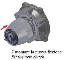
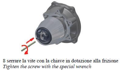
25 25 Finish to remount the cover with reverse support and the clutch shaft starting from table 19 and proceed to the contrary until the table 2 (*). Tighten the screw of the clutch, to the engine (or to the gearbox if old model) at 3 kgm (table 2) Tighten the 6 nuts S of the rear cover at 2,7 kgm (table 7) Tighten the 2 nuts X of the wheels s hubs at 8,5 Kgm (machines without differential) (table 16) Tighten the 6 nuts L of the semi-axles at 2,7 kgm (machines with differential) (table 5) Tighten the 2 screws M10 of the reverse support at 5 kgm (table 18) For the tightenings above, always use adhesive as Loctite strong threadlocker For the adjustment and the correct mounting see also table 27 To fit the clutches on engines with cylindrical shaft see table 28 (*) per il sigillante silicone vedere la favola 26 For the silicone sealant see table 26

26 26 Flange of the reverse speed B example for all gearbox s flanges Inside the holes In the internal side of the holes A C Special tongs to mount the PTO balls For the adjustment and the correct mounting see also tables 27 and 28

27 27 Smontaggio cambio Motocoltivatori e Motofalciatrici measure to be checked at mount about Step measure to be checked at mount 5 mm wear 3 mm separation (measure to be checked at mount)
28 28
Serial Number Range Electric Start & Bumper
 850 Electric Start & Bumper Serial Number Range 1000-6663 01.00 1 300.00276 KEY 2 300.00277 SWITCH 3 311.11090 SCREW M6X10 4 311.12158 SCREW M8X70 VANGARD ENGINE 5 312.11060 NUT M6 6 312.41060 NUT, SELF
LIFT TRUCK SERIES: G35S-2 G40S-2 G45S-2 G40SC-2 G45SC-2 G50SC-2. November 15, 2000 CODE 3150 LT3150-L0 SUBJECT: NEW DRIVE AXLE
 LIFT TRUCK SERIES: G35S-2 G40S-2 G45S-2 G40SC-2 G45SC-2 G50SC-2 November 15, 2000 CODE 3150 LT3150-L0 SUBJECT: NEW DRIVE AXLE A new drive axle has been introduced in the above model lift trucks. The purpose
Illustrated Parts: Model 712 GX8
 Illustrated Parts: Model 712 GX8 BCS America LLC 5001 N Lagoon Ave Portland, OR 97217 Revised 07/11/2017 www.bcsamerica.com Phone: 800-543-1040 Fax: 800-777-7069 Bumper ------ - 823722 01.00 700-01.1-01.02
Illustrated Parts: Model 712 GX5
 Illustrated Parts: Model 712 GX5 BCS America LLC 5001 N Lagoon Ave Portland, OR 97217 Revised 07/11/2017 www.bcsamerica.com Phone: 800-543-1040 Fax: 800-777-7069 Bumper ------ - 823722 01.00 Revised 12/28/2011
SERVICE MANUAL STEERING AND RIGID DRIVE AXLES SERIES 068. Date Revision Description Owner 06/10/ Document emission PM
 SERVICE MANUAL STEERING AND RIGID DRIVE AXLES SERIES 068 Date Revision Description Owner 06/10/09 1.0 Document emission PM COMER INDUSTRIES Axles & Wheel Drive Units Via Magellano, 37-42046 Reggiolo (RE)
SISU DP-330 DRIVE GEAR. Maintenance Manual
 SISU DP-330 DRIVE GEAR Maintenance Manual Sisu Axles, Inc. Autotehtaantie 1 PO Box 189 Fin-13101 Hameenlinna Finland Phone +358 204 55 2999 Fax +358 204 55 2900 DP330DG.PDF (3/2007) TABLE OF CONTENTS
Serial Number Range Electric Start & Bumper
 Electric Start & Bumper 100000-124663 01.00 1 300.00276 KEY 2 300.00277 SWITCH 3 311.11090 SCREW TE M6X10 4 311.12158 SCREW M8X70 5 312.11060 NUT M6 6 312.41060 NUT, SELF LOCKING M6 7 312.41080 NUT, SELF
Model 4360 Teardown and Reassembly Instructions
 Clean the outside surface of the transaxle. Place the shifter in neutral position. Remove detent cover screw (item 3), detent cover (item 4), detent springs (item 5), and detent balls (item 6). Use a magnet
Fisher 1061 Pneumatic Piston Rotary Actuator with Style H & J Mounting Adaptations
 Instruction Manual 1061 H & J Actuator Fisher 1061 Pneumatic Piston Rotary Actuator with Style H & J Mounting Adaptations Contents Introduction... 1 Scope of Manual... 1 Description... 2 Specifications...
Illustrated Parts: Duplex Cutter Bars
 BCS America LLC 5001 N Lagoon Ave Portland, OR 97217 Illustrated Parts: Duplex Cutter Bars 2013 + Transmission Hood, Decals Revised 7/10/2017 www.bcsamerica.com Phone: 800-543-1040 Fax: 800-777-7069 s
SECTION 3A FRONT DRIVE AXLE TABLE OF CONTENTS SPECIFICATIONS GENERAL SPECIFICATIONS. Description Drive Shaft Type. CV Joint Axle Housing Type
 SECTION 3A FRONT DRIVE AXLE TABLE OF CONTENTS Specifications........................ 3A-1 General Specifications.................. 3A-1 Fastener Tightening Specifications......... 3A-2 Component Locator...................
Illustrated Parts: Model 739
 Illustrated Parts: Model Power Safe BCS America LLC 00 N Lagoon Ave Portland, OR Revised -- www.bcsamerica.com Phone: 00--00 Fax: 00--0 Bumper / Accessories - ------- 0.00 0 00 SCREW, X 0 SCREW, HEX MX
Section B Detector September B
 Section B Detector September 200 B Index No. Part No. Description. 2-0030-000 Link 2. 2-0208-000 Deck Hook Selector Assembly 3. 2-003-000 Spacer. -3000-000 Ball Bearing. 2-00-02 X-Washer Pin. 2-008-02
Repair Manual Ford DPS6 Gearbox. INA GearBOX
 Repair Manual Ford DPS6 Gearbox INA GearBOX Special Tools Tool kit (400 0477 10) for professional repair of the Ford DPS6 gearbox. Assembly table: Table (A) for securing the shafts, gear shift positions
DISASSEMBLY AND ASSEMBLY (Continued)
") 205-03-23 Front Drive Axle/Differential Ford 8.8-Inch Ring Gear 205-03-23 49. Measure the ring gear backlash at four places to obtain a consistent reading. 1 Mount the special tools on the indicator base.
205-03-23 Front Drive Axle/Differential Ford 8.8-Inch Ring Gear 205-03-23 49. Measure the ring gear backlash at four places to obtain a consistent reading. 1 Mount the special tools on the indicator base.
STANDARD DANA REAR ELECTRIC AXLE & BRAKES
 37 30 29 31 33 34 36 4 5 6 3 7 9 5 4 8 39 8 4 5 9 21 25 27 23 1 24 21 20 22 30 28 23 26 22 10 12 11 11 13 14 13 1 2 1 15 37 33 31 2 16 34 35 17 36 38 18 19 (10x) 26m 50 62 63 SHOE ID: INKED ID 4070FF 55
HR24TS Rotary Rake. Serial Numbers and higher. Illustrated Parts Breakdown. Guards and Guard Arm, Front Hay Curtain Mount.
 HRTS Rotary Rake Serial Numbers 00 and higher Illustrated Parts Breakdown Page Page Page Page Page Page Page Page Page Page 0 Page Page Page Page Page Page Page Page Page Page 0 Tongue Front Frame Guards
PARTS MANUAL FOR R22N/H REAR AXLE
 PARTS MANUAL FOR REAR AXLE MARMON-HERRINGTON ALL-WHEEL DRIVE 13001 Magisterial Drive Louisville, KY 40223 TABLE OF CONTENTS REPLACEMENT PARTS & WARRANTY CLAIM PROCEDURE......... 3 DIFFERENTIAL CARRIER
615 Service Manual SERVICE MANUAL. 615 Series Axle
 SERVICE MANUAL 615 Series Axle Issue 1 - February 2002 CONTENT: 1 INTRODUCTION... Page - 1-2 GENERAL DESCRIPTION... Page - 1-3 IDENTIFICATION... Page - 1-4 GENERAL SERVICE INFORMATION... 4.1 Routine Maintenance...
ATTENTION ADVANCE SERVICE BULLETIN INFORMATION
 SUBJECT: NO: 21-10-98 Loss Of Fifth Gear GROUP: Transmission EFFECTIVE DATE: Sep. 11, 1998 CHRYSLER MAIL MANAGEMENT SYSTEM DATE: AUG. 28, 1998 ATTENTION ADVANCE SERVICE BULLETIN INFORMATION The following
SERVICE MANUAL. 915 Series Axle
 SERVICE MANUAL 915 Series Axle Issue 1 September 2003 CONTENT: 1 INTRODUCTION Page 3-2 GENERAL DESCRIPTION Page 3-3 IDENTIFICATION Page 3-4 GENERAL SERVICE INFORMATION Page 5 -.1 4.1 Routine Maintenance
250P Manure Spreader
 0P Manure Spreader Illustrated Parts Breakdown Page - Page Page Page Page Page Page Page Page Page Page Page Page Page Page - Page Page Page 0 Complete Front End PTO/Jack/Hitch Assembly Front Pulley Assembly
22 SECTION 18 - CLUTCH - CHAPTER 1
 22 SECTION 8 - CLUTCH - CHAPTER PTO CLUTCH CONTROL SYSTEM ADJUSTMENT 43 See Section 3 PTO for details on PTO clutch servo control adjustment, and for the PTO engage switch adjustment. SECTION 2 - TRANSMISSIONS
Off-Highway Axle Planetary Wheel Ends
 Maintenance Manual MM-1189 Off-Highway Axle Planetary Wheel Ends Revised 06-16 Service Notes About This Manual This manual provides service and repair procedures for planetary wheel ends on off-highway
MTMANUAL TRANSMISSION GENERAL 1. SPECIFICATIONS. 1) General Specifications. 2) Tightening Torque MANUAL TRANSMISSION
 General Specifications. 2) Tightening Torque MANUAL TRANSMISSION") 03-3 MT GENERAL 1. SPECIFICATIONS 1) General Specifications 2) Tightening Torque 03-4 OVERVIEW AND OPERATION PROCESS 1. OVERVIEW 4WD Features 1. All gears use the helical type and high strength materials.
03-3 MT GENERAL 1. SPECIFICATIONS 1) General Specifications 2) Tightening Torque 03-4 OVERVIEW AND OPERATION PROCESS 1. OVERVIEW 4WD Features 1. All gears use the helical type and high strength materials.
26 Hume Reserve Court, Nth. Geelong, 3215 Phone: (03) Fax: (03) INSTALLATION MANUAL. for
 Fax: (03) INSTALLATION MANUAL. for") 26 Hume Reserve Court, Nth. Geelong, 3215 Phone: (03) 5272 2844 Fax: (03) 5272 2633 GEARLESS CENTRE DIFFERENTIAL FULL-TIME 4X4 TRANSFER CASE CONVERSION DEDICATED LOW RANGE INSTALLATION MANUAL for TOYOTA
26 Hume Reserve Court, Nth. Geelong, 3215 Phone: (03) 5272 2844 Fax: (03) 5272 2633 GEARLESS CENTRE DIFFERENTIAL FULL-TIME 4X4 TRANSFER CASE CONVERSION DEDICATED LOW RANGE INSTALLATION MANUAL for TOYOTA
Repair Manual VW 02J gearbox. INA GearBOX
 Repair Manual VW 02J gearbox INA GearBOX Special tools Pipe section, 50 mm: Press fitting of synchronizer body for third/fourth gear. Assembly of support bearing for input and output shaft. Part number:
HR930 Rotary Rake. Illustrated Parts Breakdown. Tongue & Main Frame. Gearbox & Tine Arm
 HR0 Rotary Rake Illustrated Parts Breakdown Page Page Page Page Page Page Tongue & Main Frame Guards Gearbox & Tine Arm Axle Assembly Rotary Gearbox PTO Shaft 0//0 Tongue & Main Frame 0 0 0 0 Ref# Description
Models 642E, 642F, 662E, 644E, 664F, & 6A4E
 Models E, F, E, E, F, & AE 0 0 0 0 Models E, F, E, E, F, & AE. -0 Lock Jam Nut /-. -0 Flat Idler. -B Auger Idler Arm. 0-0A Hex Cap Screw /- x.0. -0 Bushing. -0 Bell Washer. -00 Hex Nut /-. -0 Hex Lock
TT4100 Rotary Tedder
 TT0 Rotary Tedder Serial numbers 0 and higher Illustrated Parts Breakdown Page Page Tongue Assembly S/N - Tongue Assembly S/N to Page Page Page Page Page Tongue Assembly S/N to Tongue Assembly S/N + Main
Maintenance Manual FP-330 Drive Gear
 Maintenance Manual FP-330 Drive Gear Sisu Axles, Inc. Autotehtaantie 1 P.O. Box 189 FIN-13101 Hämeenlinna Finland Phone int + 358 204 55 2999 Fax int + 358 204 55 2900 FP330DG 2/2008 Maintenance Manual
REMOVAL & INSTALLATION
 REMOVAL & INSTALLATION Removal 1. Center steering wheel. Disconnect negative battery cable. Remove steering coupling shield (if equipped). Disconnect steering shaft at flexible coupling or pot joint. Note
MAINTENANCE MANUAL DP-265
 MAINTENANCE MANUAL DP-265 Drive Gears Sisu Axles, Inc. Autotehtaantie 1 P.O. Box 189 FIN-13101 Hämeenlinna Finland Phone int + 358 204 55 2999 Fax int + 358 204 55 2900 DP265DG.PDF (2/2003) k Table of
CHASSIS CONTENTS EXTERIOR PARTS 6-1 FRAME COVER 6-2 REAR FRAME COVER 6-4 FRONT WHEEL 6-6 FRONT BRAKE 6-10 HANDLEBARS 6-17 FRONT FORK 6-19
 CHASSIS CONTENTS EXTERIOR PARTS 6- FRAME COVER 6- REAR FRAME COVER 6-4 FRONT WHEEL 6-6 FRONT BRAKE 6-0 HANDLEBARS 6-7 FRONT FORK 6-9 STEERING 6-6 REAR WHEEL 6-3 REAR BRAKE 6-39 6 REAR SHOCK ABSORBER 6-43
Toyota Truck Park Brake Bellcrank Repair
 Toyota Truck Park Brake Bellcrank Repair Toyota trucks including Tacoma, T100 and Tundra with rear drum brakes use a bellcrank apparatus through the brake backing plate as part of the parking brake system.
6 15. Ease off the adjuster and remove t h e spreader REAR DIFFERENTIAL-ONE TEN. 8. Remove the fixings and withdraw the differential bearing caps.
 ...,.....,... OVERHAUL REAR AXLE DIFFERENTIAL.. ASSEMBLY (SALISBURY) LAND ROVER ONE TEN MODELS 8. Remove the fixings and withdraw the differential bearing caps. Service tools: 47 screw press; 131 C axle
DRIVE AXLES. Differentials & Axle Shafts - Corvette
 DESCRIPTION & OPERATION 1998-99 DRIVE AXLES Differentials & Axle Shafts - Corvette A Getrag 625 model differential is used on both the automatic and manual transmissions. Differential carrier and case
PART NO DESCRIPTION DENOMINACION NOTES
 730 GX11 Bumper 01.00 1 311.12158 SCREW M8X70 TORNILLO M8X60 2 314.11084 FLAT WASHER 8.4 AUANDELA PLANA 8.4 3 312.41080 NUT, SELF LOCKING M8 TUERCA AUTOBLOC. M8 4 590.56053 BUMPER 730 GX11 Serial Number
Service Manual. #19 Gearmatic Winch
 Allis Chalmers Service Manual #19 Gearmatic Winch Service Manual THIS IS A MANUAL PRODUCED BY JENSALES INC. WITHOUT THE AUTHORIZATION OF ALLIS CHALMERS OR IT S SUCCESSORS. ALLIS CHALMERS AND IT S SUCCESSORS
23. Planetary Gear and Low Clutch S510212
 Automatic Transmission 23. Planetary Gear and Low Clutch S510212 A: REMOVAL S510212A18 1) Extract the torque converter clutch assembly. 2) Remove
Technical Note6019A X61, and TL4 - X77, and TL4 - X84, and TL4 - X85, and TL4 - X91, and TL4 - X95, and TL4 TL4 manual gearbox
 Technical Note6019A X61, and TL4 - X77, and TL4 - X84, and TL4 - X85, and TL4 - X91, and TL4 - X95, and TL4 TL4 manual gearbox Edition 9 77 11 335 822 APRIL 2009 Edition Anglaise "The repair methods given
DISASSEMBLY AND ASSEMBLY
 205-03-1 Front Drive Axle/Differential Ford 8.8-Inch Ring Gear 205-03-1 DISASSEMBLY AND ASSEMBLY Axle Front Drive Special Tool(s) 2-Jaw Puller 205-D072 (D97L-4221-A) Special Tool(s) Carrier Bearing Replacer
Supplement to Spare Parts Catalogue. Model : FT Dual Transmission - F
 Supplement to Spare Parts Catalogue Model : FT - 60 Dual Transmission - F10001760 CONTENTS Tab. No. Sheet No. DESCRIPTION Page No. 1 101764-8 HEAD LIGHT, REAR LIGHT AND PLOUGH 1 LAMP 2 101766A-7 SHEET
The chronograph calibres CHRO PC 17 jewels CHRO C12 PC 17 jewels CHRO C12 PC AMPM GMT 17 jewels CHRO PC CAL 17 jewels
 Technical guide The chronograph calibres 860 27 CHRO PC 17 jewels 861 27 CHRO C12 PC 17 jewels 910 27 CHRO C12 PC AMPM GMT 17 jewels 930 27 CHRO PC CAL 17 jewels o 27.00 mm / Power-reserve Jewel number
26 Hume Reserve Court, Nth. Geelong, 3215 Phone: (03) Fax: (03) DUAL RANGE HIGH SPEED INSTALLATION MANUAL. for
 Fax: (03) DUAL RANGE HIGH SPEED INSTALLATION MANUAL. for") 26 Hume Reserve Court, Nth. Geelong, 3215 Phone: (03) 5272 2844 Fax: (03) 5272 2633 GEARLESS CENTRE DIFFERENTIAL FULL-TIME 4X4 TRANSFER CASE CONVERSION DUAL RANGE HIGH SPEED INSTALLATION MANUAL for TOYOTA
26 Hume Reserve Court, Nth. Geelong, 3215 Phone: (03) 5272 2844 Fax: (03) 5272 2633 GEARLESS CENTRE DIFFERENTIAL FULL-TIME 4X4 TRANSFER CASE CONVERSION DUAL RANGE HIGH SPEED INSTALLATION MANUAL for TOYOTA
TT8101 Rotary Tedder
 TT0 Rotary Tedder Illustrated Parts Breakdown Page Front End Page Page Transport Axle Assembly Cylinder Linkage Page Guards Page Page Page Page Transport Lock Assembly Lift Frame Assembly Center Tunnel
REEDSTER 125cc. versions: F1 - F2 - F3 - F4 OVERHAULING MANUAL
 REEDSTER 125cc versions: F1 - F2 - F3 - F4 OVERHAULING MANUAL 07/11/07 21/01/2009 1 INDEX Page 1. - REEDSTER 125cc ENGINE DISASSEMBLY 1 2. - CRANKSHAFT DISASSEMBLY / ASSEMBLY 13 2.1 - CRANKSHAFT DISASSEMBLY
REAR AXLE Click on the applicable bookmark to selected the required model year
 REAR AXLE 27-2 REAR AXLE General Information GENERAL INFORMATION 27100010118 The rear axle is a banjo-type semi-floating type. The axle shaft bearings are: *Single taper bearings for vehicles without
Front mechanical suspensions
 FRONT MECHANICAL SUSPENSIONS 9 PRINT 603.43.351/D Front mechanical suspensions Page DESCRIPTION... 11 ARTICULATED QUADRILATERAL SUSPENSION WITH TRANSVERSE LEAF SPRING... 11 SPECIFICATIONS AND DATA... 12
BPW Trailer axle HZF ECO Plus
 BPW Trailer axle HZF 900-5 ECO Plus L ( form closure ( square ) ) Brake SN 428 for ABS, with sensors Track 840 mm, Spring centre 950 mm, Booster bracket centre 4 mm for diaphragm cylinder, AGS ECO-Master,
1999 F-150/250 Workshop Manual
 Page 1 of 30 SECTION 205-03: Front Drive Axle/Differential Ford 8.8-Inch Ring Gear 1999 F-150/250 Workshop Manual DISASSEMBLY AND ASSEMBLY Procedure revision date: 01/08/2003 Axle Front Drive Special Tool(s)
1989 Jeep Cherokee. STEERING COLUMN' '1989 STEERING Jeep Steering Columns STEERING COLUMN STEERING Jeep Steering Columns
 STEERING COLUMN 1989 STEERING Jeep Steering Columns DESCRIPTION All models use collapsible steering columns. All columns have integral ignition switch and locking device. Optional tilt wheel is available
Service Manual. Axle 213
 Service Manual Axle 213 ASM-0026E June 2012 CONTENTS INTRODUCTION... 5 SPECIFICATIONS...6 DEFINITION OF VIEWPOINTS... 6 DATA PLATE... 6 CONVERSION TABLES... 7 TORQUE SPECIFICATIONS... 8 COARSE PITCH...
DF 78. HINT: Face the rough side of the thrust washer marked by # to the differential case. INSPECTION
 78 DIFFERENTIAL REAR DIFFERENTIAL CARRIER ASSEMBLY (w/ Differential Lock) Face the rough side of the thrust washer marked by # to the differential case. INSPECTION 1. DIFFERENTIAL SIDE GEAR (w/ LSD Differential)
SISU MP-330 DRIVE GEAR. Maintenance Manual
 SISU MP-330 DRIVE GEAR Maintenance Manual Sisu Axles, Inc. Autotehtaantie 1 PO Box 189 Fin-13101 Hameenlinna Finland Phone +358 204 55 2999 Fax +358 204 55 2900 MP330DG.PDF (4/2007) TABLE OF CONTENTS
TC20 Chain Driven Power Take-Off Overhaul Instructions
 TC20 Chain Driven Power Take-Off Overhaul Instructions Table of Contents Section Page Introduction 4 Ordering Repair Parts 4 General Information 5 Special Tools 6 Disassembly See Page 2 Reassembly See
PARTS LIST AND SERVICE MANUAL
 CD40 SERIES PTO PARTS LIST AND SERVICE MANUAL HEAVY DUTY, CONSTANT DRIVE PTO FOR THE ALLISON WORLD TRANSMISSION CD40 SERIES CONSTANT DRIVE PTO EXPLODED VIEW CD40 COVER DETAIL (Backside) PTO ASSEMBLY ARRANGEMENTS
DRIVE AXLE Nissan 240SX DESCRIPTION & OPERATION AXLE RATIO & IDENTIFICATION AXLE SHAFT & BEARING R & I DRIVE SHAFT R & I
 DRIVE AXLE 1990 Nissan 240SX 1990 DRIVE AXLES Rear Axle - R200 240SX, 300ZX DESCRIPTION & OPERATION The axle assembly is a hypoid type gear with integral carrier housing. The pinion bearing preload adjustment
62 Deck Idler Kit High Speed
 Part No. 00 FORM NO. -899 6 Deck Idler Kit High Speed For Model 70 Serial No. 99000 to 99000 For Model 7 Serial No. 9900 to 99000 INSTALLATION INSTRUCTIONS Loose Parts Note: Use the chart below to identify
Valtek Auxiliary Handwheels and Limit Stops
 Valtek Auxiliary s and Limit Stops Table of Contents Page 1 General information 2 Installation 2 Side-mounted handwheels, size 25 and 50 (linear actuators) 3 Side-mounted handwheels, size 100 and 200 (linear
MANUAL TRANSAXLE Return to Main Table of Contents
 MANUAL TRANSAXLE Return to Main Table of Contents GENERAL... 2 MANUAL TRANSAXLE CONTROL... 12 SHIFT LEVER ASSEMBLY... 14 MANUAL TRANSAXLE... 15 MANUAL TRANSAXLE ASSEMBLY... 17 FIFTH SPEED SYNCHRONIZER
KAM 7 S Rotary cultivator. Documents. KAM 7 S Rotary cultivator. Speed-change gear box. Clutch. Clutch (Diesel) Gears (Gearbox) Axle with differential
 Gears (Gearbox) Axle with differential") Documents Speed-change gear box Clutch Clutch (Diesel) Gears (Gearbox) Axle with differential Brakes and wheels Internals controls Handlebar rod and handle bars 60 cm rotor with adjustable cowling and
Documents Speed-change gear box Clutch Clutch (Diesel) Gears (Gearbox) Axle with differential Brakes and wheels Internals controls Handlebar rod and handle bars 60 cm rotor with adjustable cowling and
TT4101 Rotary Tedder
 TT Rotary Tedder 0//0 Illustrated Parts Breakdown Page Page Page Page Page Page Page Page Page Page Page Tongue Assembly S/N S/N - Tongue Assembly S/N + Main Frame S/N - Main Frame S/N to Main Frame S/N
DRIVE AXLE - INTEGRAL HOUSING
 DRIVE AXLE - INTEGRAL HOUSING 1993 Toyota Celica 1993 DRIVE AXLES Toyota Differentials & Axle Shafts - Integral Housing Toyota; Celica All-Trac DESCRIPTION Drive axle assembly is a hypoid type with integral
Transfer Valve Actuator Overhaul Instructions
 Rotary Style Transfer Valve Actuators Overhaul Instructions Form No. F-1031 Section 2315 Issue Date 12/10/99 Rev. Date 11/02/11 Table of Contents Introduction.................................. 1 Safety
Transmission MV702. Product Installation & Troubleshooting
 Transmission MV702 Product Installation & Troubleshooting 39036A 2018 I Remove transmission Product installation MV702 1) Remove mower wheels, plastic covers and axle gears from both sides 2) Remove belt
Section 7 REAR END MAINTENANCE AND REPAIR
 TABLE OF CONTENTS PAGE INTRODUCTION...7-2 MAINTENANCE AND LUBRICANT...7-3 DEFINITION OF VIEW POINTS...7-3 DATA PLATE...7-3 MAINTENANCE POINTS...7-4 MAINTENANCE INTERVALS...7-5 ADJUSTMENT AND CHECKS...7-5
Single reduction Differential Carrier Series 7 - MS15 - MS16 - MS17 - MR15 Revised April 2003
 an ArvinMeritor brand Maintenance manual no. MM-0140 Single reduction Differential Carrier Series 7 - MS15 - MS16 - MS17 - MR15 Revised April 2003 Table of contents pg. 05 Section 1: Introduction 06 Description
REAR TRANSMISSION-REAR AXLE
 REAR TRANSMISSION-REAR AXLE The rear axle is of the semi-floating type with a spiral bevel drive pinion and crown wheel as shown in the section view, Fig. 168. 7 The drive is splined into the front transmission
Aerial Platform with Spec No.: AT-146-3A-00090
 Supplement AT-146TE-3/S1-1E-2 Aerial Platform with Spec No.: AT-146-3A-00090 This document is a supplement to the existing service manual with Publication No.: AT-146TE-3/S1-1E. The specifications of this
1. General Description
 1. General Description A: SPECIFICATION 1. MANUAL TRANSMISSION AND FRONT DIFFERENTIAL Type Transmission gear ratio Front reduction gear Rear reduction gear Front differential Center differential Final
Model Series E6A5E, E645E & E665E
 Model Series EAE, EE & EE 0. -0 Housing R.H. -0 Housing L.H.. 0-0 Hex Screw /- x.. -0A Spiral Axle -00A Spiral Axle. -0 Key. -0 Pin-Spiral. -0 Shaft-Worm. -0 Gear-Worm. -0 Collar-Thrust. -0 Plug 0. -0
CHASSIS CONTENTS EXTERIOR PARTS 7-1 FRONT WHEEL 7-2 FRONT BRAKE 7-6 HANDLEBARS 7-13 FRONT FORK 7-15 STEERING 7-23 REAR WHEEL 7-26 REAR BRAKE 7-30
 CHASSIS CONTENTS EXTERIOR PARTS 7- FRONT WHEEL 7-2 FRONT BRAKE 7-6 HANDLEBARS 7-3 FRONT FORK 7-5 STEERING 7-23 REAR WHEEL 7-26 REAR BRAKE 7-30 REAR SHOCK ABSORBER 7-32 SWING ARM 7-33 7 7- CHASSIS EXTERIOR
DIFFERENTIALS & AXLE SHAFTS
 DIFFERENTIALS & AXLE SHAFTS 2001 Chevrolet Camaro 2000-01 DRIVE AXLES General Motors Differentials & Axle Shafts Chevrolet; Camaro Pontiac; Firebird DESCRIPTION & OPERATION Drive axle is a semi-floating,
Telephone:(925) Fax:(925) Lawrence Drive, Livermore, CA
 Fax:(925) Lawrence Drive, Livermore, CA") Telephone:(95)5-9500 Fax:(95)5-950 5 Lawrence Drive, Livermore, CA 955 www.fabcoautomotive.com Table of Contents This manual covers single and dual rear output versions of the TC- two-speed transfer case
Telephone:(95)5-9500 Fax:(95)5-950 5 Lawrence Drive, Livermore, CA 955 www.fabcoautomotive.com Table of Contents This manual covers single and dual rear output versions of the TC- two-speed transfer case
LuK Repair Solution for manual transmissions. Disassembly and assembly Special tool/failure diagnosis VW 02J
 LuK Repair Solution for manual transmissions Disassembly and assembly Special tool/failure diagnosis VW 02J The content of this brochure shall not be legally binding and is for information purposes only.
Transmission Overhaul Procedures-Bench Service
 How to Assemble the Lower Reverse Idler Gear Assembly Special Instructions In 1996 Eaton changed the reverse idler system design. In the nut design, the reverse idler bearing was lubricated through a hole
Repair Manual VW 02T gearbox. INA GearBOX
 Repair Manual VW 02T gearbox INA GearBOX Special tools Repair Manual for the VW 02T gearbox Drain the transmission fluid (arrow). Remove the gearbox from the vehicle in accordance with the vehicle manufacturer
PARTS MANUAL THIS PAGE INTENTIONALLY LEFT BLANK. Ag-Bag International, Ltd. G7000 June Appendix A
 The parts manual is organized into groups, it is designed to make the locating of parts easier. The exploded drawings also show assembly paths. All parts listed are available from your authorized Ag-Bag
Fisher 657 Diaphragm Actuator Sizes and 87
 Instruction Manual 657 Actuator (30-70 and 87) Fisher 657 Diaphragm Actuator Sizes 30 70 and 87 Contents Introduction... 1 Scope of Manual... 1 Description... 2 Specifications... 2 Installation... 3 Mounting
CHASSIS CONTENTS FRONT WHEEL 6-1 FRONT BRAKE 6-6 FRONT FORK 6-14 STEERING STEM 6-20 REAR WHEEL AND REAR BRAKE 6-25 SUSPENSION 6-31 REAR SWING ARM 6-36
 CHASSIS CONTENTS FRONT WHEEL 6-1 FRONT BRAKE 6-6 FRONT FORK 6-14 STEERING STEM 6-20 REAR WHEEL AND REAR BRAKE 6-25 SUSPENSION 6-31 REAR SWING ARM 6-36 6 6-1 CHASSIS FRONT WHEEL REMOVAL Support the machine
Mandatory X Information Recommended Change. Series/Parts Affected: LS40D, LS40TD, LS50TD and LS60TD Concrete Pumps
 Service Bulletin No. CP20060428 Subject: Remix Shaft Coupler Retrofit Kit Model: LS40D, LS40TD, LS50TD & LS60TD Product Group: Concrete Pump Date: April 28, 2006 SERVICE BULLETIN Group: CP Mandatory X
1 HR-301/D Parts Manual. Table Of Contents
 Table Of Contents 301/D Parts Manual 3 Point Hitch...2 Pull-Type Hitch...4 Main Frame...6 Angle Adjuster - Serial Number 44982 & Prior...8 Rotor Assembly - Serial Number 44982 & Prior...10 Rotor Assembly
CS41 SERIES CLUTCH SHIFT PTO
 CS41 SERIES CLUTCH SHIFT PTO PARTS LIST AND SERVICE MANUAL Patent #2004200334 Muncie Power Products, Inc. CS41 SERIES CLUTCH SHIFT PTO EXPLODED VIEW 46 2 MUNCIE POWER PRODUCTS, INC. PARTS LIST AND DESCRIPTION
2-SPEED TRANSMISSION CON- VERSION FOR THE MAXIMUM BX, MT, ST
 2-SPEED TRANSMISSION CON- VERSION FOR THE MAXIMUM BX, MT, ST 2) Remove the engine by unscrewing the four 4 x 12mm engine mounting screws. Disconnect the throttle rod from the carburetor by rotating the
BRAKE E
 8-1 GENERAL...8-2 SPECIFICATIONS...8-6 COMPONENTS...8-7 FRONT BRAKE...8-12 DISASSEMBLY INSPECTION REASSEMBLY (Pn1, Cu2 3 TON SERIES)...8-12 DISASSEMBLY INSPECTION REASSEMBLY (Pn2 3 TON SERIES)...8-17 BRAKE
HKS 700E. Service Manual June Ver. 2.04
 HKS 700E Service Manual 009 June Ver..04 HKS CO.,LTD 78 KITAYAMA FUJINOMIYA SHIZUOKA JAPAN 48-09 TEL +8(0)544-54-78 FAX +8(0)544-54-40 hks_aviation@hks-power.co.jp http://www.hks-power.co.jp/hks_aviation/
Spearhead Multicut 460 MULTICUT th Edition - July 2015 Part No
 MULTICUT 460 14 th Edition - July 2015 Part No. 8999023 1 Spearhead Multicut 460 Parts Book 14 th Edition July 2015 Spearhead Machinery Ltd Green View Salford Priors Evesham Worcestershire WR11 8SW Tel:
Hudson-Essex. Service Manual Supplement. Hudson Cars 750,001 up
 1 9 2 6 Hudson-Essex Service Manual 1927 Supplement Hudson Cars 750,001 up Hudson Rear Axle (Cars numbered 750,001 and upward) Brakes (Cars numbered 750,001 and upward) See page 18 Transmission Group
LIMITED SLIP DIFFERENTIAL INSTALLATION
 Installation of the limited slip gear can be done with axle out of car or with car lifted to gain access from underneath. Refer to repair manual for proper lifting instructions if car is to be lifted.
HORSE III 8HP ROTO TILLER (S/N ) Page 1 of 25 Bolo Tine Assemblies
 Page 1 of 25 Bolo Tine Assemblies") HORSE III 8HP ROTO TILLER (S/N 640000-855638) Page 1 of 25 Bolo Tine Assemblies HORSE III 8HP ROTO TILLER (S/N 640000-855638) Page 2 of 25 Bolo Tine Assemblies 1 GW-2415 2 S/F TINE HOLDER- welded steel.
HORSE III 8HP ROTO TILLER (S/N 640000-855638) Page 1 of 25 Bolo Tine Assemblies HORSE III 8HP ROTO TILLER (S/N 640000-855638) Page 2 of 25 Bolo Tine Assemblies 1 GW-2415 2 S/F TINE HOLDER- welded steel.
TROUBLESHOOTING SPECIAL TOOL ASSEMBLY AND ADJUSTMENT
 1 INDEX Models FD, FE, FF and SG REAR AXLE 10-1 10-108E-07 CHAPTER 10 REAR AXLE Models FD, FE, FF and SG TROUBLESHOOTING...10-2 10 SPECIAL TOOL...10-3 WHEEL HUB AND RELATED PARTS DISASSEMBLY...10-7 INSPECTION...10-9
TT6101 Rotary Tedder
 TT0 Rotary Tedder 0/0/0 Illustrated Parts Breakdown Page Chassis Assembly Page Page Transport Axle Assembly S/N - Transport Axle Assembly S/N + Page Page Page Page Page Transport Lock Assembly Lift Frame
Short-throw Shifter Installation Guide
 Short-throw Shifter Installation Guide Removal Procedure 1) Remove the shift control knob. A. Lift up on the rear portion of the shift control closeout boot retaining ring and detach the retaining ring
COMPACT WHEEL LOADERS before PIN BH - before PIN Parts Catalog Ingersoll HOME TRACTORS ATTACHMENTS INDEX ENGINES
 R Ingersoll HOME COMPACT WHEEL LOADERS 6018 - before PIN 14190349 6018BH - before PIN 14190351 Parts Catalog 8-3052 TRACTORS ATTACHMENTS INDEX PAINT ENGINES GENERAL INFO PRODUCT IDENTIFICATION NUMBERS
REAR AXLE Click on the applicable bookmark to selected the required model year
 REAR AXLE 27-1 REAR AXLE CONTENTS GENERAL INFORMATION.................. 2 SERVICE SPECIFICATIONS................. 3 LUBRICANTS.............................. 3 SEALANTS AND ADHESIVES.............. 4 SPECIAL
DRIVE AXLE Volvo 960 DESCRIPTION & OPERATION AXLE IDENTIFICATION DRIVE AXLES Volvo Differentials & Axle Shafts
 DRIVE AXLE 1994 Volvo 960 1994 DRIVE AXLES Volvo Differentials & Axle Shafts 960 DESCRIPTION & OPERATION All 960 station wagon models use type 1041 rear axle assembly. All 960 4-door models use type 1045
1994 Mitsubishi Eclipse GS
 APPLICATIONS CHRYSLER MOTORS MANUAL TRANS OVERHAUL - MITSUBISHI W5M & W6M SERIES MANUAL TRANSMISSIONS Mitsubishi W5M31, TRANSMISSION APPLICATIONS (CHRYSLER MOTORS) Vehicle Application Transmission Model
 AUTOGARD SERIES 820 TORQUE LIMITER Installation and Maintenance Manual DB0009 Issue 11 21 Feb 2017 British Autogard Ltd 2 Wilkinson Rd., Love Lane Industrial Estate, Cirencester, Glos., GL7 1YT UK Tel.
B190 8 H.P. Lawn Vacuum (1995) Page 1 of 22 Chute Assembly
 Page 1 of 22 Chute Assembly") 245-315B190 8 H.P. Lawn Vacuum (1995) Page 1 of 22 Chute Assembly 245-315B190 8 H.P. Lawn Vacuum (1995) Page 2 of 22 Chute Assembly Ref # Part Number Qty S/P/F Description 1 681-0068 1 S CHUTE ASSEMBLY
245-315B190 8 H.P. Lawn Vacuum (1995) Page 1 of 22 Chute Assembly 245-315B190 8 H.P. Lawn Vacuum (1995) Page 2 of 22 Chute Assembly Ref # Part Number Qty S/P/F Description 1 681-0068 1 S CHUTE ASSEMBLY